Article

An Analysis of the Kinematical Characteristics of an Eccentric Curve-Face Gear Pair with Compound Motion

1
School of Mechanical and Power Engineering, Chongqing University of Science and Technology, Chongqing 401331, China
2
State Key Laboratory of Mechanical Transmission for Advanced Equipment, Chongqing University, Chongqing 400044, China
*
Author to whom correspondence should be addressed.
Machines 2024, 12(3), 162; https://doi.org/10.3390/machines12030162
Submission received: 18 January 2024 / Revised: 15 February 2024 / Accepted: 19 February 2024 / Published: 27 February 2024
(This article belongs to the Section Machine Design and Theory)

Abstract

:
An atypical face gear pair with complex transmission motion can be used in intermittent reciprocating mechanisms with more precise transmission and a much higher capacity than conventional mechanisms, such as cams and linkages. In this study, we derive a mathematical equation for the complex tooth surface of this gear pair. We indicate the change in root cutting, top sharpening and the effective width of the tooth surface with different parameters. Additionally, we derive the governing equation for the kinematical characteristics of this eccentric curve-face gear pair with a rigid–flexible coupling system, revealing the continuous intermittent contact principle of this gear type with different parameters. Boundary conditions for the gear pair are proposed, demonstrating that the vibration of the gear pair is more obvious, even at a low velocity. In addition, the critical velocity, which mostly ranges from 300 rpm to 400 rpm, is affected by the stiffness of the frames and the parameters of the tooth surfaces. The interval space and interval time of the intermittent contact system are Δ d 0.3   m m and Δ t 5.6 × 10 4   s , with visible surface sliding on the contact area. It is shown that the contact points are firstly concentrated at the outer part of the tooth surface and that the meshing will break off at the first tooth with the minimum inner radius R G i min . These theoretical results, which have been verified experimentally, provide theoretical support for further analysis and the better application of this unconventional gear pair.

1. Introduction

As a compound-motion gear pair, an eccentric curve-face gear pair has the advantages of both gear pair and cam mechanisms with high capability. To some extent, it can be used as a replacement for cam, rod and variable gear mechanisms in, for example, impact drilling, variable pumps, continuous variable transmission and so on. In order to achieve reciprocating motion and rotation simultaneously, the two output shafts of the gear pair must be combined via two parts: a flexible axis for movement and a rigid axis for rotation. Thus, a spring is necessary to hold the axial force, limit the response displacement and reset the position of the moving gear quickly, which is quite different from a normal gear system.
The stiffness of the spring is much lower than the other frame of the gear system. Thus, many research works have only focused on the natural frequency and forced vibration of the spring. Nirala and Michalczyk focused on the natural frequencies of a compression spring using the FEM method, showing that the natural frequency of a helical compression spring will reduce in the transverse mode but increase in both the compression and torsional modes [1,2]. Gu and Yang investigated helical springs subjected to axial loads under different dynamic conditions and described the relationships between the design parameters and the overall mechanical performances of helical springs [3,4]. Hamza and Renno established the mathematical formulas of springs, which are angular and axial deformations and velocities, with a much smaller and faster FE method [5,6]. Further research on springs with a rigid part has been performed by Zhou, Pawar and Gu and others. In detail, Zhou presented an enhanced flexible dynamic model for a cam profile with a spring, like a valve train with clearance and multi-directional deformations, and verified it by experiment [7]. Pawar and Gu developed a transient non-linear model for the natural frequencies and dynamic responses of a spring, with consideration of the material, internal vibration and coil collision [8,9]. Baran presented the analysis of cylindrical springs with different geometric parameters, making it possible to estimate the suitability of a given spring [10]. These studies indicate that the combined application of a spring and rigid cam is feasible, indicating that the response of the spring is affected by the geometric parameters, operating velocity and so on.
An eccentric curve-face gear pair is developed from a conventional gear pair, but the transmission pattern and kinematic characteristics of it are very different from those of conventional pairs because the coupling system is combined with the flexible spring and rigid frame. In the current context, this compound-motion gear pair has only been proposed for a few years, with few scholars focused on it, such as Chao Lin, Dawei Liu and so on. These results indicate that the transmission method for this gear pair can be similar to the method for a conventional gear pair [11,12,13,14]. According to the complicated and heavy geometrical models required during the establishing process of the tooth surface, Maksat developed a novel mathematical model with non-linear equations that were reduced more than those used for the conventional method, making the tooth contact analysis much easier [15,16]. Shaabidov and Xiao investigated the dynamic performance and reliability of a gearbox with time-varying velocity, and variations in the material, strength and size of the abrasive particles, obtaining the mapping rules of the gear pair [17,18]. Jasem and Xie focused on the gear mesh stiffness to validate their proposed gear dynamic model, indicating that the wave face kinematic reducer does not require fulfillment of the conditions for the equality of the center distances [19,20]. Wang and Lo conducted static and dynamic analyses of a spur gear pair with linear tip relief and longitudinal crowning, revealing that the gear dynamic model is effective and advanced for general gear systems, a narrow-faced gear, a wide-faced gear and a gear with tooth profile errors [21,22]. He and Zhou established the time-varying mesh stiffness affected by gear eccentricity and non-involute parameters, showing the dynamic difference between conventional and unconventional gear pairs [23,24]. Yu and He established a gear dynamic model to investigate the system–structure coupling dynamic analysis by combining the mesh stiffness and the time-varying pressure angle, explaining the comprehensive and strong influence of dynamic characteristics caused by the parameters of the tooth surface and structure [25,26].
According to the previous research, we found that the transmission characteristics of an eccentric curve-face gear pair will be influenced by the flexible spring, rotating velocity and parameters of the gear structure. In addition, Spitas found that the dynamic contact situation of the gear pair will result in intermittent contact with multiple DOF and variable torque, and they proposed a simulation method for the tooth contact loss and contact reversal with different parameters [27]. Marjanovic investigated the friction coefficient between the sliding velocity and contact force, indicating that the coefficient has a variable value [28]. These results suggest a reference basis for an eccentric curve-face gear with a variable radius and multiple motions.
In this study, we derive a mathematical equation for the unconventional tooth surface of an eccentric curve-face gear pair. Additionally, a mathematical model for contact points on the engaged tooth surface is constructed, indicating that the transmission process of this gear pair involves continuously intermittent collision rather than rolling. Further, the governing equation for the response of this rigid–flexible coupling system is presented. The further discussion about this kinematic response model with different parameters shows that the critical velocity of the gear pair is much lower, and the kinematic displacement is more obvious, than those of the normal face gear pair. These results, which are verified by experiment, provide theoretical support for the further analysis and practical application of this compound-motion gear pair.

2. Transmission Model of Eccentric Curve-Face Gear Pair

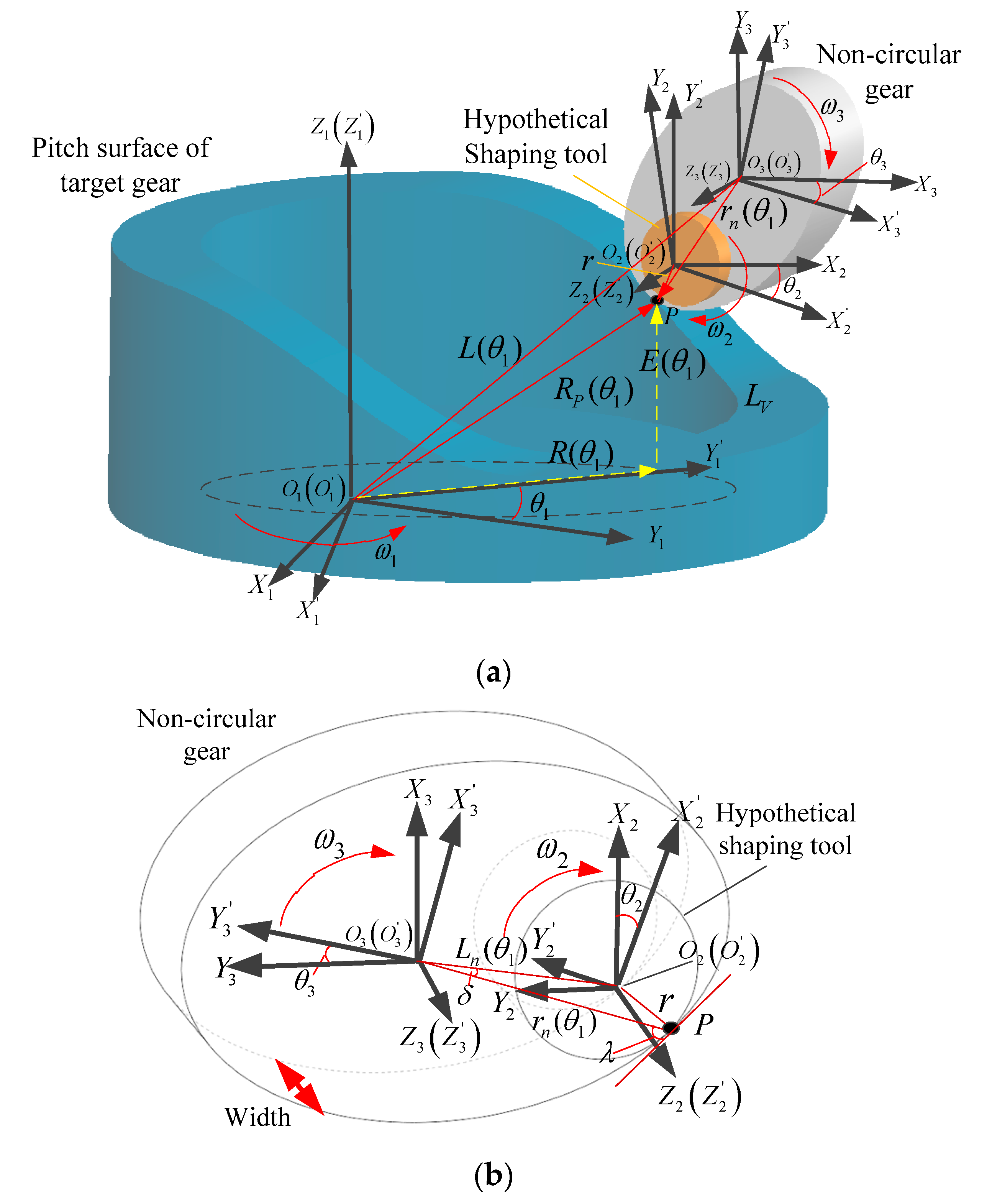
2.1. Equation of Engagement Tooth Surface with Complex Motion

Similarly to a conventional gear pair with a fixed rotating axis, the engaged tooth surface of an eccentric curve-face gear pair can be established using the novel mathematical method and localized contact method [15,29]. Figure 1 shows the fabricating process of an eccentric curve-face gear pair with the same hypothetical shaping tool.
As demonstrated in Figure 1, O 1 -X 1 Y 1 Z 1 and O 1 -X 1 Y 1 Z 1 are the coordinates of an eccentric curve-face gear with fixed axis Z 1 and movable axis Z 1 . O 2 -X 2 Y 2 Z 2 and O 2 -X 2 Y 2 Z 2 are the coordinates of the shaping tool with axis Z 2 fixed and axis Z 2 movable. Fixed O 3 -X 3 Y 3 Z 3 and movable O 3 -X 3 Y 3 Z 3 are the coordinates of the non-circular gear. θ 1 and R ( θ 1 ) are the rotating angle and variable radius of the target eccentric curve-face gear, r n ( θ 1 ) is the variable radius of the non-circular gear at θ 1 , E ( θ 1 ) is the undulating height of the pitch surface on the curve-face gear, θ 2 and θ 3 are the responding angles of the shaping tool and the non-circular gear to θ 1 , L n ( θ 1 ) is the distance between O 2 and O 3 , and L ( θ 1 ) is the distance between O 1 and O 3 with a constant vertical part L V . Both the undulating times n and eccentricity times N are set as 1 in Figure 1.
According to Figure 1a, the time-varying L ( θ 1 ) with L ( θ 1 ) = R ( θ 1 ) + L V can also be written as L ( θ 1 ) = E ( θ 1 ) + R ( θ 1 ) + r n ( θ 1 ) . During the generating process, the shaping tool undergoes purl rolling with both the eccentric curve-face gear and the non-circular gear at the same point P . Therefore, the time-varying transformation matrices from movable O 2 -X 2 Y 2 Z 2 to movable O 3 -X 3 Y 3 Z 3 are proposed as follows:
M O 2 O 2 = cos θ 2 sin θ 2 0 0 sin θ 2 cos θ 2 0 0 0 0 1 0 0 0 0 1   and   M O 3 O 2 = 1 0 0 L n ( θ 1 ) cos ( θ 3 δ ) 0 1 0 L n ( θ 1 ) sin ( θ 3 δ ) 0 0 1 0 0 0 0 1 M O 3 O 3 = cos θ 3 sin θ 3 0 0 sin θ 3 cos θ 3 0 0 0 0 1 0 0 0 0 1
where L n ( θ 1 ) = L n ( θ 1 ) 2 + r 2 - 2 L n ( θ 1 ) r sin δ , δ = arccos L n ( θ 1 ) 2 + r n ( θ 1 ) 2 r 2 2 L n ( θ 1 ) r n ( θ 1 ) , θ 2 = π / 2 + δ θ 3 λ and μ = a r c tan r n ( θ 1 ) / r n ( θ 1 ) .
Similarly, the transformation matrix M O 1 O 3 from movable O 1 -X 1 Y 1 Z 1 to movable O 3 -X 3 Y 3 Z 3 can be analytically presented as
M O 1 O 3 = sin ( θ 3 ) sin ( θ 1 ) cos ( θ 3 ) sin ( θ 1 ) cos ( θ 1 ) R ( θ 1 ) cos ( θ 1 ) sin ( θ 3 ) cos ( θ 1 ) cos ( θ 3 ) cos ( θ 1 ) sin ( θ 1 ) R ( θ 1 ) sin ( θ 1 ) cos ( θ 3 ) sin ( θ 3 ) 0 E ( θ 1 ) 0 0 0 1
Therefore, the tooth surface of the generated curve-face gear can be deduced as
R P ( θ 1 ) = M O 1 O 3 × M O 3 O 3 × M O 3 O 2 × M O 2 O 2 × r P ( θ 1 ) = sin δ sin θ 1 r n ( θ 1 ) 2 + r 2 2 r r n ( θ 1 ) sin λ cos θ 1 r bs + L n ( θ 1 ) R ( θ 1 ) cos ( λ + θ 3 θ os θ s δ ) i 13 cos ( λ + θ 3 θ o 2 θ s ) r bs sin θ 2 sin ( λ + θ 3 θ os θ s δ ) + θ 2 cos ( λ + θ 3 θ os θ s ) sin δ cos θ 1 r n ( θ 1 ) 2 + r 2 2 r r n ( θ 1 ) sin λ + sin θ 1 r bs + L n ( θ 1 ) R ( θ 1 ) cos ( λ + θ 3 θ os θ s δ ) i 13 cos ( λ + θ 3 θ os θ s ) r bs cos θ 2 sin ( λ + θ 3 θ os θ s δ ) + θ 2 cos ( λ + θ 3 θ os θ s ) E ( θ 1 ) cos δ r n ( θ 1 ) 2 + r 2 2 r r n ( θ 1 ) sin λ r bs sin ( λ + θ 3 θ os θ s δ ) + θ s cos ( λ + θ 3 θ os θ s δ )                                                                                                           1
where r bs , θ s and θ os are the radius, expansion angle and starting angle of the tooth profile of the cylindrical shaper tool; i 13 is the transmission ratio of the eccentric curve-face gear and the non-circular gear with i 13 = r n ( θ 1 ) / R P ( θ 1 ) at point P.
The mathematical equation for the tooth surface of the paired non-circular gear can be proposed using the same method as in Equation (1):
r n ( θ 1 ) = M O 3 O 3 × M O 3 O 2 × M O 2 O 2 × r P ( θ 1 ) = r bs cos ( θ os + θ s + θ 3 θ 2 ) ( θ os + θ s ) sin ( θ os + θ s + θ 3 θ 2 ) + L n ( θ 1 ) cos ( θ 2 δ ) r bs cos ( θ os + θ s + θ 3 θ 2 ) + ( θ os + θ s ) sin ( θ os + θ s + θ 3 θ 2 ) + L n ( θ 1 ) cos ( θ 2 δ ) u s 1
where u s is the width of the non-circular gear.

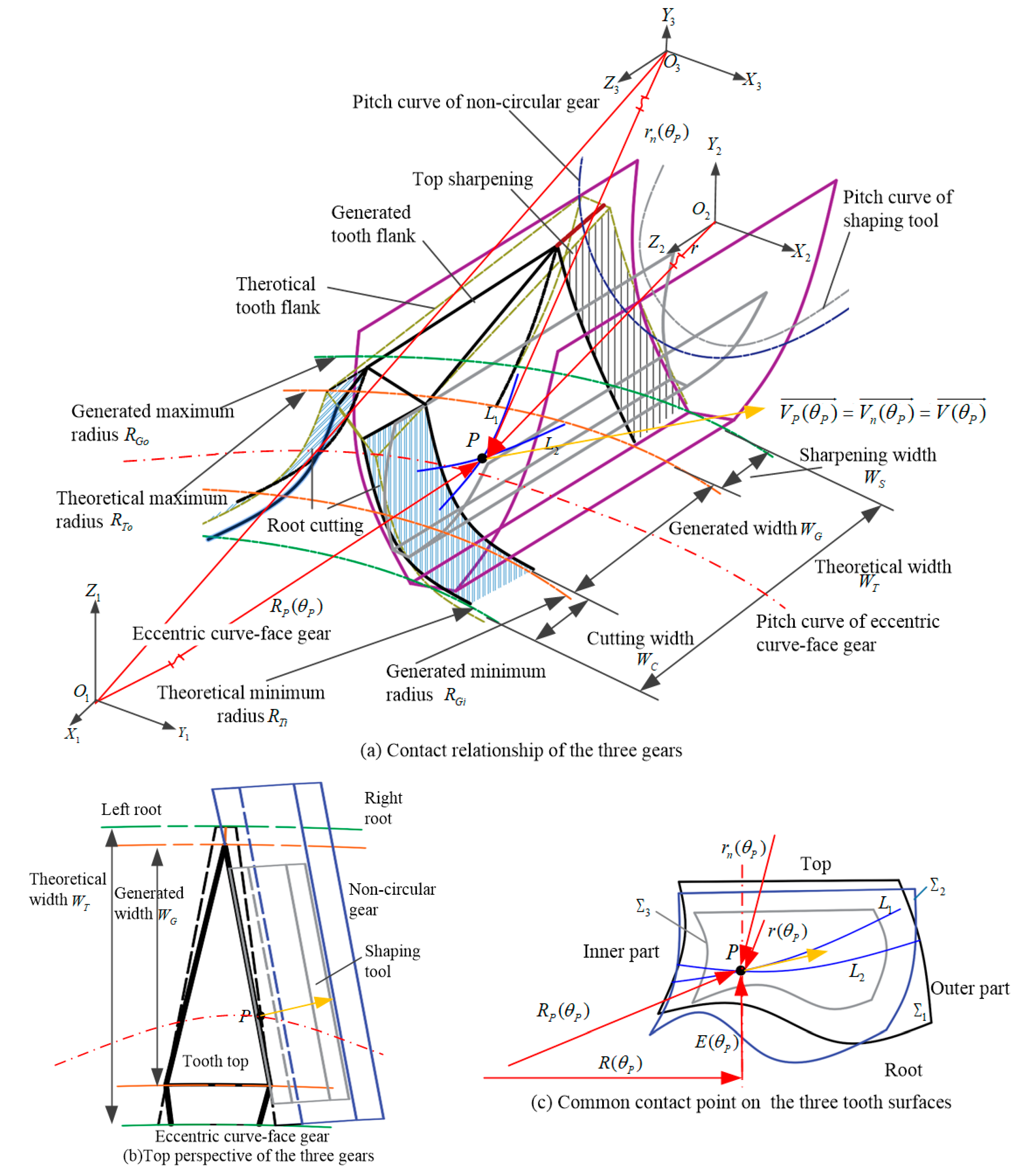
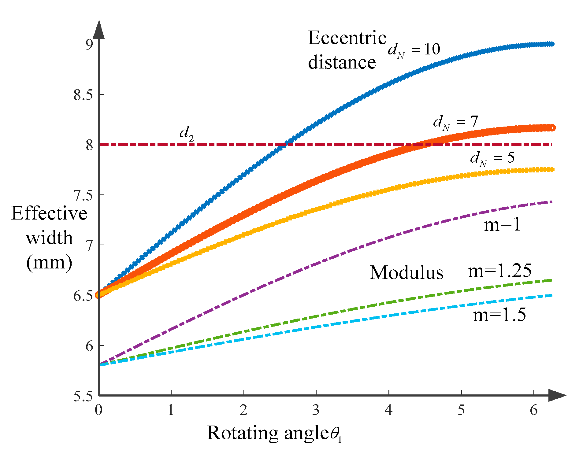
2.2. Effective Surface with Eccentric Pitch Curve

Taking the limitations of root cutting and top sharpening into account, the surface of the eccentric curve-face gear cannot be designed without restriction. The positions and normal vectors on the tooth surfaces of the three gears are always equal at the same meshing point P , which can be demonstrated as R P ( θ P ) = r n ( θ P ) = r ( θ P ) and V P ( θ P ) = V n ( θ P ) = V ( θ P ) in Figure 2.
As shown in Figure 2, Σ 1 , Σ 2 and Σ 3 are the tooth surfaces of the eccentric curve-face gear, non-circular gear and shaping tool, respectively. L 1 and L 2 are the contact lines of the shaping tool with the eccentric curve-face gear and non-circular gear.
The shaping tool, which is shown in Figure 1, is a cylindrical gear required for a good contact situation. Therefore, the radius r ( θ P ) and vector V ( θ P ) on the movable O 2 -X 2 Y 2 Z 2 of the shaping tool are constant:
r ( θ P ) = r b s cos ( θ o s + θ s ) + θ s sin ( θ o s + θ s ) r b s sin ( θ o s + θ s ) θ s cos ( θ o s + θ s )                                                 u s                                                 1
V ( θ P ) = cos ( θ o s + θ s ) sin ( θ o s + θ s ) 0
Substituting Equations (1)–(4) into the relationship equations R P ( θ P ) = r n ( θ P ) = r ( θ P ) and V P ( θ P ) = V n ( θ P ) = V ( θ P ) , the root cutting and top sharpening results can be obtained. The theoretical tooth surface can be divided into three parts: the inner part with root cutting, the outer part with top sharpening and the effective generated part. In addition, the appearance of the root cutting and top sharpening will decrease the thickness of the tooth and increase the variation in the surface curvature. Therefore, it is necessary to analyze the variable effective tooth width for further application of this gear pair. Table 1 shows the values of different parameters of the eccentric curve-face gear pair. Substituting these different values into the relationship Equations (1)–(4), the variable effective tooth width can be shown as per Figure 3, Figure 4 and Figure 5.
When the pitch radius increases from 70 mm to 72 mm, the generated effective tooth width W G increases first with decreased root cutting and then decreases with increasing top sharpening. Specifically, there is a constant value that is obtained between the minimum-top-sharpening and no-root-cutting scenarios with the theoretical pitch curve set as R T i + R T 0 R T i W C W S 2 R θ R T o R T 0 R T i W C W S 2 .
Figure 4 illustrates the cutting height of the eccentric curve-face gear with different eccentricity times N = 1 , 2 , 3 . This indicates that the eccentricity times N only affect the variable times of the cutting height but not the values. Figure 5 shows that the effective width varies with different eccentricity distance d N , modulus m and width d 2 of the non-circular gear. In detail, the eccentricity distance d N has a positive effect on the width and a negative effect on the modulus. When the width is d 2 d 1 , it has no influence on d 1 , the undulating times n or the range of height E ( θ 1 ) . Therefore, the design width of the effective tooth surface should be set as a constant value with W T max < W G min for further manufacturing and application.

3. Kinematic Characteristics of Rigid–Flexible Coupling Gear System

In order to achieve rotation and translation simultaneously, the axis of the eccentric curve-face gear is fixed with the axis of the paired non-circular movable gear. The engagement of this gear pair is complex and prone to sliding, making the contact point offset. The spring is necessary to counteract the radial sliding force and ensure that the non-circular gear resets quickly.

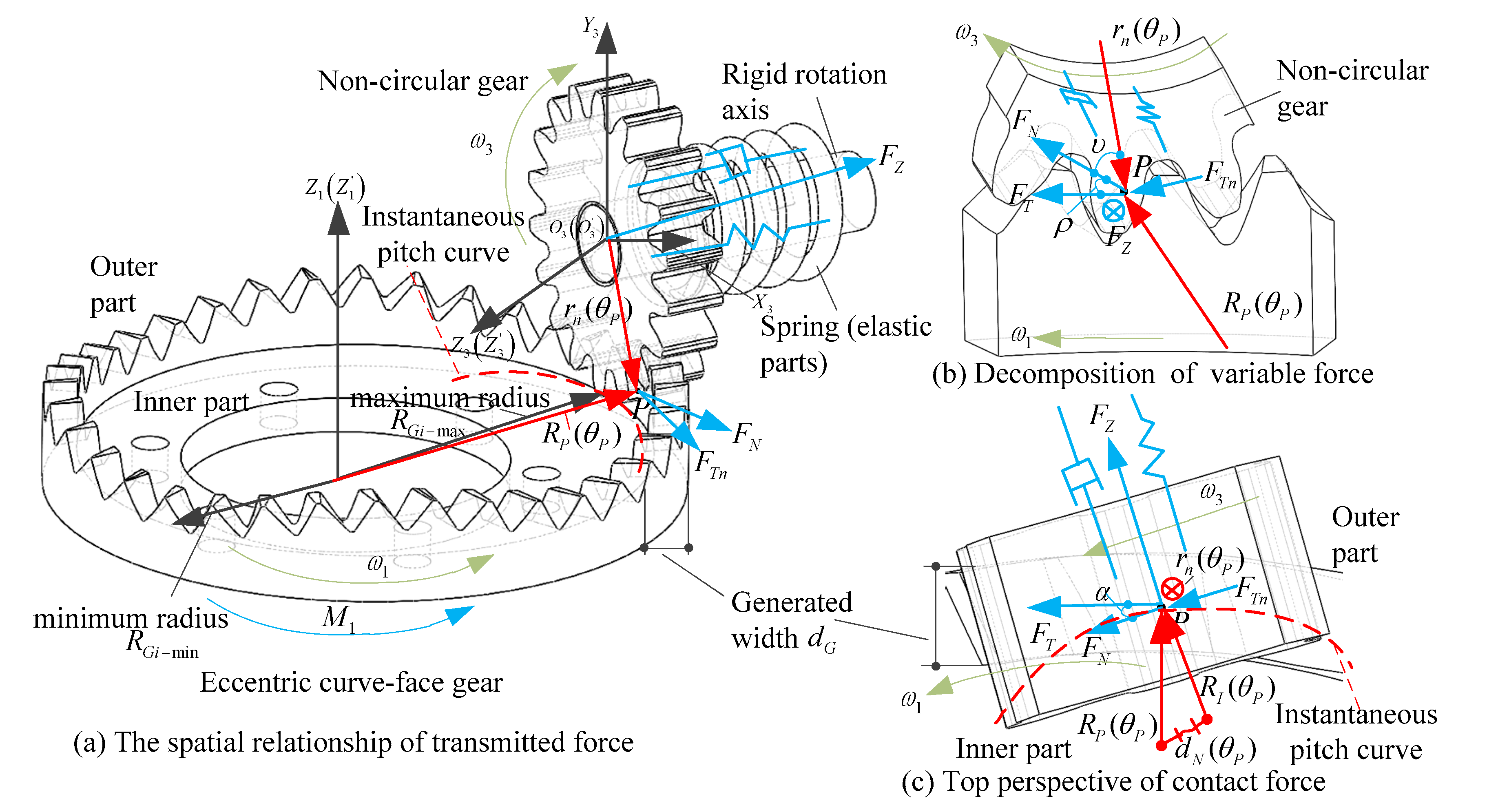
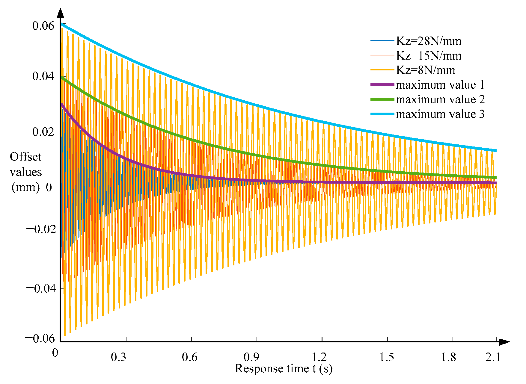
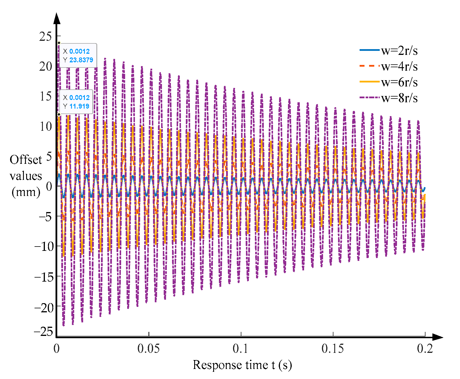
3.1. Response Equation of Rigid–Flexible Coupling System

The spring on the non-circular gear shows much less stiffness than the frame of a conventional gear pair, so it will cause a more obvious kinematic response; it cannot hold the relative displacement of the engaged tooth surface with too large a radial force. During the meshing process of this eccentric curve-face gear pair, the axis of the non-circular gear is usually fixed in the Z 1 direction, described as r P θ P + E ( θ P ) = L V (if necessary, it can also be movable both in the Z 1 and Z 3 directions simultaneously). Therefore, the kinematic response of this rigid–flexible coupling system is mainly manifested as the displacement characteristics of a non-circular gear in the Z 3 direction, as shown in Figure 6.
As illustrated in Figure 6, M 1 is the constant driving torque, F T and F N are tangential and normal contact forces at the point P α , and ρ represents the offset angles between F T and F N in the horizontal and vertical planes. υ  is the offset angle between F T n and F N , which can be obtained using the parameters in Figure 1b. F T n is the response tangential force on the non-circular gear.
The eccentricity times and order of the non-circular gear in Figure 6 are set as N = 1 and n 3 = 2 . The response characteristics of this rigid–flexible coupling system are mainly reflected in the response displacement D Z ( t ) of the non-circular gear and force F Z ( t ) of the spring. M , C Z and K Z are the rigid mass, damping coefficient and stiffness of this coupling system. During the meshing process of the gear pair, the relationship of these forces can be expressed as
F T ( t ) R P ( θ P ) = M 1 θ P = ω 1 t α = arccos R I ( θ P ) 2 R P ( θ P ) 2 d N ( θ P ) 2 2 R P ( θ P ) R I ( θ P ) F Z ( t ) = F T ( t ) sin α F N ( t ) = F T ( t ) cos α cos ρ F T n ( t ) = F N ( t ) sin υ
Therefore, the response forces on the non-circular gear are variable in both the tangential and axial directions. The axial component force F Z ( t ) causes the displacement of the non-circular gear, and the tangential force F T n ( t ) causes the time-varying rotational acceleration of the non-circular gear. In addition, the axial force F Z ( t ) is carried by the spring, so the movement of the coupling system must involve intermittent responses due to the intermittent hysteresis characteristics and lower frequency of the spring compared to other rigid frames. The governing equation for the free vibration S Z ( t ) of the non-circular gear in this coupling system is given with the deformation of the rigid parts ignored.
M S Z ( t ) ·   · + C Z S Z ( t ) · + K Z S Z ( t ) K Z R Z ( 0 ) C Z R Z ( 0 ) · = 0 F Z ( 0 ) = L S R Z ( 0 ) K Z S Z ( 0 ) = D Z ( t k ) D Z ( t k 1 ) S Z ( t ) · = S Z ( t ) d t S Z ( t ) ·   · = 2 S Z ( t ) d t 2
where R Z ( 0 ) is the initial length of the spring at the k t h surface collision. L S is the initial length of the spring.
The parameters of this eccentric curve-face gear pair are periodic, so F Z ( t ) and D Z ( t ) are periodic; this cannot be described directly. Based on the Fourier series, S Z ( t ) can be presented as
S Z ( t ) = a 0 2 + j = 0 ( a j cos ( n j ω t ) + b j sin ( n j ω t ) )
where a j , b j are the j t h coefficients and are shown as a j = 2 0 T D Z ( t ) cos ( n j ω j t ) d t / T , b j = 2 0 T D Z ( t ) sin ( n j ω j t ) d t / T , a 0 = 2 0 T D Z ( t ) d t / T .
Additionally, the solution for the j t h sub-equation of Equation (7) can be given as
S a j ( t ) = a j / K y 1 ω n j ω n 2 2 + ( 2 τ ω n j ω n ) 2 cos ( ω t n j ϕ j ) S b j ( t ) = b j / K y 1 ω n j ω n 2 2 + ( 2 τ ω n j ω n ) 2 sin ( ω t n j ϕ j ) ϕ j = tan 1 2 τ ω n j ω n ( 1 ω n j ω n 2 )
where τ is the damping coefficient with τ = C Z / 2 K Z M , ω n is the natural frequency with ω n = K Z M , and ϕ j is the phase angle of the j t h sub-equation.
Therefore, the total response equation S Z ( t ) of this coupling system is
S Z ( t ) = a 0 2 K Z + n = 1 ( a j / K Z 1 ω n j ω n 2 2 + ( 2 τ ω n j ω n ) 2 cos ( ω t n j ϕ j ) + b j / K Z 1 ω n j ω n 2 2 + ( 2 ω τ n j ω n ) 2 sin ( ω t n j ϕ j ) )
Substituting Equation (9) into Equation (6), the free vibration responses of this coupling system between any two adjacent collisions ( k 1 ) t h and the k t h collision can be obtained. The free response values of this rigid–flexible coupling system with different parameters, i.e., velocity ω , stiffness K Z , initial force F Z ( 0 ) and displacement D Z ( 0 ) , are proposed as shown in Figure 7, Figure 8, Figure 9 and Figure 10.
Figure 7 shows the free vibration of this rigid–flexible coupling system with single contact. Visibly, the change in response values is not completely proportional to the stiffness; with tiny increases in stiffness, the response displacement and required time will decrease more significantly. However, the stronger the spring, the more difficult the installation. The stiffness K Z of the spring should be set to an appropriate value for good installability and transmission performance. Figure 8 shows that the rotational velocity ω only affects the response value, which is also positive in respect of the vibration value. The maximum width d G of the eccentric curve-face gear in this paper is 20 mm, and the two marked initial response displacements are 11.9 mm with ω = 6   r / s and 23.8 mm with ω = 8   r / s . This shows that the response with ω = 8   r / s is greater than the maximum tooth width and the increase in the generated width is beneficial for a higher critical velocity, so the operating velocity of this gear pair should be limited.
Figure 7, Figure 8 and Figure 9 show the vibration values caused by a single k t h collision. It is impossible for this to occur during the gear meshing process because of the numbers of intensive collisions, but the free vibration of any single collision will be covered by the further collisions, as illustrated in Figure 10. With meshing, the single value will be included in the superposition values that result from numerous collisions, exhibiting a consistent fluctuation rather than significant periodic changes with the eccentricity distance.

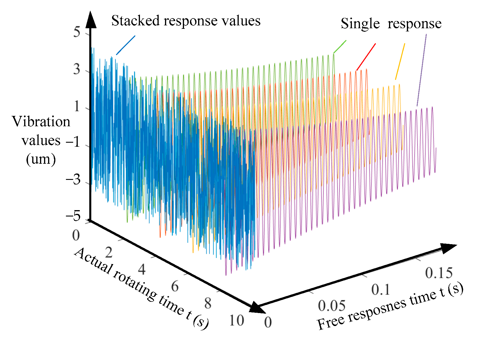
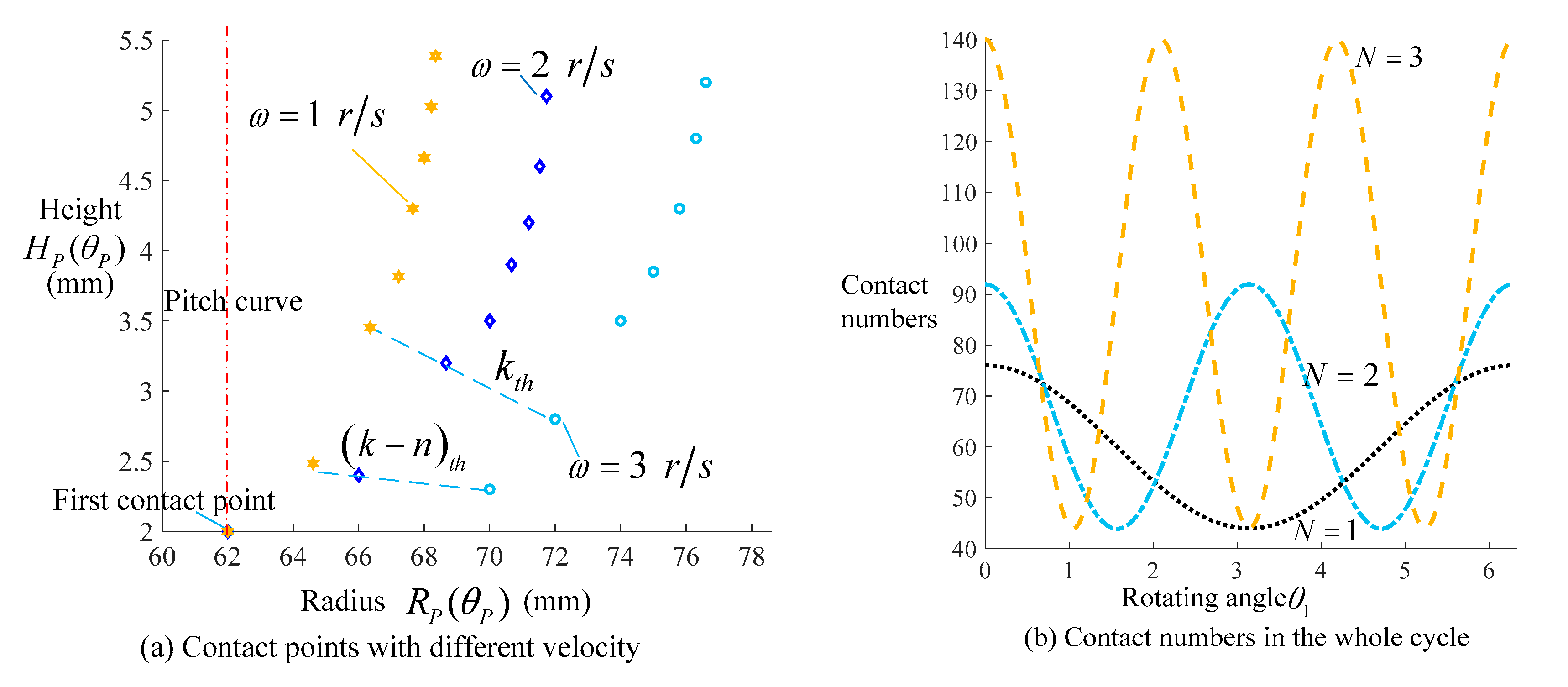
3.2. Interval-Separated Transmission Characteristics
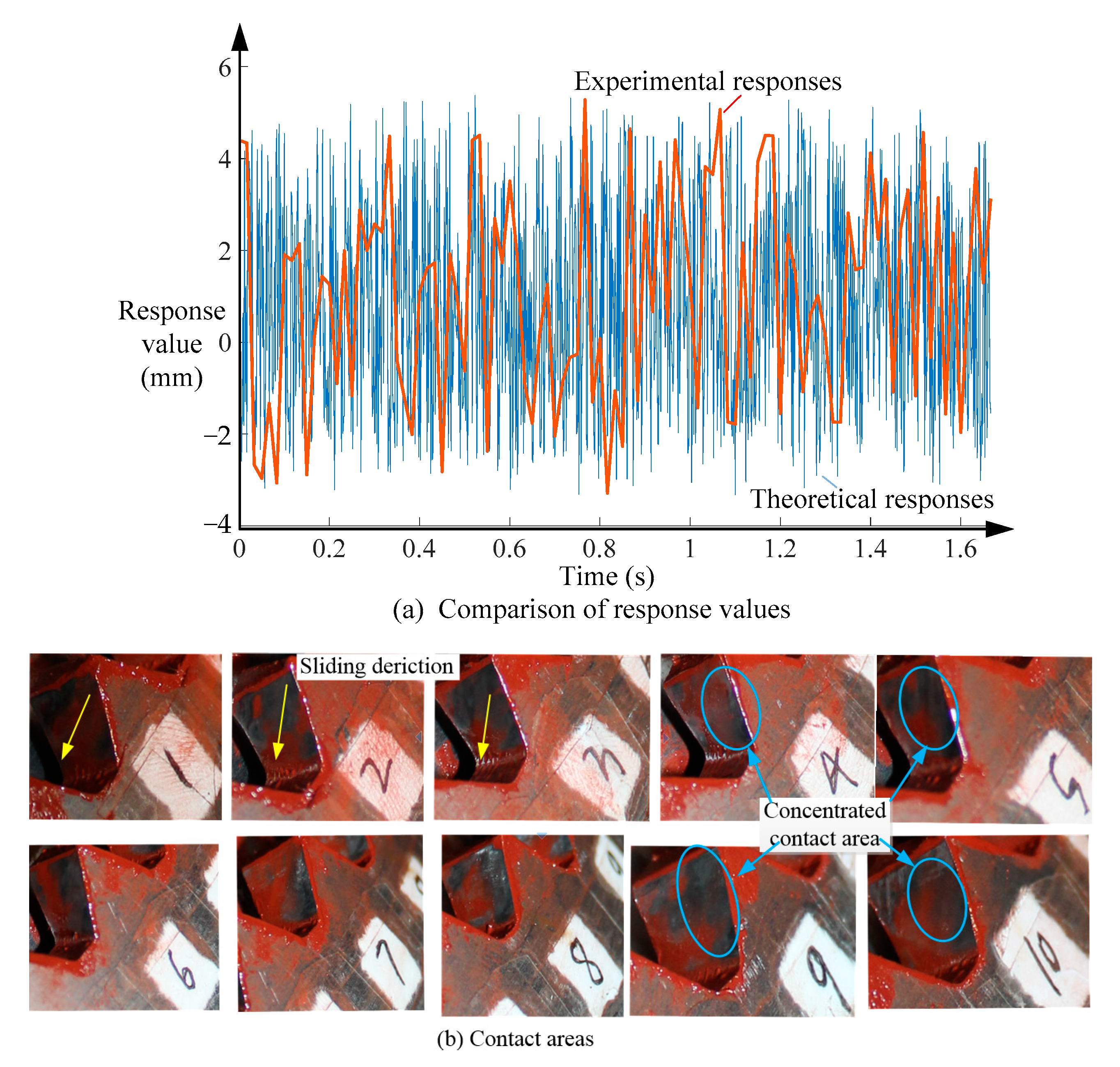
Figure 8, Figure 9 and Figure 10 show the free response characteristics of any ( k 1 ) t h collision, which appear at the separating time during any two adjacent collisions. The non-circular gear and the eccentric curve-face gear rotate at constant velocities during the separation time. Therefore, the k t h contact results from the following three situations: 1, the k t h contact point on the eccentric curve-face gear catches up with it on the non-circular gear; 2, the k t h contact point is created by the first spring-back collision of the coupling system; 3, the k t h contact point is created by the exact fit of the respective theoretical meshing points, as shown in Figure 11.
As demonstrated in Figure 11a,b, the governing equation for the k t h contact point is presented only by the contact between two rigid tooth surfaces with no embedding area, which no longer satisfies the pure meshing of the pitch curves as a normal gear pair. The pitch curves in situation 1 are detached, as are those in situation 2. Therefore, the relative sliding velocity v 31 is obvious and there must be conspicuous surface sliding in situations 1 and 2.
According to the mathematical Equations (6)–(9) and the response characteristics in Figure 7, Figure 8, Figure 9 and Figure 10 with different variable parameters, the responses of the spring system vary with time and position. In addition, the continuous collision transmission can be divided into the three situations in Figure 11. Therefore, there should be a critical angular velocity, with the sliding distance not exceeding the width of the tooth (described as R Z ( t ) < d G ) and the opposite tooth surface of the ( n + 1 ) t h tooth not meshing (shown as Δ ( t ) > 0 ) for this compound-motion gear pair to ensure a continuous meshing process. As shown in Figure 6, the width d G and thickness H G of the tooth are changeable with different radii R ( θ 1 ) . For good manufacturing performance, d G should be set as constant d . Thus, the boundary conditions for the correct meshing of this gear pair can be presented as follows:
R Z n ( t ) d 0 Δ t r P ( θ 3 n + ω 3 t ) d t = 0 Δ t R P ( θ 1 + ω 1 t ) d t 0 Δ t r P ( θ 3 n θ os n + 1 θ s n + 1 + ω 3 t ) d t H G n + 1 + 0 Δ t R P ( θ 1 + ω 1 t ) d t
where superscript n is the tooth number; Δ t is the interval time between the ( n + 1 ) t h and n t h collision.
The interval time Δ t of the two adjacent collisions can be proposed by R P ( θ P ) = r n ( θ P ) without V P ( θ P ) = V n ( θ P ) , because of the relative displacement of this gear pair. The rotation angles θ 1 in matrices M O 3 O 3 , M O 3 O 2 and M O 2 O 2 should be updated to θ 1 + ω 1 Δ t with θ 2 = θ 2 + ω 2 Δ t , θ 3 = θ 3 + ω 3 Δ t . Substituting Equations (1) and (2) and R Z ( t ) into the above positional relationship equation, the n + 1 t h meshing point P n + 1 on the tooth surface of the curve-face gear with interval time Δ t can be constructed as
R n + 1 ( θ P + ω 1 Δ t ) = = sin δ sin ( θ P + ω 1 Δ t ) r n ( θ P + ω 1 Δ t ) 2 + r 2 2 r r n ( θ P + ω 1 Δ t ) sin λ cos ( θ P + ω 1 Δ t ) r bs + L n ( θ P + ω 1 Δ t ) R ( θ P + ω 1 Δ t ) cos ( λ + θ 3 + θ os θ s δ ) i 13 cos ( λ + θ 3 θ o 2 θ s ) r bs sin θ 2 sin ( λ + θ 3 θ os θ s δ ) + θ 2 cos ( λ + θ 3 θ os θ s ) sin δ cos ( θ P + ω 1 Δ t ) r n ( θ P + ω 1 Δ t ) 2 + r 2 2 r r n ( θ P + ω 1 Δ t ) sin λ + sin ( θ P + ω 1 Δ t ) r bs + L n ( θ P + ω 1 Δ t ) R ( θ P + ω 1 Δ t ) cos ( λ + θ 3 θ os θ s δ ) i 13 cos ( λ + θ 3 θ os θ s ) r bs cos θ 2 sin ( λ + θ 3 θ os θ s δ ) + θ 2 cos ( λ + θ 3 θ os θ s ) E ( θ P + ω 1 Δ t ) cos δ r n ( θ P + ω 1 Δ t ) 2 + r 2 2 r r n ( θ P + ω 1 Δ t ) sin λ r bs sin ( λ + θ 3 θ os θ s δ ) + θ s cos ( λ + θ 3 θ os θ s δ )                                                                                                                               1
where δ , λ , θ s , u s are the corresponding parameters of the curve-face gear at point P n + 1 .
The decomposition of point P n + 1 on the non-circular gear can be obtained using the same method as Equation (11).
r n + 1 ( θ P + ω 1 Δ t ) = = r bs cos ( θ os + θ s + θ 3 θ 2 ) ( θ os + θ s ) sin ( θ os + θ s + θ 3 θ 2 ) + L n ( θ P + Δ t ) cos ( θ 2 δ ) r bs cos ( θ os + θ s + θ 3 θ 2 ) + ( θ os + θ s ) sin ( θ os + θ s + θ 3 θ 2 ) + L n ( θ P + Δ t ) cos ( θ 2 δ ) u s 1
The interval time Δ t is derived as
R n + 1 ( θ P + ω 1 Δ t ) = r n + 1 ( θ P + ω 1 Δ t )
The normal vector V n + 1 ( θ P + ω 1 Δ t ) of F T at meshing point P n + 1 on the curve-face gear can be given as
R n + 1 ( θ P + ω 1 Δ t ) V n + 1 ( θ P + ω 1 Δ t ) = 0
Therefore, by combining Equations (11)–(14), the position and normal vector of the n + 1 t h contact point are solved. Additionally, the initial value of F T F N F Z α υ ρ and D Z ( 0 ) at point P n + 1 are proposed. Figure 12a indicates the change in contact points on the same tooth surface from root to top with the parameters in Table 1. Figure 12b demonstrates the numbers of contacts on the tooth surface in a whole meshing cycle of the eccentric curve-face gear pair.
Figure 12a shows the displacement of the contact point with different rotational velocities on the same tooth surface. The initial contact points of these three situations are coincident at the same theoretical positions. With velocity increases, the contact point will be closer to the outer part and the contact points become much denser. This shows that the contact point will move outward in the width direction firstly and quickly, followed by a rapid and dense movement in the height direction until disengagement. The contact numbers in Figure 12b were obtained with ω = 1.5 r / s , demonstrating that the eccentricity time N affects the numbers of contact points by increasing the initial force F Z ( 0 ) . Specifically, with radius R P ( θ P ) decreasing, the response distance becomes closer to the outer part and the contact numbers decreases. The meshing will break off with too large a response displacement S Z ( t ) d G at the minimum radius R G min firstly with the increase in velocity. According to Equation (13), the values of the interval space and interval time should be Δ d 0.3   m m and Δ t 5.6 × 10 4   s , with the maximum height of the eccentric curve-face gear set as H ( θ P ) = 12   m m , ultimately exhibiting dense contact points and obvious surface sliding on the contact area.

4. Experiments

According to the previous theoretical analysis, the transmission characteristics of the compound-motion eccentric curve-face gear can be expressed as a large number of intermittent contact points on the tooth surface and tiny intermittent response displacements between the two tooth surfaces of the gear pair. For the verification of these theoretical results, we performed two experiments: (1) surface engagement with pre-coating; (2) vibration detection of the non-circular gear.
Experiment 1 was focused on the verification of intermittent contact points and surface sliding on the tooth surface. During meshing, the paint at the contact points is removed and the tooth surface is exposed, while the paint with the pre-coating in the non-contact areas still remains, as shown in the red zone (detected displacement and torque are provided as Supplementary Materials). Experiment 2 was focused on the existence of tiny displacements. To reduce the installation complexity, there was some common equipment between the two experiments: for example, the load, the torque sensor, the drive motor, fixed blocks, etc. The main differences were the displacement sensor and light spring, which were added to obtain significant displacements in experiment 2. The spring in experiment 1 was strong to limit the response displacements for a good contact situation. The differences between the two experiments are indicated by a yellow border for experiment 2 and a blue border for experiment 1, as shown in Figure 13.
Based on the previous theoretical results, the critical rotating velocity of this experiment was limited to n = 380   r / min . The loads of the two experiments were 30   N m , 40   N m and 50   N m . The stiffnesses of the springs were 28   N / m m and 35   N / m m for experiment 1 and 20   N / m m and 15   N / m m for experiment 2. The rotating velocities of the drive motor were divided into two groups: 100 rpm, 240 rpm, 350 rpm for experiment 1 and 50 rpm, 100 rpm, 150 rpm for experiment 2. The displacement sensor was an LK-H050. The further parameters of the experimental eccentric curve-face gear were set as in Table 2.
The comparison between the theoretical results and experimental results are presented in Figure 14.
Figure 14a shows the comparison of response values between the theoretical and experimental results, restricted by the response rate of the detection system and the environmental vibration; most detected tiny displacement values were covered by environmental vibration, causing the frequencies of the effective experimental values to be much lower than those of the theoretical values. However, the ranges of these two values are the same and the concentration range of the theoretical values also corresponds to the range of measured values. The teeth, which are numbered 1–10 in Figure 14b, represent a half-cycle of the eccentric curve-face gear. The tooth marked 1 is the 1st tooth at the minimum radius R G i min , and the maximum radius R G i max appears at the 10th tooth. Figure 14b indicates that the contact areas on these tooth surfaces are concentrated on the outer part and the surface sliding is obvious from teeth 1 to 10 in the whole transmission process. Both the smooth areas between the obvious sliding lines and the varying wear at the outer part of the tooth surface indicate that free vibration of this coupling system exists. Further, the detected vibration values prove that the free vibration response cannot be completed with one reciprocating cycle before the next contact collision occurs, which is consistent with situations 1 and 2 in Figure 11.

5. Conclusions

In this study, we compared the conjugated tooth surfaces of an eccentric curve-face gear pair with those of a non-circular gear. We found that the effective surface and kinematic characteristics of this gear pair are different from those of a normal face gear pair. In detail, all the parameters, such as eccentricity time N , eccentricity distance d N , modulus m and pitch radius R ( θ 1 ) , affect the effective width of the generated tooth. Figure 3, Figure 4 and Figure 5, which are presented in Section 2, show that reducing the inner radius R G i will increase the area of the root cutting and that increasing the outer radius R G o will increase the width of the top sharpening, which is consistent with the previous research in Refs. [11,12]. The minimum effective tooth width W G min appeared at minimum radius R ( θ 1 ) , as shown by the 1st tooth in Figure 5 and Figure 6 with θ 1 = 0 ; the same result was found for the variable width in Ref. [30].
Due to the existence of eccentricity distance d N , a non-circular gear undergoes both rotational and radial motion concurrently. Therefore, the kinematic characteristics (response displacement, contact points and critical velocity) of this gear pair are different from those of a conventional gear pair, and they are mostly affected by the stiffness of the rigid–flexible coupling system. When the stiffness of the spring increases, the interval time Δ t and displacement S Z ( t ) decrease obviously, and the critical velocity n c v and collision number increase with more dense collision points, but there is no effect on the width and height of the tooth surface; the same results were obtained in Refs. [12,13,30].
The results in this paper indicate that the contact points of this gear pair are intermittent, with many tiny intervals, as proposed in Ref. [27]. The motion of a non-circular gear between any two adjacent collisions is combined with constant rotation and axial free intermittent vibration; the interval time Δ t is very small and is not equal to the time on any other collision point. There is also obvious surface sliding, which is caused by the combined force of contact forces F T and F T n , similar to Ref. [28]. Specifically, the theoretical analysis in this paper demonstrates that the intermittent contact response value of the gear pair is given by the interval space Δ d 0.3   m m and interval time Δ t 5.6 × 10 4   s ; also, the critical velocity should be n c v 380   r / min .
In conclusion, we established mathematical models for the tooth surface and kinematical characteristics of an eccentric curve-face gear pair, performed experiments with different parameters and compared the results with theoretical analysis, verifying the correctness of the theoretical analysis for a complex tooth surface with compound motion.
In the future, our mechanical design work will focus on a more compact, more concise, lighter and higher-efficiency domain. We will continue studying the prediction of tooth contact characteristics with compound transmission, considering different parameters (width, eccentric displacement, undulating times, modulus, etc.), based on the developed intermittent collision model. We also plan to establish a high-precision and scalable manufacturing method for the complex tooth surfaces of this gear type. We hope the results can be utilized to simplify the design of complex transmission mechanisms.

Supplementary Materials

The following supporting information can be downloaded at: https://www.mdpi.com/article/10.3390/machines12030162/s1, Table S1: detected displacement; Table S2: detected torque.

Author Contributions

Methodology, C.H. and J.Z.; software, C.H. and C.L.; formal analysis, C.H.; investigation, C.H. and J.Z.; writing—original draft preparation, C.H. and J.Z.; writing—review and editing, C.L. All authors have read and agreed to the published version of the manuscript.

Funding

This research was funded by the Postdoctoral Research Project, grant number 202300054; the Science Fund Project of Chongqing University of Science and Technology, grant number ckrc2021006; and the Science and Research Program of Chongqing Municipal Education Commission, grant number KJQN202101514.

Data Availability Statement

Data available on request due to restrictions.

Acknowledgments

The authors would like to thank the Postdoctoral Research Project, the Science Fund Project of Chongqing University of Science and Technology and the Science and Research Program of Chongqing Municipal Education Commission for their financial support in this research.

Conflicts of Interest

The authors declare no conflicts of interest.

References

  1. Nirala, A.; Kumar, N.; Singh, D.B.; Singh, A.K.; Sharma, S.K.; Yadav, J.K.; Prasad, H.; Chandan, S.; Shrivastava, A.K. Simulation analysis of composite helical spring for compression, torsional and transverse mode. Mater. Today-Proc. 2020, 28, 2263–2267. [Google Scholar] [CrossRef]
  2. Michalczyk, K. Natural transverse vibrations of helical springs in sections covered with elastic coatings. Bull. Pol. Acad. Sci.-Tech. Sci. 2018, 65, 949–959. [Google Scholar] [CrossRef]
  3. Gu, Z.W.; Hou, X.N.; Ye, J.Q. Design and analysis method of nonlinear helical springs using a combining technique: Finite element analysis, constrained Latin hypercube sampling and genetic programming. Proc. Inst. Mech. Eng. Part C-J. Mech. Eng. Sci. 2021, 235, 5917–5930. [Google Scholar] [CrossRef]
  4. Yang, C.J.; Zhang, W.H.; Ren, G.X.; Liu, X.Y. Modeling and dynamics analysis of helical spring under compression using a curved beam element with consideration on contact between its coils. Meccanica 2014, 49, 907–917. [Google Scholar] [CrossRef]
  5. Hamza, A.; Ayadi, S.; Hadj-Taieb, E. Propagation of strain waves in cylindrical helical springs. J. Vib. Control 2015, 21, 1914–1929. [Google Scholar] [CrossRef]
  6. Renno, J.M.; Mace, B.R. Vibration modelling of helical springs with non-uniform ends. J. Sound Vib. 2012, 331, 2809–2823. [Google Scholar] [CrossRef]
  7. Zhou, C.J.; Hu, B.; Chen, S.Y.; He, L.P. An enhanced flexible dynamic model and experimental verification for a valve train with clearance and multi-directional deformations. J. Sound Vib. 2017, 410, 249–268. [Google Scholar] [CrossRef]
  8. Pawar, H.B.; Desale, D.D. Optimization of Three Wheeler Front Suspension Coil Spring. Procedia Manuf. 2018, 20, 428–433. [Google Scholar] [CrossRef]
  9. Gu, Z.W.; Hou, X.N.; Keating, E.; Ye, J.Q. Non-linear finite element model for dynamic analysis of high-speed valve train and coil collisions. Int. J. Mech. Sci. 2020, 173, 105476. [Google Scholar] [CrossRef]
  10. Baran, R.; Michalczyk, K.; Warzecha, M. Experimental Analysis of Transverse Distribution Stiffness of Helical Compression Springs. Acta Mech. Autom. 2023, 17, 95–103. [Google Scholar] [CrossRef]
  11. Lin, C.; Liu, Y. Characteristic analysis and application of composite motion curve-face gear pair. J. Braz. Soc. Mech. Sci. Eng. 2016, 38, 1797–1804. [Google Scholar] [CrossRef]
  12. Lin, C.; Liu, Y.; Gu, S.J. Analysis of nonlinear twisting vibration characteristics of orthogonal curve-face gear drive. J. Braz. Soc. Mech. Sci. Eng. 2015, 37, 1499–1505. [Google Scholar] [CrossRef]
  13. He, C.J.; Lin, C. Analysis of loaded characteristics of helical curve-face gear. Mech. Mach. Theory 2017, 115, 267–282. [Google Scholar] [CrossRef]
  14. Liu, D.W.; Ren, T.Z.; Jin, X. Geometrical model and tooth analysis of undulating face gear. Mech. Mach. Theory 2015, 86, 140–155. [Google Scholar] [CrossRef]
  15. Temirkhan, M.; Bin, T.H.; Spitas, V.; Spitas, C. Parametric design of straight bevel gears based on a new tooth contact analysis model. Arch. Appl. Mech. 2023, 93, 4181–4196. [Google Scholar] [CrossRef]
  16. Temirkhan, M.; Spitas, C.; Wei, D.M. A computationally robust solution to the contact problem of two rotating gear surfaces in space. Meccanica 2023, 58, 2455–2466. [Google Scholar] [CrossRef]
  17. Shaabidov, S.A.; Irgashev, B.A. Computational Procedure of a Gearing Module of Spur Gear Transmissions on Wear Resistance of Gearwheel Teeth. J. Frict. Wear 2019, 40, 431–436. [Google Scholar] [CrossRef]
  18. Xiao, Z.M.; Cao, J.X.; Yu, Y.X. Mathematical Modeling and Dynamic Analysis of Planetary Gears System with Time-Varying Parameters. Math. Probl. Eng. 2020, 2020, 3185624. Available online: https://www.hindawi.com/journals/mpe/2020/3185624/ (accessed on 16 March 2020). [CrossRef]
  19. Jasem, M.A.; Krauinsh, P.Y. Introduction of a wave face kinematic reducer in pumping technologies for the extraction of high-viscous oil in extreme conditions. Bull. Tomsk. Polytech. Univ.-Geo Assets Eng. 2022, 333, 45–53. [Google Scholar]
  20. Xie, C.Y.; Yu, W. Gear dynamic modelling based on the concept of dynamic mesh stiffness: Theoretical study and experimental verification. J. Mech. Sci. Technol. 2022, 36, 4953–4965. [Google Scholar] [CrossRef]
  21. Wang, Q.B.; Ma, H.B.; Kong, X.G. A distributed dynamic mesh model of a helical gear pair with tooth profile errors. J. Central South Univ. 2018, 25, 287–303. [Google Scholar] [CrossRef]
  22. Wang, Z.G.; Lo, C.C.; Chen, Y.C. Comparison and Verification of Dynamic Simulations and Experiments for a Modified Spur Gear Pair. Machines 2022, 10, 191. [Google Scholar] [CrossRef]
  23. He, Z.Y.; Lin, T.J.; Chen, C.J. Mathematical models and dynamic contact analysis of involute/noninvolute beveloid gears. J. Vibroeng. 2014, 16, 2946–2961. [Google Scholar]
  24. He, X.Z.; Zhou, X.Q.; Xue, Z.; Hou, Y.X.; Liu, Q.; Wang, R.Q. Effects of gear eccentricity on time-varying mesh stiffness and dynamic behavior of a two-stage gear system. J. Mech. Sci. Technol. 2019, 33, 1019–1032. [Google Scholar] [CrossRef]
  25. Yu, X.; Sun, Y.Y.; Li, H.G.; Wu, S.J. Nonlinear characteristics of gear pair considering fractal surface dynamic contact as internal excitation. Int. J. Non-Linear Mech. 2022, 143, 104027. [Google Scholar] [CrossRef]
  26. He, C.Y.; Chen, Z.G.; Zhai, W.M.; Jiang, J.Z.; Wang, K.Y. A spatial dynamics model for heavy-haul electric locomotives considering the dynamic coupling effect of gear transmissions. Proc. Inst. Mech. Eng. Part F-J. Rail Rapid Transit 2019, 233, 961–973. [Google Scholar] [CrossRef]
  27. Spitas, C.; Spitas, V. Coupled multi-DOF dynamic contact analysis model for the simulation of intermittent gear tooth contacts, impacts and rattling considering backlash and variable torque. Proc. Inst. Mech. Eng. Part C-J. Mech. Eng. Sci. 2016, 230, 1022–1047. [Google Scholar] [CrossRef]
  28. Marjanovic, N.; Ivkovic, B.; Blagojevic, M.; Stojanovic, B. Experimental determination of friction coefficient at gear drives. J. Balk. Tribol. Assoc. 2010, 16, 517–526. [Google Scholar]
  29. Litvin, F.L. Gear Geometry and Applied Theory, 2nd ed.; Cambridge University: New York, NY, USA, 2004. [Google Scholar] [CrossRef]
  30. Lin, C.; Wu, X.Y. Calculation and Characteristic Analysis of Tooth Width of Eccentric Helical Curve-Face Gear. Iran. J. Sci. Technol.-Trans. Mech. Eng. 2019, 43, 781–797. [Google Scholar] [CrossRef]
Figure 1. Engaged tooth surface of eccentric curve-face gear. (a) Conjugate meshing of the three gears; (b) relationship between non-circular gear and shaping tool.
Machines 12 00162 g001
Figure 2. Engagement relationship of the three tooth surfaces.
Machines 12 00162 g002
Figure 3. Divisions of tooth surface.
Machines 12 00162 g003
Figure 4. Cutting height with different times N .
Machines 12 00162 g004
Figure 5. Effective width with different parameters.
Machines 12 00162 g005
Figure 6. Response force of rigid–flexible coupling system.
Machines 12 00162 g006
Figure 7. Free response with different stiffness values.
Machines 12 00162 g007
Figure 8. Free response with different rotating velocity values.
Machines 12 00162 g008
Figure 9. Free response with different initial force values.
Machines 12 00162 g009
Figure 10. Stacked vibration with meshing.
Machines 12 00162 g010
Figure 11. Separate models of coupling system.
Machines 12 00162 g011
Figure 12. Collision contacts on tooth surface.
Machines 12 00162 g012
Figure 13. Experimental meshing.
Machines 12 00162 g013
Figure 14. Comparison between theoretical and experimental results.
Machines 12 00162 g014
Table 1. Variable parameters of eccentric curve-face gear pair.
ParameterRange ParameterRange
Base   radius   of   eccentric   curve-face   gear   R ( θ 1 ) (mm)70–72Eccentricity times N 1, 2, 3
Width d 1 of eccentric curve-face gear (mm)8–20Eccentricity distance d N (mm)5–10
Undulating times n 2, 3, 4Range of height E ( θ 1 ) (mm)6–12
Tooth number Z of shaping tool18, 20, 22Modulus m 1, 1.25, 1.5
Radius r  of shaping tool (mm)18–44Width d 2 of shaping tool (mm)8–20
Table 2. Experimental parameters of eccentric curve-face gear.
ParameterValueParameterValue
Minimum base radius R P ( θ P ) (mm)60Eccentricity times N 1
Undulating times n 4Eccentricity distance d N (mm)7
Tooth number Z of shaping tool18Range of height E ( θ 1 ) (mm)8
Width d 2 of shaping tool (mm)20Modulus m (mm)4
Disclaimer/Publisher’s Note: The statements, opinions and data contained in all publications are solely those of the individual author(s) and contributor(s) and not of MDPI and/or the editor(s). MDPI and/or the editor(s) disclaim responsibility for any injury to people or property resulting from any ideas, methods, instructions or products referred to in the content.

