
Temperature Prediction for 3 MW Wind-Turbine Gearbox Based on Thermal Network Model

Abstract
1. Introduction
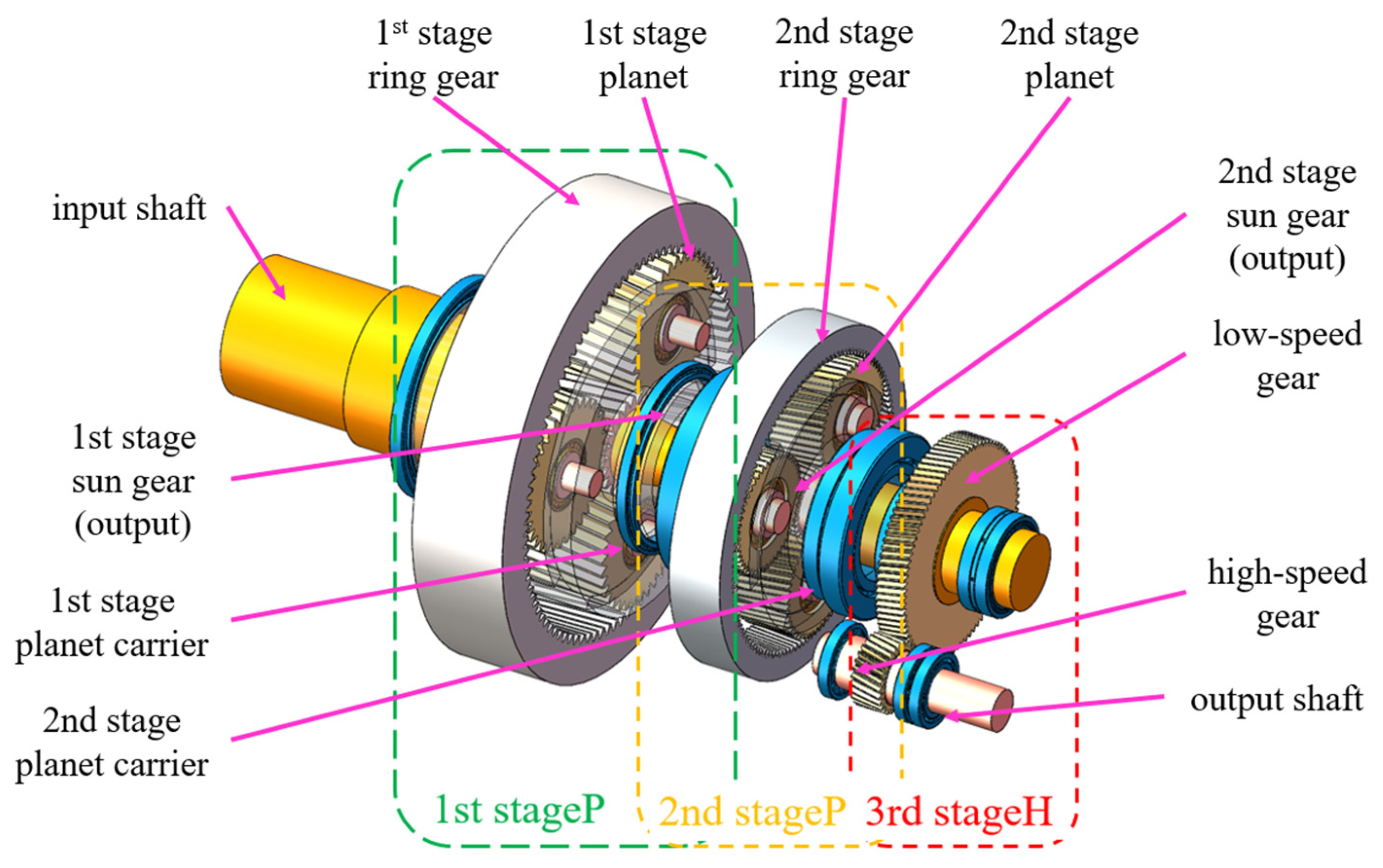
2. Principles of Transmission and Temperature Monitoring in 3 MW Wind-Turbine Gearboxes
3. Thermal Network Model Construction
3.1. Thermodynamic Analysis of the Interior of a Wind-Turbine Gearbox
3.2. Node Selection and Thermal Network Diagram Construction
3.3. Formulation and Solution of the Thermal Equilibrium Equations at the Nodes
4. Calculation of Parameters for Steady-State Temperature Solution of the Gearbox
4.1. Analysis and Calculation of Gear Meshing Power Loss
- (1)
- Calculation formulas for sliding friction loss in gear meshing.Formula for calculating the length of the meshing line:Formulas for calculating the average sliding velocity and average rolling velocity:Formula for calculating the average normal load:Formula for calculating the friction coefficient:Formula for calculating the average sliding loss:
- (2)
- Formulas for calculating meshing rolling friction loss.Curvature radius calculation formula:Formula for calculating the oil film thickness:Formula for calculating the overlap ratio:Formula for calculating the average rolling loss:Summing up, the total power loss of gear meshing can be calculated:
4.2. Analysis and Calculation of Bearing Operating Power Loss
4.3. Calculation of Thermal Resistance and Convective Heat-Transfer Coefficient
4.3.1. Calculation of Thermal Conductive Resistance
4.3.2. Calculation of Convective Heat Transfer Resistance [21]
- (1)
- Convective heat transfer between the casing outer wall and air.
- (2)
- Convective heat transfer computation for the bearings and lubricating oil.
- (3)
- Heat transfer resistance between the gears and lubricating oil.
- (4)
- Casing and lubricating oil convective heat transfer calculation.
5. Steady-State Temperature Calculation and Result Validation in the Gearbox
5.1. Programming Calculation and Results
5.2. Comparative Validation of the Thermal Network Model’s Efficacy
- (1)
- Errors stemming from the node simplification: The thermal network model simplifies components like gear bearings into ideal nodes for computation. In practical scenarios, heat generation points in bearing positions may be at the contact points of rollers and other components, whereas the thermal network model treats the entire bearing node as a heat source.
- (2)
- Errors arising from the lubrication system simplification: In actual lubrication processes, the lubricating oil flows out of the gearbox for secondary cooling. Moreover, the lubricating oil temperatures at different positions in the gearbox should be varied, and the oil-spray quantities should be adjusted in real time based on the gearbox temperature conditions. However, for computational efficiency, the thermal network model simplifies the lubricating oil temperature and spray parameters as ideal conditions.
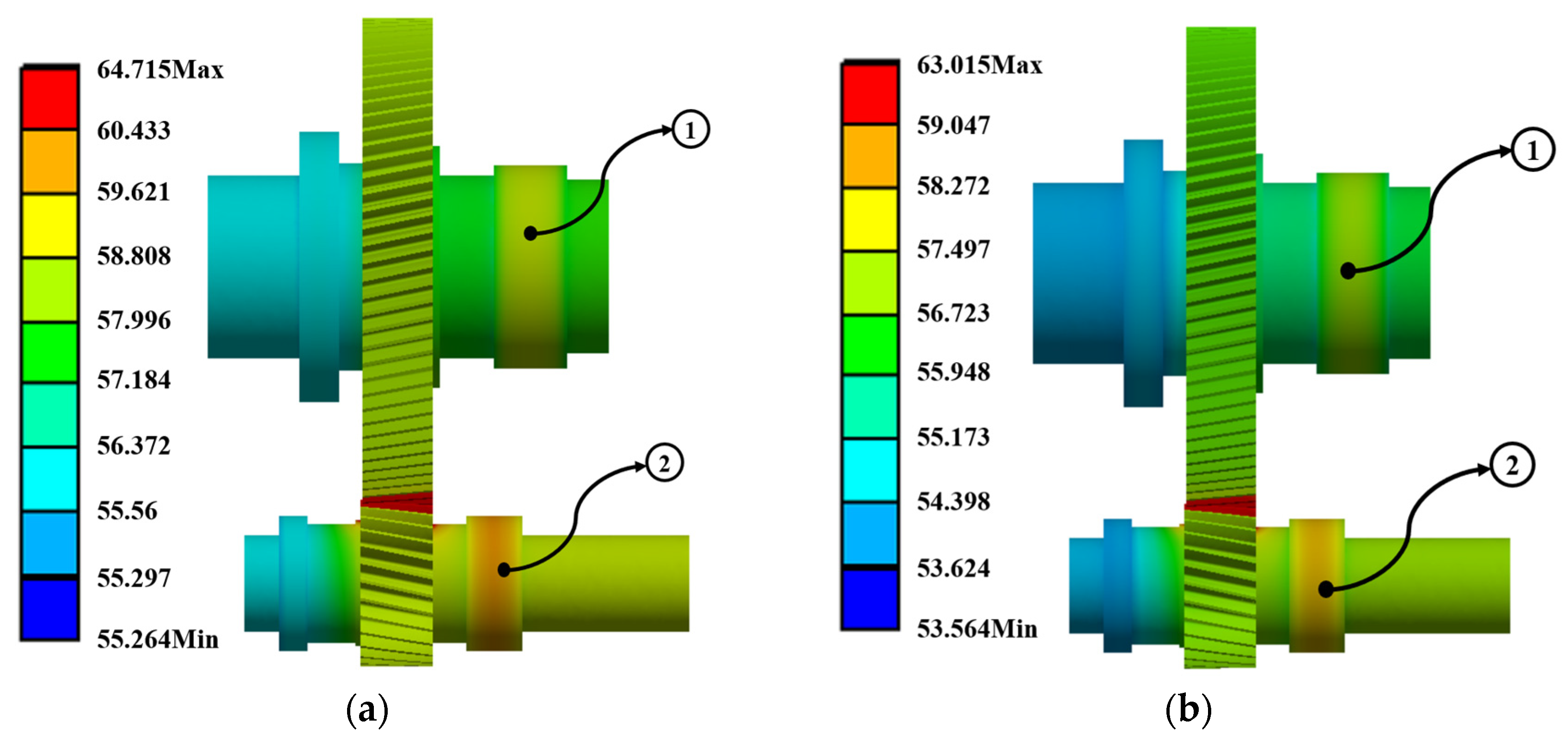
5.3. Finite Element Simulation Validation of the Thermal Network Model’s Efficacy
5.4. Conclusion of Thermal Network Model Verification
6. Exploring the Influence of Oil Injection Parameters on the Steady-State Temperature Field
7. Conclusions
- (1)
- Under various high-temperature conditions, temperature forecasts for the 3 MW wind-turbine gearbox revealed a concentrated distribution of internal high-temperature nodes within the third stage. Node 41 (high-speed downwind bearing—deep groove ball bearing) stands out as the hottest point within the gearbox, notorious for its frequent high-temperature failures. Similarly, under substantial input loads, Node 15 (meshing area of first-stage planetary-gear sun gear) experiences elevated temperatures, making it prone to gear failures such as bonding. To avert downtime caused by high temperatures, it is essential to enhance lubrication and cooling mechanisms at these critical nodes, optimize mechanical structures, and prioritize the monitoring of high-temperature failures.
- (2)
- Through comparison with SCADA data, the average error of the thermal network model in this study ranges from 1 to 4 °C. When the turbine operates steadily, the average error decreases to 1 to 2 °C. However, significant fluctuations in turbine input power can lead to increased errors. Hence, for temperature prediction, it is advisable to analyze the turbine’s operation during stable or gradually changing conditions.
- (3)
- Through analysis of the oil spray parameters, it is evident that the diameter and velocity of the oil spray significantly impact the internal temperature of the gearbox, showing a trend where cooling effectiveness increases with the enlargement of these parameters. Conversely, the spray angle exerts minimal influence on temperature. Therefore, in designing the oil-spray system, greater emphasis should be placed on optimizing velocity and diameter parameters, while the spray angle can be tailored based on gearbox structure for optimal design. Moreover, these parameters can be integrated into the model presented in this paper to validate the optimization outcomes.
Author Contributions
Funding
Data Availability Statement
Acknowledgments
Conflicts of Interest
References
- Ding, Y.T. Central People’s Government of the People’s Republic of China. Available online: https://www.gov.cn/xinwen/2023-02/14/content_5741415.htm (accessed on 10 January 2023).
- Xiang, D.; Wei, Y.Z.; Shen, Y.H.; Sun, X.Y. Research on thermal network modeling and temperature calculation method for wind turbine gearbox lubrication oil temperature overrun fault. J. Mech. Eng. 2022, 58, 17. [Google Scholar]
- Zhao, W.; Jiang, Z.; Zhang, P.; Huang, X. Reliability sensitivity analysis of main shaft bearings of wind turbines subject to subsurface stress. Machines 2023, 11, 681. [Google Scholar] [CrossRef]
- Xu, Z.J.; Xue, Y.Y.; Yang, Y.J.; Xing, Z.X. Cause analysis and solving measures of high oil temperature in a series of wind turbine gearboxes. Acta Energ. Sol. Sin. 2020, 41, 74–79. [Google Scholar]
- Zhao, W.D. Analysis on the treatment of high temperature problems in the gearbox of wind turbines. Electron. Technol. 2023, 52, 236–237. [Google Scholar]
- Liu, B.; Liu, B.; Wan, Q.; Lu, C.P.; Chen, B.Z.; Cheng, J.X.; Chen, B. Research on heat dissipation of wind turbine gearbox engine room based on fluent. Resour. Inf. Eng. 2023, 38, 108–113. [Google Scholar]
- Huang, Z.S.; Tian, L.; Xiang, D.; Wei, Y.Z. Prediction of oil temperature variations in a wind turbine gearbox based on PCA and an SPC-dynamic neural network hybrid. Tsinghua Sci. Technol. 2018, 58, 539–546. [Google Scholar]
- Gu, Y.J.; Su, L.W.; Zhong, Y.; Xu, T. An online fault early warning method for wind turbine gearbox based on operational condition division. Energy Sci. Eng. 2014, 30, 1. [Google Scholar]
- Jing, T.M.; Qi, Y.S.; Liu, L.Q. Condition monitoring and health assessment of wind turbine gearbox based on KECA-GRNN. Acta Energ. Sol. Sin. 2021, 42, 400–408. [Google Scholar]
- He, Q.; Li, Y.Y.; Jiang, G.Q.; Su, N.; Xie, P.; Wu, X. Health assessment of wind turbine gearbox based on conditional convolution autoencoding gaussian mixture model. Acta Energ. Sol. Sin. 2023, 44, 214–220. [Google Scholar]
- Song, H.; Ahmat, M.; Yusup, N.; Wang, Y.H.; Zhang, Q.Y. Study on transient temperature of wind turbine bearing based on thermal network and numerical simulation. Bearing 2022, 6, 51–58. [Google Scholar]
- Liu, Y.; Zhang, K.L.; Shao, S.; Xiang, H.X. Investigation on steady-state thermal performance of gear box based on thermal–fluid-solid coupling. J. Shanghai Jiao Tong Univ. 2024, 1–17. [Google Scholar] [CrossRef]
- Deshpande, S.; Joshi, H.; Madhavan, J.; Mason, P.; Wink, C. Two-way coupled CFD approach for predicting gear temperature of oil jet lubricated transmissions. SAE Int. J. Commer. Veh. 2018, 11, 163–170. [Google Scholar] [CrossRef]
- Fan, Y. Thermal Analysis and Flow Field Simulation of an Unmanned Helicopter Main Gearbox. Master’s Thesis, Nanjing University of Aeronautics and Astronautics, Nanjing, China, 2019. [Google Scholar]
- Liu, Y.; Peng, J.; Wang, B.; Qin, D.; Ye, M. Bulk temperature prediction of a two-speed automatic transmission for electric vehicles using thermal network method and experimental validation. Proc. Inst. Mech. Eng. Part D J. Automob. Eng. 2019, 233, 2585–2598. [Google Scholar] [CrossRef]
- Kang, Q.; Li, S.W.; Guo, J.L. The thermal network method outline. Ind. Heat. 2006, 35, 15–18. [Google Scholar]
- Xu, X.; Bi, X.P. Computer simulation and calculation of heat transfer in automotive gearbox. J. Mech. Transm. 2003, 27, 1–4. [Google Scholar] [CrossRef]
- SKF. SKF Rolling Bearing Catalog; SKF Group: Gothenburg, Sweden, 2016. [Google Scholar]
- Kahraman, A.; Hilty, D.; Singh, A. An experimental investigation of spin power losses of a planetary gear set. Mech. Mach. Theory 2015, 86, 48–61. [Google Scholar] [CrossRef]
- Wang, Z.H. Practical Bearing Manual, 2nd ed.; Shanghai Scientific and Technological Literature Press: Shanghai, China, 1996; pp. 1–304. [Google Scholar]
- Huang, F. The Thermal Analysis of Epicyclic Gear Reducer Based on Thermal Network Method. Master’s Thesis, Nanjing University of Aeronautics and Astronautics, Nanjing, China, 2011. [Google Scholar]
- Xiang, C. Thermal Balance Analysis of High Speed Gearbox of Electric Vehicle Based on Thermal Network Structure. Master’s Thesis, Chongqing University, Chongqing, China, 2018. [Google Scholar]
- Mo, S.; Li, X.; Zou, Z.X.; Feng, Z.Y.; Cen, G.J.; Huang, Y.S. Analysis and research of asymmetric helical gear oil injection lubrication considering convective heat transfer coefficient. J. Mechl. Transm. 2022, 46, 1–6+37. [Google Scholar]
- Liu, R.R. Windage Analysis and Oil Jet Lubrication Simulation of High Speed Double Helical Star Gear System. Master’s Thesis, Chongqing University, Chongqing, China, 2021. [Google Scholar]
- Li, J.D.; Feng, J.; Liu, X.F.; Qin, K. Flow simulation analysis of multi channel lubrication system of certain gear box test bench. Mechl. Eng. Autom. 2020, 49, 7–9. [Google Scholar]


| Location | Module (mm) | Number of Teeth | Pressure Angle (°) | Helix Angle (°) | |
|---|---|---|---|---|---|
| First-stage planetary | Sun gear | 19.1 | 22 | 22.5 | 6.1 |
| Planet gear | 19.1 | 35 | 22.5 | 6.1 | |
| Internal gear | 19.1 | 94 | 22.5 | 6.1 | |
| Second-stage planetary | Sun gear | 11 | 27 | 20 | 6.8 |
| Planet gear | 11 | 49 | 20 | 6.8 | |
| Internal gear | 11 | 126 | 20 | 6.8 | |
| High-speed parallel | Large gear | 11 | 89 | 20 | 11.5 |
| Small gear | 11 | 28 | 20 | 11.5 | |
| Bearing Name | Location | Bearing Type | Outer Diameter (mm) | Inner Diameter (mm) | Width (mm) |
|---|---|---|---|---|---|
| NNCF 5044CVs | First-stage planetary | Cylindrical roller | 340 | 220 | 160 |
| EE763330 | First-stage upwind | Tapered roller | 1041.4 | 838.2 | 93.663 |
| LL483449 | First-stage downwind | Tapered roller | 889 | 762 | 69.85 |
| 60/670NIMAS | Second-stage upwind | Deep groove ball | 980 | 670 | 136 |
| Nu1044M | Second-stage planetary | Cylindrical roller | 220 | 340 | 56 |
| 294/500EM | Second-stage downwind | Spherical roller thrust | 500 | 870 | 224 |
| NU1076 | Low-speed upwind | Cylindrical roller | 380 | 560 | 82 |
| 32972/DF | Low-speed downwind | Face-to-face tapered roller | 360 | 480 | 152 |
| NU240ECM | High-speed upwind/downwind | Cylindrical roller | 200 | 360 | 58 |
| QJ240N2MA | High-speed downwind | Angular contact ball | 200 | 360 | 58 |
| Data | Time | Bearing Temperature in the Gearbox (°C) | Gearbox Oil Temperature (°C) | Temperature Inside the Nacelle (°C) |
|---|---|---|---|---|
| 13 October 2021 | 23:53:15 | 50.7 | 51.7 | 21.8 |
| 14 October 2021 | 0:03:15 | 50.2 | 51.4 | 21.8 |
| 14 October 2021 | 0:13:15 | 51 | 51.4 | 21.6 |
| 14 October 2021 | 0:23:15 | 51 | 51.5 | 21.5 |
| Node Number | Node Location |
|---|---|
| 1 | External air of gearbox |
| 2 | Internal air of gearbox |
| 3 | Gearbox internal oil pool |
| 4 | Input shaft—left |
| 5 | First-stage left casing |
| 6 | First-stage planetary gear |
| 7 | First-stage planetary gear shaft |
| 8 | Meshing area of first-stage planetary-gear internal ring |
| 9 | First-stage internal ring |
| 10 | First-stage planetary gear bearing |
| 11 | First-stage right casing |
| 12 | First-stage sun gear shaft |
| 13 | First-stage downwind bearing |
| 14 | First-stage planetary carrier—right |
| 15 | Meshing area of first-stage planetary-gear sun gear |
| 16 | First-stage sun gear |
| 17 | First-stage planetary carrier—left |
| 18 | First-stage upwind bearing |
| 19 | Input shaft—right |
| 20 | First-stage bearing sleeve |
| 21 | Second-stage left casing |
| 22 | Meshing area of second-stage planetary-gear internal gear |
| 23 | Second-stage planetary gear bearing |
| 24 | Second-stage planetary gear |
| 25 | Second-stage internal gear |
| 26 | Second-stage planetary gear shaft |
| 27 | Second-stage sun gear shaft |
| 28 | Second-stage downwind bearing |
| 29 | Second-stage planetary carrier—right |
| 30 | Meshing area of second-stage planetary-gear sun gear |
| 31 | Second-stage sun gear |
| 32 | Second-stage planetary carrier—left |
| 33 | Second-stage upwind bearing |
| 34 | Second-stage right casing |
| 35 | High-speed upwind bearing |
| 36 | High-speed gear |
| 37 | High-speed shaft—left |
| 38 | Third-stage gearbox |
| 39 | High-speed downwind bearing—cylindrical roller bearing |
| 40 | High-speed shaft—right |
| 41 | High-speed downwind bearing—deep groove ball bearing |
| 42 | Meshing area of high-speed gear |
| 43 | Low-speed upwind bearing |
| 44 | Low-speed shaft—left |
| 45 | Low-speed shaft—right |
| 46 | Low-speed downwind bearing |
| 47 | Bearing end cover of 2–3 stages |
| 48 | Low-speed gear |
| Symbol | Symbolic Meaning | Unit |
|---|---|---|
| The heat generation rate per unit volume in node n | W/m³ | |
| A function of the temperature | ||
| The thermal resistance between nodes j and n | ||
| C | The specific heat capacity | J/(kg·K) |
| Δt | The time interval from time i to i + 1 | |
| A | Thermal resistance matrix | |
| T | Temperature node matrix | |
| Q | Heat source matrix | |
| Z | Constant matrix in the heat balance equation | |
| Addendum circle radius | m | |
| Base circle radius of the gear | m | |
| Root circle radius of the gear | m | |
| Face pressure angle | ° | |
| Number of teeth | ||
| Rotational speed of the driving wheel | r/min | |
| Input torque | N·m | |
| Base circle pressure angle | ° | |
| Lubricating oil dynamic viscosity | MPa·s | |
| Average sliding loss of the gear | kW | |
| Tooth thickness | mm | |
| Bearing power loss | kW | |
| Relative speed between the inner and outer rings of the Bearing | r/min | |
| Running resistance torque of the bearing | N·mm | |
| Inlet shear heat shrinkage coefficient | ||
| Motion compensation reduction coefficient | ||
| Lubricating oil kinematic viscosity; | 10−6 m2/s | |
| Depends on the motion state | ||
| The specific values of these parameters depend on the Type of bearing | ||
| Contact area | m2 | |
| Meshing point sliding velocity | m/s | |
| Gear pitch circle point sliding velocity | m/s | |
| Thermal conductivity of the gear material | W/(m·K) | |
| Convective heat transfer coefficient | W/(m²·K) | |
| Characteristic length/radius (diameter) | m | |
| Convective heat transfer coefficient | ||
| Convective heat transfer coefficient for cylindrical surfaces | ||
| Convective heat transfer coefficient for vertical surfaces | ||
| Depends on the properties of the lubricating oil | ||
| Prandtl number | ||
| Air thermal conductivity | W/(m·k) | |
| Coefficient of air expansion | ||
| Air dynamic viscosity | m2/s | |
| Bearing cage speed | r/min | |
| Nusselt number | ||
| Specific heat at constant pressure | J/(kg·K) | |
| Lubricating oil flow characteristics | m/s | |
| Lubricating oil dynamic viscosity | mm/s | |
| Lubricating oil thermal conductivity | W/(m·K) | |
| Oil-injection nozzle area | m2 | |
| Cooling area | m2 | |
| Oil injection angle | ° | |
| Injection velocity | m/s |
| Time | Nacelle Temperature (°C) | Gearbox Oil Temperature (°C) | High-Speed Shaft Bearing Temperature (°C) | |
|---|---|---|---|---|
| Scenario 1 | 12 June 2021 11:50 | 40.8 | 54.5 | 63.1 |
| Scenario 2 | 12 June 2021 12:00 | 40.8 | 52.8 | 62.2 |
| Scenario 3 | 12 July 2021 14:59 | 40.5 | 52.4 | 63.8 |
| Scenario 4 | 12 July 2021 15:29 | 39.6 | 50.3 | 64 |
| Scenario 5 | 12 August 2021 2:28 | 26 | 53 | 63 |
| Scenario 6 | 12 August 2021 2:38 | 25.8 | 50.9 | 61.5 |
| Temperature at Point 1 (°C) | Temperature at Point 2 (°C) | Highest Temperature (°C) | Lowest Temperature (°C) | |
|---|---|---|---|---|
| Scenario 1 | 60.112 | 58.783 | 64.715 | 55.264 |
| Scenario 2 | 58.3 | 57.097 | 63.015 | 53.564 |
| Scenario 3 | 57.99 | 56.695 | 62.615 | 53.164 |
| Scenario 4 | 55.963 | 54.55 | 60.515 | 51.064 |
| Scenario 5 | 58.152 | 57.284 | 63.215 | 53.764 |
| Scenario 6 | 56.388 | 55.185 | 61.115 | 51.664 |
Disclaimer/Publisher’s Note: The statements, opinions and data contained in all publications are solely those of the individual author(s) and contributor(s) and not of MDPI and/or the editor(s). MDPI and/or the editor(s) disclaim responsibility for any injury to people or property resulting from any ideas, methods, instructions or products referred to in the content. |
© 2024 by the authors. Licensee MDPI, Basel, Switzerland. This article is an open access article distributed under the terms and conditions of the Creative Commons Attribution (CC BY) license (https://creativecommons.org/licenses/by/4.0/).
Share and Cite
Cui, Y.-F.; Zhang, Y.-H.; He, W.-D.; Dong, L.-J. Temperature Prediction for 3 MW Wind-Turbine Gearbox Based on Thermal Network Model. Machines 2024, 12, 175. https://doi.org/10.3390/machines12030175
Cui Y-F, Zhang Y-H, He W-D, Dong L-J. Temperature Prediction for 3 MW Wind-Turbine Gearbox Based on Thermal Network Model. Machines. 2024; 12(3):175. https://doi.org/10.3390/machines12030175
Chicago/Turabian StyleCui, Yi-Fan, Ying-Hui Zhang, Wei-Dong He, and Lian-Jun Dong. 2024. "Temperature Prediction for 3 MW Wind-Turbine Gearbox Based on Thermal Network Model" Machines 12, no. 3: 175. https://doi.org/10.3390/machines12030175
APA StyleCui, Y.-F., Zhang, Y.-H., He, W.-D., & Dong, L.-J. (2024). Temperature Prediction for 3 MW Wind-Turbine Gearbox Based on Thermal Network Model. Machines, 12(3), 175. https://doi.org/10.3390/machines12030175