2.1. Establishment of Equation of Motion
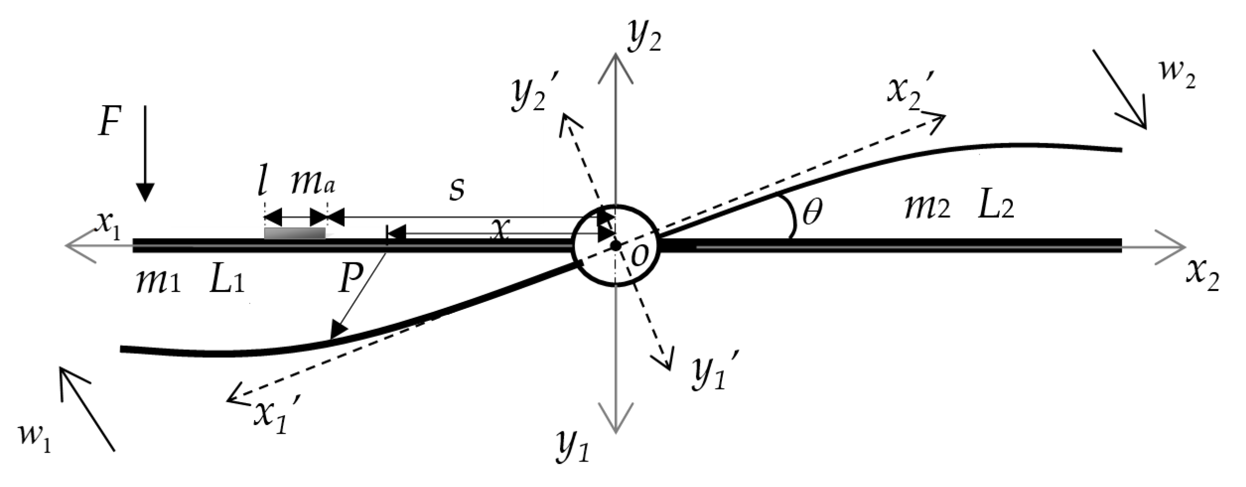
The research object is a central rigid body connected with asymmetric flexible cantilever beams, as shown in
Figure 1. The Cartesian coordinate system is also displayed in
Figure 1, where
o-
x1y1 and
o-
x2y2 are inertial coordinate systems describing the motion of two beams, respectively, and
o-
x1′
y1′and
o-
x2′y2′ are floating coordinate systems after angular displacement of
θ. The bending vibrations of the cantilever beams on both sides of the central rigid body are considered. Both cantilever beams are Euler–Bernoulli beams with lengths
L1 and
L2, and line densities
m1 and
m2. A lumped mass with length
l and line density
ma is attached to one side of the two beams to simulate the disordered local lumped mass on the solar wing. The distance of the lumped mass from the coordinate origin is
s.
The motion of the system shown in
Figure 1 consists of two parts. The first part is the rigid attitude rotation,
θ, driven by the central rigid body together with the two cantilever beams on both sides, and the second part is the bending vibration,
w(
x,
t), of each of the two cantilever beams. Therefore, the system is a rigid-flexible coupled dynamical system. Hamilton’s principle and the assumed mode method can be used to establish the dynamic equation of the system.
To use the assumed mode method, the attitude angle,
θ, of the system and the bending vibration displacements
w1 and
w2 of the beams on both sides are written in the forms of products of mode shape functions and generalized coordinates, and they can be written as follows [
27,
28]:
where
,
and
are the generalized coordinates corresponding to the attitude rotation and bending vibrations of the beams,
is the angular mode constant, and
and
are the mode shape functions of the cantilever beams, which can be expressed as follows:
where
is the
ith characteristic root corresponding to the characteristic equation of a cantilever beam during bending vibration, which is denoted by
,
and
for
.
Let the global modal generalized coordinate vector of the system be as follows:
Then, the three parts of the motion of the system in Equation (1) can be expressed as follows:
in which
Taking the left beam as an example, when deformation occurs, the position vector of any point,
P, on the beam in the coordinate system,
o-
x1y1, can be written as follows:
in which
where
R is the direction cosine matrix of the floating coordinate system relative to that of the inertial coordinate system.
The velocity of point
P in the inertial coordinate system can be expressed as follows:
Similarly, it can be concluded that the velocity, , of the point on the right beam takes the same form as the above formula.
The kinetic energy of the system consists of four components, i.e., the rotational kinetic energy of the central rigid body, the kinetic energies of the two cantilever beams, and the kinetic energy of the lumped mass. The expression for the total kinetic energy of the system is given as follows:
Because the mass of the central rigid body is much larger than that of the flexible beams on both sides, the motions of the flexible attachments create little disturbance to the central rigid body, so it can be considered that the value of
θ is very small. Since only the small linear bending vibrations of the flexible beams are considered, we can let
and
, and ignore the high-order small variables; then, the expression of kinetic energy can be expanded as follows:
where
is the rotational inertia of the center rigid body, and
M is the total mass matrix of the system, which consists of four parts: the mass matrix
M0 corresponding to attitude rotation, the mass matrices
M1 and
M2 relating to the left and right beams, and the lumped mass matrix
Ma. The specific expressions of these mass matrices are written as follows:
where
is the total rotational inertia of the system.
Since the length,
l, of the lumped mass is very small compared to that of the cantilever beam, the change in the stiffness of the cantilever beam caused by the lumped mass is neglected. Consequently, the potential energy of the system consists of three parts: the torsional potential energy of the central rigid body, and the bending deformation energies of the two cantilever beams. The expression for the potential energy of the system is given as follows:
where
is the torsional stiffness of the central rigid body,
and
denote the bending stiffnesses of the left and right beams, and
K is the total stiffness matrix of the system, which consists of three parts: the torsional stiffness matrix
K0 of the central rigid body, and the bending stiffness matrices
K1 and
K2 of the two beams. The specific expressions of these matrices are written as follows:
Since the added lumped mass is relatively light, its energy dissipation is not considered. Whereas the central rigid body is often subjected to a control term with damping characteristics when it rotates, it can be assumed that the energy dissipated by the whole system mainly originates from the central rigid body, i.e.,
where
cθ is the damping coefficient, and
D is the energy dissipation function that represents the work carried out by the damping force during the vibration of the system.
Assuming that an external force,
F, is applied on the left beam at
x0, the virtual work done by the external force
F is
where
Q is the generalized force vector.
Substituting the kinetic energy,
, the potential energy,
, and the virtual work of the external force,
, into Hamilton’s principle [
27,
29,
30],
and introducing the damping term due to the rotation of the central rigid body, the equation of motion of the system can be obtained as follows:
where
is the damping matrix.


