Article

Research on the Aerodynamic Performance and Collaborative Optimization Design of the Full-Scale Compact Inlet Chamber of a Nuclear-Powered Steam Turbine

1
Power Engineering College, Naval University of Engineering, Wuhan 430033, China
2
School of Power and Mechanical Engineering, Wuhan University, Wuhan 430072, China
*
Author to whom correspondence should be addressed.
Machines 2024, 12(4), 262; https://doi.org/10.3390/machines12040262
Submission received: 3 March 2024 / Revised: 1 April 2024 / Accepted: 11 April 2024 / Published: 15 April 2024
(This article belongs to the Section Turbomachinery)

Abstract

:
In nuclear-powered steam turbines, the aerodynamic performance of the inlet chamber tends to be contradictory to the compact design, which makes it difficult to achieve optimal efficiency and power in a nuclear-powered steam turbine. In this study, the quantitative correlation between compact design and aerodynamic performance was investigated to reveal the interaction mechanism between the aerodynamic performance of the inlet chamber of the steam turbine with its compactness. First, the effects of peripheral quantity and arrangement of inlets in the chamber inlet on its aerodynamic performance were studied. The results indicated that the proposed cross configuration exhibited optimized aerodynamic performance in multiple aspects. Then, the effects of two compactness indices (inlet/outlet area ratio and axial spacing at outlet) on the aerodynamic performance of the inlet chamber were investigated. The results indicated that the volume of the inlet chamber was proportional to the inlet/outlet area ratio, and an appropriate design of the inlet chamber can achieve compactness without significantly affecting its aerodynamic performance. In addition, the influencing mechanism of the compact optimization design on the aerodynamic performances of the inlet chamber was revealed. This study provides references for optimization designing an effective and compacted inlet chamber of steam turbines.

1. Introduction

The development of nuclear-powered steam turbines with high power density is of great importance in the economic and military spheres. High-power-density steam turbines need to be equipped with a compact steam inlet mechanism to realize the operation control of the steam turbine. The steam intake mechanism determines the turbine power, efficiency, vibration, operational reliability, and other indicators. Radial intake is one of the features that distinguish nuclear-powered steam turbines from other power plants such as gas turbines. High-power steam turbines are usually designed with multiple cylinders and single shafts, and due to the axial thrust balance, the flow direction in different cylinders differs, so radial intake is a natural choice for steam turbines to reduce shaft length. The radial intake has special requirements for the design of the inlet chamber of steam turbines, i.e., the radial tube bundle intake is induced into an axially uniform axial intake, resulting in a low efficiency of the first (or regulating) stage of the steam turbine [1], and a large part is caused by the non-uniform intake. To improve the efficiency of the first stage, the inlet chamber usually adopts a large-diameter intake channel, and the axial spacing occupied by the inlet chamber is large, leading to a bulky and complex intake mechanism. The spacing of the inlet section of some nuclear steam turbines is larger than 10% of the rotor length (see Figure 1). However, for power steam turbines such as naval vessels, the limited cabin space requires a compacted intake mechanism, which is essential for various reasons, including safety, maneuverability, and operational efficiency, so an effective and compacted inlet chamber is crucial for such power turbines [2,3].
Normally, the compact design of power equipment, including power generation steam turbines [4] and gas turbines [5], can reduce manufacturing costs and increase structural intensity. However, a compact design may increase average velocity and flow loss inside the inlet chamber, cause uneven airflow steering, and increase pressure loss. Specifically, for the inlet chamber of steam turbines, compactness may reduce intake uniformity in the first stage, and non-uniform intake is harmful in at least the following aspects.
(1)
Non-uniform intake imposes bending and radial moments on the rotor, which may result in rotor vibrations [6,7,8] and even faults [9], thus affecting bearing safety [10];
(2)
Non-uniform intake causes mixed loss in the cascade channel [11,12,13,14] or blast loss [15,16], and a mismatch between the chamber outlet airflow angle and the geometric angle of the first stage static cascade causes shock loss [17];
(3)
Non-uniform intake causes an increase in the amplitude of airflow excitation forces on the first-stage dynamic and static lobes [18] and complex excitation force frequencies [5,13,19,20,21,22].
In addition, non-uniform intake may cause cylinder deformation and an uneven belt gap, indirectly increasing air leakage loss [23], and the Thomas/Alford force produced by non-uniform intake may also result in rotor instability [24]. Obviously, the numerical calculation method is an effective method for the thermal and aerodynamic optimization design of thermal equipment [25,26].
Therefore, non-uniform intake not only leads to reduced steam turbine performance but also potentially threatens the intensity and reliability of the steam turbine, and enhancing the compactness of the inlet chamber of the steam turbine is not simply an issue of sacrificing efficiency. In the compact design of the inlet chamber, Siemens designed a high-speed compact steam turbine unit for small nuclear reactors, and its integrated design of steam inlet valves will directly affect its performance [27]. Although this arrangement sacrifices performance slightly, it can shorten the axial spacing of about one static cascade, which is a typical example of sacrificinga small amount of performance for the compactness of the whole machine. Another compactness indicator of the inlet chamber of steam turbines is the inlet/outlet area ratio, which is mainly determined by the number and diameter of the inlets. The single inlet, dual inlet, and quadruple inlet have been used to throttle governing steam turbines with peripheral inlets [23,28]. Quadruple inlets are usually selected for the high- and medium-pressure chambers of high-power steam turbines, while dual inlets are chosen for the low-pressure cylinder design, thereby reducing manufacturing costs and difficulty in installation and maintenance.
To reveal the mutually constraining acting mechanisms between aerodynamic performance and compactness of the steam turbine peripheral inlet chamber, the exchange ratio of compact design and aerodynamic performance is quantitatively given in this paper. First, the influencing mechanism of quantity and arrangement of inlets in the chamber inlet on the inlet chamber’s aerodynamic performance was investigated to find the optimized inlet chamber configuration. Then, the exchange ratio and interaction mechanism between the compact design and the inlet chamber aerodynamic performance were studied by reducing the inlet/outlet area ratio and outlet axial spacing to enhance the inlet chamber compactness. Additionally, the mechanism by which compact design affects the inlet chamber aerodynamic performance is demonstrated, thereby providing references for designing effective and compacted inlet chambers of steam turbines.

2. Numerical Method

2.1. Geometric Model

To explore the effect of the quantity and arrangement of inlets on the performance of the peripheral intake chamber, the six inlet chamber configurations generated by UG NX presented in Figure 2 were investigated, wherein the dual inlet and quadruple inlet have three configurations, respectively. The inlet chamber configurations included dual hedging (2InLine), dual ring (2InCicular), dual parallel (2InParallel), quadruple parallel (4InParalle) and hedging, quadruple ring (2InCircular), and quadruple cross (4InCross), where the quadruple cross configuration has not been reported publicly. Figure 3 illustrates the mid-section of the six inlet chambers, which adopts a compacted symmetric split dual exhaust design with oblique guide channels to reduce the flow loss. The outlet of the inlet chamber is connected with a porous damping ring, which is used to simulate the pressure drop caused by the subsequent cascade.

2.2. Performance Parameters

The aerodynamic performance is characterized by the velocity, pressure drop, outlet angle distribution, and bending moment at the outlet of the intake chamber. The pressure drop can be obtained by
Δ P = P l o c a l P P o r . o u t
where Plocal denotes the local pressure at the outlet of the inlet chamber, and PPor.out denotes the pressure at the porous outlet. The exhaust angle is the angle between the air velocity vector of the outlet of the inlet chamber and the local clockwise tangential direction.
Figure 4 illustrates the bending moment caused by the heterogeneous pressure on the vane wheel disc. The inlet pressure at any point (x,y) on the damping ring is denoted as Pin, the radius to the rotating shaft is denoted as r, and the circumferential angle is denoted as θ. The bending moment TP in the components in the x and y directions can be calculated by
T P i n x = 0 2 π r min r max P i n r 2 sin θ d r d θ T P i n y = 0 2 π r min r max P i n r 2 cos θ d r d θ
Compactness was described by the inlet/outlet area ratio (A) and the axial spacing at the outlet (D) (see Figure 3). A is calculated by
A = A i n A o u t
where Ain and Aout represent the total inlet and outlet areas in the inlet chamber, respectively (see Figure 2a).

2.3. Numerical Model and Boundary Conditions

The numerical model of the inlet chamber is composed of one inlet chamber and two porous damping rings (Figure 5a). The inlet chamber uses an unstructured tetrahedral grid (Figure 5b) generated by Fluent meshing, and the wall surface uses a boundary layer grid (Figure 5c) with adaptive thickness. The damping ring adopts a structured grid. To avoid the flow oscillation caused by inlet pressure, the mass flow rate at the inlet and the static pressure at the outlet are taken as boundary conditions. Based on the experimental comparison in the literature [23], the k-w model is adopted as the turbulence model in this paper. The valve surface adopted ano-slip wall condition.

2.4. Grid Irrelevance Verification and Validation

Before conducting a detailed investigation, grid independence resolution validationwas performed in order to establish a grid-independent solution. Table 1 presents the relative range of outlet velocity for the quadruple crossover configurations with different grid configurations. It can be seen from this table that the relative range of velocity differs by only 2.9% between 11.34 and 22.27 million units. Figure 6 further shows the outlet velocity distribution clouds for different grid configurations. It can be observed that the velocity distribution of the outlet of the inlet chamber achieves grid irrelevance when 11.34 million units are reached. The validity of the numerical method for simulating the inlet chamber flow has been experimentally verified [23,29], and this paper refers to the verified numerical method.
The expansion rate of a Laval nozzle [30] is close to that of an actual steam turbine, so it has been used by many scholars to validate the numerical simulations of the flow in steam turbines. This work simulated the flow in a Laval A nozzle with a throat height of 63 mm and outlet height of 114 mm using the adopted numerical method. Its geometric model is shown in Figure 7a. Steam enters the nozzle with a total pressure of 0.25 bar and total temperature of 354.6 K. Figure 7b compared the pressure distribution on the center line of the numerical simulation and experimental test. As can be seen, the results of the numerical calculation are in good agreement with the experimental data, and the pressure changes near the throat can be well captured.

3. Results and Discussion

3.1. Effects of Quantity and Arrangement of Inlets

The pressure distribution of the outlet of the inlet chamber may affect the stability of the steam turbine operation, so this section first investigates the pressure difference distribution of different configurations of the outlet of the inlet chamber. The pressure difference distribution shown in Figure 8 can reflect the force distribution of the peripheral cascade. Among the three dual inlet configurations, the hedging inlet and parallel inlet both have high-pressure areas in the lower half of the outlet, and the high-pressure areas are highly concentrated. This pressure distribution may impose a bending moment on the rotor, as illustrated in Figure 4, which reflects the bending moment of the rotor due to the uneven air outflow from the inlet chamber. The calculated bending moments for the three configurations are 9.74 kN·m, 6.20 kN·m, and 0.34 kN·m, and the bending moment for the ring intake is an order of magnitude smaller than that of the hedging intake. The pressure range reflects the non-uniform intake’s impact on the amplitude of airflow excitation force, and the pressure ranges of the three dual inlet configurations are 286 kPa, 255 kPa, and 138 kPa, respectively. The pressure range of the dual ring intake is half of that of the hedging intake, and the dual ring intake is better in terms of reducing the bending moment and the airflow excitation force. The pressure distribution of the quadruple inlet is more uniform than that of the dual inlet, and the pressure difference distribution of the cross configuration is the most uniform among the six configurations.
The velocity uniformity of the outlet of the inlet chamber directly affects the efficiency of the first and subsequent stages; meanwhile, mixed loss, airing loss, shock loss, and part of the secondary flow loss are all directly related to the intake rate uniformity of the cascade. The velocity uniformity is reflected in two aspects: velocity value uniformity and angular uniformity. Figure 9 shows the velocity distribution clouds for different configuration outlets of the inlet chamber. It can be seen from this figure that the dual ring inlet configuration in the dual inlet configuration has the smallest velocity maximum and the smallest expected aerodynamic loss. Among the quadruple inlet configurations, the maximum velocities of the parallel and hedging configuration and the cross configuration are similar, while the maximum velocity of the tangential configuration is the largest, and the expected aerodynamic loss is the largest.
Figure 10 illustrates the distribution of different configuration deflection angles, which characterize the degree of airflow deviation from the normal direction. Since the inlet geometry angle of the first-stage static lobe is usually 90°, the larger the deflection angle, the larger the shock and flow loss in the first-stage cascade channel. Among the quadruple inlets, the ring configuration leads to a larger overall flow deflection angle than the cross and parallel configurations due to the formation of a cyclonic flow in the inlet chamber, with a non-zero average deflection angle (see Figure 11). Under the cross configuration and parallel configuration, the deflection angle shows four parallel white bands; the four white bands of the cross configuration appear evenly at 90° apart, and this is because each inlet corresponds to the intake of the 90° arc segment, and the airflow deflection angle at the junction of the arc segment is close to zero, indicating that there is almost no flow or airflow exchange between the arc segments.
For the radial means of pressure difference, velocity, and deflection angle of Figure 8 to Figure 10, the circumferential distribution curves of pressure difference, velocity, and deflection angle of different configurations are obtained and shown in Figure 11, which reflect the aerodynamic performance of different configurations more intuitively. It can be observed from Figure 11 that increasing the number of inlets, i.e., increasing the inlet/outlet area ratio, has the most significant effect on improving aerodynamic performance. Under the same number of inlets and areas, the placement of inlets also significantly affects aerodynamic performance, with dual inlet achieving the best performance for the dual ring inlet and quadruple inlet achieving the best performance for the cross inlet.
To quantify the aerodynamic performance of different inlet chamber configurations, the performance indicators were further parameterized. Table 2 presents the mean, range, and relative range of pressure difference, velocity, and deflection angle of different configurations, and the results are ranked in decreasing order of the relative range. The pressure difference of the parallel configuration with dual inlets has a relative range of 107.3%, which is 8 times higher than that of the cross configuration with quadruple inlets, and the velocity relative range even reaches 46.7 times higher. The average deflection angle of all configurations except the cross configuration is not 0. Although the parallel configuration and hedging configuration have geometric symmetry, the flow field does not have good symmetry. The cross configuration achieves the highest aerodynamic performance in terms of pressure difference and velocity uniformity. Based on the cross configuration, the cost of the compact design was quantitatively analyzed by reducing the inlet area and outlet center distance to improve the compactness of the inlet chamber.

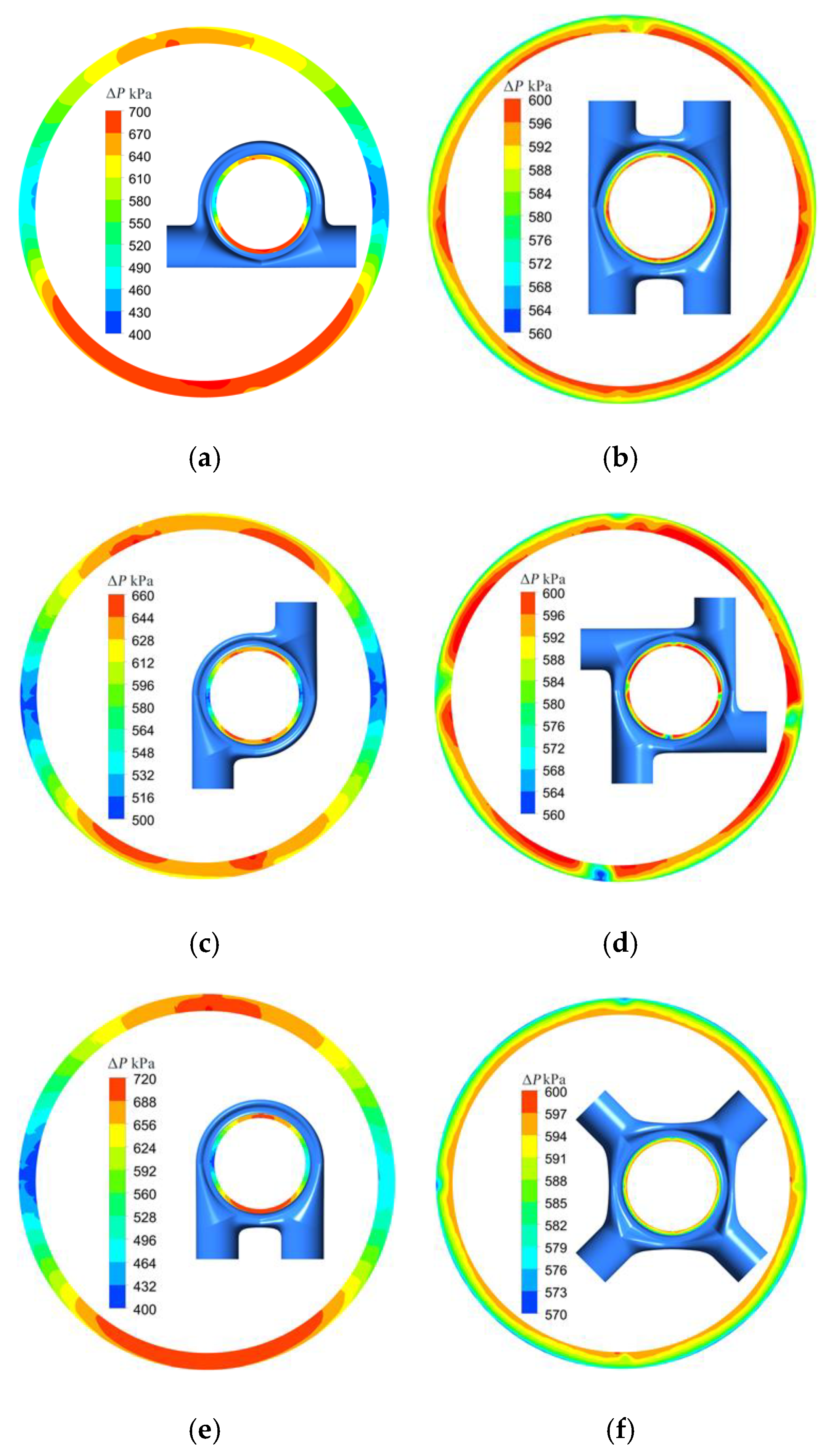
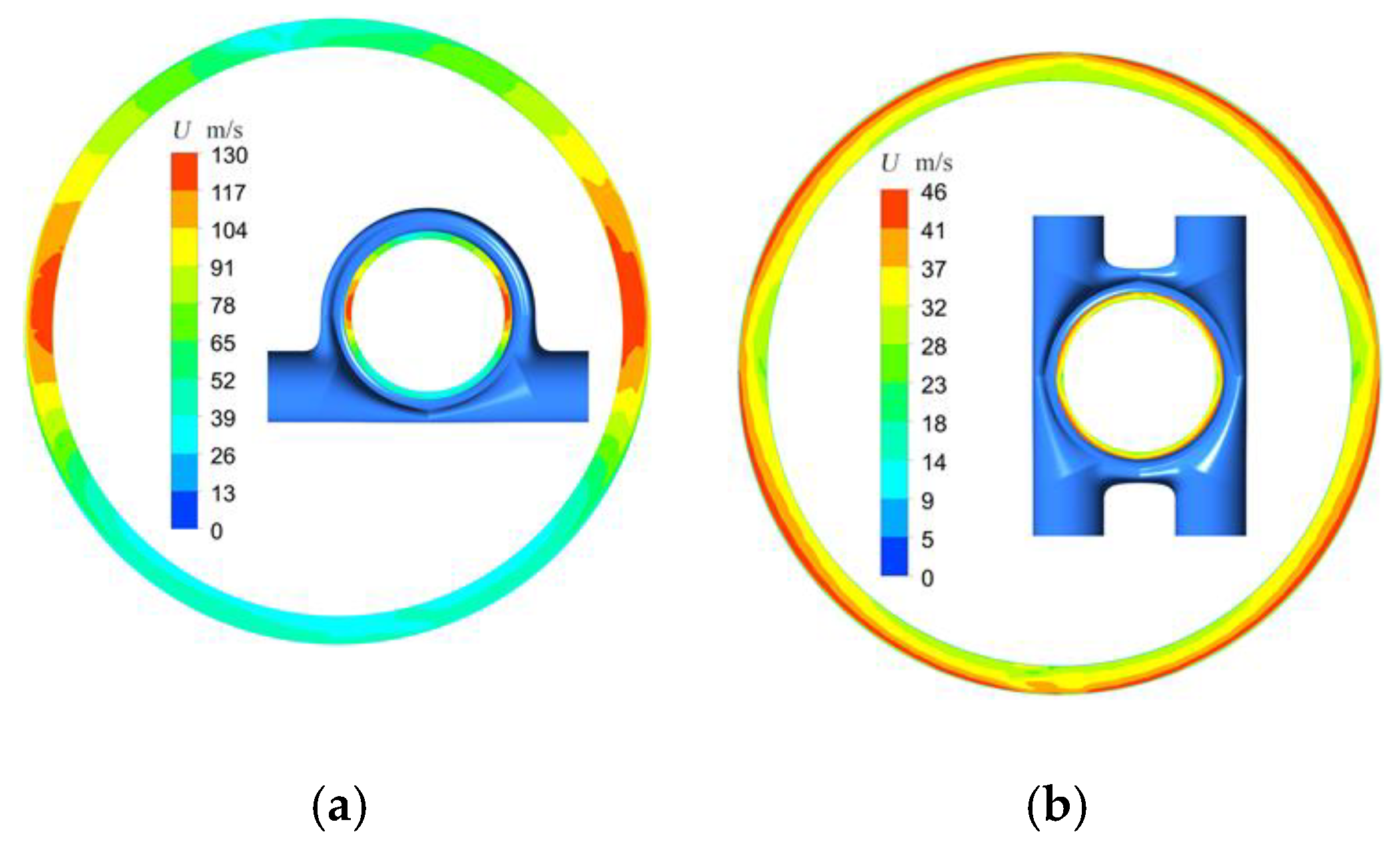
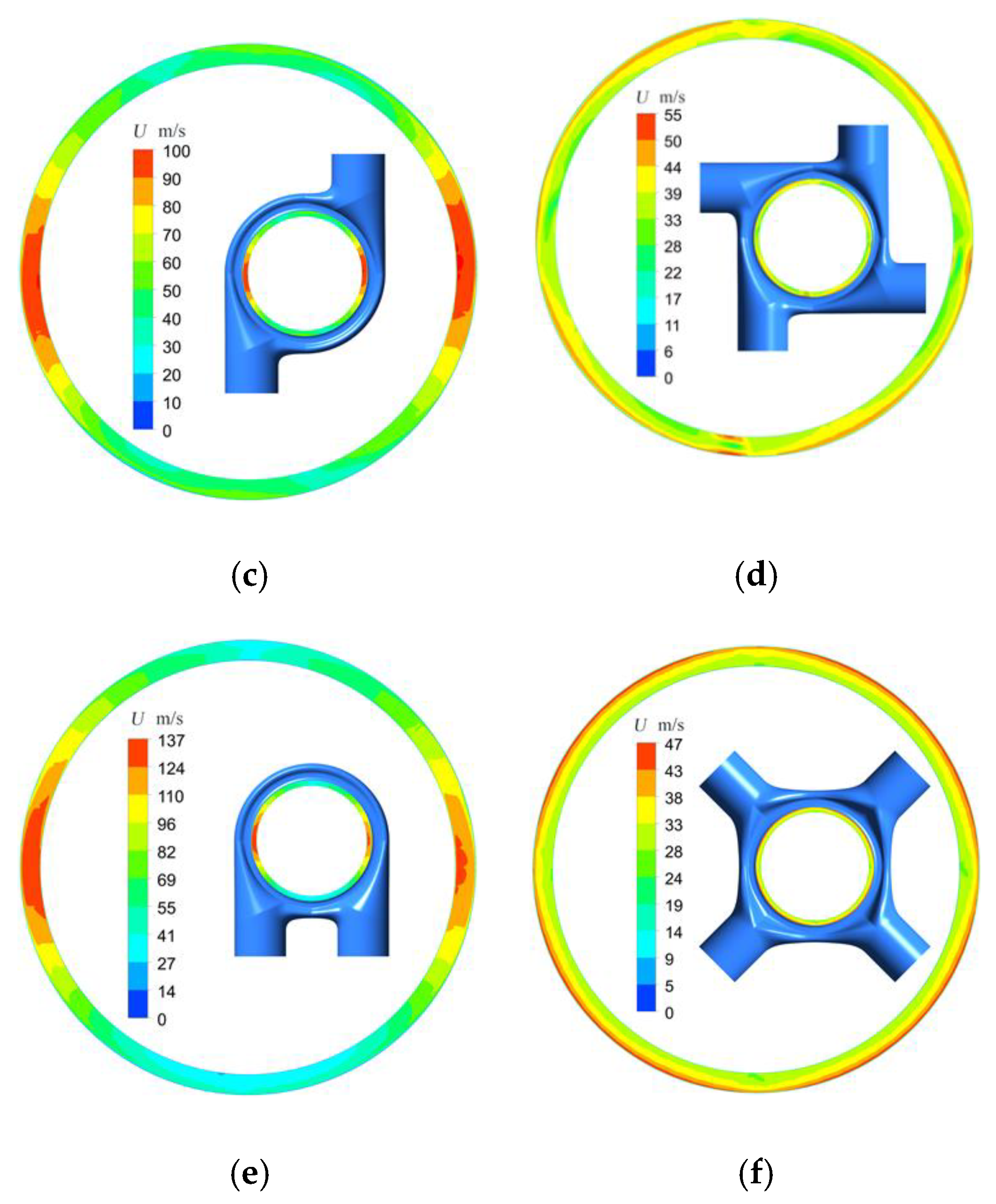
3.2. Effect of Compact Design on Aerodynamic Performance

The cross configuration exhibits excellent aerodynamic performance in several aspects such as pressure difference distribution, bending moment, velocity distribution, and deflection angle distribution, and this section further investigates the effect of compactness on aerodynamic performance under this cross configuration. In this paper, the inlet area of the cross configuration is halved to enhance the compactness of the inlet chamber. Reducing the outlet spacing is another way to improve the overall compactness of a steam turbine. In this paper, the outlet spacing is halved to obtain the cross-section of the inlet chamber, as shown in Figure 12a. The outlet center distance is 120 mm, which is even shorter than the blade height in the first stage, and the inlet chamber has higher axial compactness.
As shown in Figure 13, the inhomogeneity caused by compactness is obvious in the circumferential curves of pressure difference, velocity, and deflection angle, and the variation pattern is almost the same for different curves, but the amplitude of fluctuation in the compacted inlet chamber is greatly increased. The decrease in area ratio leads to a 38.2% decrease in the volume of the inlet chamber, and the decrease in outlet spacing leads to a 7.7% decrease, so the former has a greater impact on the volume of the inlet chamber and therefore on the aerodynamic performance.
Table 3 compares the aerodynamic performance indices for different compacted cross configurations. A 50% reduction in area ratio leads to a 55%, 9.8%, and 21% increase in velocity, pressure difference relative range, and deflection angle range, respectively, and a 50% reduction in outlet spacing leads to a 45%, 0.5%, and 18.6% increase, respectively. The miniaturized cross configuration has slightly lower velocity uniformity than the parallel and hedging configuration, but it has better pressure difference uniformity, and deflection angle uniformity is comparable between them. Meanwhile, the aerodynamic performance of the compacted cross configuration is comparable to that of the parallel configuration, but it is significantly higher than that of the dual inlet configuration with the same area ratio. Thus, a certain aerodynamic performance can be sacrificed for compactness, and a reasonable and efficient inlet chamber can improve both aerodynamic performance and compactness. A smaller inlet diameter can reduce the manufacturing cost of the inlet chamber and channel while improving its rigidity and convenience of installation and maintenance. A smaller outlet spacing can reduce the manufacturing cost of the inlet chamber and rotor while improving its rigidity. Optimizing the inlet chamber and improving aerodynamic performance is significant for improving the performance of the steam turbine, enhancing the compactness of the inlet chamber and the whole steam turbine, and reducing its manufacturing and maintenance costs.
To reveal the mechanism by which compactness affects exhaust uniformity in terms of the flow, the travels of the airflow through the inlet chamber are counted in this section. Figure 14a shows the traces of the airflow from an inlet to the exhaust port under the cross configuration, and it can be seen that the traces are mainly concentrated in the 1/4 arc region of the inlet chamber, and the airflow has very little movement to the adjacent arc. The travel distance distribution can be obtained by counting the travel lengths of the traces in the figure, as shown in Figure 14b. Obviously, the airflow stroke is shorter in the middle, and it increases gradually on both sides and sharply near the edge of the arc, forming dark patches. These patches correspond to the low-velocity region in Figure 9 because a longer stroke leads to a larger flow loss, which is manifested in the low-velocity region of the outlet. There is a strong correlation between trace travel and outlet velocity, and the influence mechanism of the compactness on air outlet uniformity can be analyzed by trace travel.
Figure 14c further presents the longest and shortest traces, and together with Figure 15, which shows the variation of velocity along the traces, the mechanism by which the compact design leads to the expansion of the low-velocity zone of the outlet can be explained. The trajectory and velocity variation of the long-travel mass point indicate that the airflow in the low-speed region undergoes three stages from the inlet to the outlet. Specifically, in the first stage, the airflow mainly moves in the radial direction; in the second stage, it mainly moves in the circumferential direction; in the third stage, it moves in the helical radial direction. Meanwhile, the airflow undergoes two largeangle turns: the first is from radial to circumferential, which is relatively smooth; the second is from circumferential to radial, which is completed by vortices at the corner due to the large turning angle. The main difference between the velocities of different compactness traces in the third stage lies in the fluctuation of circumferential velocity and axial velocity (see Figure 15). Obviously, the larger the amplitude of the fluctuations, the larger the vortex diameter and intensity. The intensity of the vortex depends on two factors: the cut-in velocity, and the rotation space. The maximum cut-in velocities for a small inlet area and a small axial spacing are 24.8 m/s and 24.3 m/s, respectively, which are significantly larger than the comparison benchmark of 16.7 m/s. The inlet velocity for a small inlet area is almost twice as large as the reference, leading to a larger tangential velocity; the small axial spacing results in a smaller cross-sectional area for the circumferential flow, leading to a larger circumferential and tangential velocity. The small outlet spacing has a smaller rotation space, which limits the development of vortices. The overall performance is that the small inlet area vortex is the largest, the short axial spacing is the second largest, and the comparison reference is the smallest. A larger vortex leads to a larger range of low-velocity regions, which reduces exhaust uniformity.
Overall, a compact design leads to larger radial or circumferential flow velocities in the inlet chamber under the same flow rate, making it easier to form large-size and high-intensity vortices when the airflow is diverted, resulting in an uneven exhaust. Therefore, effective and compact inlet chambers should avoid a large angle turning of airflow; also, according to the trajectory of airflow in the low-speed region, the flow guide structure should be reasonably designed to guide the airflow to turn evenly and slowly, e.g., tightening the cross-sectional area at the junction of different curvatures and further increasing the transition angle from the radial to the circumferential direction.

4. Conclusions

In steam turbines, the aerodynamic performance of the inlet chamber tends to be contradictory to a compact design. In this study, the quantitative correlation of compact design with aerodynamic performance was investigated to reveal the interaction mechanism between the aerodynamic performance of the inlet chamber of the steam turbine and its compactness.
First, the effects of peripheral quantity and arrangement of inlets in the chamber inlet on its aerodynamic performance were investigated. The results indicated that each exhaust non-uniformity index of the dual-inlet configuration is an order of magnitude higher than that of the quadruple inlet. Herein, the pressure difference relative range for the dual-inlet parallel configuration is 107.3%, which is 8 times larger than that of the quadruple inlet cross configuration, and the relative range of velocity even reaches 46.7 times larger. The dual ring inlet achieves the best performance under the dual inlet configuration, and the cross inlet achieves the best performance under the quadruple inlet configuration. The cross configuration shows excellent aerodynamic performance in velocity, pressure difference, deflection angle distribution, and bending moment. The velocity relative range is only 13.4%, the average airflow deflection angle is 0°, the deflection angle range is 41.7°, the pressure difference relative range is only 1%, and the bending moment caused by the pressure difference is only 0.24 kN·m.
Based on the optimized inlet chamber configuration, the effects of different compactness indices on the aerodynamic performance of the intake chamber were investigated by reducing the inlet/outlet area ratio and the outlet spacing to improve the compactness. The results indicated that reducing the inlet/outlet area ratio is more effective in reducing the volume of the intake chamber, and it has a greater impact on the aerodynamic performance. The area ratio and outlet spacing were reduced by 50%; the former led to an increase of 55%, 9.8%, and 21% in the velocity, pressure difference relative range, and deflection angle range, respectively, while the latter led to an increase of 45%, 0.5%, and 18.6%, respectively. The aerodynamic performance of the compacted cross configuration remains comparable to that of the parallel and hedging configuration, which demonstrates that a proper intake chamber design can achieve compactness while maintaining aerodynamic performance. In addition, the mechanism by which the compact design affects the aerodynamic performance of the inlet chamber is revealed, and the compact design leads to higher radial or circumferential flow velocities in the inlet chamber under the same flow rate, making large and high-intensity vortices easier to form when the flow is diverted, manifesting as low-velocity areas at the outlet of the inlet chamber, resulting in uneven discharge. Our study sheds light on the intricate dance between compactness and efficiency in nuclear-powered steam turbine inlet chambers. A 50% reduction in area ratio leads to a 55%, 9.8%, and 21% increase in velocity, pressure difference relative range, and deflection angle range, respectively, and a 50% reduction in outlet spacing leads to a 45%, 0.5%, and 18.6% increase, respectively. As engineers strive for innovative designs, understanding these trade-offs becomes paramount. Achieving optimal performance while accommodating space constraints requires thoughtful consideration of aerodynamic parameters.

Author Contributions

Conceptualization, W.J.; methodology, L.Z. and W.J.; software, L.X.; validation, L.Z., W.J. and G.C.; formal analysis, L.Z., W.J. and G.C.; investigation, L.Z., W.J. and G.C.; resources, L.Z., W.J. and L.X.; data curation, L.Z. and W.J.; writing—original draft preparation, L.Z. and W.J.; writing—review and editing, L.Z. and W.J.; visualization, L.Z. and W.J.; supervision, L.Z. and W.J.; project administration, L.Z. and W.J.; funding acquisition, L.Z. and W.J. All authors have read and agreed to the published version of the manuscript.

Funding

This work was supported by National Natural Science Foundation of China [grant numbers 52306046] and Natural Science Foundation of Jiangsu Province [grant numbers BK20230266].

Data Availability Statement

The data used to support the findings of this study are available from the corresponding author upon request.

Conflicts of Interest

The authors declare no conflict of interest.

References

  1. Gan, Y.M.; Huang, C.; Wang, W.L. Flow behavior of laval nozzle sets in steam turbine governing stage at low loads. Therm. Sci. Eng. Prog. 2023, 46, 102209. [Google Scholar] [CrossRef]
  2. Slama, V.; Simurda, D.; Lenhard, R. Pressure Losses Downstream of a Compact Valve in the Inlet Chamber of an Intermediate-Pressure Steam Turbine. Energies 2022, 15, 8753. [Google Scholar] [CrossRef]
  3. Sláma, V.; Šimurda, D.; Mrózek, L.; Tajč, L.; Hála, J.; Radnic, T. Pressure losses and oscillations in a compact valve of a steam turbine. Power Syst. Eng. 2021, 345, 00027. [Google Scholar] [CrossRef]
  4. Damavandi, M.D.; Mousavi, S.M.; Hamed Safikhani, H. Pareto optimal design of swirl cooling chambers with tangential injection using CFD, GMDH-type of ANN and NSGA-II algorithm. Int. J. Therm. Sci. 2017, 122, 102–114. [Google Scholar] [CrossRef]
  5. Simonassi, L.; Zenz, M.; Bruckner, P.; Heitmeir, F.; Marn, A. Aeroelastic and Aerodynamic Investigation of a Low Pressure Turbine Under the Influence of a Circumferential Inlet Distortion. In Proceedings of the ASME Turbo Expo: Power for Land, Sea, and Air, Phoenix, AZ, USA, 17–21 June2019. [Google Scholar]
  6. Zheng, Y.; Jin, X.B.; Yang, H. Effects of Asymmetric Vane Pitch on Reducing Low-Engine-Order Forced Response of a Turbine Stage. Aerospace 2019, 694, 694. [Google Scholar]
  7. Gao, L.; Dai, Y.; Wang, Z.; Xu, Y.; Ma, Q. Rotordynamic Stability Under Partial Admission Conditions in a Large Power Steam Turbine. In Proceedings of the ASME Turbo Expo 2009: Power for Land, Sea and Air, Orlando, FL, USA, 8–12 June 2009. [Google Scholar]
  8. Peng, W.; Ren, X.D.; Li, X.S. Influence of Position of Intake Struts on Unsteady Load and Vibration of First-Stage Rotor. Machines 2022, 10, 1096. [Google Scholar] [CrossRef]
  9. Trebuňa, P.; Pástor, M.; Trebuňa, F.; Šimčák, F. The analysis of failure causes of the rotor shaft of steam turbines. Metalurgija 2017, 56, 233–236. [Google Scholar]
  10. Li, S.S.; Qu, T.Z. Causes and troubleshooting of high bearing bush temperature of a nuclear power steam turbine. J. Phys. Conf. Ser. 2022, 2280, 012035. [Google Scholar] [CrossRef]
  11. Wakeley, G.R.; Potts, I. Origins of Loss Within a Multistage Turbine Environment Under Conditions of Partial Admission. In Proceedings of the ASME International Gas Turbine and Aeroengine Congress and Exhibition, Orlando, FL, USA, 2–5 June 1997. [Google Scholar]
  12. Sitaram, N.; Prasad, B.V.S.S.S.; Yadav Pillala, V.K.; Purushothama, B. Wake Characteristics of a Steam Turbine Rotor Tip Linear Cascade Bladein Subsonic Flow. Indian J. Eng. Mater. Sci. 2022, 29, 137–143. [Google Scholar]
  13. Hushmandi, N.B.; Hu, J.; Fridh, J.; Fransson, T.H. Numerical study of unsteady flow phenomena in a partial admission axial steam turbine. In Proceedings of the Turbo Expo: Power for Land, Sea, and Air, Berlin, Germany, 9–13 June 2008. [Google Scholar]
  14. Pan, Y.; Yuan, Q.; Niu, G.; Gu, J.; Zhu, G. Effect of nozzle box arrangement on the aerodynamic performance of a single stage partial admission turbine. Appl. Therm. Eng. 2019, 159, 113911. [Google Scholar] [CrossRef]
  15. Sakai, N.; Harada, T.; Imai, Y. Numerical study of partial admission stages in steam turbine (Efficiency improvement by optimizing admission arc position). Fluids Therm. Eng. 2006, 49, 212–217. [Google Scholar] [CrossRef]
  16. Guo, Z.; Bai, C.; Han, Y.; Zheng, Q. Numerical Study on the Influence of Exhaust Structure on the Performance of a High Expansion Ratio Turbine. J. Phys. Conf. Ser. 2021, 1881, 042090. [Google Scholar] [CrossRef]
  17. Ahmed, M.; Nagib, E.; Mohey, E. Computational modeling of non-equilibrium condensing steam flows in low-pressure steam turbines. Result Eng. 2020, 5, 100065. [Google Scholar]
  18. Hhshmandi, N.; Bridh, J.; Eransson, T.H. Unsteady Forces of Rotor Blades in Full and Partial Admission Turbines. J. Turbomach. 2011, 133, 2058–2098. [Google Scholar]
  19. Domnick, C.B.; Benra, F.-K.; Dohmen, H.J.; Musch, C. Numerical Investigation on the Time-Variant Flow Field and Dynamic Forces Acting in Steam Turbine Inlet Valves. J. Eng. Gas Turbines Power 2015, 137, 1–11. [Google Scholar] [CrossRef]
  20. Fridh, J.; Laumert, B.T. Forced Response in Axial Turbines Under the Influence of Partial Admission. In Proceedings of the ASME Turbo Expo: Turbine Technical Conference and Exposition, Copenhagen, Denmark, 11–15 June 2012. [Google Scholar]
  21. Clemens, B.D.; Dieter, B. Flow-Induced Steam Valve Vibrations―A Literature Review of Excitation Mechanisms, Preventive Measures, and Design Improvements. J. Eng. Gas Turbines Power 2019, 141, 051009. [Google Scholar]
  22. Gao, K.; Wang, C.; Xie, Y.; Zhang, D. Effects of Inlet Chamber Structure of the Control Stage on the Unsteady Aerodynamic Force. In Proceedings of the ASME Turbo Expo: Power for Land, Sea, and Air, Oslo, Norway, 11–15 June 2018. [Google Scholar]
  23. Hecker, S.; Rohe, A.; Stoff, H. Steam turbine inlet geometry from a structural and fluid dynamics point of view. In Proceedings of the ASME Turbo Expo: Power for Land, Sea, and Air, Copenhagen, Denmark, 11–15 June 2012. [Google Scholar]
  24. Yada, K.; Uchiumi, M.; Funazakik, I. Thomas/Alford Force on a Partial-Admission Turbine for the Rocket Engine Turbopump. J. Fluids Eng. 2018, 141, 011105. [Google Scholar] [CrossRef]
  25. Panda, J.P.; Kumar, B.; Patil, A.K.; Kumar, M.; Kumar, R. Machine learning assisted modeling of thermohydraulic correlations for heat exchangers with twisted tape inserts. Acta Mech. Sin. 2023, 39, 322036. [Google Scholar] [CrossRef]
  26. Panda, J.P.; Kumar, B.; Kumar, M.; Patil, A.K. Influence of twisted tape length on the thermal performance of a heat exchanger tube. Numer. Heat Transf. Part A Appl. 2023, 83, 650–663. [Google Scholar] [CrossRef]
  27. Miroslav, P.; Petrov, J.F.; Goransson, A. High-Speed Steam Turbine Systems for Small-Scale Power Generation Applications. In Proceedings of the 20th International Conference on Nuclear Engineering and the ASME 2012 Power Conference 2012, Anaheim, CA, USA, 30 July–3 August 2012; pp. 651–657. [Google Scholar]
  28. Koprowski, A.; Rzadkowski, R. Computational fluid dynamics analysis of 1 MW steam turbine inlet geometries. Arch. Thermodyn. 2021, 42, 35–55. [Google Scholar]
  29. Kalkkuhl, T.J.; Engelmann, D.; Harbecke, U.; Mailach, R. Numerical analysis of partial admission flow in an industrial steam turbine. In Proceedings of the ASME Turbo Expo: Power for Land, Sea, and Air, Copenhagen, Denmark, 11–15 June 2012. [Google Scholar]
  30. Moore, M.J.; Walters, P.T.; Crane, R.I.; Davidson, B.J. Predicting the fog-drop size in wet-steam turbines. In Proceedings of the IMechE Conference on Heat and Fluid Flow in Steam and Gas Turbine Plant, Wet Steam 4, Coventry, UK, 3–5 April 1973; pp. 101–109. [Google Scholar]
Figure 1. The ratio of inlet section to axial spacing for nuclear turbines.
Machines 12 00262 g001
Figure 2. Different inlet configurations of the inlet chamber: (a) dual hedging; (b) quadruple parallel and hedging; (c) dual ring; (d) quadruple ring; (e) dual parallel; (f) quadruple cross.
Machines 12 00262 g002aMachines 12 00262 g002b
Figure 3. The 2D cross-section of the numerical model.
Machines 12 00262 g003
Figure 4. The rotor bending moment induced by non-uniform intake.
Machines 12 00262 g004
Figure 5. The grid and boundary conditions of the numerical model for the intake chamber: (a) the numerical model; (b) the overall grid; (c) the section grid.
Machines 12 00262 g005
Figure 6. The velocity distribution at the outlet under different grid configurations: (a) 5.53 million units; (b) 11.35 million units; (c) 22.27 million units.
Machines 12 00262 g006
Figure 7. Validation of numerical method: (a) nozzle geometry; (b) comparison of pressure distribution between experimental test [30] and numerical simulation.
Machines 12 00262 g007aMachines 12 00262 g007b
Figure 8. The pressure distribution at the outlet in different chambers: (a) dual hedging; (b) quadruple parallel and hedging; (c) dual ring; (d) quadruple ring; (e) dual parallel; (f) quadruple cross.
Machines 12 00262 g008
Figure 9. The velocity distribution at the outlet in different chambers: (a) dual hedging; (b) quadruple parallel and hedging; (c) dual ring; (d) quadruple ring; (e) dual parallel; (f) quadruple cross.
Machines 12 00262 g009aMachines 12 00262 g009b
Figure 10. The distribution of the velocity deflection angle at the outlet in different chambers: (a) quadruple parallel and hedging; (b) quadruple ring; (c) quadruple cross; (d) dual hedging; (e) dual parallel; (f) dual ring.
Machines 12 00262 g010
Figure 11. The circumstantial distribution of radial-mean outlet differential pressure, velocity, and deflection angle for different chambers: (a) pressure difference; (b) velocity; (c) deflection angle.
Machines 12 00262 g011
Figure 12. The cross-sections with different axial outlet distances: (a) short outlet spacing; (b) comparison to the benchmark.
Machines 12 00262 g012
Figure 13. The circumstantial distribution of radial-mean outlet differential pressure, velocity, and deflection angle for different compactness: (a) pressure difference; (b) velocity; (c) deflection angle.
Machines 12 00262 g013
Figure 14. The trace lines and their stroke distributions in the chamber with different compactness: (a) trace distribution; (b) outlet trace travel distribution; (c) longest and shortest travel traces with different compactness.
Machines 12 00262 g014
Figure 15. The velocity variation along three directions of the longest trace with different compactness configurations.
Machines 12 00262 g015
Table 1. The grid configurations and their corresponding outlet-velocity relative ranges.
Local Grid Size (mm)Surface Grid Size (mm)Maximum Body Unit Size (mm)Boundary Layer Grid Size (mm)Number of Units/10,000(UmaxUmin)/U
Interface 1 and 2Diversion Wall SurfaceMinimumMaximumLayer NumberFirst Layer Width-to-Height Ratio
3103304015105140.130
3103304012105530.145
310330408105640.131
3103304015206090.119
2722030121011350.134
1.551.52023121022270.138
Table 2. Comparison of the aerodynamic performance indices of different chambers.
Inlet Chamber ConfigurationDual ParallelDual HedgingDual RingQuadruple RingQuadruple Parallel and HedgingQuadruple Cross
Aerodynamic
performance
Mean velocity (m/s)71.866.058.838.135.835.4
Range of velocity (m/s)77.167.252.87.56.34.8
Relative range of velocity (%)107.3101.989.919.717.713.4
Mean pressure difference (kPa)614608605593591591
Range of pressure difference (kPa)28625513834116
Relative range of pressure difference (%)46.742.022.85.71.81.0
Bending moment (kN·m)6.209.740.340.550.220.24
Mean deflection angle (°)4.8−2.1−28.9−1.3−19.90.0
Range of deflection angle (°)155.4153.4118.055.649.541.7
Table 3. The aerodynamic performance and compactness indices of different configurations.
Cases4InCross_Base4InCross_Small4InCross_Short
compactness indicesarea ratio1.480.74−50%1.48
outlet center distance (mm)240240 120.0−50%
aerodynamic performance indicesMean velocity (m/s)35.437.1 36.3
range of velocity (m/s)4.767.71 7.07
Relative range of velocity (%)13.420.855%19.545%
Mean pressure difference (kPa)591592 591.0
Range of pressure difference (kPa)5.786.30 5.80
Relative range of pressure difference (%)0.9791.0669.80%0.9840.50%
Mean deflection angle (°)0.03−0.19 −0.16
Range of deflection angle (°)41.759.621%49.518.60%
Disclaimer/Publisher’s Note: The statements, opinions and data contained in all publications are solely those of the individual author(s) and contributor(s) and not of MDPI and/or the editor(s). MDPI and/or the editor(s) disclaim responsibility for any injury to people or property resulting from any ideas, methods, instructions or products referred to in the content.

