1. Introduction
Squeeze film damper (SFD) research and applications have advanced quickly in recent years. SFDs are widely used in the fields of aerodynamics and vibration control of some turbomachinery because of their easy manufacturing process, simple structure, and exceptional vibration damping effect [
1,
2]. SFD is a useful tool for increasing the stability of rotor bearing systems because of their well-thought-out design.
The oil chamber is divided into several oil chambers by the tabs of the elastic ring, and the inner and outer oil membranes are connected through oil seepage holes on the elastic ring. In order to prevent a large amount of oil from seeping out of the end face, there is an oil seal ring on the end face of the damper. SFD generates damping effects through the compression of the inner and outer rings. However, the traditional type of SFD has nonlinear coefficient of dynamic characteristics [
3,
4]. Wang et al. [
5] developed a set-mass dynamic model of aero-engine high pressure rotor system and introduced the nonlinear stiffness and damping equations of the SFD into the above model. The results show that at high speeds, the rotor system will produce complex vibration or bistable vibration due to the nonlinear effect of the squeezed oil film damper. Inayat-Hussain et al. [
6] investigated the unbalanced response of a rigid rotor with SFD and revealed the chaotic state of motion of the rotor system with and without a centering spring. Zhou et al. [
7] investigated the floating ring SFD with a single oil film as well as another with a double oil film. It was discovered that in terms of preventing double stability, asynchrony, and abrupt unbalanced response in transient amplitude, this SFD performs better than the traditional SFD. Tyler et al. [
8] proposed a segmented SFD in 1982; due to its segmented oil film structure, the lubricant has no annular flow, and the nonlinearity of the oil film force has been improved to a large extent. The continuous optimization of the bearing structure of the SR is one of the best ways to improve the nonlinear problem of the coefficient of dynamic characteristics. Combining the aforementioned concepts, the integral squeeze film damper (ISFD) structure emerged in the early 1990s. This damper significantly improves the rotor system’s vibration damping capacity while also making up for the traditional SFD’s nonlinearity of oil film force [
9,
10,
11,
12].
As the main dynamic characteristic coefficients of the ISFD, the stiffness coefficient and damping coefficient largely determine the inhibition effect of the ISFD on rotor vibration [
13,
14]. Poor vibration damping might result from an ISFD damping coefficient that is either too large or too little. When ISFD is operating, it is exposed to both static and dynamic journal stresses. If the damper’s stiffness coefficient is too little, this will cause the journal to be highly eccentric, and if it is too large, this will restrict the journal’s mobility. Therefore, it is particularly important to analyze and identify the coefficients of the dynamics of the ISFD to optimize the design of a suitable ISFD for rotor systems in engineering applications.
The investigation of ISFD dynamics can be started by solving for turbulence, which is highly uncertain. Although the use of computationally intensive methods such as Direct Numerical Simulation (DNS) and Large Eddy Simulation (LES) can provide a high degree of accuracy for solving turbulence, they are too expensive for practical applications so the Reynolds Averaging method was proposed for solving turbulence, hence, the turbulence model. Despite its widespread use, turbulence modeling has inherent structural deficiencies that prevent it from replicating the underlying turbulence process. Due to the simplification of the model, the turbulence model can only represent certain features of turbulence with limited fidelity [
15,
16,
17]. Zhao et al. [
18] analyzed the damping coefficients of the SFD based on the assumption of a full-film short bearing. Zhang et al. [
19] proposed a new deep learning-based information fusion method for the identification of oil film dynamics coefficients in the SFD. A complex vector description of the motions and forces, along with a frequency-domain analysis with a two-sided spectrum, were used by Lee et al. [
20] to propose a method for calculating the damping coefficients of an intershaft SFD. The proposed method’s validity was confirmed by comparing the damping coefficients obtained from CFD analysis of the original intershaft SFD model and its equivalent SFD model. Dong et al. [
21] solved the equivalent stiffness coefficients and equivalent damping coefficients of ISFD based on finite element method and CFD analysis, and San Andrés et al. [
22] obtained the stiffness coefficients and damping coefficients of the squeeze oil-film damper through the experimental study of bi-directional excitation. Zhang et al. [
23] established the finite element model of the integral squeeze oil-film bearing damper (ISFBD) and carried out the analysis of the stiffness characteristics and experimental validation study.
In order to explore the dynamic characteristics of ISFD and reveal the flow characteristics of the oil film, this paper will establish the solid and fluid models of ISFD and list the fluid equations, respectively. It will also perform a numerical analysis of the dynamic characteristics of ISFD, mechanical property analysis, and CFD analysis, confirming that the ISFD’s structure makes sense and investigating the flow characteristics of the ISFD’s oil film region. Finally, the results of numerical analysis will be used to identify the stiffness and damping coefficients of ISFD.
In order to conduct an experimental study on the dynamic characteristics of ISFD, a bi-directional excitation test rig is set up. The formulae for calculating ISFD’s stiffness and damping coefficients are listed, and the stiffness and damping coefficients of ISFD are identified using the mechanical impedance method. Lastly, to verify the accuracy of the results, a comparison is made between the experimental and numerical analytical values of ISFD’s stiffness and damping coefficients.
2. Materials and Methods
2.1. Introduction of ISFD
An ISFD consists of five parts: inner ring, outer ring, S-type elastomer, squeeze oil film area, and oil inlet hole. Generally, the ISFD is installed between bearing housing and bearing, often using interference fit or transition fit. As a result, while the ISFD is operating, the outer ring remains stationary. The vibration energy is transmitted to the inner ring through the bearing, which causes the inner ring to vortex, squeezing the lubricant in the oil film area, producing a squeezing oil film effect so that the vibration energy can be dissipated. On the inner ring, four pairs of S-type elastomers are dispersed symmetrically and equally.
The lubricant flows into the squeeze oil film area from the inlet holes and flows out from the end faces. Since the ISFD’s oil film is divided into four sections and does not flow circumferentially, it performs more linearly than the traditional SFD. The schematic structure of ISFD is shown in
Figure 1.
The stiffness of the ISFD is mainly determined by the structural parameters of the S-type elastomer, while the damping of the ISFD is determined by the oil film force generated in the squeeze oil film region. According to this dynamic characteristic, the ISFD is simplified into a dynamic model with only two degrees of freedom. The main stiffness and main damping of the ISFD in the “X” and “Y” directions are simplified as “
kXX”, “
cXX”, and “
kYY”, “
cYY”, respectively, and the cross stiffness and cross damping of the ISFD in the “X” and “Y” directions are simplified as “
kXY”, “
kYX”, “
cXY” and “
cYX”. Among them, according to the damping mechanism and structural characteristics of ISFD, the simplified dynamic model diagram of ISFD is obtained after simplification and equivalence, as shown in
Figure 2.
2.2. Modeling of ISFD
In order to investigate the dynamic characteristics of ISFD and carry out the mechanical property analysis and CFD analysis of ISFD, it is necessary to establish the solid structure model and fluid model of ISFD according to the structural parameters of ISFD as shown in
Figure 3.
As shown in
Figure 3, the squeeze oil film area of ISFD can be divided into long-squeeze oil film area, short squeeze oil film area, and S-type squeeze oil film area. The flow situation of the oil film area of ISFD is as follows: (1) the lubricant is injected into the squeeze oil film area through the inlet hole; (2) the lubricant flows through the long-squeeze oil film area, the S-type squeeze oil film area, and the short squeeze oil film area; and (3) the lubricant is finally flowed out by the outlet end face. The inner wall of the oil film is in contact with the outside of the inner ring of the ISFD, and the outer wall of the oil film is in contact with the inside of the outer ring of the ISFD. The motion state of the inner wall of the oil film is consistent with that of the inner ring of the ISFD, and the motion state of the outer wall of the oil film is consistent with that of the outer ring of the ISFD.
Before establishing the hydrodynamic equations of ISFD, the following assumptions need to be made: (a) incompressible Newtonian fluid, viscous force is much larger than inertia force; (b) the lubricant is incompressible and thermostatic in the flow process; (c) laminar flow; (d) no slippage at the surface; (e) no external force; and (f) no inertia effect. According to the structural characteristics of ISFD, the Reynolds-like equation of ISFD at the region of squeeze oil film can be listed as follows:
where “
h” is the oil film thickness, “
P” is the pressure of the oil film, “
” and “
” are the density and the dynamic viscosity of the lubricant, respectively, and “
t” is the time.
From Equation (1), we can get the dynamic pressure field generated in the region of extruded oil film when ISFD does vortex motion, and the oil film force generated in the region of extruded oil film can be obtained by integration as follows:
where “
” and “
” are the oil film component forces of ISFD in “
x” and “
z” directions, “
L” is the journal length of ISFD, and “
” represents the ith extruded oil film region of the ISFD. Since there are four oil film regions in ISFD, the value range of “
” is (1, 2, 3, 4), and (
) are the upper and lower limits of integration of the ith squeeze oil film region.
2.3. Bi-Directional Excitation Test Rig
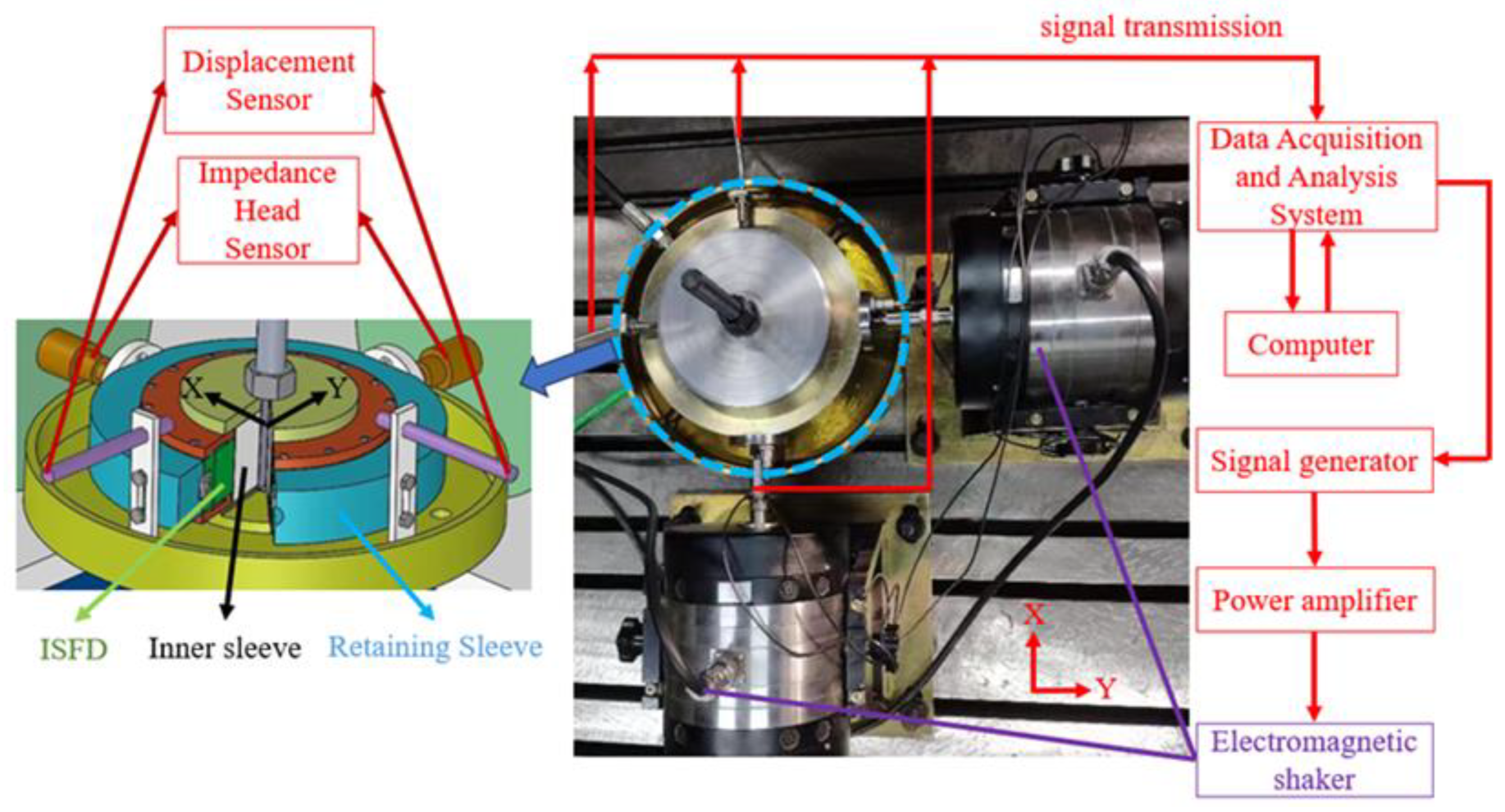
In order to investigate the dynamics of ISFD and carry out the experimental study on the dynamics of ISFD under two-way incentive effect, a bi-directional excitation test rig is built as shown in
Figure 4. The test rig consists of two parts: the bi-directional excitation device and the data acquisition and control system. The data acquisition and control system include a shaker, displacement sensor, impedance head sensor, computer, data collector, signal generator, and power amplifier. The data acquisition and control system can provide bi-directional excitation conditions for the main body of the test rig. At the same time, the system can collect the relevant data such as excitation force and vibration, which are used to calculate the dynamic characteristic coefficients of ISFD.
The specific experimental process is as follows: In order for the stationary sleeve and the ISFD to perform vortex motion together, the computer operates the data collector. The signal generator produces sinusoidal signals, which are then amplified by the power amplifier and used to drive the “X” and “Y” direction shaker. At the same time, the impedance head sensor and displacement sensor measure the excitation force, acceleration, and displacement of the ISFD, respectively. The data collector records, saves, and analyzes the measured data. From the measured data, the stiffness coefficient and damping coefficient of the ISFD can be calculated, which is the required solution for the experiment.
In order to calculate the dynamic coefficients of ISFD, it is necessary to analyze the motion of ISFD under the action of two-way incentive effect. The inner ring of ISFD is fixed and immobile, and the outer ring, together with the fixed sleeve, makes vortex motion. The outer ring of ISFD is subjected to a reaction force formed by the excitation force and the ISFD, which can be expressed as follows:
where “
Cxx”, “
Cyy”, “
Kxx”, and “
Kyy” denote the principal damping and principal stiffness of the ISFD in the “
x” and “
y” directions, which are the quantities required to be solved in the experiment. “
x”, “
y” are the displacements of the outer ring of the ISFD, measured by the displacement sensor.
Then, the equations of motion can be listed based on the forces on the outer ring of the ISFD:
Since the data measured in all the experiments are in the time domain and the motion data of the ISFD in the frequency domain are required in the calculation of the ISFD damping and stiffness coefficients, a single discrete Fourier transform is applied to each parameter.
Where the discrete Fourier Transform of the excitation force is expressed as follows:
The discrete Fourier transform of the acceleration is expressed as follows:
The discrete Fourier transform of the velocity is expressed as follows:
The discrete Fourier transform of the displacement is expressed as follows:
Let an impedance function “
H” be expressed as follows:
In the impedance function, (, ) are the oil film stiffness coefficients and structural stiffness coefficients of the ISFD, respectively, and (, ) are the oil film damping coefficients and structural damping coefficients of the ISFD, respectively. (The subscripts “” and “” denote the “” and “” directions).
Then, Equation (4) can be written as follows:
where
MD = 11.9 kg in Equation (10), two equations can be listed and four impedance coefficients cannot be solved, so two experiments will be done as a group to calculate the four impedance coefficients in the equations. Ten groups of experiments are done consecutively to take the average value to get the stiffness coefficient and damping coefficient of the ISFD.
3. Results
3.1. Mechanical Properties Analysis by ISFD
In order to explore the mechanical properties of ISFD, the static analysis of ISFD is carried out. In engineering applications, usually the outer ring of the ISFD is fixed with the bearing housing, which is a fixed constraint, and the inner ring of the ISFD does precession motion. From this, the constraints of ISFD during mechanical analysis can be determined, as shown in
Figure 5.
The static analysis of the ISFD was carried out; a load of 500 N was applied to the face of the outer ring of the ISFD, a fixed load was applied to the inner ring of the ISFD, and 304 stainless steel was selected as the material. The modulus of elasticity of 304 stainless steel is 1.93 × 10
6 Pa, yield strength is 2.05 × 10
8 Pa, and Poisson’s ratio is 0.31, and it has the advantages of corrosion resistance, oxidation resistance, lead-free, non-rusting, non-oil-contaminated, easy to clean, easy to maintain, and so on. The displacement cloud and stress cloud of ISFD were obtained through analysis as shown in
Figure 6 and
Figure 7.
From
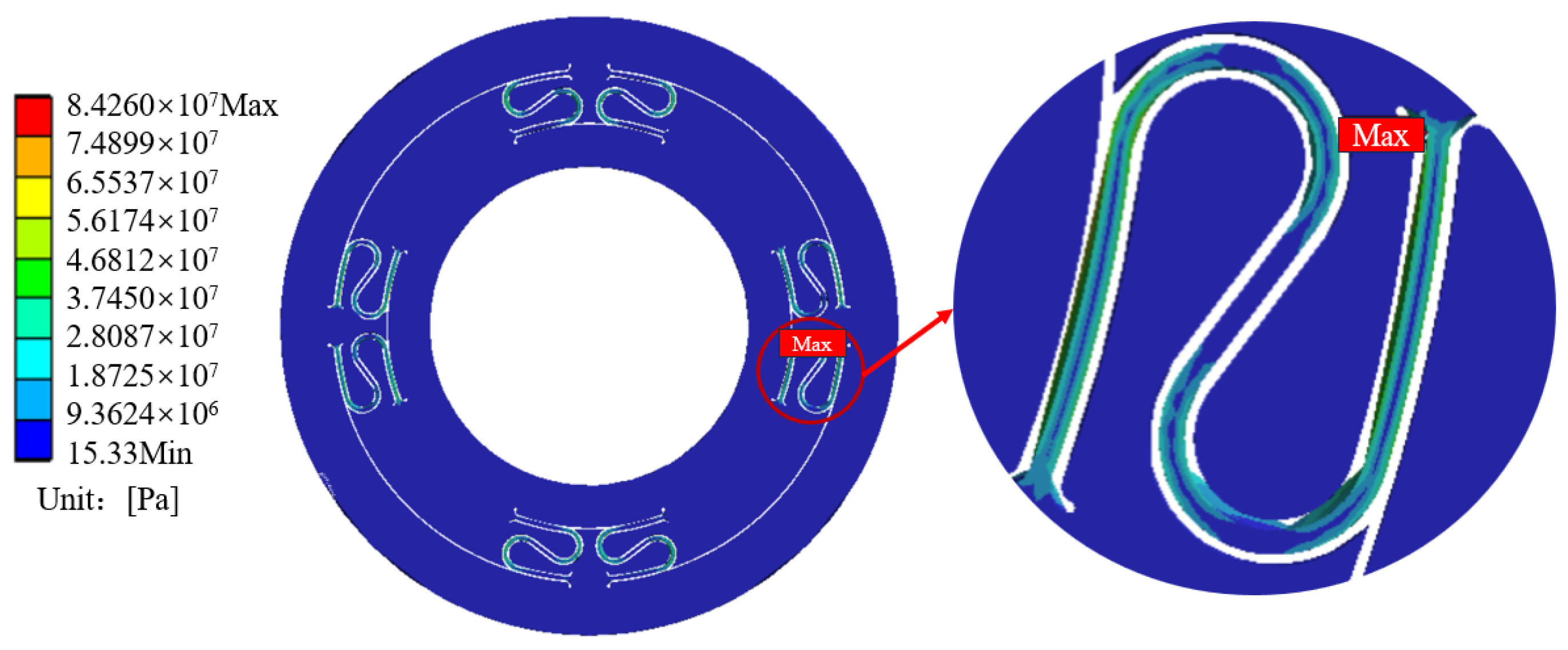
Figure 6, it can be seen that the deformation of the S-type elastomer is uniform and continuous, and the inner and outer rings are not significantly deformed. The deformation that occurs in S-type elastomer is elastic and acts like a spring. From
Figure 7, it can be seen that the structure of ISFD is reasonably designed, and there is no stress concentration phenomenon. The maximum stress of ISFD occurs at the connection between S-type elastomer and the outer ring, and the maximum stress is 8.426 × 10
7 pa. The yield limit of the simulation-selected material, 304 stainless steel, is [
] = 2.05 × 10
8 Pa. The formula for the permissible stress is as follows:
The safety coefficient = 1.5 is chosen, and calculation yields the allowable stress as [] = 1.3667 × 10⁸ Pa according to Equation (11). The maximum stress of ISFD is less than the permissible stress ([] = 1.3667 × 10⁸ Pa), which satisfies the requirements of the strength design and guarantees that the material will not be damaged due to excessive stress.
3.2. CFD Analysis of ISFD
In order to investigate the oil film pressure distribution and flow field characteristics of ISFD, the fluid model of ISFD is used as the research object to carry out the CFD analysis of ISFD. Before the analysis, the dynamic mesh and the main working condition parameters need to be determined.
The inner wall of the oil film is in the same motion state as the inner ring of the ISFD, and the outer wall of the oil film is in the same motion state as the outer ring of the ISFD. It is important to build up a dynamic mesh on the inner wall of the oil film and a static mesh on the outer wall of the oil film because the inner ring of ISFD does whirling motion, resulting in a trajectory that is often circular or elliptical. Mesh-independent analysis has been performed on the model before analysis. Mesh size needs to be kept below 0.25 mm and the mesh is encrypted in areas of small volume. The number of the model meshes for this analysis is 1.87 × 10
7, and the number of nodes is 3.59 × 10
6. The eddy amplitude and eddy frequency are set in the customized UDF file.
Table 1 shows the main working condition parameters of ISFD.
The whirling motion equation of ISFD oil film inner wall is set in the UDF file as follows:
where “
dx” and “
dz” are the displacements of the ISFD inner ring in the “X” and “Z” directions, respectively. The “
A” is the eddy amplitude of the ISFD inner ring. Derivation of Equations (13) and (14) yields “
vx” and “
vz”:
After CFD analysis the fluid pressure distribution cloud and velocity vector maps at different moments of the ISFD are obtained, as shown in
Figure 8 and
Figure 9.
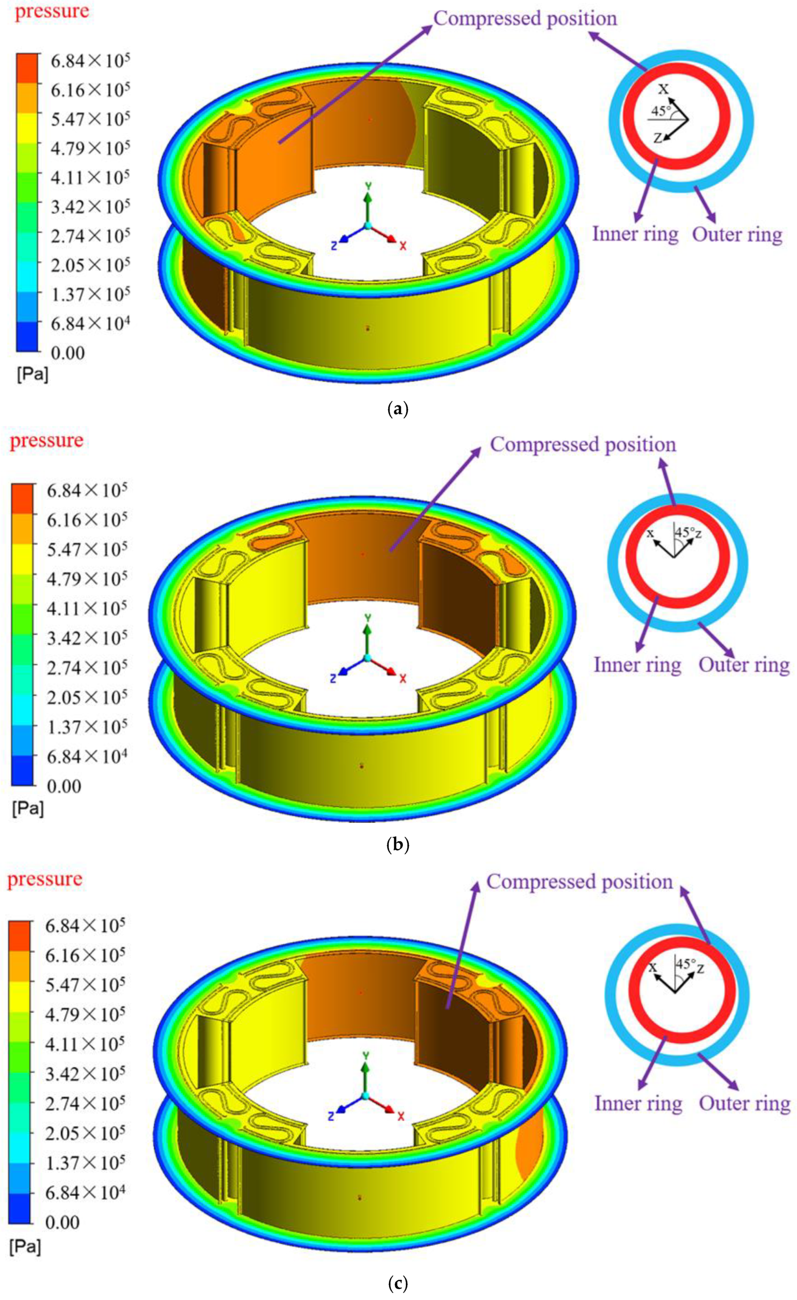
The location of the squeezed ISFD oil film at different moments is indicated in
Figure 8: (a) at T = 0.0150 s, the squeezed position in the ISFD is located near the short-squeezed oil film region at the upper left corner; (b) at T = 0.0200 s, the squeezed position is located near the long-squeezed oil film region at the upper right corner; and (c) at T = 0.0250 s, the squeezed position is located near the short-squeezed oil film region at the upper right corner. A 1/4-cycle vortex motion is completed, and at the moment of T = 0.0250 s, the ISFD enters the next 1/4-cycle whirling motion.
It can be seen that the magnitude of the fluid pressure in the region of the squeeze oil film in the ISFD at different moments varies with the position of the movement of the inner ring of the ISFD, and the fluid pressure in the squeezed area is significantly higher than that in the unsqueezed area. In addition, the lubricant is injected through the inlet hole and enters the long-squeezed oil film area. Due to the relatively large space of the long-squeezed oil film area, the fluid pressure becomes smaller after the lubricant enters, so the pressure at the oil inlet hole is significantly higher than the pressure at the long-squeezed oil film area.
Figure 8 shows that: (1) T = 0.0150 s moment, for example, in this moment the pressure change in different positions is more uniform; (2) using the long oil film location in the fourth quadrant of the “x-z” coordinate system as an example, this region experiences relatively uniform pressure changes at various times. If the position is not changed between the squeezed and non-squeezed zones, it will not experience abrupt pressure changes or cavitation phenomena over time.
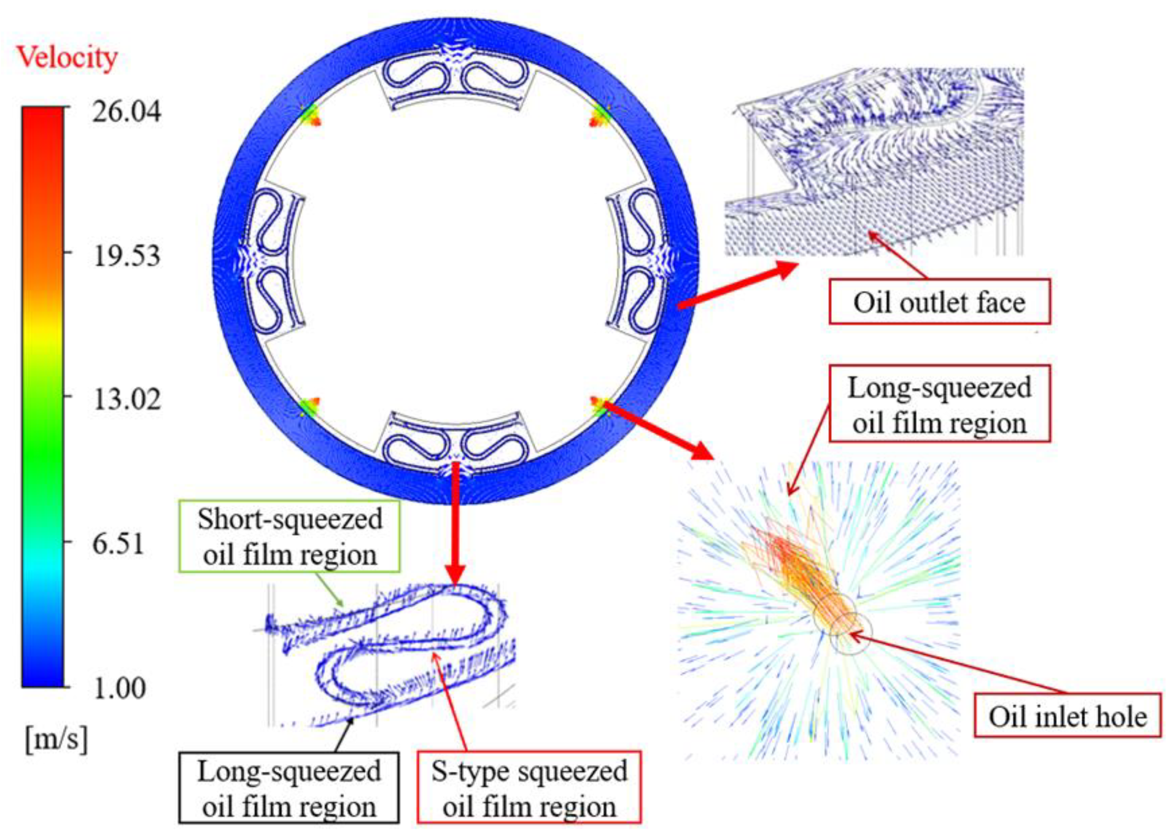
The velocity vector diagram of the ISFD flow field at the moment T = 0.0225 s is shown in
Figure 9. The left part of
Figure 9 shows that the lubricant flows from the inlet hole into the long-squeezed oil film area at a high rate. Since the area of the long-squeezed film zone is much larger than the cross-sectional area of the inlet hole, the flow rate of the lubricant decreases significantly after flowing into the long-squeezed film zone. The lower part of
Figure 9 shows the flow of lubricant into the S-type squeeze film area and the short-squeezed film area. The right side of
Figure 9 shows the lubricant flowing out of the end gap in the long-squeezed film area, the S-type squeeze film area and the short-squeezed film area.
3.3. Stiffness Properties of ISFD
In order to investigate the stiffness characteristics of the ISFD and the influence of load on the stiffness coefficient of the ISFD, the mechanical analysis and experimental study of the ISFD are carried out under different loading conditions.
Based on the analysis method in
Section 3.1, the mechanical characterization of the ISFD is carried out to obtain the displacements generated by the outer ring of the ISFD under different loading conditions. In order to verify the validity of the numerical analysis results, the experimental validation study of the ISFD stiffness characteristics is carried out in the bi-directional excitation test rig to investigate the change rule of the displacement of the outer ring of the ISFD with the load force. The displacement will be produced when the shaker provides load to the outer ring of ISFD since the inner ring of ISFD is fixed. As a result, throughout the experiment, the shaker can apply various load forces to the ISFD outer ring in order to detect the relative displacement of the outer and inner rings. The loads applied to the outer ring of ISFD during the analysis and experiment are all from 20 N to 300 N. Based on the data obtained from the numerical analysis and experimental study, the variation in ISFD displacement with load can be plotted as shown in
Figure 10.
From
Figure 10, it can be seen that the displacement of ISFD increases with increasing load and is linearly correlated. This demonstrates that, under a variety of load circumstances, the ISFD has strong linear stiffness characteristics.
The stiffness coefficient of ISFD is calculated as follows:
where “
k” is the stiffness coefficient of the ISFD, “
n” is the number of loads, “
Fi” is the radial load, and “
Di” is the displacement of the ISFD under the load “
Fi”.
Substituting the data in
Figure 10 into Equation (17), the numerical analysis value of the ISFD stiffness coefficient is calculated to be 1.99 × 10
6 N/m and the experimental value is 2.01 × 10
6 N/m.
3.4. Damping Characteristics of ISFD
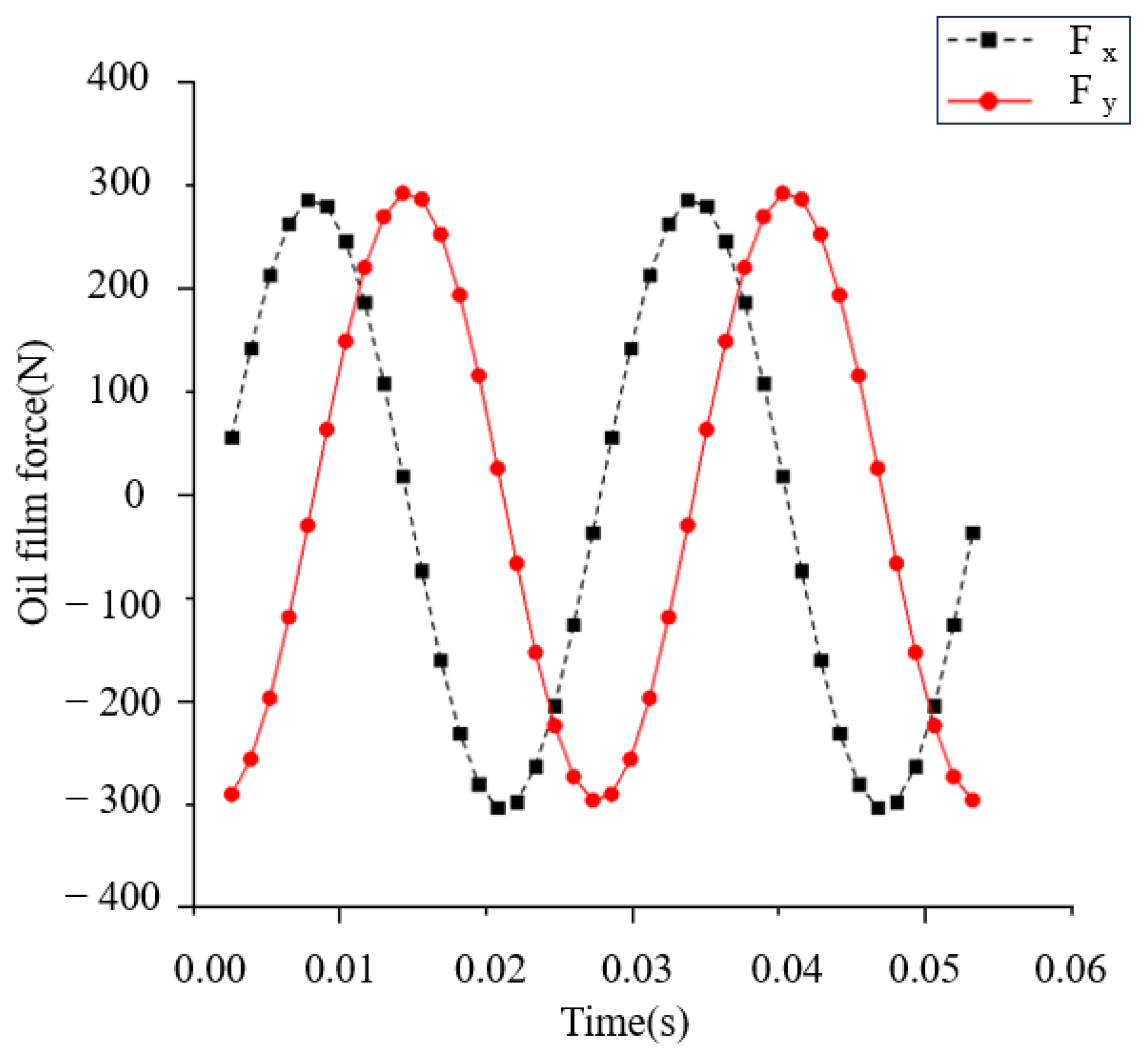
In order to explore the damping characteristics of the ISFD, investigate the law of oil film force with time, and identify the damping coefficient of the ISFD, numerical analysis and experimental study of the ISFD are carried out.
According to the results of the pressure cloud analysis obtained in
Section 3.2, the oil film pressure obtained from the analysis is integrated, and the curve of the oil film force with time can be plotted, as shown in
Figure 11.
By definition, the damping coefficient is as follows:
where “
e” is the eccentricity of the journal, and “
” is the journal feed angular velocity. The numerical analysis value of ISFD damping coefficient can be calculated as 2.31 × 10
5 (N∙s)/m by substituting the oil film force in
Figure 11 into Equation (17).
On the bi-directional excitation test rig in
Section 2.3, a total of 20 sets of data are measured for four parameters (namely, excitation force, acceleration, velocity, and displacement), under the condition that the excitation frequency of the shaker is 20 Hz and the amplitude is 4 μm. The peak values of the measured parameters are shown in
Table 2, and the time-domain plots of the measured parameters are shown in
Figure 12.
According to the experimentally measured data, insert every two experimental data as a group into Equation (10) and solve the four impedance coefficients. The experimental value of the ISFD damping coefficient is calculated to be 2.12 × 10⁵ (N∙s)/m.
4. Conclusions
In order to analyze and study the dynamic characteristics of ISFD, solid and fluid analytical models of ISFD were established, mechanical property analysis and CFD analysis were carried out, and a two-way excitation test rig was constructed. The stiffness coefficients and damping coefficients of ISFD were determined by numerical analysis and experimental methods, and the following conclusions were drawn:
(1) The deformation of the S-type elastomer, which provides structural stiffness, is uniform and continuous. There is no discernible deformation in the inner and outer rings of the ISFD or stress concentration phenomenon according to the displacement and stress clouds of the ISFD that are obtained from the static analysis. The stiffness of ISFD can be seen to vary linearly in the two plots of displacement versus load obtained by combining the static analysis and experimental study, respectively. The numerical analysis values of ISFD stiffness coefficients are closer to the experimental values, which verifies the accuracy of the numerical analysis conclusions.
(2) The oil pressure distribution graph of ISFD at various times, which is produced using CFD analysis, demonstrates that each type of oil film’s pressure varies consistently over time and does not cause abrupt variations or the cavitation phenomenon. Furthermore, the graph of oil film force with time produced by numerical integration shows that ISFD has good damping characteristics. The numerical analysis value of ISFD damping coefficient is also more similar to the value of the damping coefficient obtained by the experimental method, confirming the accuracy of the numerical analysis results.


