Article

Investigation of Torque and Reduction of Torque Ripples through Assisted-Poles in Low-Speed, High-Torque Density Spoke-Type PMSMs

1
College of Electrical Engineering, Zhejiang University, Hangzhou 310027, China
2
Zhejiang Provincial Key Laboratory of Electrical Machine Systems, Hangzhou 310027, China
*
Author to whom correspondence should be addressed.
Machines 2024, 12(5), 327; https://doi.org/10.3390/machines12050327
Submission received: 3 April 2024 / Revised: 8 May 2024 / Accepted: 8 May 2024 / Published: 10 May 2024

Abstract

:
In this article, rotor designs utilizing assisted-poles are investigated for a high-torque density spoke-type permanent magnet synchronous machine (PMSM) with fractional slot concentrated winding (FSCW) to explore the rich air-gap magnetic field harmonics and torque generation mechanism. Due to their higher average torque output, spoke-type PMSMs with FSCW are increasingly used in high-torque density applications. However, slot harmonics generate torque ripples that are difficult to eliminate in FSCW spoke-type PMSMs. Removing slot harmonics from the stator or winding results in a large drop in torque since their winding factors are identical to those of the main harmonic. Therefore, rotor designs having assisted-poles (symmetrical and asymmetrical) are investigated in this work to mitigate slot harmonics and minimize torque ripples. Firstly, the air-gap flux density is analyzed for the machines having assisted-poles, and a model of interaction between the stator and rotor-MMF harmonics is created and validated through Finite element analysis (FEA) to analyze the torque production mechanism. In addition, an analytical relationship between the assisted-poles’ dimensions and the generated torque harmonics is proposed. Furthermore, a generalized torque ripple reduction concept for the FSCW spoke-type PMSM having asymmetrically designed assisted-poles is presented. The proposed design and optimization method are validated through analytical calculations and FEA simulations, and a brief comparative analysis is presented for the analyzed machine prototypes. It has been established that the machine designed by applying the proposed asymmetrical assisted-poles can achieve a reduction in torque ripples while also significantly lowering cogging torque in comparison to the conventional spoke-type PMSMs and other spoke-type PMSMs with rotor having symmetrical assisted-poles.

1. Introduction

The advantages of higher torque density, efficiency, and a high power factor have led to the widespread adoption of PMSMs in a variety of applications [1,2]. Although the PMaSynRMs and spoke-type PMSMs are being utilized extensively in industries, electric automobiles, and electric airplane applications, the large ripples in torque produced are still a significant drawback and difficulty [3,4]. Many research investigations have been performed to improve spoke-type PMSM operation further. Multiple techniques based on control algorithms and machine design solutions are currently being developed to reduce torque ripples [5,6,7]. In methods that are focused on design, the initial phase is to select the best possible combination of slots and poles, as this determines the period of the generated torque ripples [8]. The winding configuration is another efficient method for removing the unwanted harmonics of the back-EMF [9]. Moreover, spoke-type PMSMs with FSCW have more torque ripple due to the non-sinusoidal nature of the air-gap flux density, inducing rich MMF harmonics. To reduce torque ripples in a spoke-type PMSM, [10] used concentrated windings; however, because the primary winding factor was decreased, the average torque also dropped proportionally. Torque ripples can also be reduced through rotor optimization; henceforth, an even and eccentric rotor design was developed, and the resulting air-gap magnetic flux density waveform was more sinusoidal [11,12]. Hybrid or trapezoidal permanent magnets (PMs) were introduced to reduce the back-EMF harmonics in spoke-type PMSMs [13,14]. However, hybrid PM machines necessitate carefully selecting the parallel magnetic circuit to provide optimal torque performances. To further enhance the torque characteristics of the spoke-type PMSMs, a multi-objective design procedure was implemented in [15,16,17]. Despite the fact that improved outcomes have been reached in these studies, the justification for the minimization of the torque ripple through modification of the stator and rotor characteristics remains unclear.
Cogging torque and torque ripple can be reduced through skewed rotors or magnets. Similarly, [18] shows continuous and incremental adjustments in angles to reduce torque ripples. Nevertheless, the skewing was altered axially, requiring an extended 3-D finite element calculating model to verify the machine design under the skewing effect. Conventional spoke-type PMSMs find it challenging to implement asymmetrical pole pairs due to the PM arrangement [19,20]. Although slot harmonics are known to generate torque ripple in FSCW PMSMs, researchers have focused more on reducing losses due to sub-harmonics and slot harmonics [21]. The reason is that both the main harmonic and the slot harmonics share the same winding factor; therefore, significant torque loss results from eliminating slot harmonics. This means there is still space for further research studies to improve and propose generalized outlines for new machine designs.
The FSCW spoke-type PMSM assisted-poles are modified in this article to explore their impact on the machine performance. Because of these, it is possible to generate both symmetrical and asymmetrically designed assisted-poles along the circumferential path, which can assist in decreasing torque ripple. Different structures of asymmetrically designed assisted-poles are investigated to propose a unified, optimized dimensional design procedure for selecting pole–arc ratio for the spoke-type PMSM with FSCW design. Analytical methods and FEA calculations verify the improved performance of the machine prototype with asymmetrically designed assisted-pole geometrical structures, which have lesser torque ripples and cogging torque under the optimized pole-arc dimensions.
This article is organized into the below-mentioned sections. The machine prototype topologies and structural designs are presented in Section 2. Section 3 presents an analysis of the air-gap flux density harmonics, back-EMF, torque, and rotor ripple response for the analyzed machine with symmetrically designed assisted-poles structures and validates it through FEA. Section 4 presents an investigation of the proposed asymmetrically designed assisted-pole structures while Section 5 validates the analysis presented in Section 4 for the spoke-type PMSM with asymmetrically designed assisted-poles. Section 6 shows the performance comparison of the traditional and proposed asymmetrically designed assisted-pole structures of the spoke-type PMSM. The design method is validated through FEA and analytical calculations to verify the proposed torque ripple reduction technique. Finally, Section 7 concludes this article.

2. Machine Topology and Structural Designs

Figure 1 illustrates the design of a 400 kW spoke-type PMSM prototype having a 72-slot 60-pole structure. The study is conducted considering a 12-slot, 10-pole basic unit motor of the machine prototype with FSCW topology. Different cases of the machine prototype are analyzed with symmetrical and asymmetrical designs of the assisted-pole structures. Figure 1a illustrates the machine prototype and rotor topology with a conventional (equal air-gap) length and (Type-Sine) designs having symmetrical assisted-poles.
Figure 1b presents the asymmetrical design of the assisted-poles for the machine prototype. The symmetrical designs of the assisted-poles have an equal pole–arc ratio (λ1 = λ2), while the asymmetrical designs have an unequal pole–arc ratio (λ1λ2). Three different types of asymmetrically designed assisted-pole structures are investigated for the analyzed spoke-type PMSM, as shown in Figure 1b. Table 1 presents detailed design parameters for the machine prototypes.

3. Air-Gap Flux Density Distribution

3.1. Air-Gap Flux Density Harmonics

Firstly, the air-gap flux density composition and the corresponding harmonics are investigated for the machine prototypes [22,23]. In a PMSM, the Fourier series expansion of the PM-generated MMF is given by (1), while the permeance due to the stator slotting effect is given by (2). Similarly, considering the PM-generated MMF and the stator slotting effect, the radial component of the air-gap flux density is expressed by (3).
F r ( θ , t ) = i = 1 , 3 , 5 . . F r i cos i n r ( ω r t θ )
P ( θ ) = v = 0 , 1 , 2 . . P v cos ( v n s θ )
B r = 1 2 v = 0 , 1 , 2 . . i = 1 F r P v cos [ i n r ω r t ( i n r + v n s ) θ ] + 1 2 v = 0 , 1 , 2 . . i = 1 F r P v cos [ i n r ω r t ( i n r v n s ) θ ]
where Fri and Pv represent the amplitude of the ith and vth harmonic orders, while nr, ωr, and θ represent the pole pairs, the mechanical speed of rotation, and the air-gap circumferential position. The Fourier series expansion of the three-phase stator winding generated MMF is given by
F s ( θ , t ) = k F s k cos ( ω s k θ ) + m F s m cos ( ω s m θ )
Here, ωs denotes the electrical rotation velocity, while the amplitudes of the kth and mth harmonic orders are represented by Fsk, and Fsm with m, and k represents positive integers. Considering the stator-MMF and permeance due to the stator slotting, the machine air-gap radial flux density is given by
B r = F s ( t , θ ) P ( θ )
B r = 1 2 v = 0 , 1 , 2 . . k F s k P v cos [ v n s k ω s t ( k + v n s ) θ ] + 1 2 v = 0 , 1 , 2 . . k F s k P v cos [ v n s k ω s t ( k v n s ) θ ] + 1 2 v = 0 , 1 , 2 . . m F s m P v cos [ v n s m ω s t ( m + v n s ) θ ] + 1 2 v = 0 , 1 , 2 . . m F s m P v cos [ v n s m ω s t ( m v n s ) θ ]
The magnetic field harmonics from the PM and AR given in (3) and (6) are summarized in Table 2. It can be seen that, apart from the main harmonics generated by the PM and AR, modulated air-gap flux density harmonics are also present in the machine air-gap. The corresponding harmonics, with their mechanical speed of rotation, are given in Table 2.

3.2. Flux Density Harmonics and Average Torque Production Mechanism

The investigation of the torque-generating mechanism is expanded to encompass the harmonics of the air-gap flux density. The fundamental mechanism of torque production involving the harmonics of the magnetic fields generated due to PM and AR is outlined as
| i n r ± z n s | = | k ± v n s |
i n r ω r i n r ± z n s = n r ω r k ± v n s , n r ω r m ± v n s
Equation (8) can be simplified as,
n r = k Principal   of   the   conventional   PM   machine n r = | k ± v n s | Modulation   effect
Equations (7) and (8) illustrate the harmonic components of the air-gap magnetic field that produce torque, whereas Equation (9) outlines the essential criteria for generating useful torque. The average electromagnetic torque can be obtained by considering the air-gap flux density distribution and by applying the Maxwell stress tensor method as
T e = h = m = n π L s t k r g 2 B r h B t h cos [ θ r h ( t ) θ t h ( t ) ] μ 0
T e = h = 1 T h
T a v g = h = 1 T a v g h
where Th denotes the instantaneous and Tavgh represents the average torque components generated by the hth order harmonic.

3.3. Stator and Rotor MMFs and Torque Ripple Response

The instantaneous torque and torque ripple response can be obtained in a three-phase PMSM considering the stator and rotor’s MMF harmonics by using the Lorentz force law, as given by
T a v g = μ 0 A g p r a g l s t k π F s , 1 F r , 1 sin ( ϕ )
T r i p p l e = μ 0 A g p r a g l s t k π × h = 6 m ± 1 m = 1 , 2 , 3 , m F s , h F r , h sin ( ( h ± 1 ) ω t ϕ )
where Fs,1 and Fr,1 represent the stator and rotor first-order MMF harmonics, while Fs,h and Fr,h denote the stator and rotor hth-order MMF harmonics. m denotes a positive integer, and ϕ represents the current angle. The corresponding orders of the torque ripple can be obtained as follows:
υ = m N q , 2 p p N q , 2 p = L C M ( Q , 2 p ) h = m N q , 2 p p ± 1      
where Nq,2p is the LCM of slots/pole combination (Q, 2p), while m represents the torque ripple order. For the analyzed spoke-type PMSM, the first-order torque ripple is the 12th according to (15) with (m = 1), (Nq,2p = 60), and with pole pairs (p = 5). The first two torque ripple-producing harmonic orders for the analyzed machine are the 12th and 24th, and the concerned MMF harmonics are (h = 11th and h = 13th) and (h = 23rd and h = 25th) according to (15). The investigation of the air-gap flux density, generated torque, and torque ripple orders are first analyzed in the next section for the spoke-type PMSMs with symmetrical assisted-pole designs.

3.4. FEA Validation

FEA is used to investigate the composition of the air-gap magnetic field for the analyzed machine with symmetrical assisted-poles (Equal air-gap) length and (Type-Sine) designs. Figure 2a,b presents the air-gap flux density components (radial and tangential) main-order and modulated field harmonics. It can be observed from Figure 2a,b that (nr = 5th) is the main air-gap flux density harmonic order, which is equal to the number of pole pairs in a (12-slot and 10-pole) FSCW machine. Besides the main-order air-gap flux density harmonics, there are other modulated harmonics, like the (7th, 15th, 17th, and so on), as can be seen from these figures for the radial and tangential plots of the harmonic orders of the machine’s air-gap flux density.
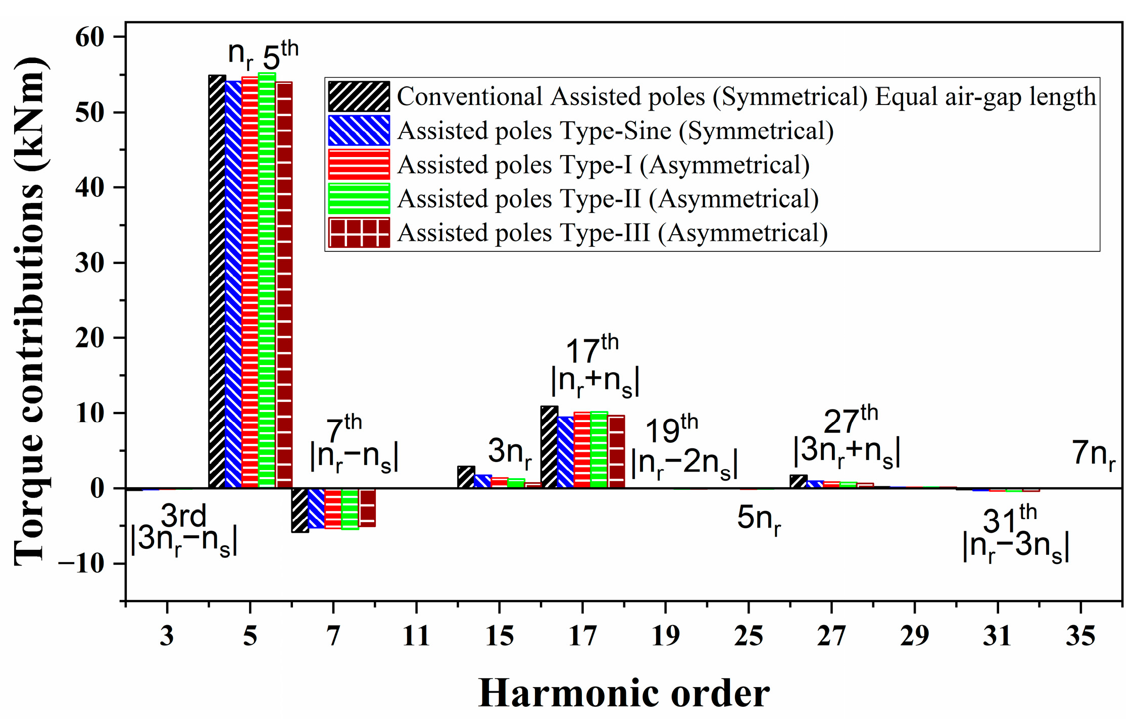
The torque contributions from the respective air-gap flux density harmonic components for the analyzed machine designs are presented in Figure 3. It is evident from Figure 3 that the primary component contributing to torque is nr (5th), with additional significant contributions from modulated field harmonics, such as |nrns| (7th), 3nr (15th), and |nr + ns| (17th), along with other minor modulated harmonics. Moreover, the torque contribution originating from the primary order harmonic nr (5th) is relatively higher in the case of a conventional rotor design with equal air-gap length and symmetrical assisted-poles. The 7th harmonic order also contributes a negative torque proportion in both cases. Torque contributions from the modulated field harmonics are also obtained, as can be seen in Figure 3.

3.5. Back-EMF Response

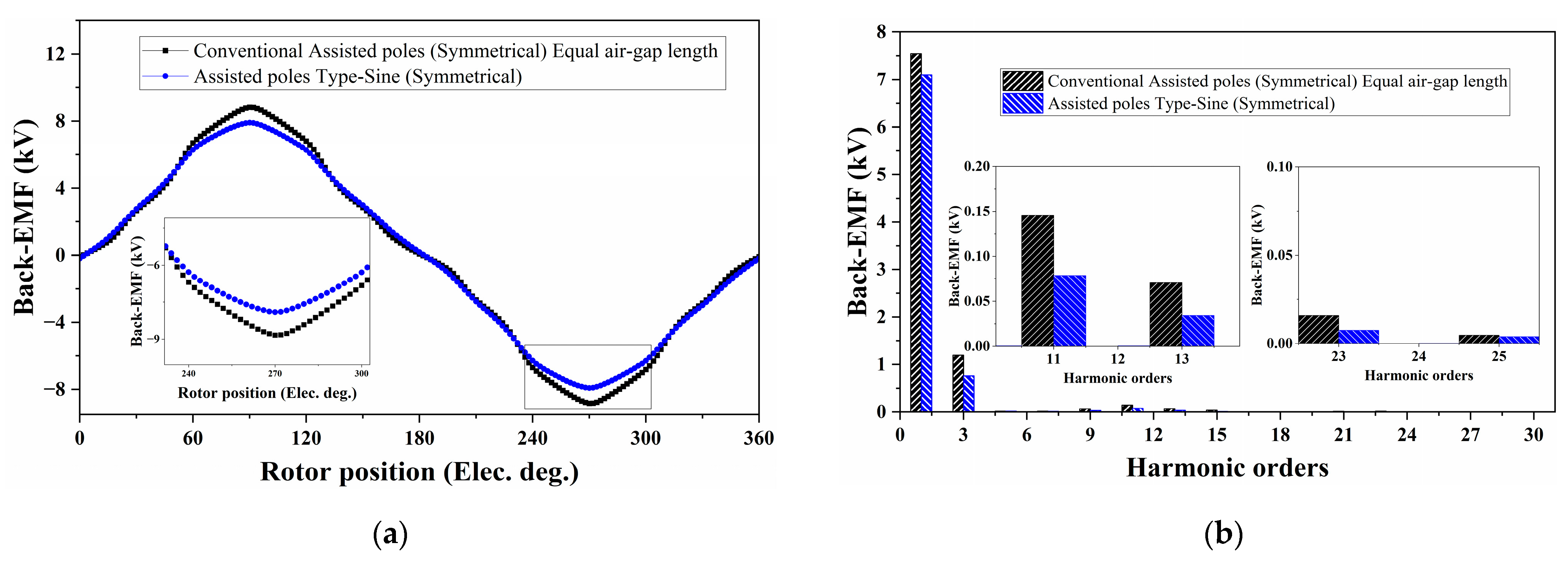
The back-EMFs for the analyzed machine design cases with symmetrical assisted-poles are given in Figure 4a, while a comparison of their FFT analysis is shown in Figure 4b. For the analyzed spoke-type PMSM, the torque ripples (first and second) order are generated by the harmonics in back-EMF, (11th and 13th) and (23rd and 25th), respectively. Figure 4b illustrates that the 11th and 13th back-EMF harmonics for the machine with symmetrically designed assisted-poles (Type-sine) are reduced by 46.20% and 51.42% in comparison to the machine having conventional (equal air-gap) length and symmetrically designed assisted-poles.
Table 3 presents a comparison of the back-EMF harmonics for the machine prototypes having symmetrically designed assisted-poles. The amplitudes of the 11th and 13th back-EMF harmonics for the machine designs with symmetrical (Type-sine) assisted-poles are suppressed in comparison to the machine having conventional (equal air-gap) length and symmetrically designed assisted-poles. Similarly, the 23rd and 25th back-EMF harmonics are also reduced significantly.

3.6. Generated Torque and Torque Ripple Comparison

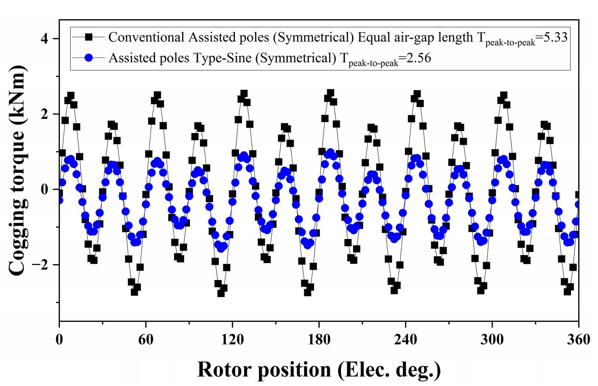
The cogging torque for the machine designs with symmetrically designed assisted-poles is shown in Figure 5. The cogging torque (peak-to-peak) for the machine designs with symmetrical (Type-sine) assisted-poles is reduced in comparison to the conventional symmetrical assisted pole design of the machine prototype, as shown in Table 4.
The machine torque performance for the symmetrical assisted-pole designs is presented in Figure 6a. The torque ripples in the machine design with symmetrical (Type-sine) assisted-poles are smaller compared to the conventional symmetrical assisted-poles’ design of the machine.
The FFT of the generated torque for the machine symmetrical assisted-poles design cases is shown in Figure 6b. The first and second-order torque ripple harmonics (h ± 1 = 12) and (h ± 1 = 24) are reduced for the symmetrical (Type-sine) assisted-poles design of the machine due to the suppression in the corresponding torque ripple producing harmonics validating the analytical investigation presented in Section 3.

4. Torque Ripple Reduction through Asymmetrically Designed Assisted-Poles

Based on the analysis presented above, asymmetrical designs of the assisted-poles for the spoke-type PMSM are investigated in this section to examine the generated torque and torque ripple response. Rotor designs with assisted-poles having unequal pole–arc ratios (λ1λ2) are chosen in this analysis. The Fourier series expansion of the air-gap flux density waveform under asymmetrically designed assisted-poles is given by
B a g θ = h = 1 B a g , h cos ( n p θ )
For symmetrically designed assisted-poles, the pole–arc ratio and the magnetic flux from adjacent assisted-poles are equal (λ1 = λ2) and (Bag1 = Bag2); therefore (Bag1λ1 = Bag2λ2). However, for the asymmetrically designed assisted-poles, the pole–arc ratio and the air-gap flux distribution are not the same (λ1λ2) and (Bag1Bag2), so therefore (Bag1λ1Bag2λ2). The modified air-gap flux density for the asymmetrically designed assisted-poles case is given by
B a g , h θ = B a g , 1 n π sin λ 1 2 h π + ( 1 ) h + 1 λ 1 λ 2 sin λ 2 2 h π
where Bag1 represents the air-gap flux density due to the rotor-designed assisted-poles with a larger pole–arc ratio. The torque ripples are caused by the (mNq,2p/p ± 1) rotor-induced MMF harmonic orders, as shown in (14) and (15); therefore, they need to be eliminated. The first two torque ripples are produced by m = 1 and m = 2, corresponding to the rotor-induced MMF harmonics, which need to be eliminated. Since (mNq,2p/p ± 1) is odd, therefore (h + 1) becomes even, so (17) can be expressed as
B a g , h θ = B a g , 1 h π sin λ 1 2 h π + B a g , 1 h π λ 1 λ 2 sin λ 2 2 h π
Considering (Bag,1/hπ = C1) and (Bag,1 λ1/hπλ2 = C2), and to minimize the amplitude of Bag,h expression (18) is simplified as given below.
sin λ 1 2 h π + sin λ 2 2 h π = 0
Expanding (19) results in
sin λ 1 2 h π + sin λ 2 2 h π = 2 sin ( λ 1 + λ 2 ) 4 h π cos ( λ 1 λ 2 ) 4 h π
It can be seen from (20) that either the first or second part needs to be equal to 0, as expressed below.
sin ( λ 1 + λ 2 ) 4 h π = 0 or   cos ( λ 1 λ 2 ) 4 h π = 0
The second condition of (21) is more valid since, for the first one, the pole–arc ratio is too small (not practical).
cos ( λ 1 λ 2 ) 4 h π = 0 ( λ 1 λ 2 ) 4 h π = π 2
Simplifying,
λ 1 λ 2 = 2 h = 2 m N q 2 p p ± 1
The dimensions of the asymmetrically designed assisted-poles for the analyzed spoke-type PMSM and the corresponding torque ripples producing harmonics can be obtained from the expression (23). The asymmetrically designed assisted-poles’ arc ratio should satisfy (24) to minimize the corresponding torque ripple-producing harmonic orders.
λ 1 λ 2 = 2 11 f o r     ( h = 11 ) λ 1 λ 2 = 2 13 f o r     ( h = 13 ) λ 1 λ 2 = 2 23 f o r     ( h = 23 ) λ 1 λ 2 = 2 25 f o r     ( h = 25 ) . .
Expression (24) presents detailed guidelines on selecting pole–arc ratio for the asymmetrical design of the assisted-poles to optimize the concerned harmonic orders, which generate torque ripples. The first-order torque ripple is minimized by selecting the pole–arc ratio to be λ1 − λ2 = 0.18 for h = 11 or λ1 − λ2 = 0.15 for h = 13 for the best possible results. Henceforth, the best possible range for the asymmetrically designed assisted pole–arc ratio to minimize the first-order torque ripple due to (h = 11 and h = 13) harmonics can be from 0.13 to 0.20. A similar approach can be followed to select the optimized values for the pole–arc ratio, aiming to minimize the required torque ripple-producing harmonics. A detailed investigation of the analytical calculation is presented next.

5. Validation of Torque Ripple Reduction through Asymmetrically Designed Assisted Poles

The analytical investigation of torque ripple reduction is validated in this section for the spoke-type PMSM designs with rotors having asymmetrically designed assisted-poles. Three different types of assisted-poles are chosen for analysis, as shown in Figure 7. A detailed optimization analysis of the rotor-designed assisted poles-arc ratio is conducted for each design type. A comparative analysis of the torque response for the machine prototype having asymmetrically designed assisted-poles (Type-1) is presented in Table 5. The larger pole–arc ratio (λ1) is fixed while the (λ2) pole–arc ratio is varied. Table 5 presents the generated torque, torque ripple, and cogging torque response under different pole–arc ratios. It can be observed from Table 5 that torque ripples and cogging torque response are the lowest when the pole–arc ratio is (λ1 − λ2 = 0.18), minimizing the first torque ripple-producing rotor-MMF harmonics validating the analysis presented.
The same pole–arc ratio optimization analysis is conducted for the spoke-type PMSM with asymmetrically designed assisted-poles (Type-II and Type-III) cases. Table 6 and Table 7 present a detailed analysis of the pole–arc optimization for the spoke-type PMSM having asymmetrically designed assisted-poles (Type-II and Type-III) cases. For the Type-II and Type-III designs, the torque ripples and cogging torque response are also the lowest by selecting the pole–arc ratio to be λ1λ2 = 0.18, minimizing the first torque ripple producing rotor-MMF harmonics (h = 11 and h = 13). According to the analysis presented, the proposed method validates the torque ripple reduction by selecting the proper asymmetrical rotor-designed assisted-poles arc ratio.

6. FEA Validation and Comparative Analysis of Machine Designs with Symmetrical and Asymmetrical Assisted-Poles

6.1. Air-Gap Flux Density and Average Torque Response

The distribution of air-gap flux density and the corresponding harmonic order analysis presented in Section 2 are applied to the symmetrically and asymmetrically designed cases of the assisted-poles for the machine prototype. The analysis is conducted considering the optimized values for the pole–arc ratio λ1λ2 = 0.18 for the asymmetrical designs of the assisted-pole types. Figure 8a,b presents a comparative analysis of the air-gap flux density (radial and tangential) harmonics for the analyzed machine designs.
It can be seen from the comparative analysis of the air-gap flux density harmonics for the symmetrical and asymmetrical assisted-poles designs of the machine prototype that, nr (5th) equal to the number of pole pairs is the main harmonic order, while there are considerable modulated field harmonics as can be seen in Figure 8a,b. The torque contributions from the corresponding air-gap flux density harmonics are presented in Figure 9 for the machine’s symmetrical and asymmetrical assisted-pole structures. Here also, it can be observed that (5th-order) harmonic is the main torque-contributing component for all the design cases, while the major torque-contributing modulated field harmonics include |nrns| (7th), 3nr (15th), and |nr + ns| (17th), besides other small contributing modulated harmonics.

6.2. Back-EMF Response Analysis

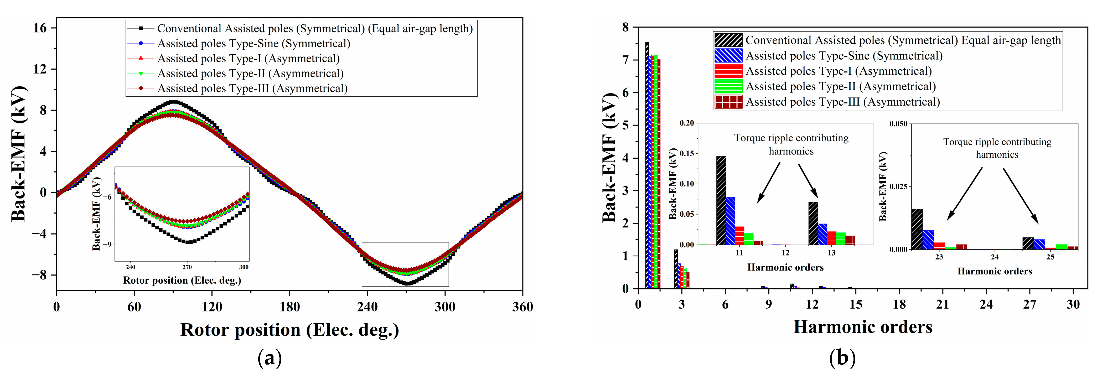
The back-EMFs for the analyzed machine design cases with symmetrical and asymmetrical assisted-poles operated at 60 rpm are given in Figure 10a, while the comparison of their FFT analysis is shown in Figure 10b. The torque ripples (first-order) for the analyzed three-phase spoke-type PMSM are generated by the (11th and 13th) back-EMF harmonics, while the 23rd and 25th-order back-EMF harmonics generate the second-order torque ripples. Figure 10b illustrates that the 11th and 13th back-EMF harmonics for the machine designs having asymmetrically designed assisted-poles are greatly reduced in comparison to the machine designs with symmetrically designed assisted-poles. Similarly, the 23rd and 25th-order back-EMF harmonics are also considerably reduced for the machine prototype’s asymmetrically designed assisted-poles’ structure. Table 8 presents a comparison of the back-EMFs harmonics for the analyzed machine design cases.
Similarly, it is evident from Table 8 that the amplitudes of the back-EMF harmonics (11th and 13th) for the machine having asymmetrically designed assisted-poles are suppressed by (80% and 68.57%) for the Type-I, suppressed by (87.58% and 72.85%) for the Type-II and suppressed by (95.86% and 80%) for the Type-III, design in comparison to the conventional symmetrically designed assisted-poles structure of the machine prototype. Henceforth, the 12th-order torque ripple can be minimized considerably. Similarly, the 23rd and 25th back-EMF harmonics are also reduced significantly.

6.3. Torque Response Analysis

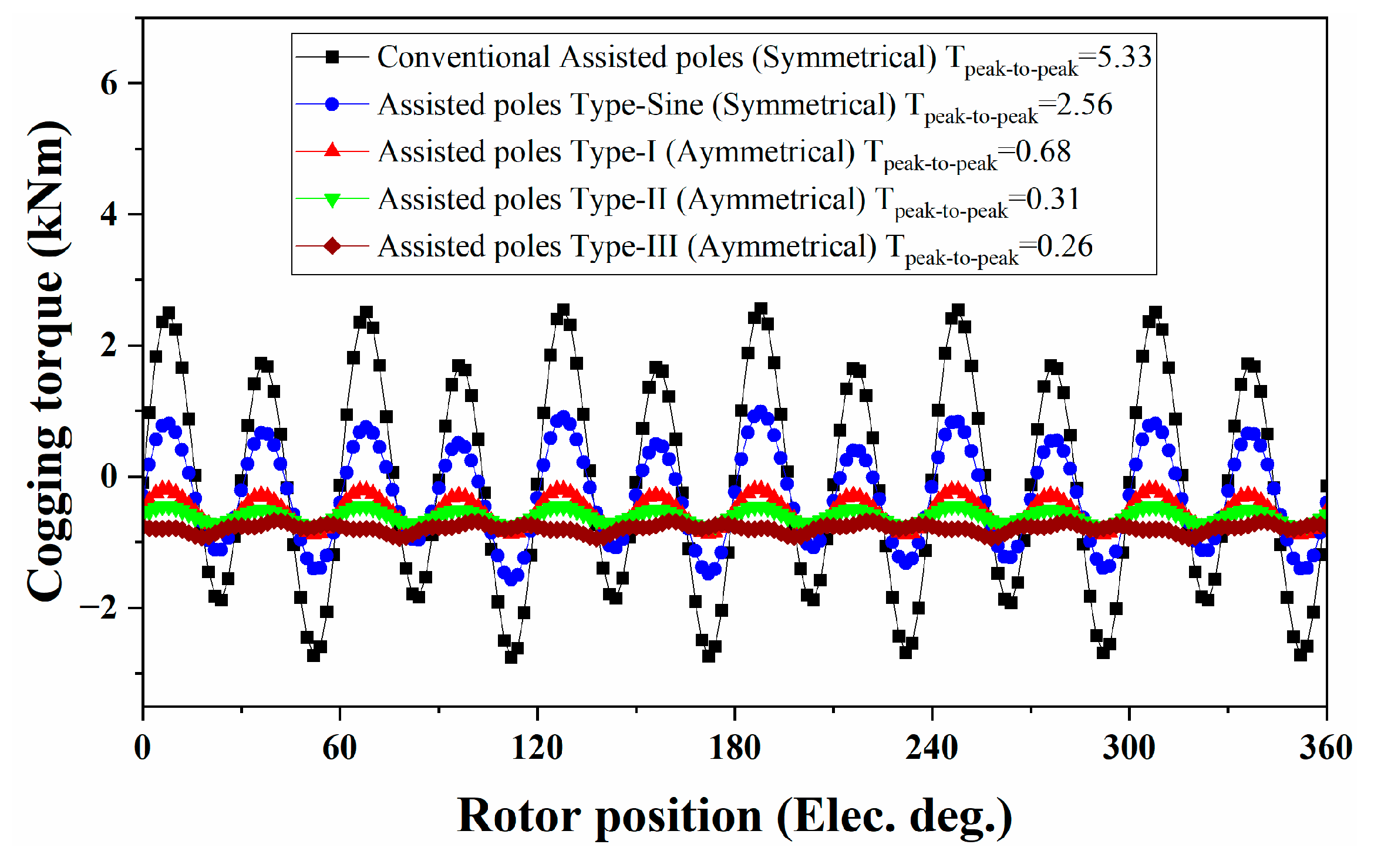
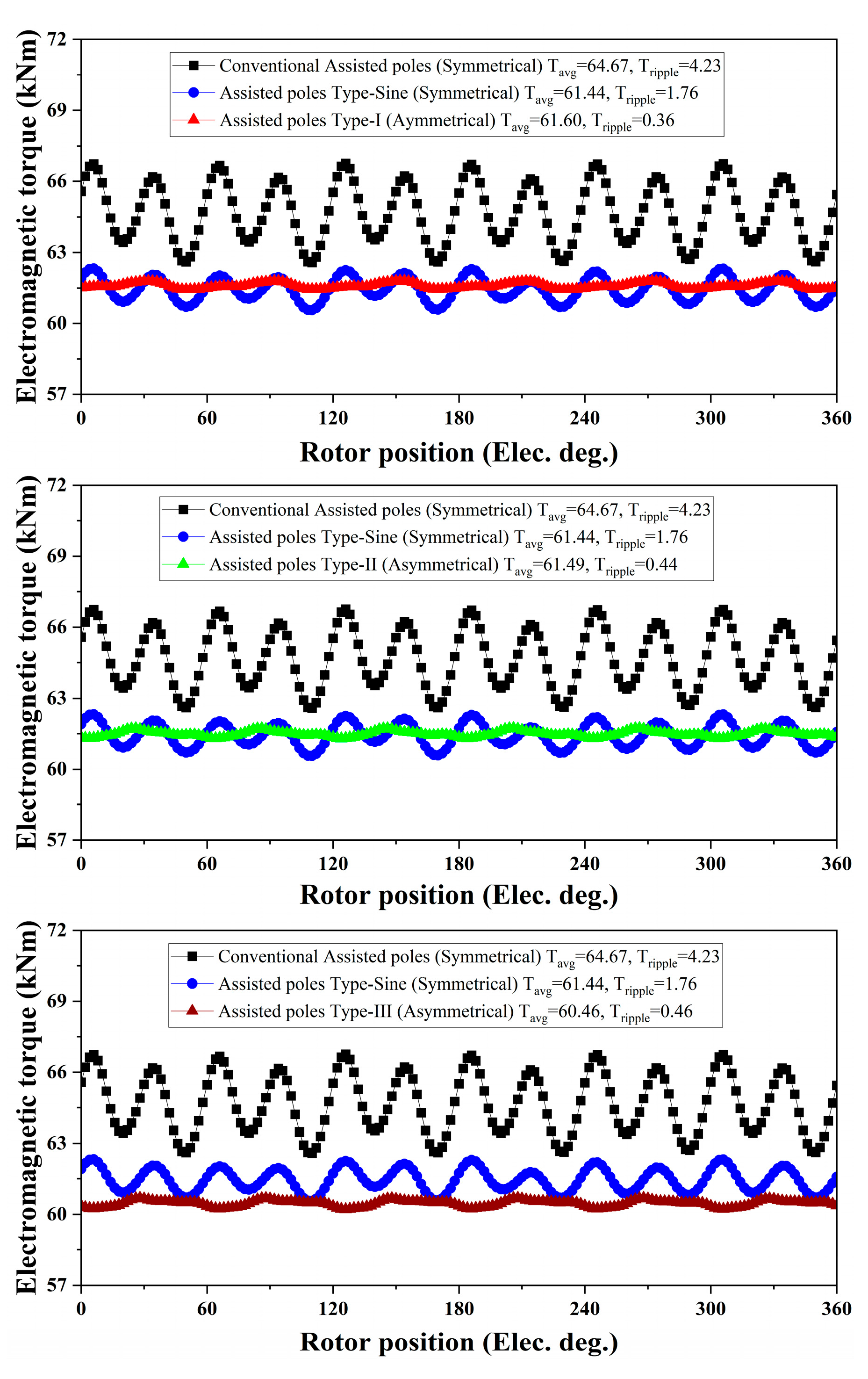
The cogging torque waveforms for the analyzed machine design cases with symmetrical and asymmetrical assisted-poles are shown in Figure 11. The cogging torque (peak-to-peak) for the machine designs having asymmetrical assisted-poles is greatly reduced in comparison to the machine designs having symmetrical assisted-poles shown in Table 9. The torque performance of the machine prototype for the analyzed symmetrical and asymmetrical assisted-poles designs is presented in Figure 12 and Table 9.
It can be seen that the torque ripples of the machine designs having asymmetrical assisted-poles are much smaller compared to the symmetrical design cases. However, the average torque in symmetrically designed assisted pole types is a little higher due to the higher main-order air-gap flux density harmonic, as shown in Figure 8. The torque ripples for the machine designs having asymmetrically designed assisted-poles are suppressed by (91.48%) for the Type-I, (88.65%) for the Type-II, and by (89.12%) for the Type-III design in comparison to the conventional symmetrical assisted-poles design of the machine prototype.
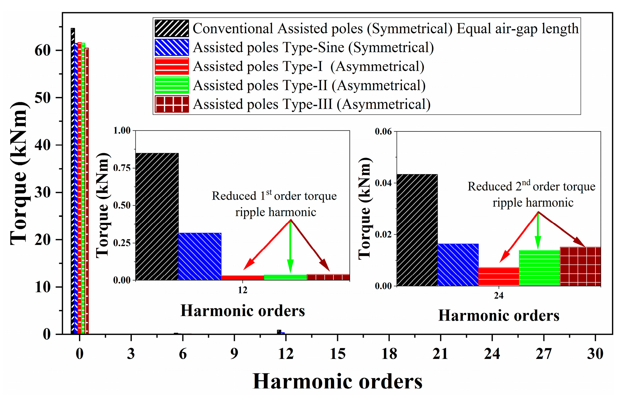
The FFT analysis of the generated torque for the analyzed design cases is shown in Figure 13. The first and second-order torque ripple harmonics (h ± 1 = 12) and (h ± 1 = 24) are significantly reduced, as shown in Figure 13, for the asymmetrically designed assisted-pole structure of the machine prototype. This validates the analytical investigation of selecting the optimal pole–arc ratio for the machine designs having asymmetrical assisted-poles, presented in Section 4.
The torque performance under different current angles is presented in Figure 14 for the spoke-type PMSM with symmetrical and asymmetrical assisted-poles. Figure 14a presents the torque, while Figure 14b presents the torque ripple performance under different current angles. Here, it can also be observed that the spoke-type PMSM designed according to the proposed asymmetrically designed assisted-poles arc-ratio significantly reduces the torque ripples, validating the proposed method.

7. Conclusions

This article investigates a low-speed, high-torque density spoke-type PMSM with symmetrical and asymmetrical assisted-poles. Firstly, the investigation of air-gap flux density harmonics, the generated torque, and the torque ripple analysis is presented and validated through analytical and FEA calculations. Secondly, a correlation is developed between the magnitudes of the torque ripple and the stator and rotor-magnetomotive force (MMF) harmonics in a spoke-type PMSM with FSCW configuration. Furthermore, an investigation is conducted to identify the torque ripple resulting from slot harmonics. In order to mitigate this torque ripple, the implementation of asymmetrical assisted-poles is employed. Additionally, a generic principle for torque ripple reduction is derived and validated through FEA and analytical calculations for FSCW spoke-type PMSMs having asymmetrical assisted-poles. Some of the other main findings from this study are listed below.
(1)
The air-gap magnetic flux density harmonic order (nr), equal to the number of pole pairs, is the main (air-gap flux density and torque producing) harmonic component for the spoke-type PMSM having symmetrical and asymmetrical designs of the assisted-poles and having FSCW configuration. Additionally, modulated air-gap magnetic field harmonics, which contribute a considerable portion to overall air-gap flux density distribution and torque production, are also explored.
(2)
By analyzing the assisted-poles geometries (symmetrical and asymmetrical) for the machine prototype, it has been established that the pole–arc ratio in the case of asymmetrically designed assisted-poles can be varied to obtain optimized values, which can eliminate the corresponding torque ripple producing rotor-MMF harmonics resulting in reduced torque ripples and cogging torque.
(3)
The proposed generalized torque ripple reduction technique can be applied to different designs of the machine prototype having asymmetrically designed assisted-poles to reduce the corresponding torque ripples through the proposed pole–arc ratio selection technique.
(4)
In further research, the impact of asymmetrical assisted-poles designs on the radial forces, vibration, and noise response will be investigated to analyze the machine prototype for its vibro-acoustic behavior.

Author Contributions

Conceptualization, S.H.S. and J.-X.S.; methodology, S.H.S. and Y.-C.W.; software, S.H.S. and D.S.; validation, S.H.S. and J.-X.S.; formal analysis, S.H.S.; investigation, S.H.S.; resources, J.-X.S. and Y.-C.W.; data curation, S.H.S.; writing—original draft preparation, S.H.S.; writing—review and editing, S.H.S. and J.-X.S.; visualization, S.H.S.; supervision, J.-X.S.; project administration, J.-X.S.; funding acquisition, J.-X.S. All authors have read and agreed to the published version of the manuscript.

Funding

This work was supported by the National Key Research and Development Program of China (2022YFB3403100).

Data Availability Statement

The data presented in this study are available on request from the corresponding author. The data are not publicly available due to privacy.

Conflicts of Interest

The authors declare no conflicts of interest.

References

  1. Boldea, I.; Tutelea, L.N.; Parsa, L.; Dorrell, D.G. Automotive Electric Propulsion Systems with Reduced or No Permanent Magnets: An Overview. IEEE Trans. Ind. Electron. 2014, 61, 5696–5711. [Google Scholar] [CrossRef]
  2. El-Refaie, A. Fractional-slot Concentrated-windings Synchronous Permanent Magnet Machines: Opportunities and Challenges. IEEE Trans. Ind. Electron. 2010, 57, 107–121. [Google Scholar] [CrossRef]
  3. Morimoto, S.; Ooi, S.; Inoue, Y.; Sanada, M. Experimental Evaluation of a Rare-earth-free Pmasynrm with Ferrite Magnets for Automotive Applications. IEEE Trans. Ind. Electron. 2014, 61, 5749–5756. [Google Scholar] [CrossRef]
  4. Kim, S.-I.; Park, S.-H.; Park, T.; Cho, J.; Kim, W.-H.; Lim, S. Investigation and Experimental Verification of a Novel Spoke-type Ferrite-magnet Motor for Electric-vehicle Traction Drive Applications. IEEE Trans. Ind. Electron. 2014, 61, 5763–5770. [Google Scholar] [CrossRef]
  5. Liu, G.; Zhipeng, L.; Zhao, W.; Chen, Q.; Xu, G. Third Harmonic Current Injection in Fault-tolerant Five-phase Permanent-magnet Motor Drive. IEEE Trans. Power Electron. 2018, 33, 6970–6979. [Google Scholar] [CrossRef]
  6. Jia, H.; Cheng, M.; Hua, W.; Zhao, W.; Li, W. Torque Ripple Suppression in Flux-switching PM Motor by Harmonic Current Injection Based on Voltage Space-vector Modulation. IEEE Trans. Magn. 2010, 46, 1527–1530. [Google Scholar] [CrossRef]
  7. Chen, Q.; Zhao, W.; Liu, G.; Zhipeng, L. Extension of Virtual-signal-injection-based MTPA Control for Five-phase IPMSM into Fault-tolerant Operation. IEEE Trans. Ind. Electron. 2019, 66, 944–955. [Google Scholar] [CrossRef]
  8. Carraro, E.; Bianchi, N.; Zhang, S.; Koch, M. Design and Performance Comparison of Fractional Slot Concentrated Winding Spoke Type Synchronous Motors with Different Slot-pole Combinations. IEEE Trans. Ind. Appl. 2018, 54, 2276–2284. [Google Scholar] [CrossRef]
  9. Chen, Q.; Liu, G.; Gong, W.; Qu, L.; Zhao, W.; Shen, Y. Design of a Spoke-type Permanent-magnet Motor with Optimal Winding Configuration for Electric Vehicle Applications. J. Appl. Phys. 2012, 111, 07E710. [Google Scholar] [CrossRef]
  10. Zhao, W.; Lipo, T.A.; Kwon, B.-I. Dual-stator Two-phase Permanent Magnet Machines with Phase-group Concentrated-coil Windings for Torque Enhancement. IEEE Trans. Magn. 2015, 51, 8112404. [Google Scholar] [CrossRef]
  11. Hwang, K.-Y.; Rhee, S.-B.; Yang, B.-Y.; Kwon, B.-I. Rotor Pole Design in Spoke-type Brushless DC Motor by Response Surface Method. IEEE Trans. Magn. 2007, 43, 1833–1836. [Google Scholar] [CrossRef]
  12. Liu, F.; Zhu, X.; Wu, W.; Quan, L.; Xiang, Z.; Hua, Y. Design and Analysis of an Interior Permanent Magnet Synchronous Machine with Multiflux-barriers Based on Flux-intensifying Effect. IEEE Trans. Appl. Supercond. 2018, 28, 5201005. [Google Scholar] [CrossRef]
  13. Chen, Q.; Liu, G.; Zhao, W.; Mingming, S.; Liu, Z. Design and Analysis of the New High-reliability Motors with Hybrid Permanent Magnet Material. IEEE Trans. Magn. 2014, 50, 8207010. [Google Scholar] [CrossRef]
  14. Liang, P.; Chai, F.; Yu, Y.; Chen, L. Analytical Model of a Spoke-type Permanent Magnet Synchronous In-wheel Motor with Trapezoid Magnet Accounting for Tooth Saturation. IEEE Trans. Ind. Electron. 2019, 66, 1162–1171. [Google Scholar] [CrossRef]
  15. Zhao, W.; Kwon, J.-W.; Wang, X.; Lipo, T.A.; Kwon, B.-I. Optimal Design of a Spoke-type Permanent Magnet Motor with Phase-group Concentrated-coil Windings to Minimize Torque Pulsations. IEEE Trans. Magn. 2017, 53, 8104604. [Google Scholar] [CrossRef]
  16. Zhang, P.; Sizov, G.Y.; Ionel, D.M.; Demerdash, N.A.O. Establishing the Relative Merits of Interior and Spoke-type Permanent-magnet Machines with Ferrite or Ndfeb Through Systematic Design Optimization. IEEE Trans. Ind. Appl. 2015, 51, 2940–2948. [Google Scholar] [CrossRef]
  17. Zhao, W.; Ma, A.; Ji, J.; Chen, X.; Yao, T. Multiobjective Optimization of a Double-side Linear Vernier PM Motor Using Response Surface Method and Differential Evolution. IEEE Trans. Ind. Electron. 2020, 67, 80–90. [Google Scholar] [CrossRef]
  18. Ge, X.; Zhu, Z.-Q.; Li, J.; Chen, J.T. A Spoke-type IPM Machine with Novel Alternate Airspace Barriers and Reduction of Unipolar Leakage Flux by Step-staggered Rotor. IEEE Trans. Ind. Appl. 2016, 52, 4789–4797. [Google Scholar] [CrossRef]
  19. Chen, Q.; Xu, G.; Zhai, F.; Liu, G. A Novel Spoke-type PM Motor with Auxiliary Salient Poles for Low Torque Pulsation. IEEE Trans. Ind. Electron. 2020, 67, 4762–4773. [Google Scholar] [CrossRef]
  20. Chen, Q.; Xu, G.; Liu, G.; Zhao, W.; Liu, L.; Lin, Z. Torque Ripple Reduction in Five-phase IPM Motors by Lowering Interactional MMF. IEEE Trans. Ind. Electron. 2018, 65, 8520–8531. [Google Scholar] [CrossRef]
  21. Fornasiero, E.; Bianchi, N.; Bolognani, S. Slot Harmonic Impact on Rotor Losses in Fractional-slot Permanent-magnet Machines. IEEE Trans. Ind. Electron. 2012, 59, 2557–2564. [Google Scholar] [CrossRef]
  22. Shah, S.H.; Wang, Y.; Shi, D.; Shen, J.-X. Investigation of Air-gap Magnetic Field Harmonics and Generated Torque in Low-speed High-power Density Spoke-type FSCW Pmsms. In Proceedings of the 2023 26th International Conference on Electrical Machines and Systems (ICEMS), Zhuhai, China, 5–8 November 2023; pp. 4269–4274. [Google Scholar] [CrossRef]
  23. Shah, S.H.; Wang, Y.; Shi, D.; Zhu, Z.; Shen, J.-X. Investigation of Low-speed High-power Density Spoke-type FSCW PMSM with Similar PM Volume and Different Shapes Considering Magnetic Gearing Effect. In Proceedings of the 2023 26th International Conference on Electrical Machines and Systems (ICEMS), Zhuhai, China, 5–8 November 2023; pp. 4660–4665. [Google Scholar] [CrossRef]
Figure 1. Analyzed designs of the prototype machine: (a) Assisted-poles symmetrical designs; (b) Assisted-poles asymmetrical design types.
Machines 12 00327 g001
Figure 2. Harmonics in the air-gap flux density for the analyzed machine designs: (a) Radial harmonic orders; (b) Tangential harmonic orders.
Machines 12 00327 g002
Figure 3. Air-gap flux density harmonic orders and torque contributions from symmetrical assisted-poles design cases.
Machines 12 00327 g003
Figure 4. Back-EMF of the analyzed machine designs: (a) Waveforms; (b) Harmonic orders.
Machines 12 00327 g004
Figure 5. Cogging torque waveforms for the analyzed machine designs.
Machines 12 00327 g005
Figure 6. Generated torque for the analyzed machine designs: (a) waveform; (b) FFT analysis of the generated torque.
Machines 12 00327 g006
Figure 7. Analyzed designs of the prototype machine with rotors having asymmetrical assisted-poles: (a) Type-I; (b) Type-II; (c) Type-III.
Machines 12 00327 g007
Figure 8. Air-gap flux density for the analyzed machine designs: (a) Radial harmonic orders; (b) Tangential harmonic orders.
Machines 12 00327 g008
Figure 9. Air-gap flux density harmonic orders and torque contributions for all the design cases.
Machines 12 00327 g009
Figure 10. Machines back-EMF response: (a) Waveforms; (b) Harmonic orders.
Machines 12 00327 g010
Figure 11. Cogging torque response for the machine prototypes.
Machines 12 00327 g011
Figure 12. Generated torque response for the machine prototypes.
Machines 12 00327 g012
Figure 13. Generated torque FFT for the machine prototypes.
Machines 12 00327 g013
Figure 14. Machine designs torque response at different current angles: (a) Average torque; (b) Torque ripples.
Machines 12 00327 g014
Table 1. Design parameters for the spoke-type PMSM with symmetrical and asymmetrical assisted-poles.
SpecificationsSymmetric DesignAsymmetric Design
Conventional
Design
Type-SineType-IType-IIType-III
Slots/poles72/60
Stator outer diameter1610 (mm)
Stator inner diameter1360 (mm)
Rotor outer diameter1354 (mm)
Rotor inner diameter1264 (mm)
λ1 pole–arc ratio0.870.870.840.77
λ2 pole–arc ratio0.870.690.660.59
λ1 − λ2--0.180.180.18
PM width20 (mm)
PM height40 (mm)
Machine speed60 (rpm)
Rated power400 (kW)
Air-gap length3 (mm)
Table 2. Air-gap flux density harmonic orders due to permanent magnets and the armature reaction components.
PM Air-Gap Magnetic Flux DensityAR Air-Gap Magnetic Flux Density
HarmonicsMechanical speed of rotationHarmonicsMechanical speed of rotation
i n r ω r v n s k , v n s m n r ω r k , n r ω r k
| i n r ± v n s | i n r ω r i n r ± v n s | k ± v n s | ,
| m ± v n s |
n r ω r k ± v n s , n r ω r k m ± v n s
Table 3. Main torque ripples contributing back-EMF harmonics for the analyzed machine designs.
Machine DesignsBack-EMF Harmonics (kV)
1st11th13th23rd25th
Conventional Assisted-poles (Symmetrical)7.540.1450.0700.0160.004
Assisted-poles Type-Sine (Symmetrical)7.0990.0780.0340.0070.003
Table 4. Generated torque, torque ripples, and cogging torque response for the analyzed machine designs.
Machine DesignsTavg (kNm)Tripples (kNm)Tcogging (Peak-to-Peak) (kNm)
Conventional Assisted-poles (Symmetrical)64.674.235.33
Assisted-poles Type-Sine (Symmetrical)61.441.762.56
Table 5. Optimization of the pole–arc ratio for the machine design with asymmetrical assisted-poles Type-I.
Assisted-Poles–Arc RatioTavg (kNm)Tripples (kNm)Tcogging (Peak-to-Peak) (kNm)
λ1λ2λ1 − λ2
0.870.820.0462.001.6572.528
0.790.870.0861.951.362.19
0.760.870.1161.850.961.70
0.720.870.1461.740.621.15
0.690.870.1861.600.360.68
0.660.870.2161.430.420.41
0.620.870.2461.240.590.40
0.590.870.2861.020.740.73
0.560.870.3160.771.101.24
0.520.870.3460.501.801.99
0.490.870.3860.182.02.42
0.460.870.4159.842.312.74
0.420.870.4459.482.332.80
Table 6. Optimization of the pole–arc ratio for the machine design with asymmetrical assisted-poles Type-II.
Assisted-Poles–Arc RatioTavg (kNm)Tripples (kNm)Tcogging (Peak-to-Peak) (kNm)
λ1λ2λ1 − λ2
0.790.840.0461.921.171.92
0.760.840.0861.830.801.46
0.720.840.1161.720.510.95
0.690.840.1461.590.500.51
0.660.840.1861.490.440.31
0.620.840.2161.240.490.28
0.590.840.2461.030.580.59
0.560.840.2860.790.901.06
0.520.840.3160.521.351.67
0.490.840.3460.221.772.19
0.460.840.3859.892.052.50
0.240.840.4159.542.142.54
0.390.840.4459.171.8782.82
Table 7. Optimization of the pole–arc ratio for the machine design with asymmetrical assisted-poles Type-III.
Assisted-Poles–Arc RatioTavg (kNm)Tripples (kNm)Tcogging (Peak-to-Peak) (kNm)
λ1λ2λ1 − λ2
0.720.770.0461.091.090.81
0.690.770.0860.970.680.10
0.660.770.1160.810.770.27
0.620.770.1460.650.690.28
0.590.770.1860.460.460.26
0.560.770.2160.200.550.65
0.520.770.2459.950.971.19
0.490.770.2859.671.361.65
0.460.770.3159.371.561.93
0.420.770.3459.071.571.88
0.390.770.3858.731.311.62
0.360.770.4158.350.731.06
0.320.770.4457.930.790.49
Table 8. Back-EMF for the symmetrical and asymmetrical assisted-pole machine designs.
Machine DesignsBack-EMF Harmonics (kV)
1st11th13th23rd25th
Conventional Assisted-poles (Symmetrical)7.540.1450.0700.0160.004
Assisted-poles Type-Sine (Symmetrical)7.0990.0780.0340.0070.003
Assisted-poles Type-I (Asymmetrical)7.1550.0290.0220.0020.0007
Assisted-poles Type-II (Asymmetrical)7.1440.0180.0190.00080.002
Assisted-poles Type-III (Asymmetrical)7.0250.0060.0140.0020.001
Table 9. Torque response for the machine designs with symmetrical and asymmetrical assisted-poles.
Machine DesignsTavg (kNm)Tripples (kNm)Tcogging (Peak-to-Peak) (kNm)
Conventional Assisted-poles (Symmetrical)64.674.235.33
Assisted-poles Type-Sine (Symmetrical)61.441.762.56
Assisted-poles Type-I (Asymmetrical)61.600.360.68
Assisted-poles Type-II (Asymmetrical)61.430.480.25
Assisted-poles Type-III (Asymmetrical)60.460.460.26
Disclaimer/Publisher’s Note: The statements, opinions and data contained in all publications are solely those of the individual author(s) and contributor(s) and not of MDPI and/or the editor(s). MDPI and/or the editor(s) disclaim responsibility for any injury to people or property resulting from any ideas, methods, instructions or products referred to in the content.