Article

Mechanical Modeling of Viscous Fluid Damper with Temperature and Pressure Coupling Effects

1
College of Civil Engineering, Nanjing Tech University, Nanjing 211816, China
2
MCC Group, Central Research Institute of Building and Construction Co., Ltd., Beijing 100089, China
*
Author to whom correspondence should be addressed.
Machines 2024, 12(6), 366; https://doi.org/10.3390/machines12060366
Submission received: 9 April 2024 / Revised: 14 May 2024 / Accepted: 22 May 2024 / Published: 24 May 2024

Abstract

:
During long-duration dynamic loads, such as wind loads or seismic effects, the internal temperature and pressure of a damping cylinder escalate rapidly, which induce shifts in the mechanical attributes of viscous fluid dampers (VFDs). This study investigated the mechanical performance of VFD considering the coupling effects of temperature and pressure under long-duration loads. First, we analyzed the mechanical and energy-dissipation performances of the dampers based on the dynamic mechanical tests considering different loading frequencies, displacement amplitude, and loading cycles. The experimental results indicated that both temperature and pressure influenced the output of the dampers, and in the sealed environment of the damper pip, temperature and pressure exerted mutual influence. Furthermore, the relationship between the damping coefficient and temperature–pressure coupling effects was obtained. Subsequently, an improved mathematical model for the mechanical performance of a gap-type VFD was proposed by considering the macroscopic energy balance of the entire fluid within the damper. Finally, the accuracy of the mathematical model for VFD under long-duration dynamic loads was validated by comparing the computational results with the experimental data.

1. Introduction

Energy dissipation and seismic mitigation are highly promising passive damping techniques that have been extensively applied in the fields of civil engineering, mechanical engineering, and aerospace [1,2,3]. Among these, VFDs are particularly favored for their easy installation, the absence of initial stiffness, and robust energy dissipation capabilities, making them one of the most commonly used energy dissipation devices. Viscous damper technology encompasses innovations in structural design, investigations into damping mechanisms, the establishment of mechanical models, the dynamic analyses of damped structures, and the optimization of damper parameters and placement [4,5,6,7,8,9].
The core components of a VFD include a cylinder, piston, piston rod, damping fluid, end caps, and sealing elements [10,11]. Notably, there are gaps between the piston and cylinder, where variations significantly affect the damping characteristics. The damping coefficient is directly correlated with factors such as piston diameter, piston length, fluid dynamic viscosity, and fluid index. Conversely, it shows an inverse correlation with the clearance dimensions [12]. During operation, the piston undergoes reciprocating motion within the cylinder, causing the damping fluid to undergo extrusion and shear deformation. Typically, damper performance is minimally influenced by external conditions [13], and developing appropriate constitutive relationships for damping fluid flow within the cylinder can provide calculation formulas for the damping force in specific structural configurations [14,15]. However, under continuous seismic or wind loading, the internal fluid faces challenges in efficiently exchanging heat with the external environment due to the insulating properties of the cylinder. This leads to a rapid increase in fluid temperature, adversely affecting the operational efficacy of the damping device [16,17]. Given that the damping fluid in engineering structures is often a highly viscous, non-Newtonian fluid, rapid piston movements induce shear thinning [18]. Moreover, the viscosity of the damping fluid changes with temperature and pressure variations within the cylinder [19,20]. Sole reliance on computational fluid dynamics limits the exploration of fluid flow and heat transfer dynamics. The heating phenomenon within a VFD is intricately linked to the duration and amplitude of applied loads and the physical properties of the damping fluid. Research indicates that with an increase in frequency, the storage and loss moduli increase, the loss factor initially rises then falls, and the complex viscosity decreases. As temperatures rise, the storage modulus, loss modulus, and complex viscosity decrease, while the loss factor initially falls and then rises [21,22,23]. VFDs transform input seismic energy from kinetic to thermal form, elevating device temperature. The thermal expansion of the internal fluid increases internal pressure. While temperature increases under short-duration seismic loads marginally affect performance, these effects intensify under prolonged loads [24,25,26,27]. Data from Japan’s “311” seismic observation system showed a slow decay in the long-period component of seismic waves. In the later stages of an earthquake, the structural response is predominantly influenced by extended-period seismic forces [28], leading to significant damage and deformation. The effects of temperature on VFD performance during these periods are substantial. Previous studies have emphasized the impact of viscosity–temperature characteristics on damper performance, yet the effects of temperature-induced changes in internal cylinder pressure have received minimal attention. Recognizing the mutual effects of internal temperature and pressure within a cylinder allows for a more detailed assessment of damper functionality under extended seismic conditions.
The primary objective of this study was to ascertain the operational behavior of VFD under prolonged seismic loads by refining the mechanical model of these dampers. The mechanical performance of VFD is influenced not only by the construction of the damper and damping medium but also by the internal temperature and pressure within the cylinder. Consequently, it is imperative to propose theoretical models that can simultaneously consider the combined effects of temperature and pressure while addressing the loading frequency and displacement amplitude. To deduce the constitutive relationship accounting for the intertwined effects of temperature and pressure, an enhanced theoretical model was introduced. The model combined the macroscopic energy equation of the overall damper fluid, thermodynamic principles, and material tests of the damping medium. The precision and dependability of this model were verified through a meticulous comparison of numerical simulations and empirical data.

2. Experimental Study

The mechanical behavior of sealed dampers is closely related to the internal pressure, temperature, and external deformation of the outer cylinder. However, systematic studies on this complex issue are lacking. Mechanical performance tests were conducted to analyze the energy-dissipation performance of VFD under the coupling effects of multiple factors. In addition to basic mechanical performance tests, supplementary experiments were performed to explore the relationship between the damping force, temperature, and pressure variations.
The experimental study focused on gap-type viscous dampers. Two specimens were designed, with the key dimensions presented in Table 1, and detailed drawings shown in Figure 1a. As depicted in Figure 1c, two pressure sensors were installed on the outer cylinder of the damper to monitor changes in the internal cylinder pressure at various time intervals. The pressure sensors utilized in the experiment had a maximum range of 160 MPa and an accuracy of ±1.6%. Additionally, temperature strips were affixed to the outer cylinder to track temperature variations during the experiment. The viscous damping materials used were Wacker Silicone Fluids AK, with kinematic viscosities of 600,000 cSt and 80,000 cSt for the two specimens, respectively. In the experimental plan, the results of the two specimens will be compared to verify the accuracy of the tests. This comparison will also demonstrate how the mechanical performance of the VFDs changes under the simultaneous influence of temperature and pressure. Furthermore, additional temperature-controlled and shear tests conducted on the viscous damping liquids will be used to study the viscosity–temperature relationship and constitutive relationships of the viscous damping materials.
As shown in Figure 2, a hydraulic servo universal testing machine, produced by MTS Systems Corporation, was used to test the viscous damper specimens. The maximum loading displacement of the testing machine was up to 125 mm, and the working frequency was up to 100 Hz, meeting the frequency requirements for the dynamic test of the damper. The test device is composed of an electrohydraulic servo actuator, a dynamic displacement sensor, a force sensor, and a digital data acquisition system, with force measurement accuracy of ±0.5% and displacement measurement accuracy of ±0.5%. The upper and lower connectors of the damper were clamped using the hydraulic clamper of the test equipment to ensure a reliable connection and prevent slippage. During the entire test process, the loading displacement and damping force of the specimen were recorded by a force sensor and a displacement sensor connected to the actuator.
As depicted in Figure 3, the MCR302 rheometer was employed to investigate the relationship between the dynamic viscosity and temperature of the damping fluid. Featuring a permanent magnet DC motor, this rheometer is designed for its quick response capability. It applies stress to the specimen via a motor-driven fixture while measuring strain or rotational speed with an optical decoder, allowing for precise evaluations. The rheometer excels in high torque measurements without generating excessive heat or experiencing significant signal drift. It provides highly accurate measurements across a wide temperature range from −150 °C to 1000 °C. The device boasts a torque resolution of 0.0001 N·m with a minimum torque under rotation of 0.001 N·m and a maximum of 0.2 N·m, complemented by an angular displacement resolution of 0.001 degrees.
The damper was subjected to sinusoidal excitation μ = μ0 sin(ωt) loading. The experiment consisted of 13 loading conditions, which can be broadly categorized into four parts: ultimate displacement, low frequency (0.1 Hz), medium frequency (0.6 Hz), and durability performance. The specific loading conditions are listed in Table 2.

3. Results and Discussion

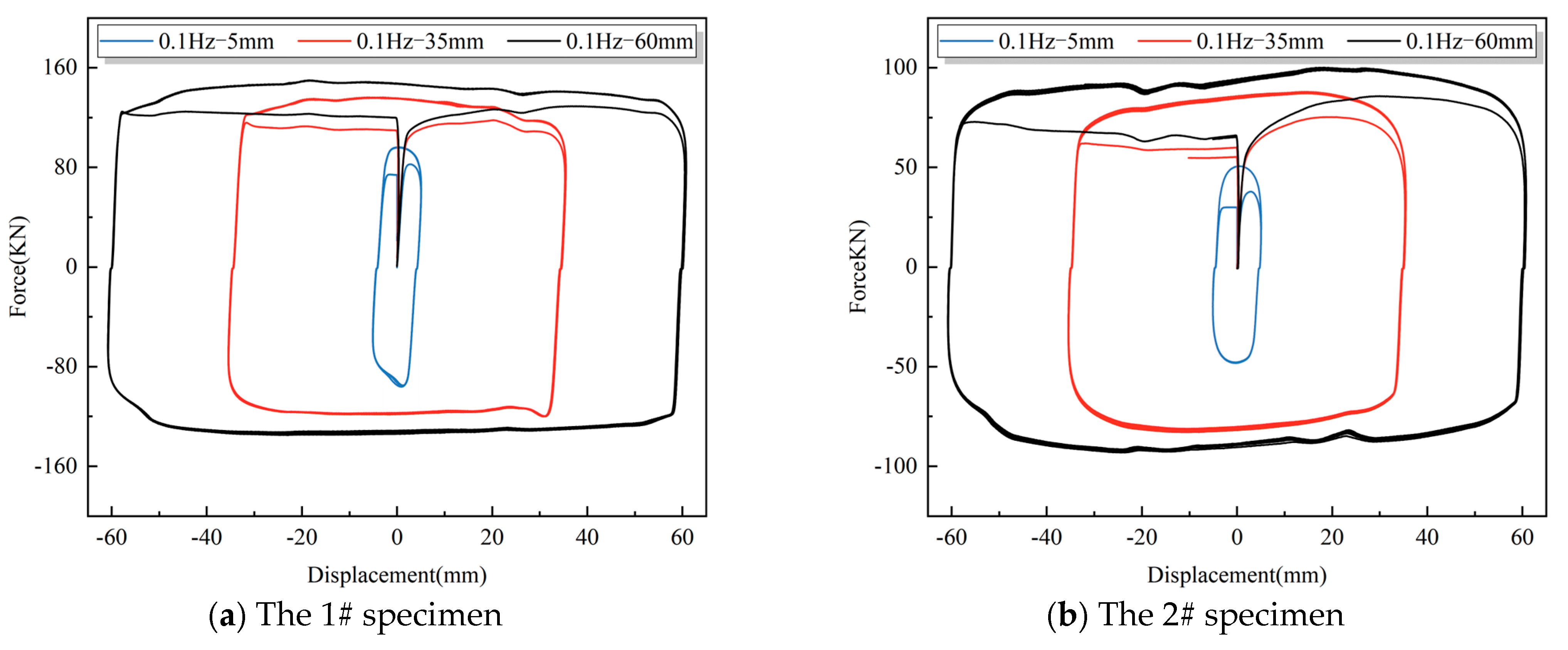
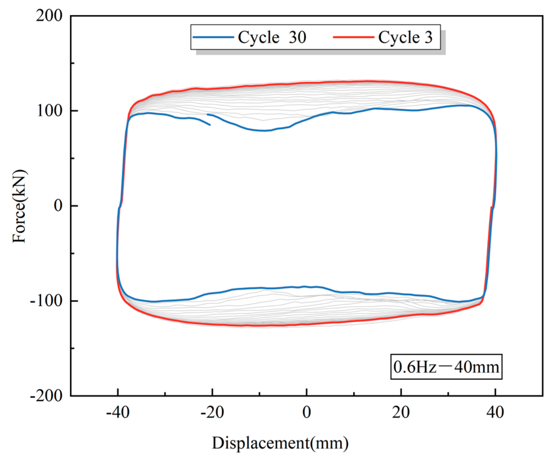
3.1. Experimental Results

The variation in the kinematic viscosity of viscous fluids is one of the direct causes of changes in the output of dampers. Factors that cause changes in the kinematic viscosity of viscous fluids primarily include dynamic viscosity, temperature, and pressure. Figure 4a,b present the hysteresis curves measured from specimens with different kinematic viscosities under the same loading conditions. To analyze the impact of changes in kinematic viscosity on performance, at a frequency of 0.1 Hz and with increasing displacement loads, the outputs of damper specimen #1 were 96 kN, 110 kN, 129 kN, 136 kN, 146 kN, and 150 kN; for damper specimen #2, the outputs were 51 kN, 64 kN, 81 kN, 88 kN, 96 kN, and 100 kN, respectively. Consistent with conventional understanding, the damper with lower kinematic viscosity exhibited lower damping forces. However, it is noteworthy that for specimens #1 and #2, under different loading displacements, not only did the output damping forces differ, but the deviations in damping force also varied, decreasing from 46.87% to 33.33% as the loading displacement increased. Given the known exponent and speed, it is likely that the damping coefficient has changed. Furthermore, it can be inferred that the kinematic viscosity of the damping fluid has altered due to changes in pressure and temperature, significantly affecting the mechanical performance of the dampers. The experimental results at 0.6 Hz, as shown in Figure 4c,d, exhibit a similar trend to those observed at 0.1 Hz.
Figure 5 compares the areas of the hysteresis curves at different loading displacements. When the frequency remains constant, changes in loading displacement imply variations in the shear speed of the piston against the damping fluid. In viscous fluid dampers, an increased shear speed enlarges the enclosed area of the force–displacement hysteresis loop, thereby enhancing the damper’s energy dissipation capacity. Taking specimen #1 as an example, a comparative analysis of cases 2, 5, and 7 shows that as the loading displacement increases from 5 mm to 60 mm, the damper output increases from 96 kN to 150 kN, representing a growth of 56.25%, while the energy dissipation increases by 17.75 times. The substantial increase in energy dissipation indicates that changes in shear speed can significantly affect the energy consumption of the damper. Specimen #2 exhibited a similar trend, with an even larger increase in energy dissipation, approaching 23 times. In gap-type viscous dampers, variations in the gap and the kinematic viscosity of the damping fluid can lead to changes in the shear rate.
Figure 6 shows the durability test results for the damper specimen 2. Following the initiation of the fatigue test, the internal temperature of the damper quickly escalated, with localized temperatures exceeding 200 degrees Celsius, leading to the discoloration of the oil cylinder; the pressure surged beyond 160 MPa. From the test curve, it is evident that the damper experienced significant force loss in later cycles, with the maximum damping force dropping from 131 kN to 105 kN, a decrease of 19.8%. During the fatigue testing process, the damping force decreased notably owing to the effects of high temperature and high pressure. The analysis indicates the following: (1) The damper cylinder undergoes slight deformation under high temperature and pressure, leading to changes in clearance. (2) Under high-temperature and high-pressure conditions, the damping fluid underwent degradation and performance deterioration.

3.2. Relationship of Temperature and Pressure

To further investigate the precise relationship between the temperature, pressure, and damper, an extensive experiment was conducted using a large-scale temperature chamber. The damper was uniformly heated at various temperatures within the chamber, and its internal pressure values were measured and systematically compiled, as listed in Table 3.
The numerical value of T1 reflects the temperature chamber. As this study primarily examined the influence of temperature increase on pressure, the actual temperature value of interest was obtained by subtracting the room temperature (25 °C) from the temperature set in the chamber, which corresponds to the value represented as Δ T . In Figure 7, the fitted curves for the pressure and Δ T are displayed, indicating that
Δ P Δ T = B l i p A l i p = 0.5521

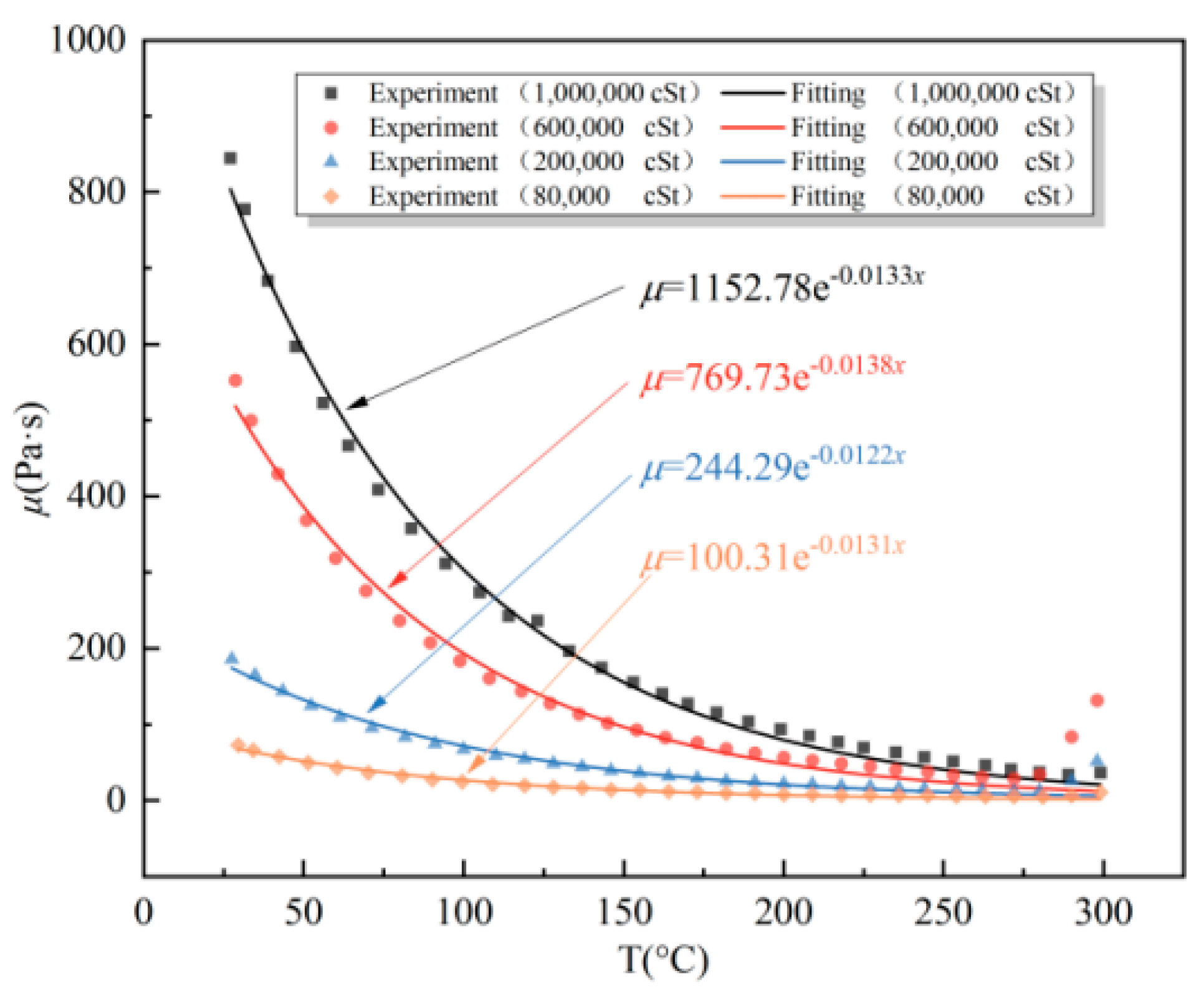
3.3. Effect of Kinematic Viscosity

Through viscometric temperature tests, the relationship between the dynamic viscosity and temperature under different kinematic viscosities was determined. The viscosity–temperature characteristics of the damping materials with various kinematic viscosities are depicted in Figure 8.
The experimental data were used to fit the dynamic viscosity–temperature relationship of the silicone oil used in this study using the exponential function μ = a e b x [22]. Table 4 summarizes the fitting results of Figure 8. From Table 4, it is evident that the exponential variation remains stable at approximately −0.013. Additionally, the coefficient ‘a’ of the exponential function increased as the kinematic viscosity increased. Figure 8 indicates that the dynamic viscosity of the silicone oil significantly depends on the temperature, particularly at lower temperatures. After reaching 200 °C, the dynamic viscosity reduction became more pronounced, indicating the potential degradation of the damping fluid. Therefore, particular attention should be paid to the damping fluid temperature when evaluating the energy dissipation of dampers under long-duration loads.
The data presented in Table 5 reveal that as the temperature increased from room temperature (25 °C) to 50 °C, 75 °C, 100 °C, 150 °C, and 200 °C, the dynamic viscosity decreased by approximately 35%, 55%, 65%, 80%, and 90%, respectively. With every 25 °C increase in temperature, the percentage decrease in dynamic viscosity was approximately 20%, 10%, 7.5%, and 5%, respectively. The data indicate that the dynamic viscosity of the silicone oil undergoes significant changes in the low-temperature range, but experiences increasingly smaller changes in the high-temperature range. These results were consistent with the trends shown in Figure 8.
Equation (2) represents the calculation formula for the viscosity–temperature coefficient [29]. In Equation (2), μ 98.9 denotes the kinematic viscosity at 98.9 degrees Celsius, measured in mm2/s2, and μ 37.8 represents the kinematic viscosity at 37.8 degrees Celsius, also in mm2/s2. Using Equation (1), the viscosity–temperature coefficients of viscous fluids under different kinematic viscosities can be determined, as shown in Table 6. It can be observed from Table 6 that higher kinematic viscosities lead to smaller changes in dynamic viscosity with temperature, thereby enhancing the fluid’s performance stability.
V T C = ( μ 37.8 μ 98.9 ) / μ 37.8 = 1 μ 98.9 / μ 37.8

4. Mathematical Model

4.1. Boundary Conditions

The boundary conditions between the outer surface of the damper cylinder and the air are particularly complex, typically involving heat conduction, convection, and radiation. In cases of forced conduction, the air surrounding the damper is assumed to maintain an almost constant temperature. Under these circumstances, convective boundary conditions are employed [16].
k s θ n = h ( T a i r T 0 ( t ) )
In Equation (3), h is the comprehensive heat transfer coefficient, which integrates the combined effects of convection, conduction, and radiation. k s θ n represents the radial heat flux, which, in the context of this study, can be approximated as k s θ n = k s ( T ( t ) T 0 ( t ) ) ε .

4.2. Theoretical Derivation

Equation (4) represents the temperature rise for each cycle under adiabatic conditions [19], where C is the damping coefficient, U 0 is the maximum displacement of the damper, and C p is the specific heat capacity under constant pressure. Traditionally, C is commonly regarded as a constant.
Δ T ( 2 π ω ) = π 2 Δ p max ρ C p = π C ω U 0 2 m C p = π 2 C ω U 0 ρ C p A
C = k π l ( D 2 d 2 ) 2 h 2 m + 1 [ ( 2 m + 1 ) ( D 2 d 2 ) ( D + D 0 ) m ] m
The internal pressure of the damper, as expressed in Equation (6), can be separated into two components: the pressure increase from the previous cycle P 1 and the pressure difference between the two sides of the piston in the current cycle P 2 . The overall pressure can be determined by solving for each component individually.
P = P 1 + P 2 = N B l i p A l i p Δ T + | 4 C ( U 0 sin ω t ) α π ( D 2 d 2 ) |
Based on the dynamic viscosity–temperature and dynamic viscosity–pressure characteristics, the combined influence of oil dynamic viscosity and temperature [29] and the pressure variation [11,13,30] can be represented by Equation (7), where T 0 is the initial temperature, T is the temperature following the temperature rise, u 0 stands for the dynamic viscosity at T 0 , λ referred to as the dynamic viscosity–temperature coefficient, α represents the dynamic viscosity–pressure coefficient, and p signifies the fluid pressure.
μ = μ 0 e α p λ ( T T 0 )
In the above equations, both the pressure variable p and temperature variable t exist, which makes the treatment of practical problems inconvenient. The flow of liquid through clearances involves not only a pressure drop but also heat generation. The pressure drop and temperature rise occur simultaneously within a unified system, and their relationship can be analyzed from an energy perspective.
The energy relationship when oil flows through the clearance per unit time is as follows: (1) The pressure drop (dp) across the flow results in a loss of energy q·dp, where q represents the liquid flow rate. (2) A part of the energy is lost because of the liquid friction caused by the viscosity during the flow. (3) The losses of these two types of energy are converted into heat energy, leading to an increase in the oil temperature. The heat gained by the oil is given by q·ρ·c·dT, where ρ is the mass density of the liquid and c is the specific heat capacity of the liquid. (4) Another portion of the heat energy is dissipated into the surrounding environment through the cylinder wall.
q d p = ρ q c d T
Overall, considering only the pressure-differential flow, the energy dissipated into the surrounding environment was much smaller than the heat generated by the temperature increase. Therefore, it can be assumed that the heat dissipation is balanced by E2, and all energy from the pressure drop is used to increase the oil temperature. Let q represent the liquid flow rate and P1 and T1 represent the oil pressure and temperature at the gap inlet, respectively. Assuming that the oil pressure and temperature at distance x from the inlet are denoted as P and T, respectively, we can observe a pressure drop of (P1P) and a temperature rise of TT1 within this length x.
Thus
q ( P 1 P ) = ρ q c ( T T 1 )
After simplification
T T 1 = P 1 P ρ c = Φ ( P 1 P ) Φ = 1 ρ c
Therefore
μ = μ 0 e α P λ Φ ( P 1 P ) = μ 0 e α P + λ Φ ( P P 1 )
As a result
μ = μ 1 e ( P P 1 ) / P t
where μ 1 represents the dynamic viscosity of the fluid when P = P 1 and T = T 1 ; μ 0 represent the dynamic viscosity of the fluid when P = P 0 and T = T 1 ; and P t denotes the thermodynamic pressure, which remains constant for a fixed fluid p t = 1 α + λ Φ .
Substituting Equation (12), and simplifying, we get
μ = μ 1 e ( T T 1 ) α + λ Φ Φ = μ 1 e ( T T 1 ) ( α Φ + λ ) = μ 1 e Δ T ( α Φ + λ )
Equation (13) enables the computation of the dynamic viscosity of the damping fluid after each temperature increase cycle under long-duration loads.
The changes in temperature and pressure not only significantly influence the dynamic viscosity of the damping fluid, but also induce deformation in the damper cylinder, resulting in an enlargement of the damper gap. The radial deformation caused by pressure during damper operation is also a significant factor to consider.
Δ D = P D E ( D 1 2 + D 2 D 1 2 D 2 + υ )
In Equation (14), P represents the operating pressure of the damper, D is the inner diameter, D 1 is the outer diameter, E denotes the elastic modulus of the damper material, and υ is Poisson’s ratio of the damper material.
The relationship between the temperature and pressure can be approximated as linear. By substituting Equation (1) into Equation (14), the radial deformation of the damper can be determined as
Δ D = D E ( D 1 2 + D 2 D 1 2 D 2 + υ ) · B l i p A l i p Δ T
By Equation (15), the radial deformation quantity of the damper sleeve after the next cycle of temperature rise can be calculated.
Damper   Clearance :   h 1 = h + Δ D / 2
Equation (4) reflects the temperature increase in the damper after a cycle. In Equation (4), parameter C is considered constant. However, owing to the influence of the temperature and pressure rise on the dynamic viscosity of the damper fluid, as well as the deformation of the cylinder caused by the temperature and pressure rise, the damping coefficient C experiences slight variations for each cycle. As a result, the temperature increase for each cycle decreased slightly, and the outcome was dependent only on the damping coefficient C. By substituting Equations (13), (15) and (16) into the damping coefficient calculation formula in Equation (4), the ratio of the temperature increase between two consecutive cycles is given by Equation (17). Through iterative summation, the temperature increase after 30 cycles could be determined, allowing for the calculation of the increase in pressure, as follows:
Δ T 1 Δ T 2 = C 1 C 2 = k 1 h 2 2 m + 1 k 2 h 1 2 m + 1
Dynamic viscosity μ can be obtained through Equation (13), and subsequently, the consistency coefficient k can be determined. By employing Equation (16), the gap h is computed. And then, based on Equation (17), the temperature rise Δ T for each cycle can be determined. Finally, Equation (6) yields pressure results, and through an iterative approach, the corrected theoretical pressure values are obtained. This method is of paramount importance in evaluating the mechanical performance of dampers.

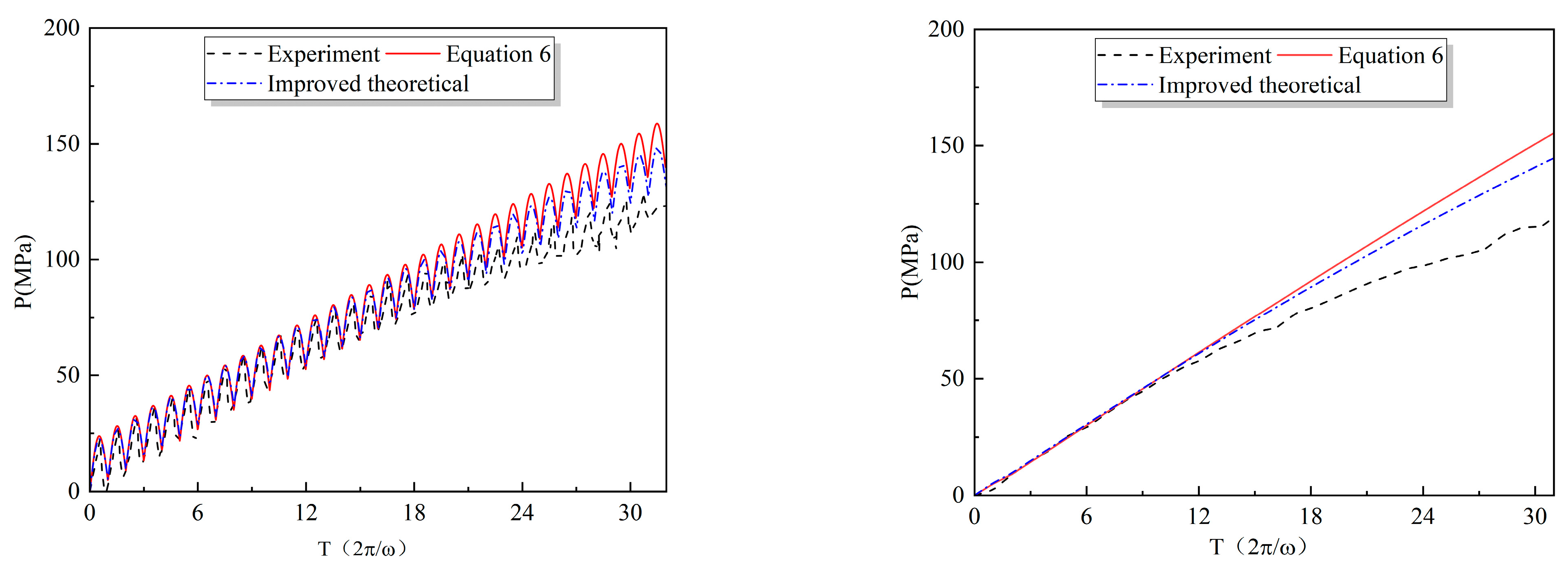
5. Comparison of Numerical and Experimental Results

Through iterative summation, the temperature increase after 30 cycles could be calculated, which in turn allowed us to determine the extent of the pressure increase. The fitting result for the dynamic viscosity–temperature relationship of the 80,000 cSt silicone oil is μ = 100 . 31 e 0.0131 x . The shear–strain rate for the dynamic viscosity–temperature variable temperature test of the silicone oil is γ . = 0.05 s 1 . The consistency coefficient can be determined through the following calculation [14], k = μ γ m 1 . = μ 0.05 0.24 1 = μ 10.04 .
Referring to Table 1 for the damper’s structural parameters, the ratio of the temperature rise between the initial and final cycles can be calculated for the fatigue condition at 0.6 Hz–40 mm, taking into account the coupling effects of temperature, pressure, viscosity, and deformation: Δ T 1 Δ T 2 = C 1 C 2 = k 1 h 2 2 m + 1 k 2 h 1 2 m + 1 = 0.989 .
Hence, the temperature increase during the second cycle is Δ T 2 ( 2 π ω ) = 8.51 × 0.989 = 8.425   ° C .
The relationship between the temperature and pressure, denoted as Δ P Δ T = 0.5521 , was iterated to calculate the pressure increment for each cycle, allowing us to determine the pressure increase after 30 cycles. The detailed results are presented in Table 7.
After performing the iteration, the pressure increase for 30 fatigue cycles was determined to be Δ P 30 cycle = 123.63   MPa .
In the mechanical performance tests, real-time pressure variations were obtained using hydraulic gauges mounted on the cylinder. The pressure–time history recorded during the tests is depicted in Figure 9. The pressure data were collected via external hydraulic gauges attached to the walls of the damper cylinder, which may introduce some measurement errors in accurately reflecting the internal pressure of the damper cylinder, and the actual internal pressure of the damper cylinder may be slightly higher than the experimental values obtained.
As shown in Figure 9, Equation (6) represents the internal pressure, considering the effects of temperature and pressure. This provides improved theoretical accounts for the coupled effects of the temperature, pressure, viscosity of the damping fluid, and the deformation of the damping cylinder.
In Figure 9, the temperature and pressure in the last 15 cycles significantly improved the alignment between the theoretical and experimental values. The discrepancy between the theoretical and experimental pressure values after the 30-cycle fatigue test was 8.42%, indicating a reasonable level of accuracy for the theoretical analysis.

6. Conclusions

This study provided an improved mechanical model, considering the coupling effects of temperature and pressure, which was proposed to accurately characterize the dynamic mechanical behavior of VFD under long-duration loads. The main findings are summarized as follows:
The working process of the VFD leads to a pressure difference between the two sides of the cylinder, whereas temperature elevation causes an increase in the internal pressure on both sides of the piston. Temperature has a significant impact on internal pressure, with high temperatures and pressures exerting a more pronounced effect on the performance of low-viscosity damping fluids.
By fitting the experimental data of the viscosity–temperature characteristics of the silicone oil, the relationship between the dynamic viscosity and temperature was established. The effects of temperature and pressure on the dynamic viscosity of the damping fluid were considered. Considering the correlation between damper deformation and working pressure, a mechanical model of the viscous damper was established by considering the overall macroscopic energy balance of the fluid and combining the constitutive equation of the pore–viscous fluid damper. The numerical value of the pressure increments under 30 fatigue cycles under the coupling effects was obtained with an error of only 8.42% compared with the theoretical and experimental results, thus improving the accuracy and reliability of the findings.

Author Contributions

Methodology, W.X. and D.D.; Validation, W.X.; Resources, S.W.; Data curation, Y.G.; Writing—original draft, Y.Z.; Writing—review & editing, S.W. and D.D. All authors have read and agreed to the published version of the manuscript.

Funding

The author(s) disclosed the receipt of the following financial support for the research, authorship, and/or publication of this article: the authors acknowledge financial support from the National Natural Science Foundation of China [grant number 52208173, 52008413], the Major Basic Research Project of the Natural Science Foundation of the Jiangsu Higher Education Institutions [grant number 22KJA560003], Major R&D projects of MCC Group YCC2021Kt01 Safety and Quality Improvement and Application of Building and Environment in Urban Renewal [grant numbers YCC2021Kt01], and the fellowship of China Postdoctoral Science Foundation [grant numbers 2022M721591].

Data Availability Statement

Data are contained within the article.

Conflicts of Interest

Author Yan Geng was employed by the company MCC Group, Central Research Institute of Building and Construction Co., Ltd. The remaining authors declare that the research was conducted in the absence of any commercial or financial relationships that could be construed as a potential conflict of interest.

References

  1. Ngatu, G.T.; Wereley, N.M.; Kothera, C.S. Hydromechanical analysis of a fluid-elastomeric lag damper incorporating temperature effects. J. Aircraft. 2012, 49, 1212–1221. [Google Scholar] [CrossRef]
  2. Martínez-Rodrigo, M.D.; Filiatrault, A. A case study on the application of passive control and seismic isolation techniques to cable-stayed bridges: A comparative investigation through non-linear dynamic analyses. Eng. Struct. 2015, 99, 232–252. [Google Scholar] [CrossRef]
  3. Wang, J.; Zhao, S.; Wu, D.; Jing, X. The interior working mechanism and temperature characteristics of a fluid based micro-vibration isolator. J. Sound Vibr. 2016, 360, 1–16. [Google Scholar] [CrossRef]
  4. Buclny, D.D.; Wiggert, D.C.; Hatfield, F.J. The influence of structural damping on internal-pressure during a transient pipe-flow. J. Fluids Eng.-Trans. ASME 1991, 113, 424–429. [Google Scholar]
  5. He, X.; Wu, T.; Wang, Y. Modeling and characteristics of viscous damper using throttled fluid mixed with air. J. Vib. Shock 2014, 33, 95–100. [Google Scholar]
  6. Kitayama, S.; Constantinou, M.C. Fluidic self-centering devices as elements of seismically resistant structures description, testing, modeling, and model validation. J. Struct. Eng. 2017, 143, 04017050. [Google Scholar] [CrossRef]
  7. Liang, G.; Zhao, T.; Li, N.; Wei, Y.; Savaresi, S.M. Magnetorheological damper temperature characteristics and control-oriented temperature-revised model. Smart Mater. Struct. 2021, 30, 125005. [Google Scholar] [CrossRef]
  8. Xu, W.; Du, D.; Kasai, K.; Wang, S. Optimization layout of viscous dampers and its application in retrofitting of a high-rise steel structure. J. Build. Struc. 2022, 43, 32–44. [Google Scholar]
  9. Xu, W.; Wang, Y.; Guo, H.; Du, D.; Wang, S. Theoretical and experimental investigation on the seismic performance of a novel variable-damping viscous fluid damper. J. Build. Eng. 2022, 53, 104537. [Google Scholar] [CrossRef]
  10. Makris, N.; Constantinou, M.C. Fractional-derivative maxwell model for viscous dampers. J. Struct. Eng. 1991, 117, 2708–2724. [Google Scholar] [CrossRef]
  11. Makris, N.; Constantinou, M.C.; Dargush, G.F. Analytical model of viscoelastic fluid dampers. J. Struct. Eng. 1993, 119, 3310–3325. [Google Scholar] [CrossRef]
  12. Yu, Q.; Xu, D.; Zhu, Y.; Guan, G.; Li, Q. Damping characteristic modeling and numerical simulation analysis of the viscous damper of a clearance hydrocylinder. J. Vib. Shock 2020, 39, 161–167. [Google Scholar]
  13. Constantinou, M.C.; Symans, M.D. Experimental & Analytical Investigation of Seismic Response of Structures with Supplemental Fluid Viscous Dampers. 1992. Available online: https://www.buffalo.edu/mceer/catalog.host.html/content/shared/www/mceer/publications/NCEER-92-0032.detail.html (accessed on 21 May 2024).
  14. Ou, J.; Ding, J. Theory and performance experiment of viscous damper of clearance hydrocylinder. Earthq. Eng. Eng. Vib. 1999, 19, 82–89. [Google Scholar]
  15. Ding, J.; Ou, J. Theoretical study and performance experiment for cylinder-with-holes viscous damper. World Earthq. Eng. 2001, 17, 30–35. [Google Scholar]
  16. Black, C.J.; Makris, N. Viscous heating of fluid dampers experimental studies. In Proceedings of the SPIE’s 7th Annual International Symposium on Smart Structures and Materials, Newport Beach, CA, USA, 5–9 March 2000. [Google Scholar]
  17. Black, C.J.; Makris, N. Viscous heating of fluid dampers under small and large amplitude motions: Experimental studies and parametric modeling. J. Eng. Mech. 2007, 133. [Google Scholar] [CrossRef]
  18. Hou, C.Y. Fluid dynamics and behavior of nonlinear viscous fluid dampers. J. Struct. Eng. 2008, 134, 56–63. [Google Scholar] [CrossRef]
  19. Makris, N. Viscous heating of fluid dampers. I: Small-amplitude motions. J. Eng. Mech. 1998, 124, 1210–1216. [Google Scholar] [CrossRef]
  20. Makris, N.; Roussos, Y.; Whittaker, A.S.; Kelly, J.M. Viscous heating of fluid dampers. II: Large-amplitude motions. J. Eng. Mech. 1998, 124, 1217–1223. [Google Scholar] [CrossRef]
  21. He, L.; Zheng, G. Feedback effect of viscous heating and heat balance of fluid damper. Chin. J. Appl. Mech. 2006, 505–510+691. [Google Scholar]
  22. He, L.; Yang, Q.; Zheng, G. Effect of viscous heating of the fluid damper on the whole-spacecraft vibration isolation. Chin. J. Mech. Eng. 2007, 43, 31–64. [Google Scholar] [CrossRef]
  23. He, L.; Yang, Q.; Zheng, G. Effect of temperature of fluid isolator on whole-spacecraft vibration isolation. Aerosp. Shanghai 2008, 44–47+57. [Google Scholar] [CrossRef]
  24. Amangeldi, M.; Wang, Y.; Perveen, A.; Zhang, D.; Wei, D. An iterative approach for the parameter estimation of shear-rate and temperature-dependent rheological models for polymeric liquids. Polymers 2021, 13, 4185. [Google Scholar] [CrossRef] [PubMed]
  25. Chmielowiec, A.; Wo’s, W.; Gumieniak, J. Viscosity approximation of PDMS using Weibull function. Materials 2021, 14, 6060. [Google Scholar] [CrossRef] [PubMed]
  26. Venczel, M.; Bognár, G.; Veress, Á. Temperature-dependent viscosity model for silicone oil and its application in viscous dampers. Processes 2021, 9, 331. [Google Scholar] [CrossRef]
  27. Lak, H.; Zahrai, S.M. Self-heating of viscous dampers under short- & long-duration loads: Experimental observations and numerical simulations. Structures 2023, 48, 275–287. [Google Scholar]
  28. Du, D.; Song, B.; Xu, W. Seismic retrofit of a high-rise steel structure considering long-period and long-duration ground motions. J. Eng. Mech. 2020, 37, 189–200. [Google Scholar]
  29. Deng, J.; Fang, Y.; Qin, H.; Xu, F. The filling material viscidity characteristic of helicopter fluidlastic damper. Helicopter Tech. 2007, 2, 7–11. [Google Scholar]
  30. Makris, N.; Dargush, G.F.; Constantinou, M.C. Dynamic Analysis of Generalized Viscoelastic Fluids. J. Eng. Mach. 1993, 119, 1663–1679. [Google Scholar] [CrossRef]
Figure 1. Schematic diagram and components of the viscous fluid damper specimen.
Machines 12 00366 g001
Figure 2. Test setup.
Machines 12 00366 g002
Figure 3. Viscous fluid and test equipment.
Machines 12 00366 g003
Figure 4. Hysteresis curve at low frequency.
Machines 12 00366 g004aMachines 12 00366 g004b
Figure 5. Force–displacement curve.
Machines 12 00366 g005
Figure 6. The 2# specimen durability test hysteresis curve.
Machines 12 00366 g006
Figure 7. Temperature–pressure curve.
Machines 12 00366 g007
Figure 8. Relationship between dynamic viscosity and temperature of damping liquid with varying kinematic viscosities.
Machines 12 00366 g008
Figure 9. Pressure periodic curve (experimental and theoretical comparison).
Machines 12 00366 g009
Table 1. Test sample characteristics.
SpecimenL/mmD/mmd/mmGap
/mm
D0/mmSilicone Fluid
1#5080300.3079.40600,000 cSt
2#5080300.3079.4080,000 cSt
Table 2. Loading scheme.
Test CaseCaseFrequency (Hz)Displacement (mm)Number of CyclesMaximum Velocity (m/s)
Ultimate displacement10.017520.00
Low frequency 20.1550.00
3100.01
4250.02
5350.02
6500.03
7600.04
Medium frequency 80.6550.02
9100.04
10250.09
11350.13
12450.17
Durability performance130.640300.15
Table 3. Temperature–pressure relationship (room temperature: 25 °C).
T1 (°C)253035404550607080
Pressure (MPa)3810121520242934
ΔT0510152025354555
Table 4. Curve fitting parameter table for viscosity–temperature relationship of silicone oil.
ParameterViscosity
1,000,000 cSt600,000 cSt200,000 cSt80,000 cSt
a1152.78769.73244.29100.31
b−0.0133−0.0138−0.0122−0.0131
Table 5. Viscosity–temperature change in silicone oil viscosity.
TemperatureViscosity (Rate of Change)
1,000,000 cSt600,000 cSt200,000 cSt80,000 cSt
25 °C85056520080
50 °C560 (34.12%)369 (34.69%)130 (35.00%)50 (37.50%)
75 °C390 (54.12%)256 (54.69%)90 (55.00%)34.6 (56.75%)
100 °C293 (65.53%)182 (67.79%)67.5 (66.25%)25 (68.75%)
150 °C160 (81.18%)97 (82.83%)38 (81.00%)14.3 (82.13%)
200 °C94 (88.94%)57 (89.91%)22.4 (88.80%)8 (90.00%)
Table 6. Silicone oil viscosity–temperature coefficient.
Viscosity1,000,000 cSt600,000 cSt200,000 cSt80,000 cSt
Viscosity–temperature coefficient0.5720.5750.5780.596
Table 7. Results of pressure iteration.
CycleTemperature RatioΔTΔPCycleTemperature RatioΔTΔP
10.9908.5104.698160.9917.3874.079
20.9908.4254.651170.9917.3234.043
30.9908.3414.605180.9917.2604.008
40.9908.2594.560190.9927.1983.974
50.9908.1794.515200.9927.1363.940
60.9908.1004.472210.9927.0763.907
70.9918.0224.429220.9927.0173.874
80.9917.9464.387230.9926.9593.842
90.9917.8724.346240.9926.9023.811
100.9917.7994.306250.9926.8463.780
110.9917.7274.266260.9926.7903.749
120.9917.6574.227270.9926.7363.719
130.9917.5884.189280.9926.6833.689
140.9917.5204.152290.9926.6303.660
150.9917.4534.115300.9926.5783.632
Disclaimer/Publisher’s Note: The statements, opinions and data contained in all publications are solely those of the individual author(s) and contributor(s) and not of MDPI and/or the editor(s). MDPI and/or the editor(s) disclaim responsibility for any injury to people or property resulting from any ideas, methods, instructions or products referred to in the content.

