Article

The Design of Decoupled Robotic Arm Based on Chain Transmission

School of Mechanical Engineering, North China University of Water Resources and Electric Power, Zhengzhou 450045, China
*
Author to whom correspondence should be addressed.
Machines 2024, 12(6), 410; https://doi.org/10.3390/machines12060410
Submission received: 14 May 2024 / Revised: 13 June 2024 / Accepted: 14 June 2024 / Published: 15 June 2024
(This article belongs to the Section Machine Design and Theory)

Abstract

:
Unlike the conventional robotic arm where the joints are coupled to each other, this paper proposes a position and posture decoupling method to mechanically correct the end position of the robotic arm in real time through dual-motion transmission, which is both motor-reducer-driven and chain-driven; when the position of the end of the robotic arm changes, the positional linkage of each articulated arm end is unaffected. First, a single-section chain-driven decoupled robotic arm is constructed, and then the design of a two-degrees-of-freedom chain-driven decoupled robotic arm system is completed based on a single arm. Second, kinematic analysis of the decoupled robotic arm system is performed to obtain its trajectory and workspace. Moreover, an analysis of the transmission mechanism engagement clearance error is carried out. Finally, a mini-experimental prototype is built, and the rationality of the decoupled robotic arm system is proven by experiments. The experimental results show that the robotic arm is generally able to realize positional decoupling stably during movement, providing certain theoretical support and practical experience for the design requirements of related robotic arms.

1. Introduction

With the rapid development of automation, as an important part of modern industrial production, industrial robots have been widely used in automated production lines in dozens of industries, such as mechanical processing, automotive industry, mold manufacturing and so on [1,2,3,4,5].
Currently, most production lines utilize multiple-degrees-of-freedom rigid serial robots to accomplish the corresponding machining requirements. The technology of these robotic arms is mature; however, these robotic arms disperse drive components such as motors and gearboxes to each joint, which results in heavy robot weight, large rotational inertia, and low load-carrying capacity. In addition, there is kinematic coupling between the articulated robotic arms, which makes it difficult to ensure stability and accuracy in large-scale spatial (e.g., planar spraying, chiseling, etc.) applications [6,7,8,9,10,11,12].
In recent years, the concept of decoupled robotic arms has been proposed. In a decoupled robotic arm, the joints of the robotic arm are uncoupled, which makes the end-effector work with higher precision and stability compared with the traditional robotic arm. In addition, the decoupled robotic arm joints have no effect on each other, which also greatly simplifies motion planning and control algorithms.
The current research idea of a decoupled robotic arm is roughly divided into two kinds: control decoupling and mechanical decoupling. Control decoupling mostly utilizes sensors for real-time monitoring and error compensation through control algorithms. Lu Q. et al. proposed an end-to-end inclination state monitoring method for the robotic drilling process, which achieved the detection of drilling inclination with the help of machine vision and sensors, and effectively reduced the drilling error of the robotic arm [13]. Qian J. et al. proposed a static deformation compensation method for a large mechanical arm based on the feedback of an inclination sensor and applied it to a mobile concrete pump robot; the validity of the static deformation compensation method was verified by a comparison between the theoretical end position after compensation and the actual end position [14]. The above proposals are control decoupled, with the help of sensor feedback and corrected by algorithms. Although the decoupling function can be realized, the algorithm is complex, the calculation workload is large, and there are significant technical requirements for operators.
Liu X.J. et al. proposed a two-degrees-of-freedom parallelogram spraying robotic arm. Utilizing properties of the parallelogram, the robot arm can maintain a stable and unchanged position during the spraying process, which realizes the motion decoupling of the robotic arm in a mechanical structure form. However, this approach is limited by the parallelogram structure, which restricts the space available for the movement of each arm section; particularly, the motion space of each robot arm ranges from 20° to 160° [15].
Based on the above consideration, this paper proposes a position decoupling method for mechanically correcting the end position of a robotic arm in real time through dual-motion transmission. The dual motion refers to the rotational motion of the spindle driven by a motor-reducer and the follow-up motion of the transmission mechanism. Subsequently, the end position of the robotic arm is corrected in real time through the synchronization of the two motions. With its advantages of a large load capacity, accurate transmission and high efficiency [16,17,18,19,20], chain-driven transmission is used as the transmission mechanism in this design. Motion decoupling of the robotic arm is realized in the form of a mechanical structure by combination with the chain-driven transmission and motor-reducer.
In comparison with current decoupling studies, chain-driven decoupled robotic arms have the following advantages:
(1) The chain-driven decoupled robotic arm adopts the research idea of mechanical decoupling, and can maintain end-position decoupling in its pure mechanical structure. Compared to control decoupling, the number of motors, sensors and related electronic control devices used is fewer, which can greatly reduce manufacturing costs. Meanwhile, the reduction in related algorithms has also reduced the workload and technical requirements for the workers.
(2) In chain-driven decoupled robotic arm systems, each arm has a motion range of 0–180°. In comparison to the parallelogram mechanism, which is also mechanically decoupled, the chain-driven decoupled robotic arm has a larger workspace.
The structural design of the chain-driven decoupled robotic arm system is described in Section 2. The kinematic analysis of this decoupled robotic arm system is explained in Section 3. The potential engagement clearance error analysis of the transmission mechanism of the decoupling robotic arm system is provided in Section 4. The mini-experimental prototype is built for decoupling performance test experiments in Section 5. Finally, the conclusions and future work are presented in Section 6.

2. Materials and Methods

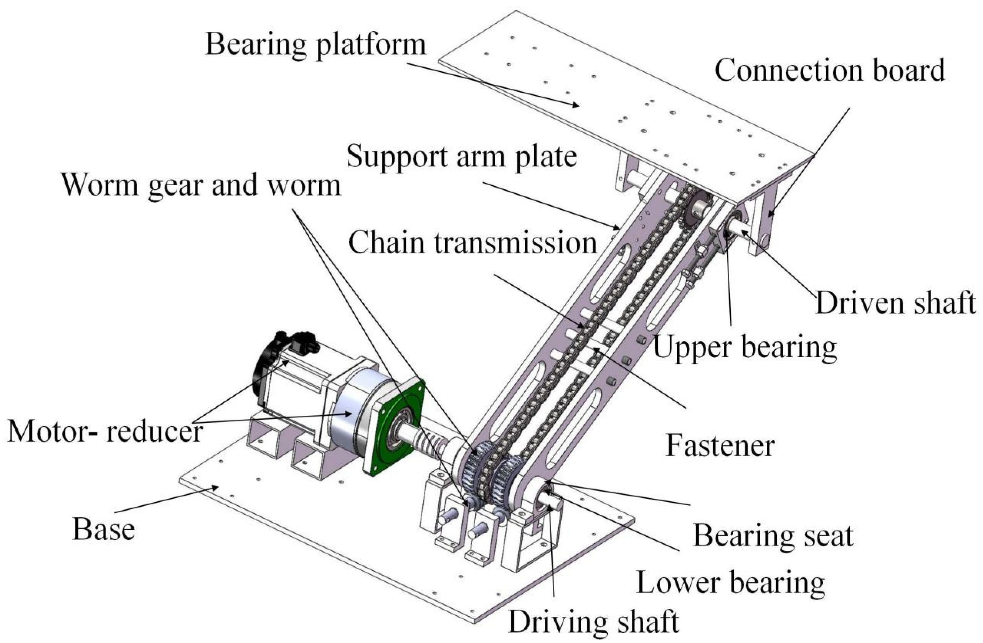
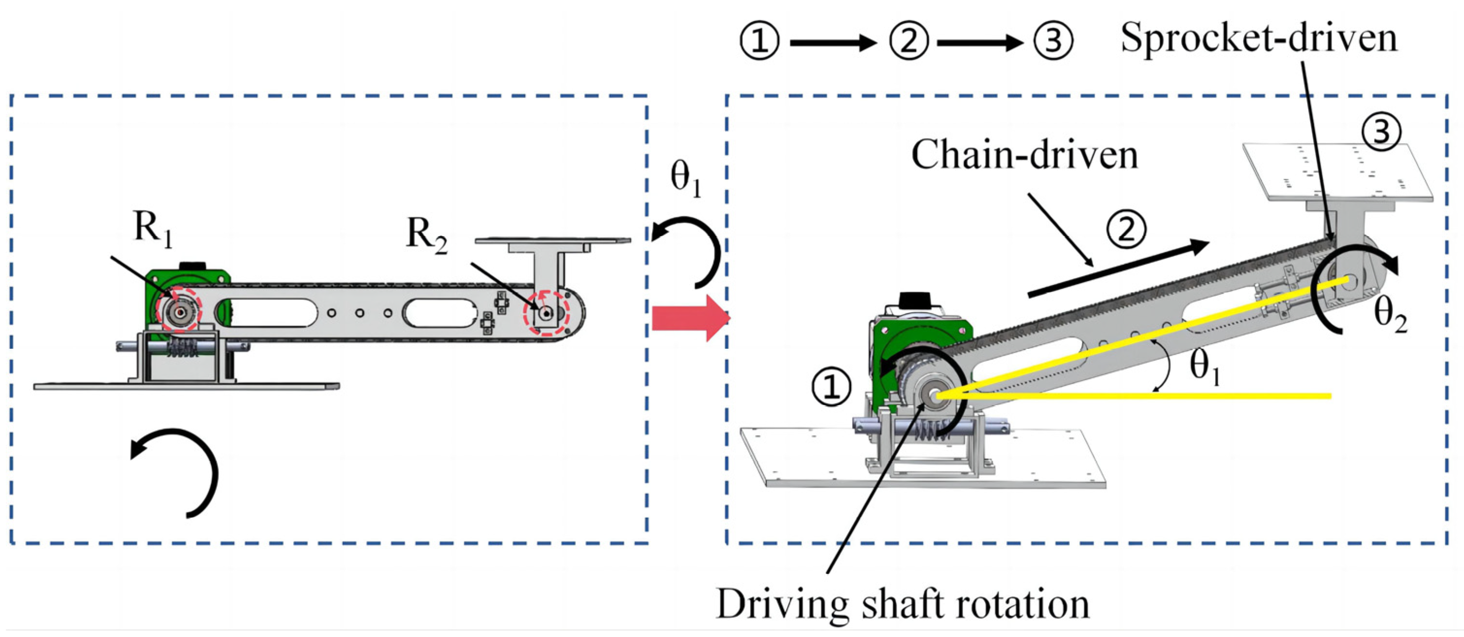
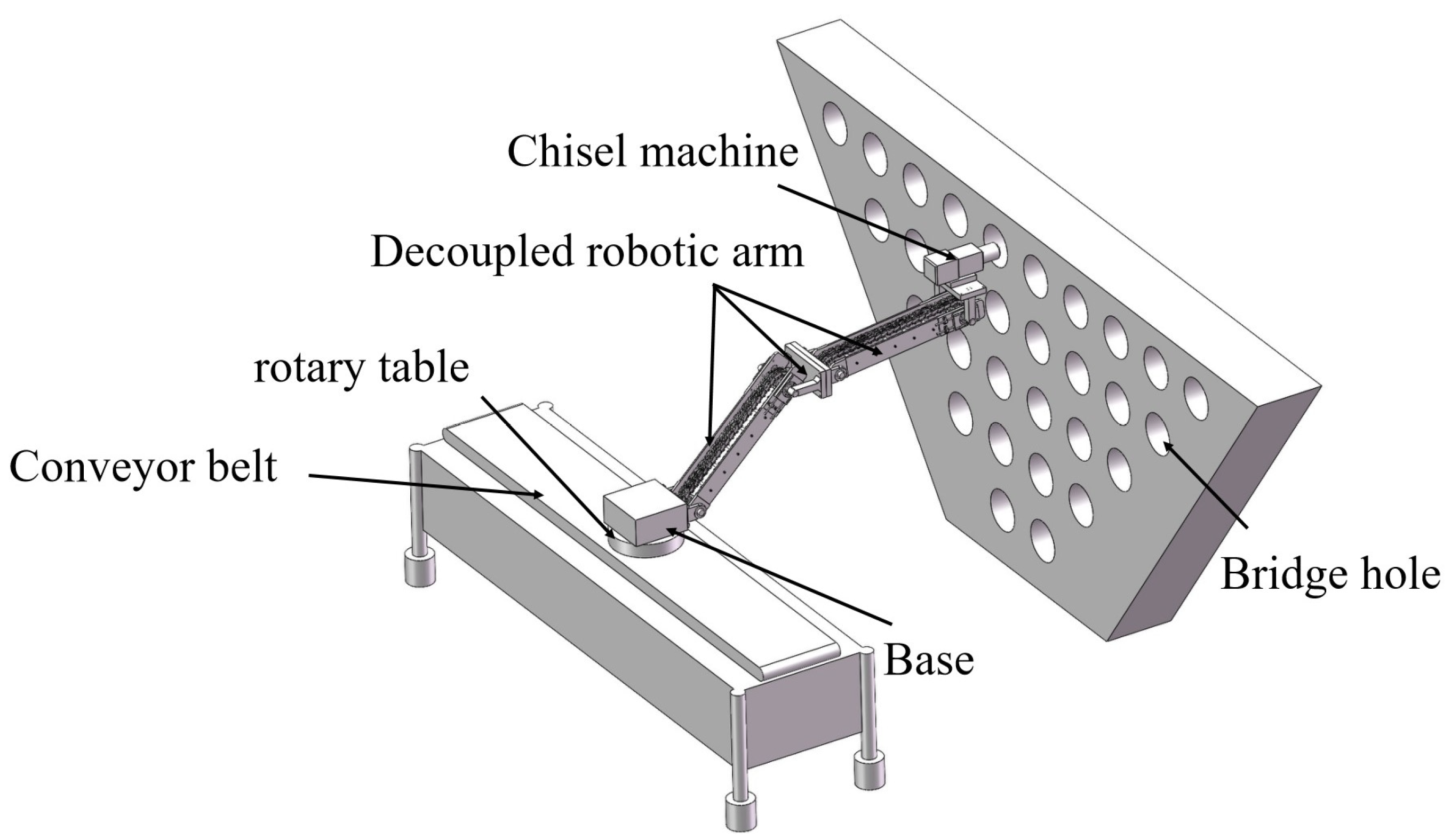
2.1. Chain-Driven Decoupled Robotic Arm System Structure Design

The structure of a single-section chain-driven decoupled robotic arm is shown in Figure 1. It comprises a base that is permanently secured upward with a pair of bearing seats. The bearing seats are equipped with lower bearings, and the lower bearings of the bearing seats are rotationally connected to a driving shaft. Moreover, the driving shaft extends out of the bearing seat and is connected to the external motor-reducer combination. The motor-reducer combination is used to drive the driving shaft to rotate. The working speed of the robotic arm is low.
The driving shaft is firmly attached to two support arm plates, and the support arm plates are connected with fasteners to ensure the overall structural strength. Then, the top of the support arm plates is connected with the driven shaft through the upper bearing, and the driven shaft is fixed to a connection board. In addition, the end of the connection board is firmly attached to the bearing platform, and the chain transmission mechanism is connected between the driving shaft and the driven shaft. Furthermore, the lower sprocket is concentric with the driving shaft but not permanently secured, whereas the upper sprocket is firmly connected to the driven shaft. The chain transmission mechanism is located in the space between the two support arm plates. At the same time, conventional end tensioning is used at the end of the support arm plate, which keeps the chain under tension at all times and ensures smooth movement. To ensure the safety of the robotic arm, the servo motor needs to be installed with a brake function to prevent the arm from falling due to malfunction or power failure. Meanwhile, the chain drive mechanism is regularly lubricated and tensioned to prolong its useful life.
The principle of dual motion transfer is shown in Figure 2. When the motor-reducer starts, the driving shaft drives the support arm plate to rotate (Figure 2①). At this time, the lower sprocket is locked and stationary, and the chain begins to wind on the lower sprocket (Figure 2②). Because of the relationship between the chain and the sprocket, the chain drives the upper sprocket to rotate in the opposite direction (Figure 2③), which causes the driven shaft to rotate in the opposite direction. Then, the dual-motion transmission equation is solved as follows:
θ 1 × R 1 = θ 2 × R 2
When the number of teeth and radius are the same in the upper and lower sprockets of the robotic arm and the chain is under tension, the rotation angle of the driving shaft relative to the lower sprocket is equal to the rotation angle of the chain wrapped around the lower sprocket. At the same time, the chain drives the upper sprocket to rotate at the same angle in the opposite direction. The angle of the upper sprocket’s reverse rotation is also the angle of the driven shaft’s reversal, and the angle of the driven shaft’s reversal just offsets the angle of the driven shaft’s rotation following the support arm plate, which prevents the drive shaft from rotating relative to the base. Therefore, in the whole movement process, the platform on the chain-driven shaft is only changed in the spatial position relative to the base, and its own posture relative to the base remains unchanged.
According to this characteristic, as long as the position of the end platform is determined initially, the position of the end platform can be unchanged with the movement of the robotic arm. At this time, the robotic arm is equivalent to a decoupled device without the end-effector. Therefore, as long as the load capacity of the robot arm end platform is greater than the weight of the actuator, the actuator (e.g., drill, welding torch, etc.) can be fixedly connected to the end platform. And then the robot arm is rotated by controlling the servo motor. Finally, the actuator is sent to the working area by the robotic arm to complete the machining operation.
Currently, the working space of a single arm is usually limited. To enhance the working space of the robotic arm, the robotic arm was extended on the basis of one arm in this study. We built a two-degrees-of-freedom decoupled robotic arm system using two identical robotic arms for head-to-tail connection, and then added an end-effector to the end platform of the second robotic arm. For example, we simulate the use of the robotic arm in Figure 3. First, we prepared a mini-experimental prototype, and then we regarded the electric drill as the end-effector and fixed the electric drill on the end platform with a sticky board. Finally, the servo motor position mode was used to control the robotic arm rotation, and then an electric drill was sent to the wall to drill the wall surface.
In contrast to the joint coupling of the end position of the conventional multi-jointed robotic arm during operation (shown in Figure 4), the chain-driven decoupled robotic arm in Figure 3 enables the electric drill to realize the decoupling of the position during the movement process.

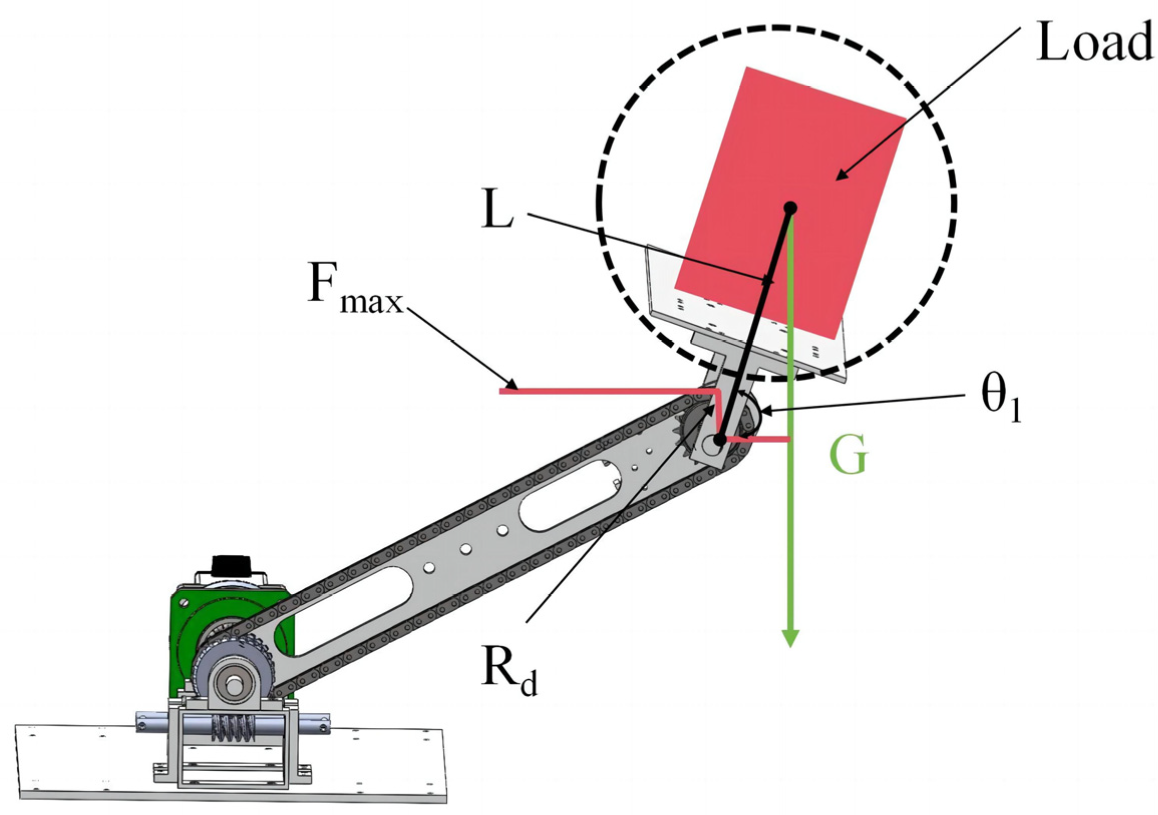
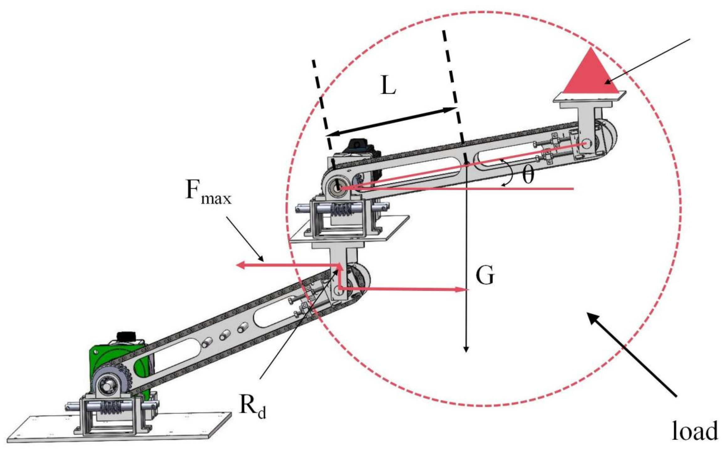
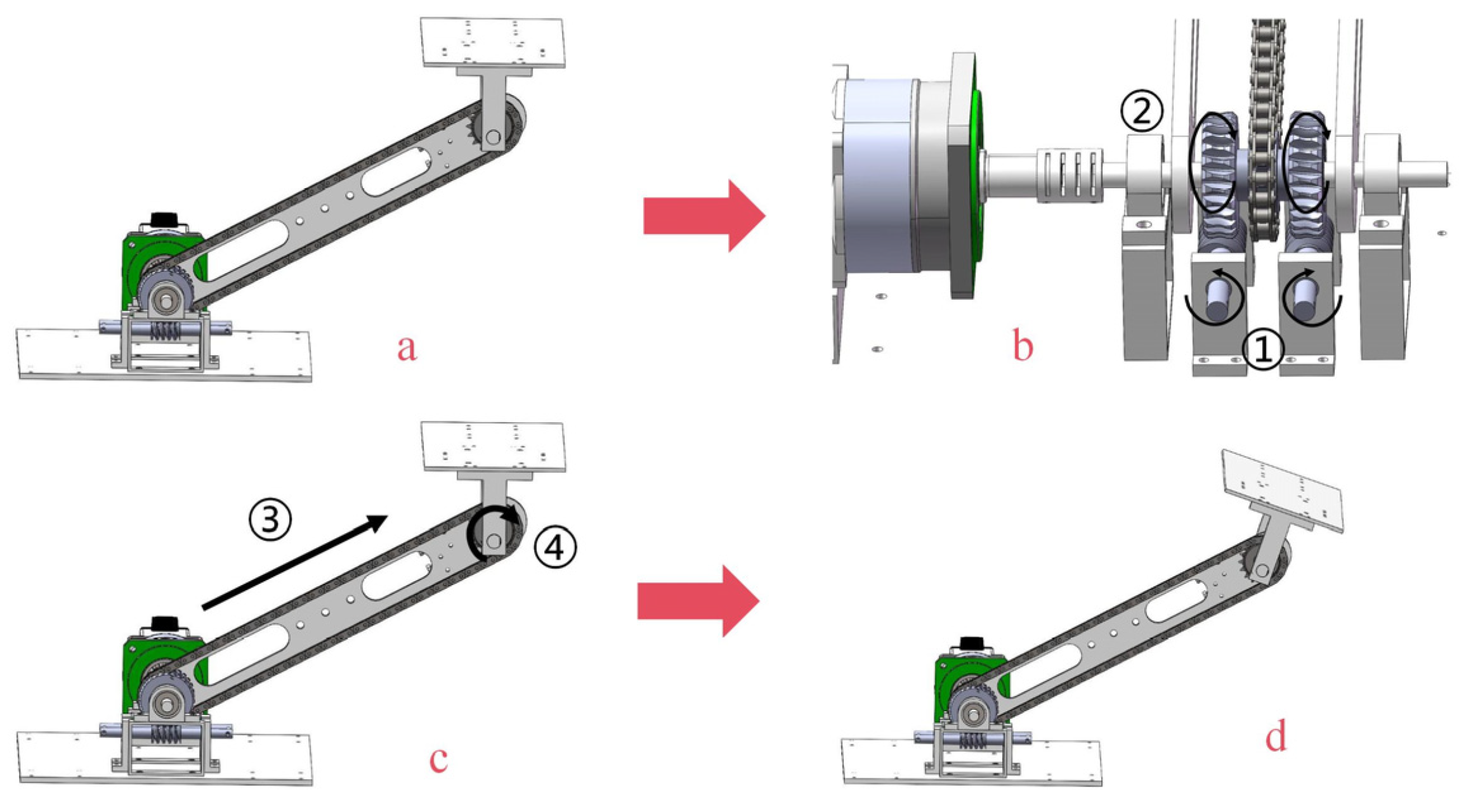
2.2. Single-Section Arm Drive Mechanism Design

The decoupling function of the chain-driven decoupled robotic arm is provided by a dual-motion transfer. Dual-motion transfer is motor-reducer-driven and sprocket-chain-driven. Therefore, the correct selection of the motor-reducer determines the successful operation of the arm, and the correct selection of the chain transmission mechanism determines the successful realization of the robot arm’s decoupling function. In the chain-driven decoupled robotic arm design, we first determined the load capacity of the robotic arm. Then, in combination with the mass and length of other components, such as the support arm plate, the selection of the sprocket chain was determined by moment analysis. Finally, the overall moment analysis of the robotic arm was utilized to determine the selection of the motor reducer. Since the chain-driven decoupled robotic arm application environment is low-speed, the torque analysis of the robotic arm was based on static analysis. However, it is too troublesome to analyze a certain part of the robotic arm alone. Therefore, we adopted the overall analysis method to integrate some parts as a whole and analyze them in an overall way.
In the design of a mini-experimental prototype, firstly, the limit load of 4 kg was proposed. Both sections of the support arm plate were 400 × 54 × 8 (mm), with a total weight of 0.8 kg. The total weight of the end platform and connection plate was 1 kg.

2.2.1. Sprocket-Chain Selection

In China, chain-driven systems enable many applications due to their superior accuracy ratio, high efficiency, high power, and low tension force [21,22,23]. In the design of the chain-driven decoupled robotic arm, the load, the end platform, and the connection plate are regarded as a whole. The sprocket chain pulls back on the chain-driven shaft during movement; therefore, the chain should withstand the maximum torque caused by this whole on the chain-driven shaft. The instantaneous process during the motion is shown in Figure 5.
In the mini-experimental prototype design, the size of G, L is known, G is 50 N, L is 200 mm, and the torque on the driven shaft is calculated as follows:
F max × R d = G × Lcos θ 1
When θ1 = 0, the chain is affected by the maximum torque at this time, and the formula is as follows:
F max × R d = G × L = 50 × 0 . 2 = 10 N M
In chain selection, the manufacturer will directly give parameters such as ultimate tensile load, radius of indexing circle, pitch, engagement clearance, etc., of the sprocket chain. Therefore, it is only necessary to multiply two parameters of the ultimate tensile load of the sprocket chain and the radius of the indexing circle directly. As long as the result is much larger than 10 N∙M, then the chain of this type can be selected. In addition, when selecting the sprocket chain, the index circle diameter had better be close to the size of the supporting arm plate. Based on the above considerations, a 06b sprocket chain was finally adopted with 99 links, 17 teeth, indexing circle radius 55 mm. The engagement clearance of the sprocket chain was 0.6 mm, the ultimate tensile load was 9.0 KN, and the total weight of the sprocket chain was 1.1 kg. In addition, according to the ultimate tensile load of the sprocket chain, the sprocket chain was much more than the actual use requirements. Therefore, the sprocket chain had a good safety performance, and then to prolong the useful life of the sprocket chain, the sprocket chain would need to be tensioned and lubricated regularly.

2.2.2. Motor-Reducer Selection

In the movement process of a chain-driven decoupled robotic arm, the motor-reducer needs to overcome the torque created by the gravity of the end platform load and the gravity of the support arm plate itself to drive the arm successfully. Since the chain-driven decoupled robotic arm application environment is low-speed, the torque analysis of the robotic arm is based on static analysis. In the analysis, the support arm plate and the sprocket chain can be approximated as a whole, and the load, the end platform, and the support plate can be approximated as a whole. Thus, the moment analysis of the decoupled robotic arm on the driving shaft is shown in Figure 6.
G is 50 N, G2 is 20 N, L1 is 400 mm, and L2 is 200 mm. Taking the center of the end face of the driving shaft as the origin, the moment Mp of the robotic arm on the driving shaft is calculated by the following equation:
M p = G 1 × L 1 cos θ 1 + G 2 × L 2 cos θ 2
When the rotation angle of the mechanical arm is 0°, the torque is maximal. Thus, the minimum torque Mp is solved for as follows:
M p = G 1 × L 1 + G 2 × L 2 = 50 × 0 . 4 + 20 × 0 . 2 = 24 N M
Currently, Mp is only an approximate range under the theory. In order to enable the motor to fully satisfy the requirements, it is necessary to formulate a suitable safety factor k. Combined with the use of requirements, the mini-experimental prototype safety factor is set to 1.5. And then the minimum withstand torque of the motor becomes 36 N·M, and finally, a 60 servo motor with 1:36 reduction ratio is used. The weight of the motor-gearbox system is 2 kg, and the total weight of a single-section robot arm is 5 kg. In addition, to ensure the safety of the robotic arm, the servo motor needs to be installed with a brake function to prevent the arm from falling due to malfunction or power failure.

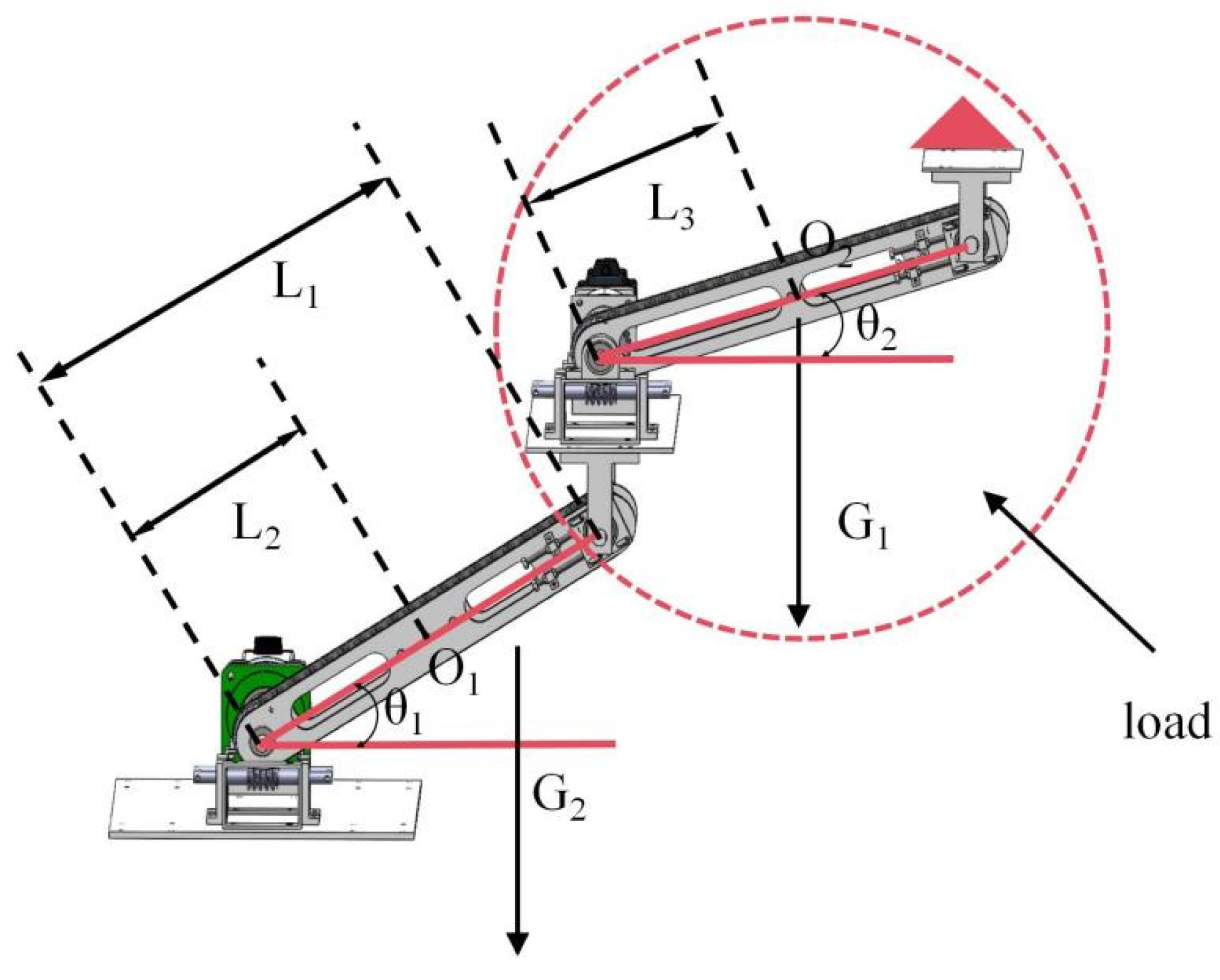
2.3. Two-Section Arm Drive Mechanism Design

In a chain-driven decoupled robotic arm system consisting of two chain-driven decoupled robotic arms, the sprocket chain and motor reducer of the first section of the arm suffer from the highest torque. Therefore, it is necessary to re-select the motor reducer and sprocket chain for the first section of the robot arm, and the motor reducer and sprocket chain for the second section of the robot arm are designed in the same way as before.

2.3.1. Sprocket-Chain Selection

In torque analysis, the end platform of the first robot arm and the second robot arm can be regarded as a whole. And then the center of the second section of the robotic arm support arm plate is approximated as the center of gravity. The torque analysis process is shown in Figure 7.
G is 110 N, L is 200 mm, then the torque on the chain is calculated as follows:
F max × R d = G × Lcos θ
When θ1 = 0, the chain is affected by the maximum torque at this time, and the formula is as follows:
F max × R d = G × L = 110 × 0.2 = 22 N M
The method of sprocket chain selection is the same as in Section 2.2.1, and the same 06b sprocket chain is finally used.

2.3.2. Motor-Reducer Selection

In two-section robotic arms, the end platform of the first section of the robotic arm and the second section of the robotic arm can be regarded as a whole at this point. Then, the motor-reducer in the first arm needs to overcome the effect of the torque on the driving shaft caused by both the gravity of the support arm plate of the first arm and the gravity of the second arm located on the end platform. The torque analysis process is shown in Figure 8.
G1 is 100 N, G2 is 20 N, L1 is 400 mm, L2 is 200 mm, and L3 is 200 mm. The moment Mp of the robotic arm on the driving shaft is calculated by the following equation:
M p = G 1 × ( L 1 cos θ 1 + L 3 cos θ 2 ) + G 2 × L 2 cos θ 1
When the rotation angle of the mechanical arm is 0°, the torque is maximal. Then, the minimum torque Mp is solved for as follows:
M p = 100 × ( 0 . 4 + 0 . 2 ) + 20 × 0 . 2 = 64 N M
Combined with a safety factor of 1.5, the minimum torque withstood by the motor becomes 96 N·M, and finally, a 90 servo motor with 1:50 reduction ratio is used. The weight of the motor-gearbox system is 6 kg.

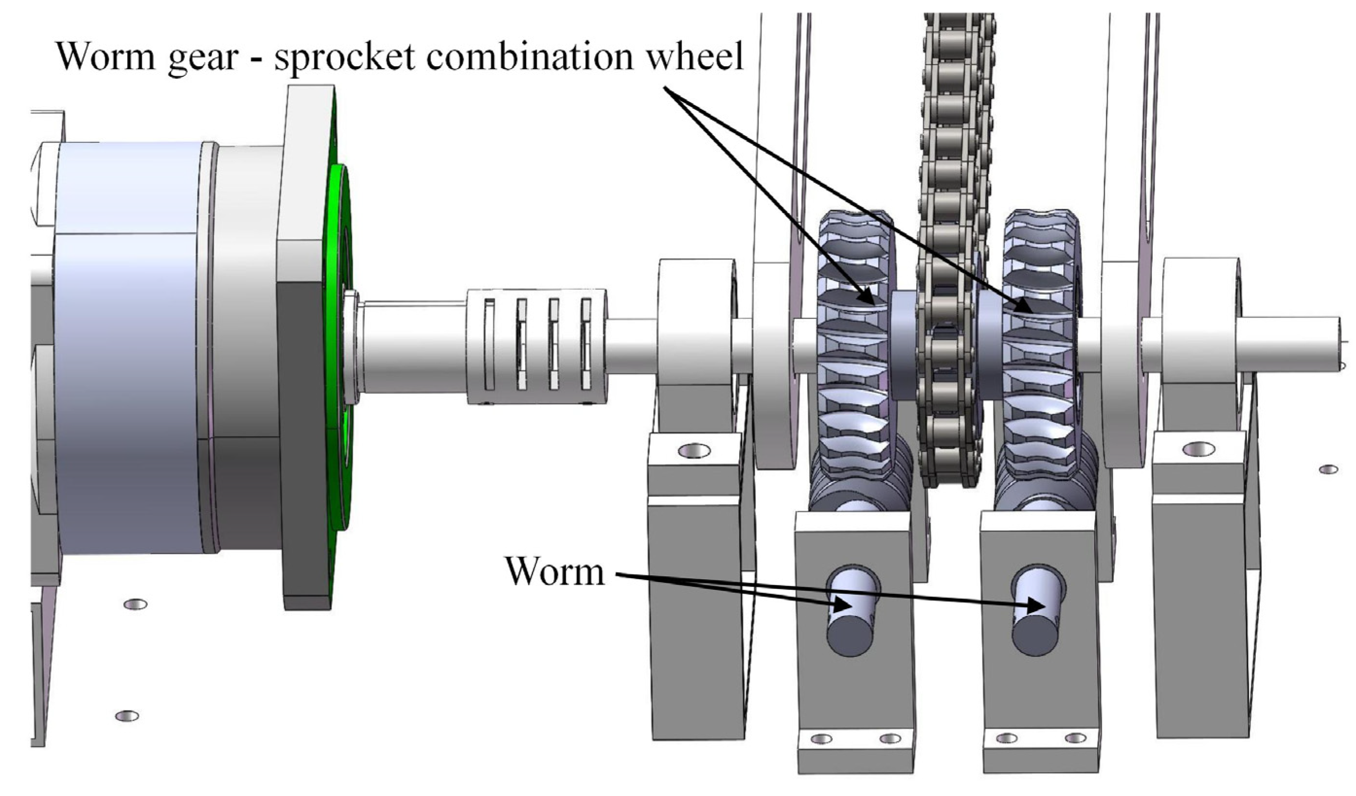
2.4. Combination Wheel Design

To ensure that the platform at the end of the arm does not move and to achieve the dual-motion transmission function, it is necessary to lock the lower sprocket concentrically installed with the driving shaft. Therefore, a special worm gear-sprocket combination is designed for the lower sprocket. A pair of worm gears are fixed in the base to complete the worm gear–worm cooperation with the combination wheel, and the upper sprocket still employs the normal sprocket. To strengthen the fastening capacity of the combined wheel, the combined wheel is composed of a worm wheel—a sprocket wheel—a worm wheel (Figure 9).
The combination wheel structure can realize two major functions in the transmission system:
First, the worm–worm gear is characterized by irreversible movement, where the worm drives the worm wheel, but the worm wheel cannot drive the worm. According to this characteristic, the design of the combination wheel can ensure that the combination wheel is fixed and locked by the worm gear under normal conditions, which can prevent the end platform from moving.
Second, the chain-driven decoupled robot arm has directional requirements for the attitude of the end platform. During initial installation and debugging, if the end platform fails to reach the goal position, then it can rotate the worm gear to drive the worm wheel movement. Subsequently, the worm wheel drives the chain movement, and finally, the chain pulls the driven shaft in reverse. As a result, the fine-tuning of the end platform attitude is completed to meet requirements (as shown in Figure 10).
Combined with the design parameters of the sprocket wheel, the worm wheel is finally determined to be 27 teeth, and the indexing circle diameter is 54 mm. Then, the corresponding worm gear indexing circle diameter is 18 mm, and the engagement clearance of the worm gear is 0.25 mm. At the same time, to improve the strength of the combination wheel, the material of the combination wheel is set as carbon steel.
In summary, the core parameters of this two-degrees-of-freedom chain-driven decoupled robotic arm mini-experimental prototype are shown in Table 1.

3. Kinematic Analysis

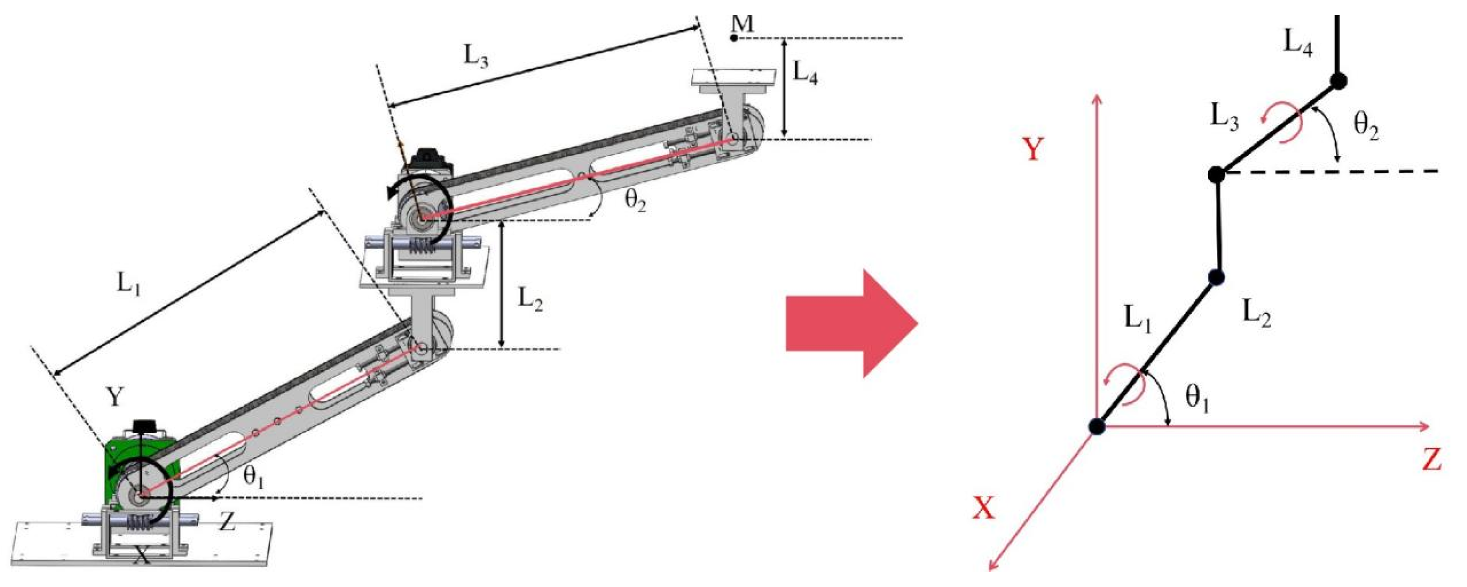
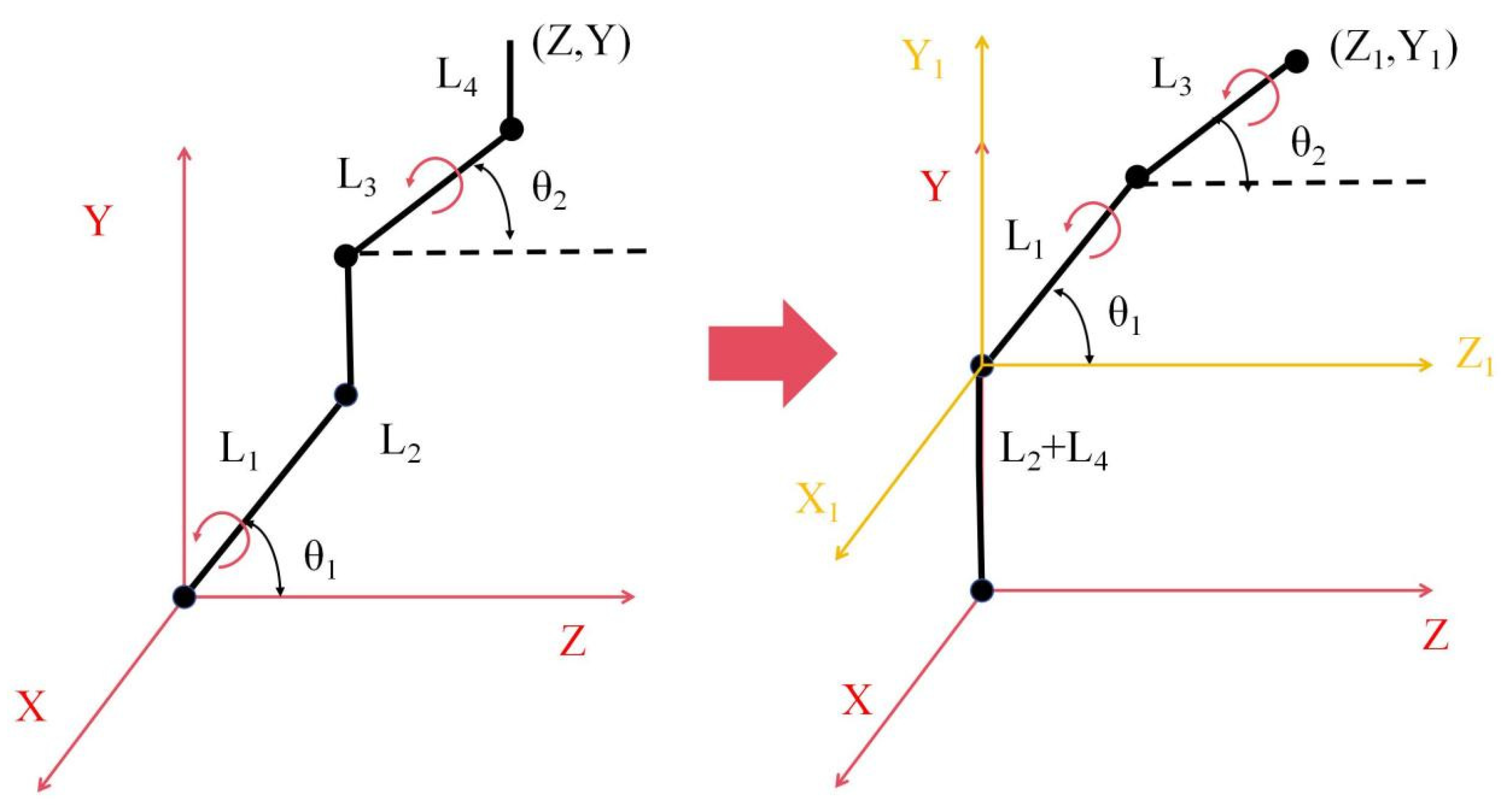
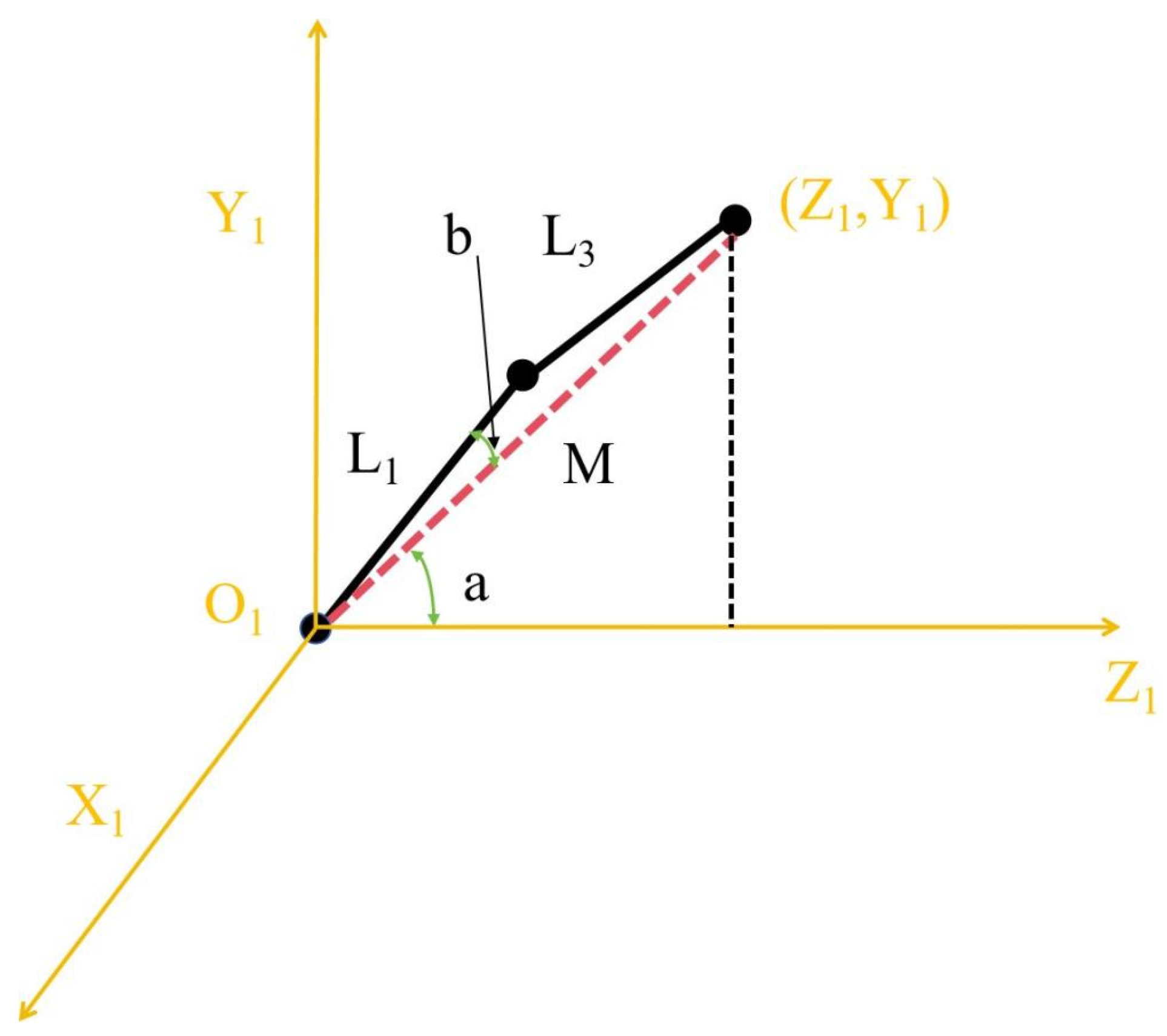
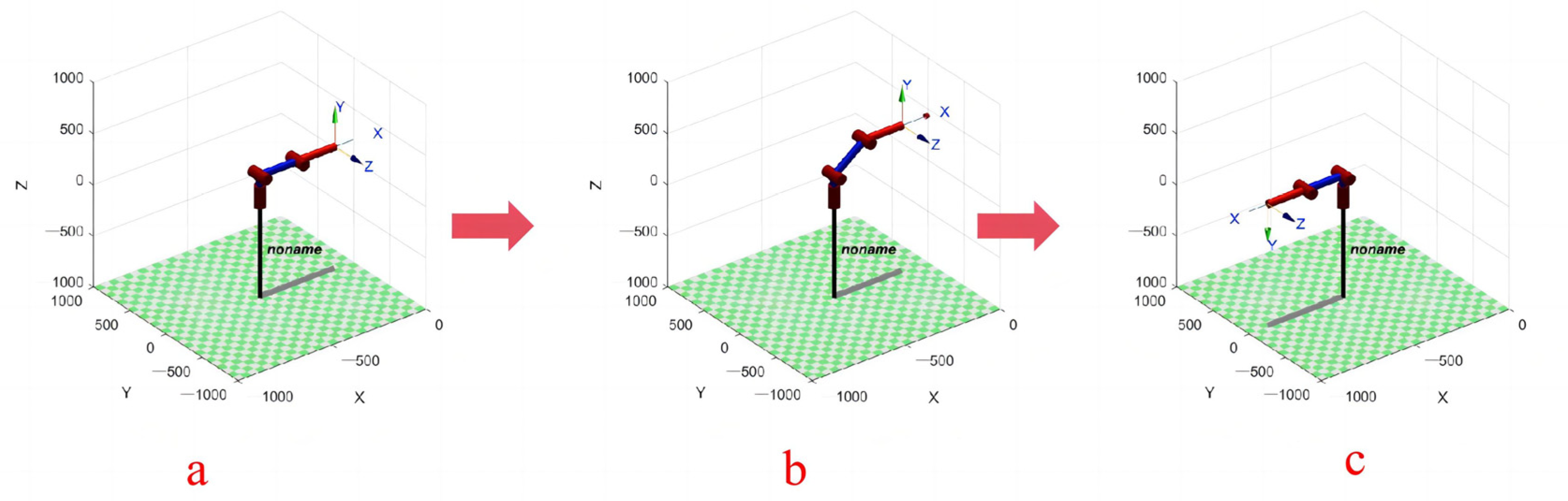
3.1. Forward and Inverse Kinematics

To accurately analyze the motion trajectory and working space of the chain-driven decoupled robotic arm system, it is necessary to perform a kinematic analysis of the chain-driven decoupled robotic arm system. Because the chain-driven decoupled robotic arm has the decoupling ability to keep the end position unchanged, it can be simplified into a linkage structure when analyzing, as shown in Figure 11.
The forward kinematics of chain-driven decoupled robotic arm systems can be transformed to obtain the end-load pose of the robotic arm with a known rotation angle of the support-arm plate. With the known rotation angle of the arm, the position of the robotic arm end can be calculated as follows:
X = 0
Y = L 1 × sin θ 1 + L 3 × sin θ 2 + L 2 + L 4
Z = L 1 × cos θ 1 + L 3 × cos θ 2
Robot inverse kinematics is the process of obtaining the angles of each joint of the robot by transforming the matrix based on the known position and posture of the robot’s end effector. The mechanical sketch shown in Figure 11 is improved, and the result is shown in Figure 12. Meanwhile, the mechanical sketch in Figure 12 is analyzed, and the results are shown in Figure 13.
The comparison of the coordinate relationships under XYZ and X1Y1Z1 shows the following:
X = X 1 = 0
Y = Y 1 + L 2 + L 4
Z = Z 1
In Figure 13, θ1 can be divided into ∠a and ∠b. First, according to the tangent theorem:
tan a = Y 1 X 1
then
a = arctan ( Y 1 X 1 )
According to the cosine theorem:
cos b = L 1 2 + M 2 L 3 2 2 × L 1 × M
where
L 1 = L 3
M = Y 1 2 + Z 1 2
then
cos b = M 2 × L 1 = Y 1 2 + Z 1 2 2 × L 1
the results are as follows:
b = arccos ( Y 1 2 + Z 1 2 2 × L 1 )
θ1 is calculated as:
θ 1 = a + b = arctan ( Y 1 X 1 ) + arccos ( Y 1 2 + Z 1 2 2 × L 1 )
According to the kinematic forward equation:
Y = L 1 × sin θ 1 + L 3 × sin θ 2 + L 2 + L 4
then
θ 2 = arcsin ( Y L 2 L 4 L 1 × sin θ 1 L 3 )
In summary, when the end load coordinates of the robotic arm are known, the angles of each joint are as follows:
θ 1 = a + b = arctan ( Y 1 X 1 ) + arccos ( Y 1 2 + Z 1 2 2 × L 1 )
θ 2 = arcsin ( Y L 2 L 4 L 1 × sin θ 1 L 3 )

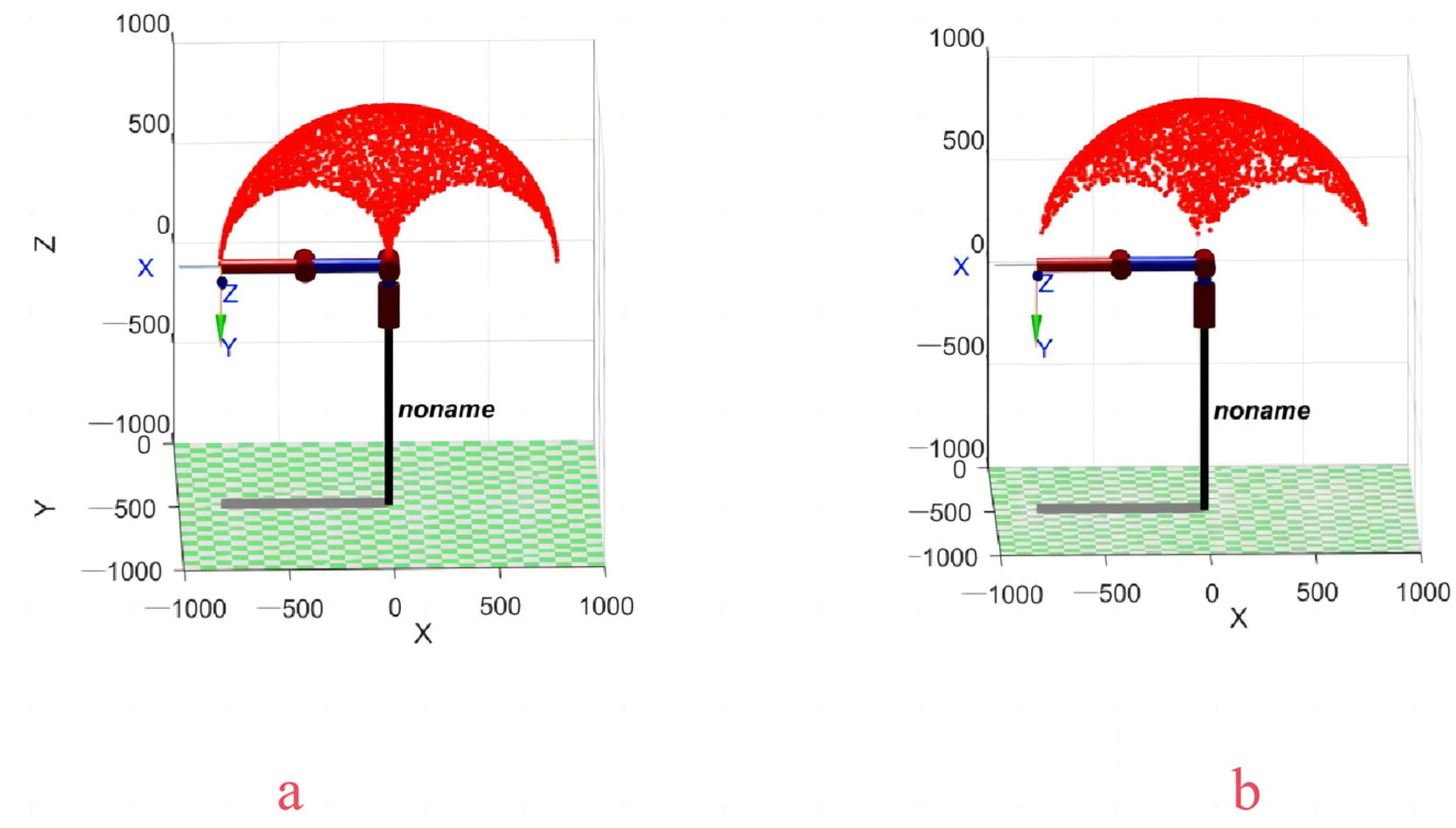
3.2. Workspace Analysis

The workspace of a chain-driven decoupled robotic arm system directly determines the application scenarios and execution capabilities of the robotic arm and is an important indicator of robot performance. In the analysis, the chain-driven decoupled robotic arm system model with the same arm length is established by MATLAB 2019. During the movement of the robot arm, the position of the end platform and the connection board are unchanged; therefore, we replace the connection board and the end platform part of the two sections of robot arm with a fixed and unchanged degree of freedom in the vertical direction below. Secondly, since the two robotic arms have no effect on each other during the movement, the compensation algorithm is added to the model. When the first robotic arm rotates θ, the second robotic arm immediately turns back an equal degree in the opposite direction to keep the position unchanged (as shown in Figure 14).
On this basis, the spatial range of motion of both robotic arms is set to 0–180°. Using the Monte Carlo method to randomly distribute the red scattering points during the movement of the robotic arm, the obtained spatial results of the robotic arm movement are shown in Figure 15.
Meanwhile, the kinematic forward solution results are plotted as images in MATLAB and compared with the kinematic spatial results of the Monte Carlo method (as shown in Figure 16). A comparison of the results shows that the two trajectories coincide, verifying the accuracy of the kinematic analysis.
In addition, the comparison of the motion space results of the parallelogram mechanism of the robotic arm suggested by Liu X.J. [15] and the chain-driven mechanism of the proposed decoupled robotic arm system are shown in Figure 17 with the same arm length. The chain-driven decoupled robotic arm has a larger workspace than the parallelogram mechanism.

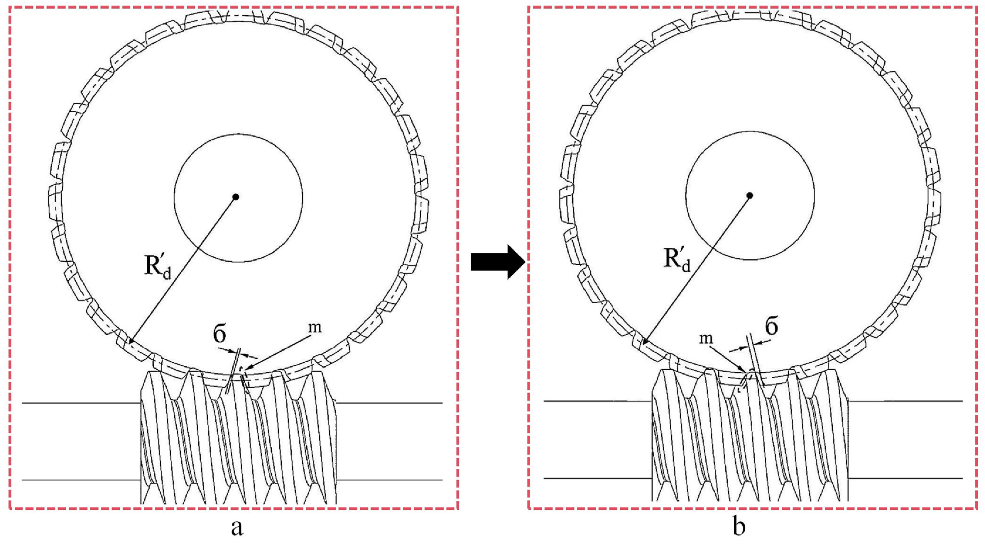
4. Engagement Clearance Error Analysis

During the motion process of the chain-driven decoupled robotic arm system, the engagement clearance of the sprocket chain and the engagement clearance of the worm gear will affect the accuracy of the dual motion transfer of the robotic arm to some extent. Therefore, the effect of the engagement clearance error caused by the transmission mechanism needs to be studied before experimentation. In this section, we will focus on exploring the degree of influence of the engagement error on the accuracy of the robotic arm and the existence conditions of the engagement clearance error, which will provide a theoretical basis for the optimization of the robotic arm in the future.

4.1. Engagement Error of Single-Section Arms

The motion trajectory process of the single-section chain-driven decoupled robotic arm is shown in Figure 18, the engagement distribution of the sprocket chain is shown in Figure 19, and the engagement distribution of the worm gear is shown in Figure 20.
First, the arm is stationary horizontally on the right (Figure 18a). At this time, the center of gravity of the arm is located on the right side relative to the driving shaft. Under the influence of the torque caused by gravity, the distribution of the engagement clearance of the sprocket chain should be as shown in Figure 19a, and the distribution of the engagement clearance of the worm gear should be as shown in Figure 20a.
In the sprocket chain engagement clearance distribution in Figure 19a, the right side of the wheel tooth maintains a close fit with the left side of the chain roller (at M in Figure 19a), and there is a clearance ϐ between the left side of the wheel tooth and the right side of the chain roller. In the engagement clearance distribution of the worm gear in Figure 20a, the left side of the worm gear teeth maintains a close fit with the right side of the worm helical teeth (at m in Figure 20a), and the right side of the worm gear teeth has an engagement clearance б with the left side of the worm helical teeth.
When the motor-reducer is activated, if the rotation angle θ is less than 90° at this point (Figure 18b), then the position of the robot arm’s center of gravity is still on the right side relative to the driving shaft. Therefore, the right side of the teeth in the sprocket chain and the left side of the chain roller can maintain a close fit during the movement (maintaining the situation at M in Figure 19a), and the left side of the teeth in the worm gear and the right side of the worm helical teeth can maintain a close fit (maintaining the situation at m in Figure 20a). Then, the chain is able to drive the sprocket steadily without any clearance obstacles. Thus, when the robot arm’s range of motion is no more than 90°, the engagement clearance of the sprocket chain and worm gear does not affect the accuracy of the decoupled robot arm’s transmission.
At the moment when the arm crosses 90° (from Figure 18c,d), the position of the center of gravity of the decoupled arm changes relative to the driving shaft; particularly, it changes from the right side to the left side due to the torque caused by gravity. At this time, the sprocket-chain engagement clearance distribution should be as shown in Figure 19b, and the worm-gear engagement clearance distribution should be as shown in Figure 20b. In the sprocket chain engagement clearance distribution in Figure 19b, the left side of the wheel tooth maintains a close fit with the right side of the chain roller (at M in Figure 19b), and there is a clearance ϐ between the right side of the wheel tooth and the left side of the chain roller. In the engagement clearance distribution of the worm gear in Figure 20b, the right side of the worm gear teeth a maintains close fit with the left side of the worm helical teeth (at m in Figure 20b), and the left side of the worm gear teeth has an engagement clearance б with the right side of the worm helical teeth. And then the position of the engagement clearance of the sprocket chain and worm gear changes at this instant, which results in transmission errors during the movement of the robotic arm and ultimately makes the end platform rotation angle missing.
Since the engagement clearance of the sprocket chain and worm gear is smaller in the transmission, the engagement clearance of the sprocket chain and worm gear can be regarded as the length of the indexing arc of the sprocket or worm gear. Φ is taken as the angular error caused by the sprocket chain, and Ψ is taken as the angular error caused by the worm gear. The equations for Φ and Ψ are as follows:
2 × π × R d × Φ 360 ° = δ
Φ = 180 ° δ π R d
2 × π × R d × Ψ 360 ° = б
Ψ = 180 ° б π R d

4.2. Engagement Error of the Two-Section Robotic Arm
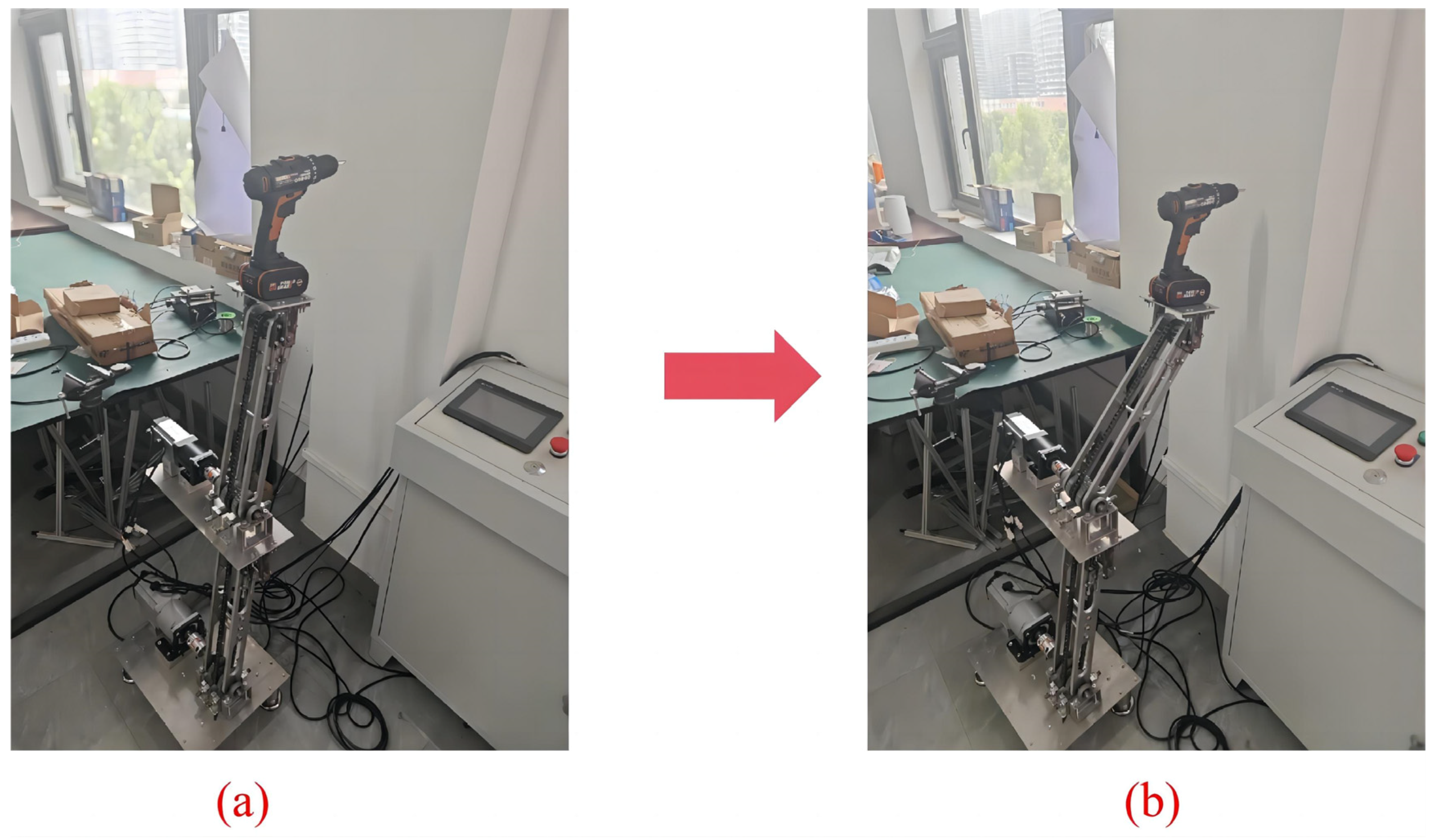
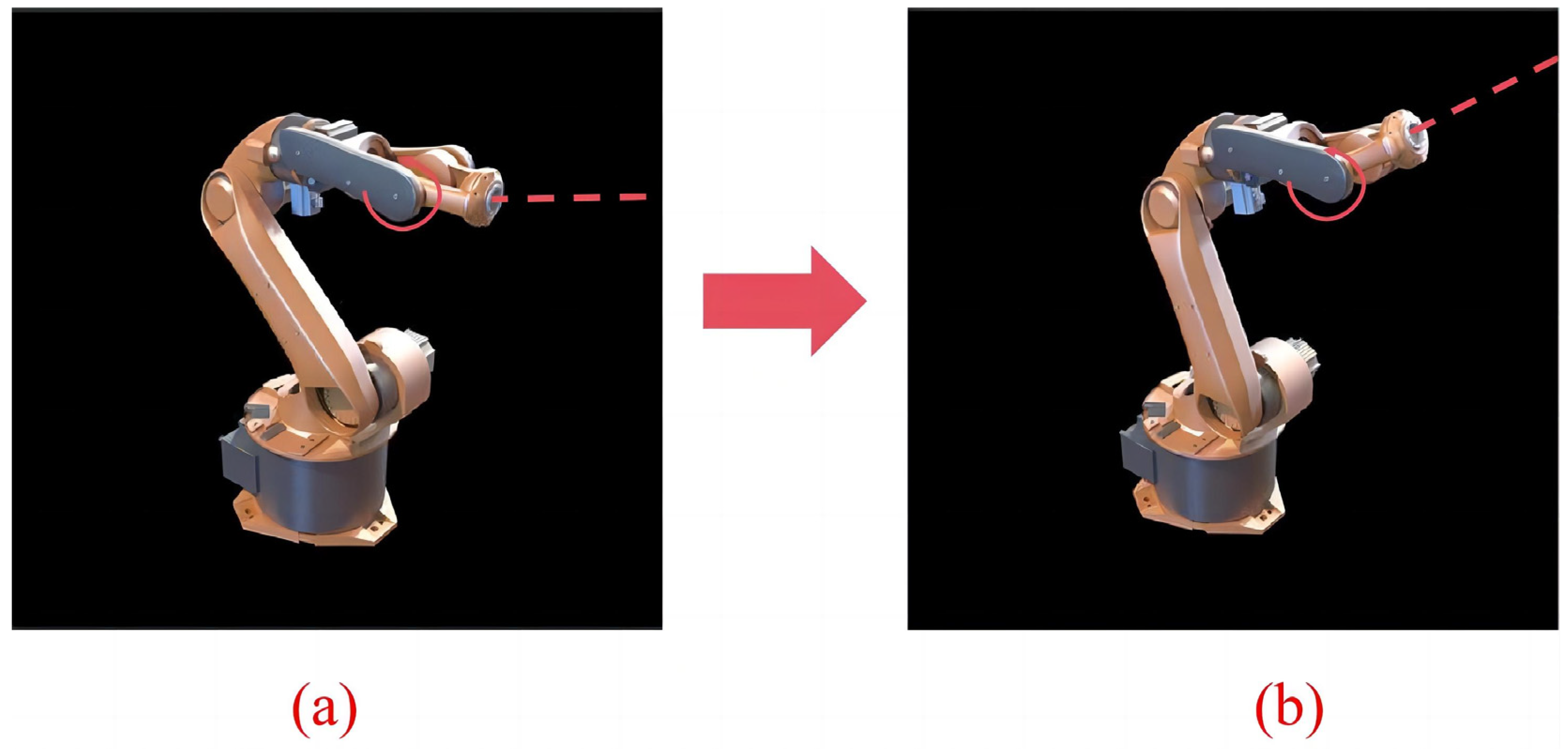
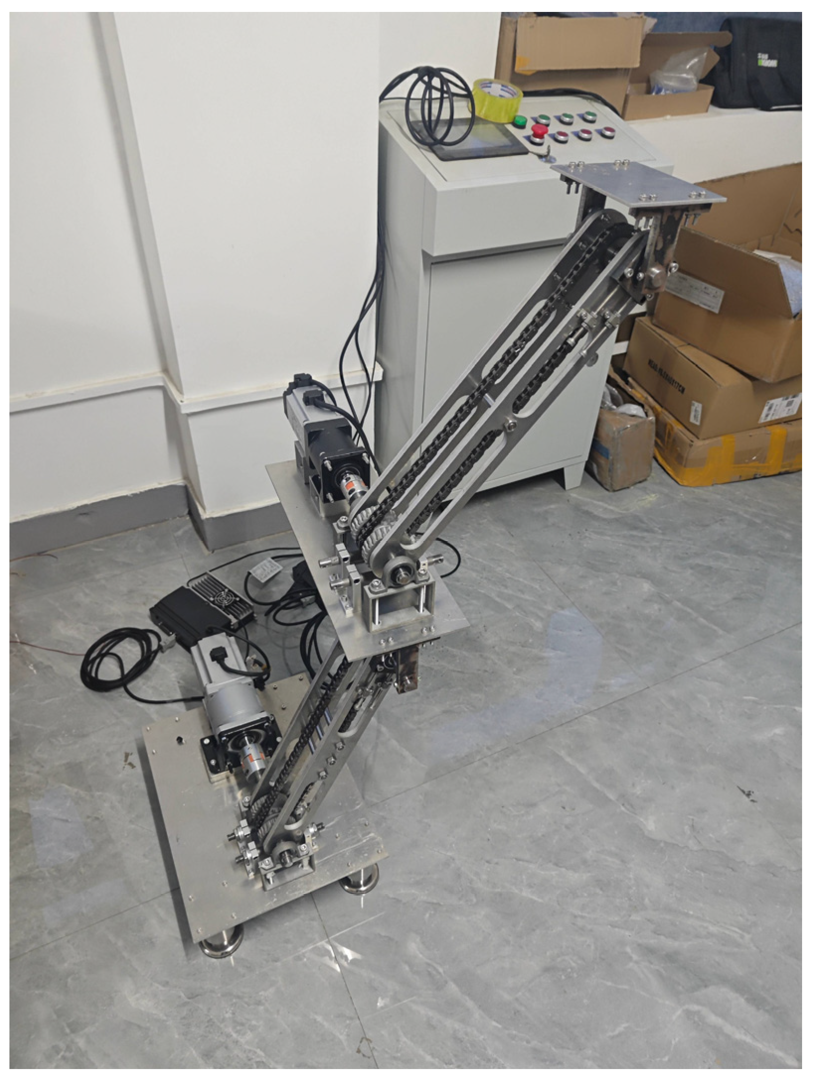
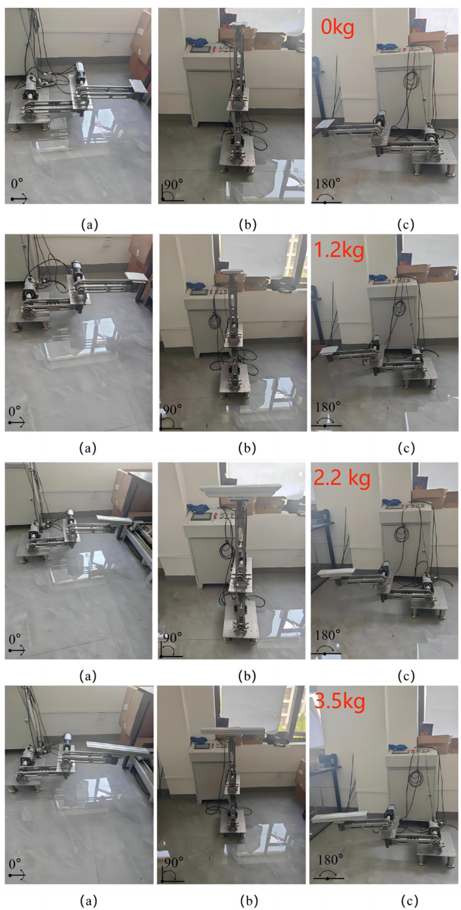
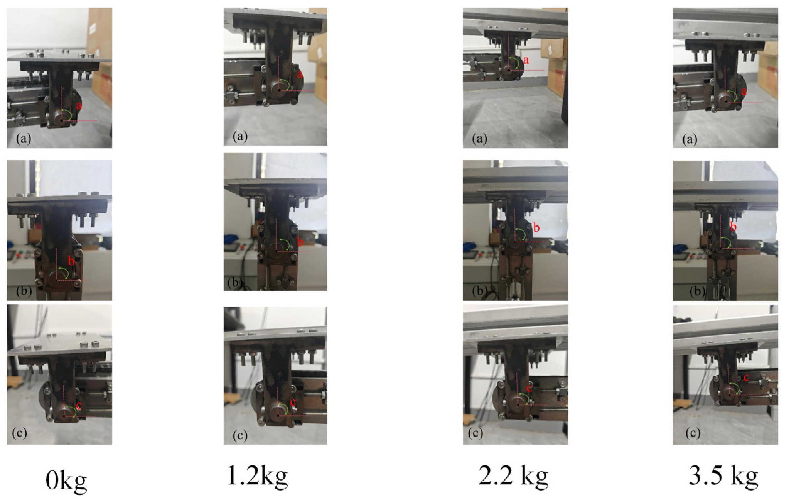
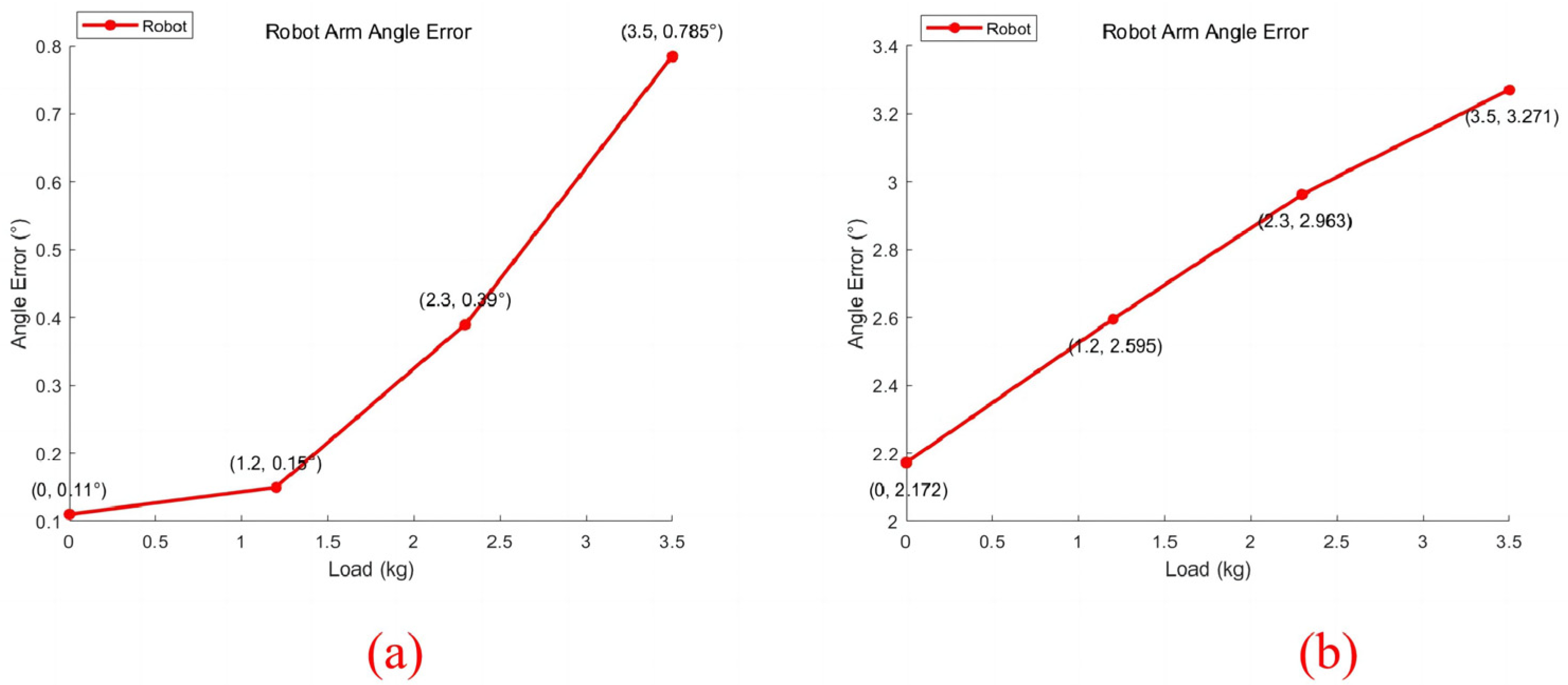
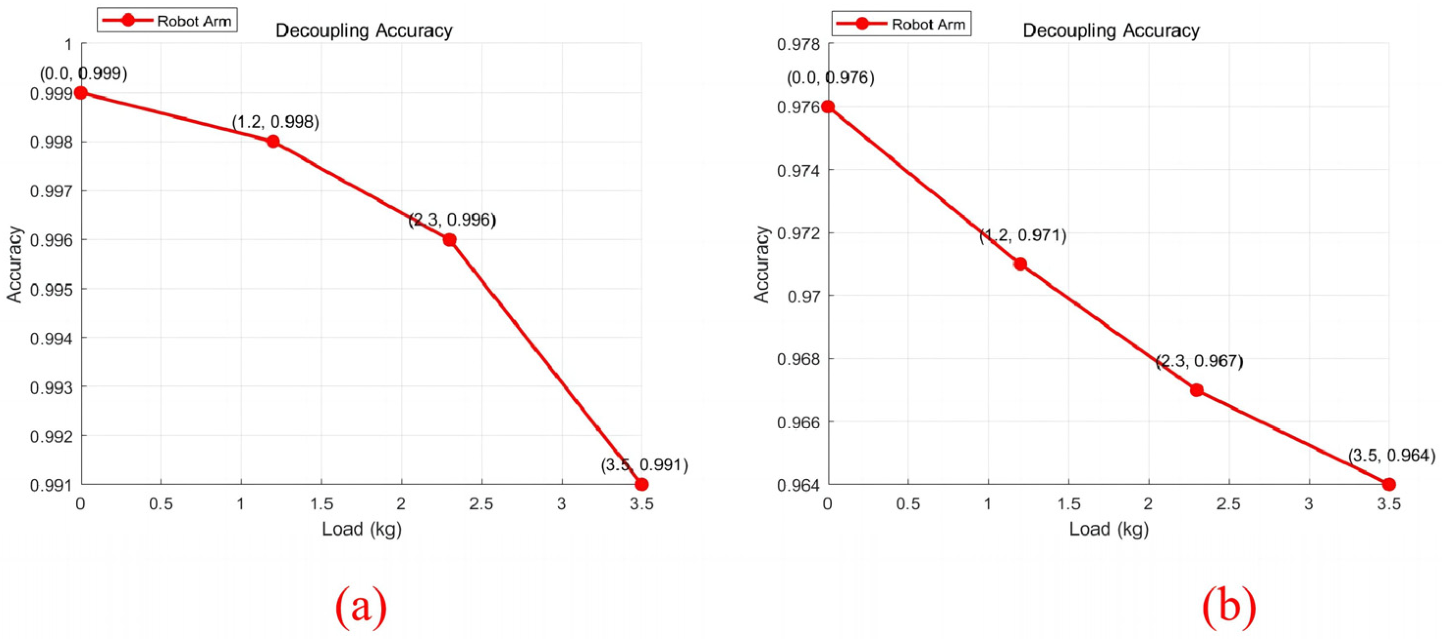
In the error analysis of the engagement clearance of the sprocket chain and worm gear of the chain-driven decoupled robotic arm system, the effect of the engagement clearance on the robotic arm is limited by the direction of rotation of the two arms’ motor-reduction gears. Figure 21 shows the motion trajectory when the two sections of the robotic arm rotate in the same direction.
When the motor-reducer is activated, if the direction of rotation of both arms is less than 90° (Figure 21b), then the positions of the two sections of the arms’ gravity centers relative to their driving shafts have not changed according to the conclusion in Section 4.1. Therefore, the position of the engagement clearance of the worm gear and sprocket chain will not change during the movement process. At that time, the engagement clearance of the transmission mechanism does not affect the transmission accuracy of the decoupled robotic arm system.
When two robotic arms are driven by a motor-reducer, one arm has a range of rotation greater than 90° and the other arm has a range of rotation less than 90° (Figure 21c). At this time, the position of the second section of the robot arm’s gravity center relative to its own driving shaft changes from the right side to the left side. The engagement clearance position of the transmission mechanism changes instantaneously, which means the rotation angle of the end-bearing platform of the robotic arm is absent. The position of the first section of the robot arm’s gravity center relative to its own driving shaft has not changed, and it remains on the right side. The position of the engagement clearance of the transmission mechanism will not change; thus, the first section of the robot arm is unaffected by the clearance during the transmission process. At this point, it is only necessary to calculate the end-load attitude error that is caused by the second section robot arm drive mechanism engagement clearance. The calculation can be carried out using Equations (25) and (26).
When both robotic arms have a rotation range of more than 90°, they are driven by the motor-reducer (Figure 21d). At this time, the position of the two sections of the decoupled arm’s gravity center relative to their own driving shafts changes from the right side to the left side. The positions of both the robot arms’ sprocket chains and worm gear engagement clearance change instantaneously, which results in a missing slewing angle of the loading platform and transmission errors. Since the direction of rotation of the two arms is the same, the engagement clearance error generated by the two arms will accumulate at this time. The inclination error due to the single-section robot arm engagement clearance is calculated using Equations (25) and (26). Then, the inclination error ε of the two sections of the robot arm’s engagement clearance is calculated as follows:
ε = 2 × Φ + 2 × Ψ
The inclination error calculation formula can provide a theoretical reference range for the robot arm’s error fluctuation caused by the engagement clearance.
In summary, if the position of the engagement clearance between the sprocket chain and the worm gear does not change during the movement process of the robotic arm, then the engagement clearance between the sprocket chain and the worm gear will not affect the transmission. If the position of the engagement clearance between the sprocket chain and worm gear changes during the movement process of the robotic arm, then the engagement clearance will cause transmission errors. Engagement clearance is an inherent feature of the transmission mechanism; therefore, the effect of errors caused by the engagement clearance is not completely eliminated. However, the generation of the engagement clearance error requires conditions. Only the torque direction of the arm’s own gravity on the driving shaft changes, which causes the position of the engagement gap error to change, resulting in a transmission error. In future robotic arm optimization, the decoupling performance of the robotic arm can be improved by avoiding the generation of engagement clearance errors.

5. Experiments

In order to verify the reliability of the chain-driven decoupled robotic arm system to ensure that it is capable of achieving the required functions, we built a mini-experimental prototype of the chain-driven decoupled robotic arm system (as shown in Figure 22). The load capacity of this prototype was about 4 kg. To reduce the overall weight of the robotic arm in the design, the sprocket chain, the driving shaft, the chain-driven shaft and the combination wheel were designed in carbon steel, and the rest of the parts were designed in aluminum.
The way to test the decoupling performance of a chain-driven decoupled robotic arm system is to study the accuracy of its real-time corrections. Therefore, the decoupling performance of the chain-driven decoupled robotic arm can be studied by researching the angle variation degree between the connection plate of the robotic arm and the horizontal end. Meanwhile, based on the engagement error analysis in Section 4, we know that when the movement range of the robotic arm is not more than 90°, there is no engagement clearance influence of the robotic arm; when the movement range of the robotic arm is more than 90°, there will be an engagement clearance error; and when both sections of the robotic arm are rotated by 90°, the robotic arm will be at the critical point of the engagement clearance error influence. Therefore, the motion space of the chain-driven decoupled robotic arm can be subdivided into the region without engagement error (0–90°) and the region with engagement error (0–180°). The experimental procedure is as follows:
First, the attitude of the end-carrying platform of the robotic arm was adjusted to be horizontal, and the initial stationary position of the robotic arm was at 0° on the right side. Then, a position picture of the robot arm’s connection board at the initial position of 0° was captured by a camera, and the angle between the robot arm’s connection board and the horizontal end at this time was calculated through image processing and recorded. In order to improve the accuracy of the calculation, 5 pictures were captured at each position, and each picture underwent image processing to calculate the angle between the connection board and the horizontal end; finally, the average value was taken.
Second, the supervisor computer sent pulses to control the servo motor, which drove the robot arm to rotate. When both arms were rotated by 90°, a camera was used to take a picture of the position of the robotic arm connection board at this moment. Image processing was used to obtain the angle between the connection board and the horizontal end at this time and recorded. And then when both arms were rotated to 180°, the same method was used to record again.
Finally, we compared the data recorded at 90° and 180° with the data recorded at the initial state of 0°. And then the angle change degree between the connection board and the horizontal end reflected the accuracy of the position decoupling of the chain-driven decoupled robotic arm.
In addition, in order to verify whether the load capacity of the robotic arm was close to the initially set 4 kg and to verify the effect on the decoupling performance of the robotic arm with different loads, we conducted the same experiment by adding, respectively, 1.2 kg, 2.2 kg, and 3.5 kg of load to the robotic arm under the maximum load allowance. The experimental procedure is shown in Figure 23 and Figure 24, and the results of the experiment are shown in Table 2, Table 3, Table 4 and Table 5.
The data above were processed to calculate the angle change between the connection board and the horizontal end of the robotic arm at different loads in the two operating conditions of no engagement error region (0–90°) and the existence of engagement error region (0–180°), the results of which are shown in Figure 25. The real-time correction accuracy of the chain-driven decoupled robotic arm was calculated based on the fluctuation of the angle change, the results of which are shown in Figure 26.
As shown in Figure 25, the load capacity of the robot arm was close to 4 kg, which is consistent with the design expectations. Within the load allowable range, the decoupling performance of the robotic arm began to decrease as the load increased. When no engagement clearance error exists during the movement of the robotic arm (shown in Figure 25a), the maximum angle change between the connection board of the robotic arm and the horizontal end is 0.785°, and the minimum accuracy of the real-time correction of the transmission mechanism is 99.1%. This is caused by a slight deformation of the arm due to the gravity of the load. The real-time correction error of the robotic arm is small in this period, and the decoupling performance is stable.
When the engagement clearance error exists during the movement of the robotic arm (shown in Figure 25b), according to the conclusion in Section 4, the robotic arm suffers twice the engagement error at this time. The decoupling performance of the robotic arm will be affected to some degree due to the influence of both the engagement clearance error and the deformation error. According to the results in Figure 25b, the maximum angular error of the robotic arm is at 3.291°, and the lowest accuracy of the real-time correction is 96.4%. Although the accuracy of real-time correction declined, it remained at a high level. Overall, the chain-driven decoupled robotic arm system can achieve the decoupling function stably.

6. Conclusions and Future Work

6.1. Conclusions

In this paper, we propose a position-decoupling method to mechanically correct the end position of a robot arm in real time through dual motion transmission, which adopts the mechanical decoupling form to enable the robot arm end position to remain unchanged, providing certain theoretical support and practical experience for the design requirements of related robotic arms. The main conclusions are as follows:
(1) A kinematic model of the chain-driven decoupled robotic arm system was established, and kinematic and workspace analyses of the robotic arm were completed. We compared the motion space of the parallelogram decoupled robot arm with the same decoupling function, and the results show that the chain-driven decoupled robot arm has a larger motion space under the same robot arm length.
(2) The effect of the transmission mechanism engagement clearance on the robotic arm was investigated, and the results showed that when the torque direction of the robotic arm gravity to the driving shaft is changed, the position of the transmission mechanism engagement clearance also changes instantaneously, which affects the decoupling performance. This theoretically gives the formula for the inclination error. In addition, the study finds that the engagement clearance is an inherent feature of the sprocket chain and cannot be completely eliminated, but the generation of the engagement clearance error requires the condition that the torque direction of the robotic arm’s own gravity on the driving shaft is changed, which provide new ideas for the optimization of the decoupled robotic arm system in the future.
(3) We built a mini-experimental prototype with a load of about 4 kg and tested the decoupling performance of the mini-experimental prototype. The experimental results show that the decoupling performance of the arm will start to decrease as the load on the arm increases during the load allowance range. However, different working areas have different degrees of reduction. Without the influence of the engagement clearance, the robotic arm has a high decoupling performance with a minimum accuracy of 99.1%; with the influence of the engagement clearance, the decoupling performance of the chain transmission robotic arm system is relatively reduced, but still has an accuracy of more than 96.4%. Overall, the chain-driven decoupled robotic arm can achieve the decoupling function stably.

6.2. Future Work

In the future, we will optimize the robotic arm based on existing findings. First, we will reduce the impact of the engagement clearance error on the robotic arm. In the currently designed robotic arm, the movement range of the robotic arm is (0–180°). Therefore, when the robot arm crosses 90°, the torque direction of the robot arm’s own gravity on the driving shaft changes, resulting in the impact of the engagement clearance error. We will put the arm on one side in the future design, and then the motion range will become (−90–90°), which makes the torque direction of the robot arm’s own gravity on the driving shaft unchanged, avoiding the influence of the engagement clearance error. Moreover, the current chain-driven decoupled robotic arm can only move in one spatial plane. And in order to enhance the movement space of the robotic arm, we will combine the robotic arm with the conveyor belt or turntable to improve the working space of the robotic arm. Finally, high-strength materials such as carbon steel will be used in the material selection of the support arm plate to reduce the deformation error of the robotic arm.
In the future, we will combine an optimized chain-driven decoupled robotic arm system with vision and control and fix a chiseling machine on the end platform for bridge chiseling application (as shown in Figure 27). The control program is as follows:
First, the vision system is used to obtain the center position coordinates of the bridge hole, and the corresponding rotation angle under this coordinate is calculated by kinematic inverse solution.
Then, the supervisor computer establishes communication with PLC and outputs the angle pulse signal to PLC. Lastly, the PLC controls the servo motor location mode to send the chiseling machine to the bridge hole to complete the chiseling operation.
In recent years, flexible robotic arms have been widely used in medical treatment, picked due to their soft texture, high adaptability, and stability [24,25], which also provides a new direction for our next research ideas. In the future, we will consider combining a robotic arm with a flexible gripper (as shown in Figure 28) to complete product grabbing with one degree of freedom. In addition, it can also realize the unchanged pose of the product during gripping.

Author Contributions

Conceptualization, Z.M. and C.D.; methodology, Z.M. and C.D.; formal analysis, Z.M., C.D., L.L. and B.T.; investigation, C.D., L.L. and B.T.; resources, Z.M.; data curation, Z.M. and L.L. and B.T.; writing—original draft preparation, C.D.; writing—review and editing, Z.M., C.D., L.L. and B.T. All authors have read and agreed to the published version of the manuscript.

Funding

This research was funded by the National Natural Science Foundation of China. Fund No. 52005181.

Data Availability Statement

The data presented in this study are available on request from the corresponding author. The data are not publicly available due to privacy restrictions.

Conflicts of Interest

The authors declare no conflicts of interest.

References

  1. Nao, E.; Avi, C.; David, Z. Modeling, simulation, and experiments of a flexible track robot over rigid horizontal and inclined surfaces. Mech. Mach. Theory 2024, 11, 105689. [Google Scholar]
  2. Taylan, A.; Evren, S. A robotic gripper for picking up two objects simultaneously. Mech. Mach. Theory 2018, 121, 583–597. [Google Scholar]
  3. Salvatore, D.; Carlo, A.; Paolo, T. ROS-Industrial based robotic cell for Industry 4.0: Eye-in-hand stereo camera and visual servoing for flexible, fast, and accurate picking and hooking in the production line. Robot. Comput.-Integr. Manuf. 2023, 80, 102453. [Google Scholar]
  4. Liu, Y.; Yi, W.; Feng, Z.; Yao, J.; Zhao, Y. Design and motion planning of a 7-DOF assembly robot with heavy load in spacecraft module. Robot. Comput.-Integr. Manuf. 2024, 86, 102645. [Google Scholar] [CrossRef]
  5. Manoonpong, P.; Rajabi, H.; Larsen, J.C.; Raoufi, S.S.; Asawalertsak, N.; Homchanthanakul, J.; Tramsen, H.T.; Darvizeh, A.; Gorb, S.N. Fin Ray Crossbeam Angles for Efficient Foot Design for Energy-Efficient Robot Locomotion. Systems. Adv. Intell. Syst. 2022, 4, 102645. [Google Scholar]
  6. Zhou, X.; Wang, X.; Xie, Z.; Li, F.; Gu, X. Online obstacle avoidance path planning and application for arc welding robot. Robot. Comput. Manuf. 2022, 78, 102413. [Google Scholar] [CrossRef]
  7. Cai, Z.; Deng, S.; Liao, H.; Zeng, C.; Montavon, G. The Effect of Spray Distance and Scanning Step on the Coating Thickness Uniformity in Cold Spray Process. J. Therm. Spray Technol. 2014, 23, 354–362. [Google Scholar] [CrossRef]
  8. Zhang, R.; Wu, J.; Wang, Y. Stability analysis of a novel mobile spray-painting robot for touch-up painting in vehicle repair plant. J. Mech. Sci. Technol. 2022, 36, 2571–2584. [Google Scholar] [CrossRef]
  9. Wang, X.; Zhang, D.; Zhao, C.; Zhang, H.; Yan, H. Singularity analysis and treatment for a 7R 6-DOF painting robot with non-spherical wrist. Mech. Mach. Theory 2018, 126, 92–107. [Google Scholar] [CrossRef]
  10. Qi, Y.Q.; Li, Y.W.; Chen, Z.M.; Kong, F.D.; Yang, X.K.; Zhu, W.G. Dseign and kinematics’analying of a serial nine-degree-of-freedom spraying robot. J. Mech. Eng. 2021, 56, 165–171. (In Chinese) [Google Scholar]
  11. Xu, F.; Zi, B.; Yu, Z.; Zhao, J.; Ding, H. Design and implementation of a 7-DOF cable-driven serial spray-painting robot with motion-decoupling mechanisms. Mech. Mach. Theory 2024, 192, 105549. [Google Scholar] [CrossRef]
  12. Wang, L.; Fang, Y.F.; Zhang, D. Design of 4-DOF hybrid parallel robots with an integrated three-fingered robot end effector. Mech. Mach. Theory 2023, 189, 105443. [Google Scholar] [CrossRef]
  13. Qian, L.; Liu, P.; Lu, H.; Shi, J.; Zhao, X. An End-to-End Inclination State Monitoring Method for Collaborative Robotic Drilling Based on Resnet Neural Network. Sensors 2024, 24, 1095. [Google Scholar] [CrossRef] [PubMed]
  14. Qian, J.; Su, Q.; Zhang, F.; Ma, Y.; Fang, Z.; Xu, B. Static Deformation-Compensation Method Based on Inclination-Sensor Feedback for Large-Scale Manipulators with Hydraulic Actuation. Processes 2020, 8, 81. [Google Scholar] [CrossRef]
  15. Liu, X.J.; Li, J.; Zhou, Y.H. Kinematic optimal design of a 2-degree-of-freedom 3-parallelogram planar parallel manipulator. Mech. Mach. Theory 2015, 8, 1–17. [Google Scholar] [CrossRef]
  16. Chai, M.; Yuan, Y.; Zhao, W. An improved particle swarm optimization algorithm for dynamic analysis of chain drive based on multidisciplinary design optimization. Adv. Mech. Eng. 2019, 11, 1687814019829611. [Google Scholar] [CrossRef]
  17. Fuglede, N.; Thomsen, J.J. Kinematics of roller chain drives—Exact and approximate analysis. Mech. Mach. Theory 2016, 100, 17–32. [Google Scholar] [CrossRef]
  18. Grinschgl, M.; Reich, F.; Abeltshauser, R.; Eder, M.; Antretter, T. New approach for the simulation of chain drive dynamics with consideration of the elastic environment. Proc. Inst. Mech. Eng. Part K J. Multi-Body Dyn. 2017, 231, 103–120. [Google Scholar] [CrossRef]
  19. Fuglede, N.; Thomsen, J.J. Kinematic and dynamic modeling and approximate analysis of a roller chain drive. J. Sound Vib. 2016, 366, 447–470. [Google Scholar] [CrossRef]
  20. Wang, W.; Liu, H.; Cai, G.; Zhang, P. Design and simulation analysis of inner-outer compound meshing silent-chain plate. J. Mech. Sci. Technol. 2023, 37, 4757–4766. [Google Scholar] [CrossRef]
  21. Yang, J.; Feng, Z.; Gao, H.; Wang, T.; Xu, K. Multibody dynamics analysis of a silent chain drive timing system. J. Mech. Sci. Technol. 2023, 37, 1653–1664. [Google Scholar] [CrossRef]
  22. Cheng, Y.; An, L.; Yin, S.; Wang, X. Multi-variation characteristic of dual phase Hy-Vo silent chain transmission system. Mech. Mach. Theory 2016, 103, 40–50. [Google Scholar] [CrossRef]
  23. Cheng, Y.; Wang, X.; Liu, H.; Gao, W.; Zhang, J. Research on multi-variation coupling effect of heart-shaped dual phase Hy-Vo silent chain system. Adv. Eng. Softw. 2017, 107, 1–6. [Google Scholar] [CrossRef]
  24. Ridremont, T.; Singh, I.; Bruzek, B.; Erel, V.; Jamieson, A.; Gu, Y.; Merzouki, R.; Wijesundara, M.B.J. Soft Robotic Bilateral Rehabilitation System for Hand and Wrist Joints. Machines 2024, 12, 288. [Google Scholar] [CrossRef]
  25. Zhang, G.; Li, S.; Wu, Y.; Zhu, M. An Investigation on the Grasping Position Optimization-Based Control for Industrial Soft Robot Manipulator. Machines 2021, 9, 363. [Google Scholar] [CrossRef]
Figure 1. Chain-driven decoupled robotic arm.
Machines 12 00410 g001
Figure 2. Principle of dual motion transmission system: ① Driving shaft rotation. ② Chain-driven shaft. ③ Sprocket-driven rotation. R1 is the radius of the driving sprocket, R2 is the radius of the driven sprocket, θ1 is the rotation angle of the driving shaft, and θ2 is the reversal angle of the driven shaft.
Machines 12 00410 g002
Figure 3. Chain-driven decoupled robotic arm usage. (a) Initial position (b) Working position.
Machines 12 00410 g003
Figure 4. Conventional multi-jointed robotic arm working trajectory. (a) Initial position (b) Working position.
Machines 12 00410 g004
Figure 5. Chain-drive force analysis. The red part is the load, G is the total gravity of the load and the end platform and connection board, L is the distance from the center of gravity of this system to the center of the sprocket, Rd is the radius of the sprocket indexing circle, and θ1 is the angle between the connection plate and the horizontal end.
Machines 12 00410 g005
Figure 6. Torque analysis of a single-section chain-driven decoupled robotic arm. G1 is the total gravity of the load, the end platform, and connection board, G2 is the support arm plate and the sprocket chain gravity, L1 is the distance between the driving and driven shaft, and L2 is the distance from the center of gravity O1 of the support arm plate of the first section of the robot arm to the driving shaft. θ1 is the angle of rotation of the first section of the robot arm.
Machines 12 00410 g006
Figure 7. Chain drive force analysis of two-section decoupled robot arm. G is the total gravity of the load, the end platform, and the connection board, L is the distance from the center of the support arm plate to the driving shaft, and Rd is the indexing circle radius of the sprocket. θ is the angle between the support plate and the horizontal end.
Machines 12 00410 g007
Figure 8. Torque analysis of a two-section decoupled robot arm. G1 is the total gravity of the load, the end platform, and the connection board, G2 is the support arm plate and the sprocket chain gravity, L1 is the distance between the driving and driven shaft, L2 is the distance from the center of the support arm plate of the first section robot arm to the driving shaft, L3 is the distance from the center of gravity of the second section robot arm to the driving shaft, θ1 is the angle of rotation of the first section of the robot arm, and θ2 is the angle of rotation of the second section of the robotic arm.
Machines 12 00410 g008
Figure 9. Combination wheel.
Machines 12 00410 g009
Figure 10. Combination-wheel system adjustment function (①-②-③-④). (a) initial position (b) worm gear transmission (c) chain transmission (d) platform position adjustment.
Machines 12 00410 g010
Figure 11. Kinematic spatial coordinate system. L1 is the distance between the driving shaft and the driven shaft of the first section of the robotic arm, L2 is the distance between the driven shaft of the first arm and the driving shaft of the second arm, L3 is the distance between the driving shaft of the second robotic arm and the driven shaft, L4 is the distance between the driven shaft of the second robotic arm and the end platform load, θ1 is the angle of rotation of the support arm plate driven by the motor reducer of the first section of the robotic arm, and θ2 is the angle of rotation of the support arm plate driven by the motor reducer of the second section of the robotic arm.
Machines 12 00410 g011
Figure 12. Improvement in spatial coordinate system. Initial coordinate system (red), improvement coordinate system (yellow).
Machines 12 00410 g012
Figure 13. Kinematic inverse analysis. Improvement coordinate system (yellow).
Machines 12 00410 g013
Figure 14. Robotic arm MATLAB model. (a) Initial 0° position (b) Motion position (c) 180° position.
Machines 12 00410 g014
Figure 15. Motion space analysis. (a) Initial 0° position (b) 180° position.
Machines 12 00410 g015
Figure 16. Results Comparison. (a) Monte Carlo movement space and (b) forward kinematics.
Machines 12 00410 g016
Figure 17. Motion space comparison of the (a) chain transmission mechanism and (b) parallelogram mechanism.
Machines 12 00410 g017
Figure 18. Motion trajectory of a single-section decoupled robotic arm. (a) 0° (b) 0–90° (c) 90° (d) 90–180°, G is the gravity of the arm.
Machines 12 00410 g018
Figure 19. Distribution of the engagement clearance of the sprocket chain. ϐ is the sprocket-chain engagement clearance, Rd is the sprocket indexing circle radius, and M is the close-fit posture of the teeth and chain. (a) Engagement clearance position (0–90°) (b) Engagement clearance position (90–180°).
Machines 12 00410 g019
Figure 20. Distribution of the engagement clearance of the worm gear. б is the engagement clearance of the worm gear, Rd’ is the radius of the worm wheel indexing circle, and m is the close-fit posture of the worm and worm wheel. (a) Engagement clearance position (0–90°) (b) Engagement clearance position (90–180°).
Machines 12 00410 g020
Figure 21. Motion process of the chain-driven decoupled robot arm system for the same direction rotation. (a) both 0° (b) both 0–90° (c) 0–90 and 90–180° (d) both 90–180°.
Machines 12 00410 g021
Figure 22. Chain driven decoupled robotic arm system.
Machines 12 00410 g022
Figure 23. Experimental procedure. (a) Initial 0° position, (b) 90° position and (c) 180° position of 0 kg, 1.2 kg, 2.2 kg and 3.5 kg.
Machines 12 00410 g023
Figure 24. Connection board position. (a) is the angle between the connection board and the horizontal direction at 0°, (b) is the angle between the connection board and the horizontal direction at 90°, (c) is the angle between the connection board and the horizontal direction at 180°.
Machines 12 00410 g024
Figure 25. Angle change between connection board and horizontal end. (a) Without engagement error region; (b) with engagement error region.
Machines 12 00410 g025
Figure 26. Real-time correction accuracy of the robotic arm. (a) Without engagement error region; (b) with engagement error region.
Machines 12 00410 g026
Figure 27. Chain-driven decoupled chiseling robot arm system.
Machines 12 00410 g027
Figure 28. Flexible gripper combination.
Machines 12 00410 g028
Table 1. Core parameters of chain-driven decoupled robotic arm system.
Name of Core ParameterDesign Result
Support arm plate454 × 54 × 8 mm
The first section of the robotic arm end load platform405 × 150 × 5 mm
The second section of the robotic arm end load platform145 × 150 × 5 mm
The first section of the robotic arm motor-reducer90 servo motor with 1:50 reduction ratio
The second section of the robot arm motor-reducer
Sprocket
Chain
Center distance of the first section of the robot arm
Length of the first section arm driven shaft to the second section arm driven shaft
Center distance of the second section of the robot arm
Total weight
Rated load
Engagement clearance of sprocket chain
Engagement clearance of the worm gear
60 servo motor with 1:36 reduction ratio
06B-17 teeth
06B-99 sections
400 mm
200 mm
400 mm
13.8 kg
4 kg
0.6 mm
0.25 mm
Table 2. The angle between the connection board and the horizontal end of the arm at 0°, 90° and 180° under 0 kg load.
Angle12345Mean
a 89.851°89.982°89.775°89.711°89.661°89.796°
b89.605°89.894°89.951°89.862°90.119°89.906°
c91.942°92.156°91.821°91.759°92.161°91.968°
Table 3. The angle between the connection board and the horizontal end of the arm at 0°, 90° and 180° under 1.2 kg load.
Angle12345Mean
a 89.862°89.541°89.618°89.636°89.728°89.629°
b89.787°89.695°89.841°89.765°89.681°89.747°
c92.167°92.233°92.091°91.350°92.281°92.224°
Table 4. The angle between the connection board and the horizontal end of the arm at 0°, 90° and 180° under 2.2 kg load.
Angle12345Mean
a 89.610°89.436°89.497°89.557°89.514°89.522°
b90.051°89.818°89.957°89.864°89.770°89.892°
c92.359°92.495°92.512°92.557°92.502°92.485°
Table 5. The angle between the connection board and the horizontal end of the arm at 0°, 90° and 180° under 3.5 kg load.
Angle12345Mean
a 89.544°89.498°89.356°89.481°89.397°89.449°
b90.012°90.189°90.204°90.170°90.193°90.154°
c92.605°92.740°92.697°92.784°92.773°92.720°
Disclaimer/Publisher’s Note: The statements, opinions and data contained in all publications are solely those of the individual author(s) and contributor(s) and not of MDPI and/or the editor(s). MDPI and/or the editor(s) disclaim responsibility for any injury to people or property resulting from any ideas, methods, instructions or products referred to in the content.

