


Enhancing Photovoltaic-Powered DC Shunt Motor Performance for Water Pumping through Fuzzy Logic Optimization
 , , , , ,
  and
and
Abstract
1. Introduction
- Introducing a novel intelligent fuzzy logic controller-based MPPT algorithm aimed at enhancing the efficiency of PV systems.
- Designing the proposed FLC-MPPT system to accommodate load variations, ranging from constant resistive loads to dynamic loads.
- Utilizing input parameters such as changes in PV voltage and power, requiring only a single current sensor and voltage divider, thus ensuring a cost-effective solution.
- Implementing an accumulation technique at a specific interval (100 µs) to derive the necessary duty cycle from the change in reference voltage, eliminating the need for a proportional–integral–derivative (PID) controller to regulate PV voltage.
- Addressing oscillation issues around the maximum power point (MPP) and enhancing response speed through temporal adjustments, particularly in comparison to the widely used perturb and observe (P&O) method.
- Conducting rigorous simulation assessments using MATLAB/Simulink, benchmarking against the conventional P&O method, showcasing reduced oscillations and improved response rates with the FLC-based MPPT algorithm.
- Validating the algorithm’s real-world effectiveness through experimental verification, employing a 120 W laboratory hardware prototype and assessing performance under resistive and water pump loads. Results obtained using a DS1104 embedded solution confirm the efficacy of the proposed FLC-based MPPT algorithm in optimizing PV module operation across diverse load conditions.
2. Simulation Setup
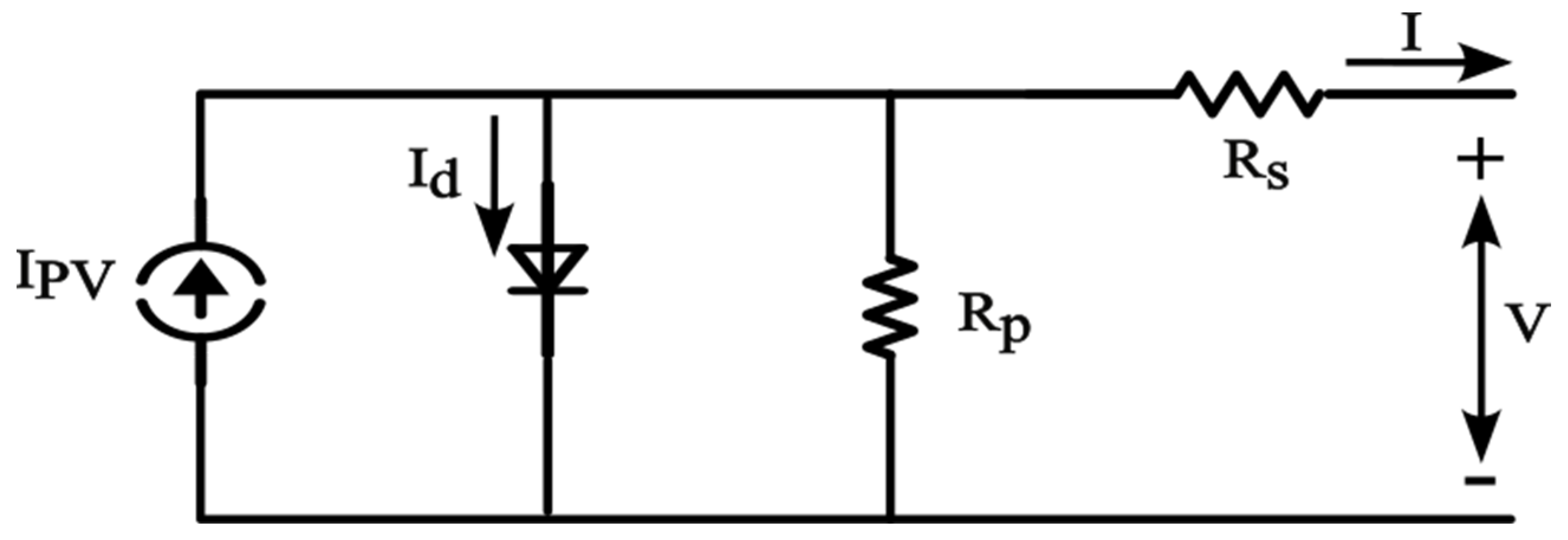
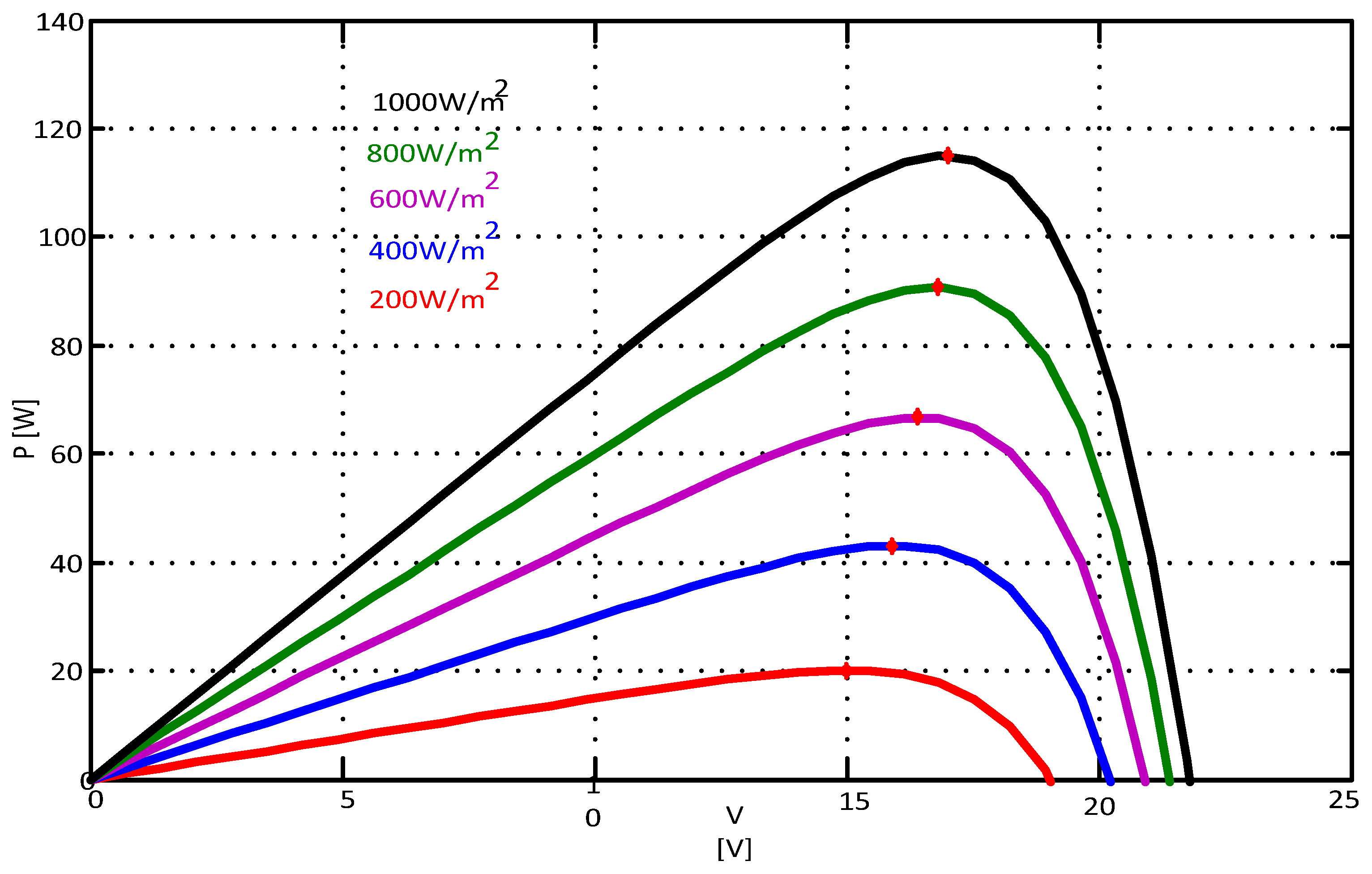
2.1. PV Module
- : Short circuit current at normal conditions (25 °C, 1000 W/m2).
- : Given cell temperature (°C).
- a: Temperature coefficient of Isc in percent change per degree temperature.
- : Nominal value of irradiance, which is normally 1000 W/m2.
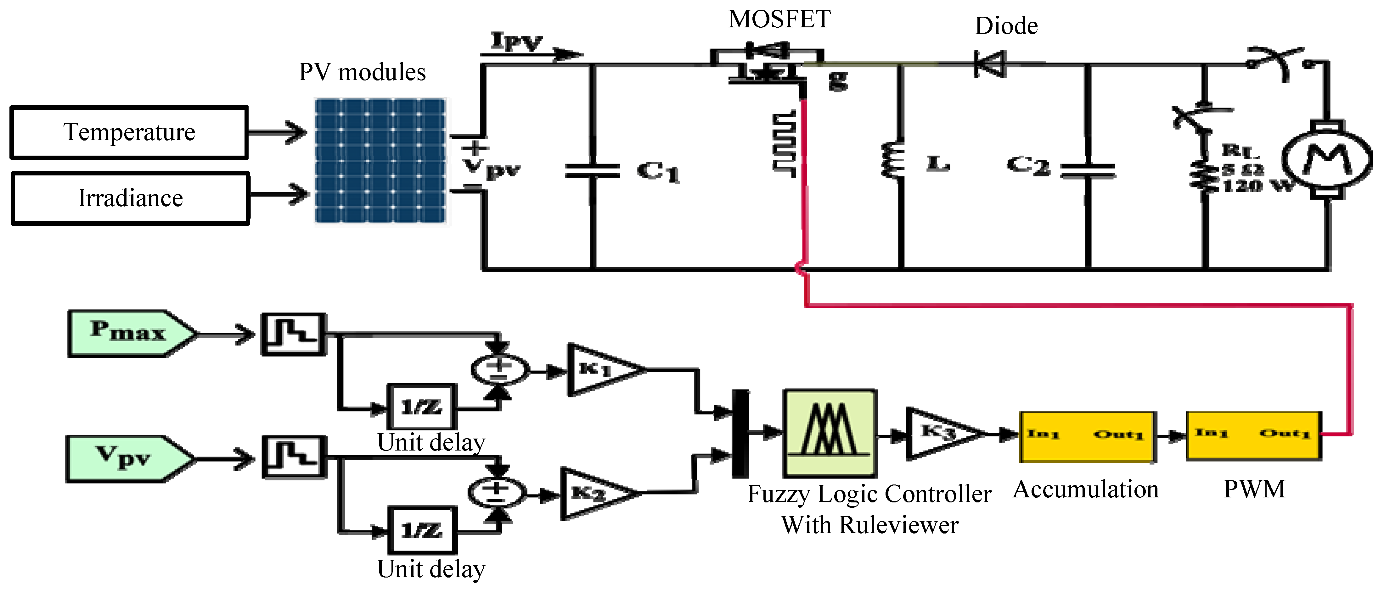
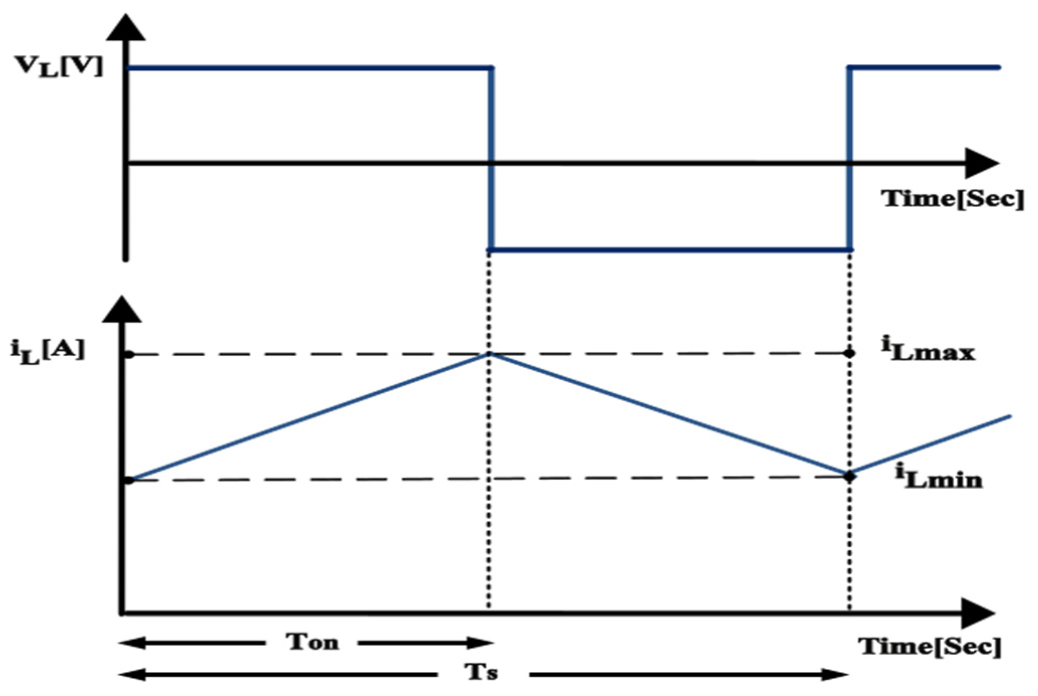
2.2. DC-DC Buck-Boost Converter
2.3. The Proposed Fuzzy Logic-Based MPPT Method
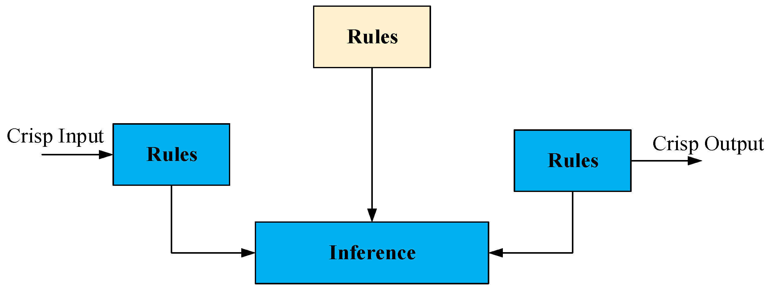
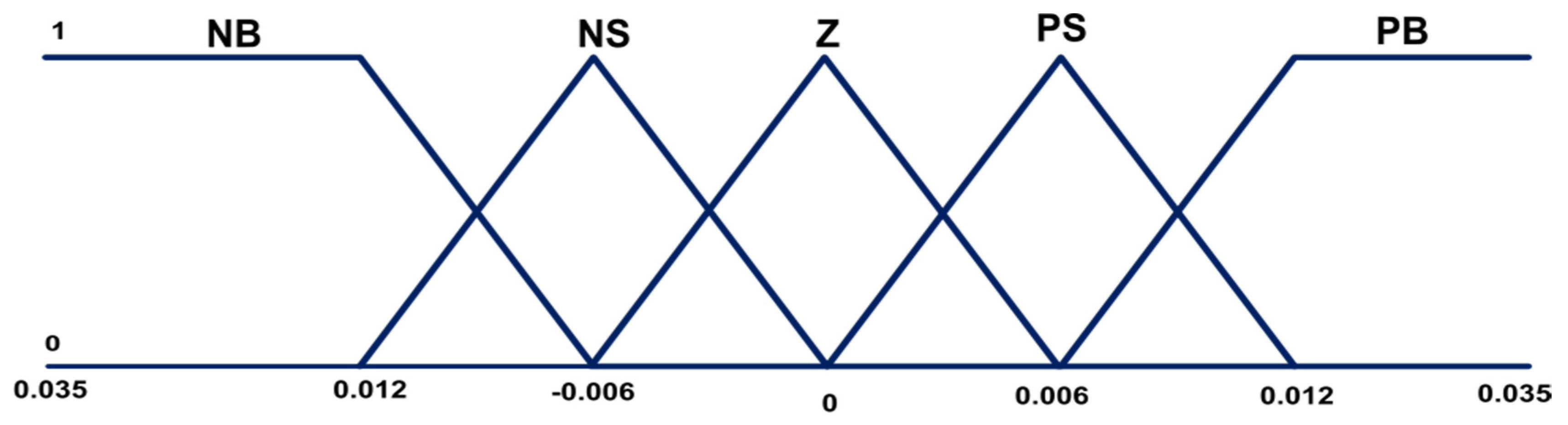
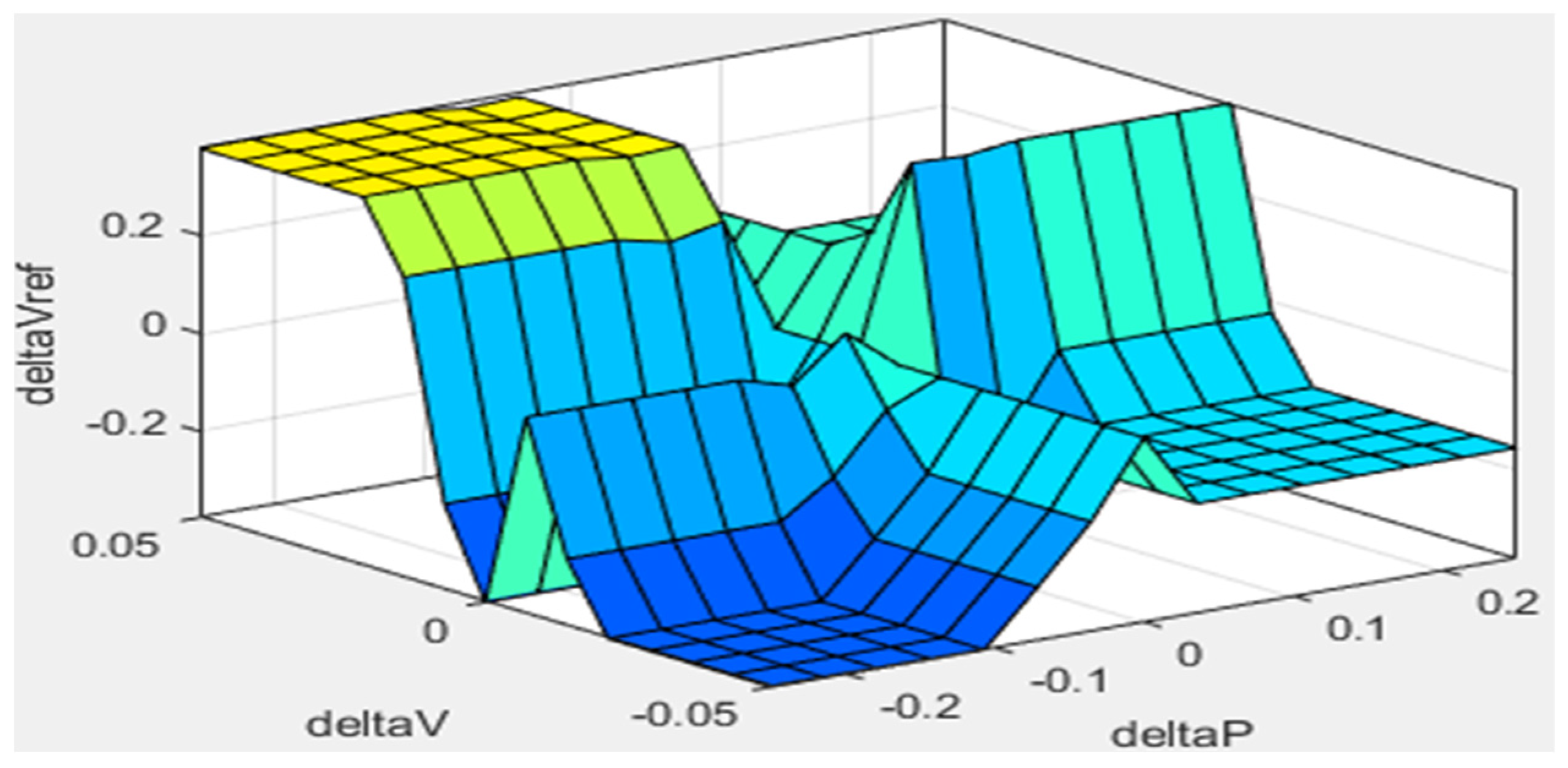
2.3.1. The Fuzzy Logic Controller
2.3.2. The Proposed FLC-MPPT Algorithm
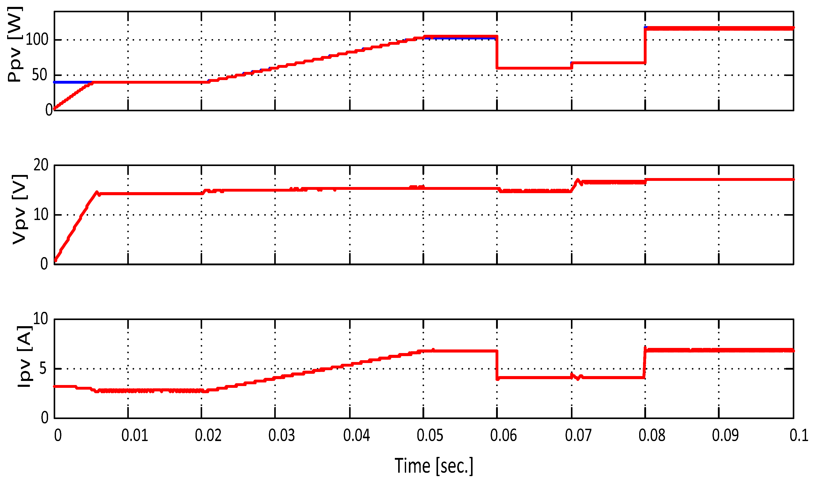
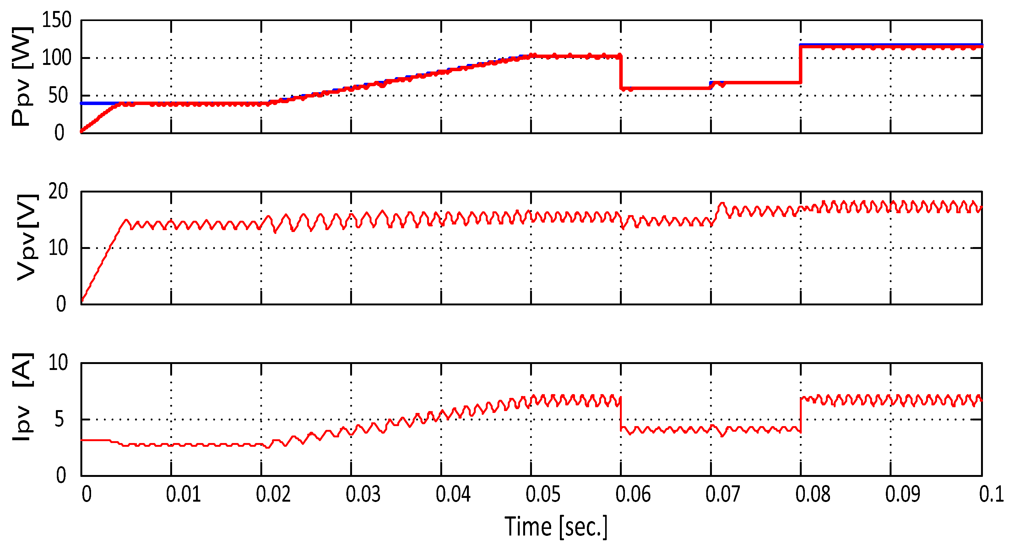
3. Simulation Results
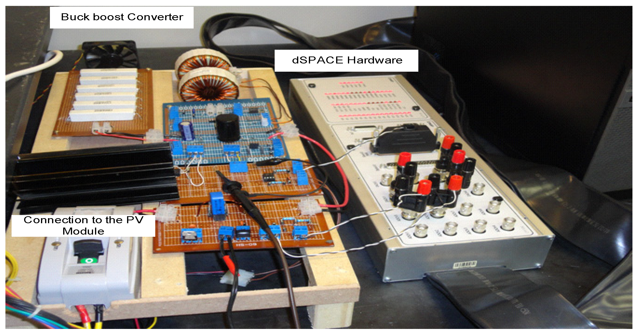
4. Experimental Setup
4.1. Case 1: Pure Resistive Load
4.2. Case 2: Dynamic Load
5. Discussion
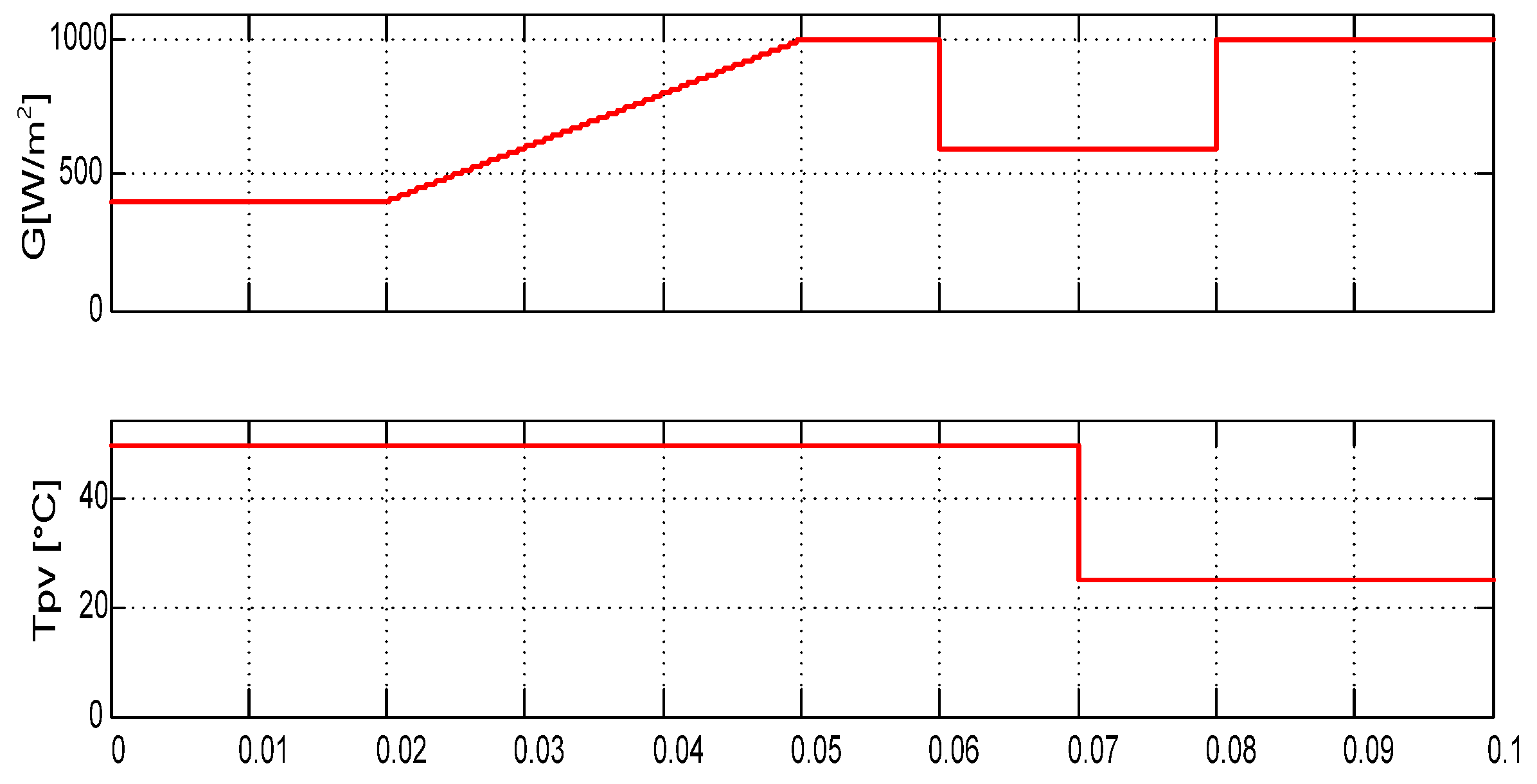
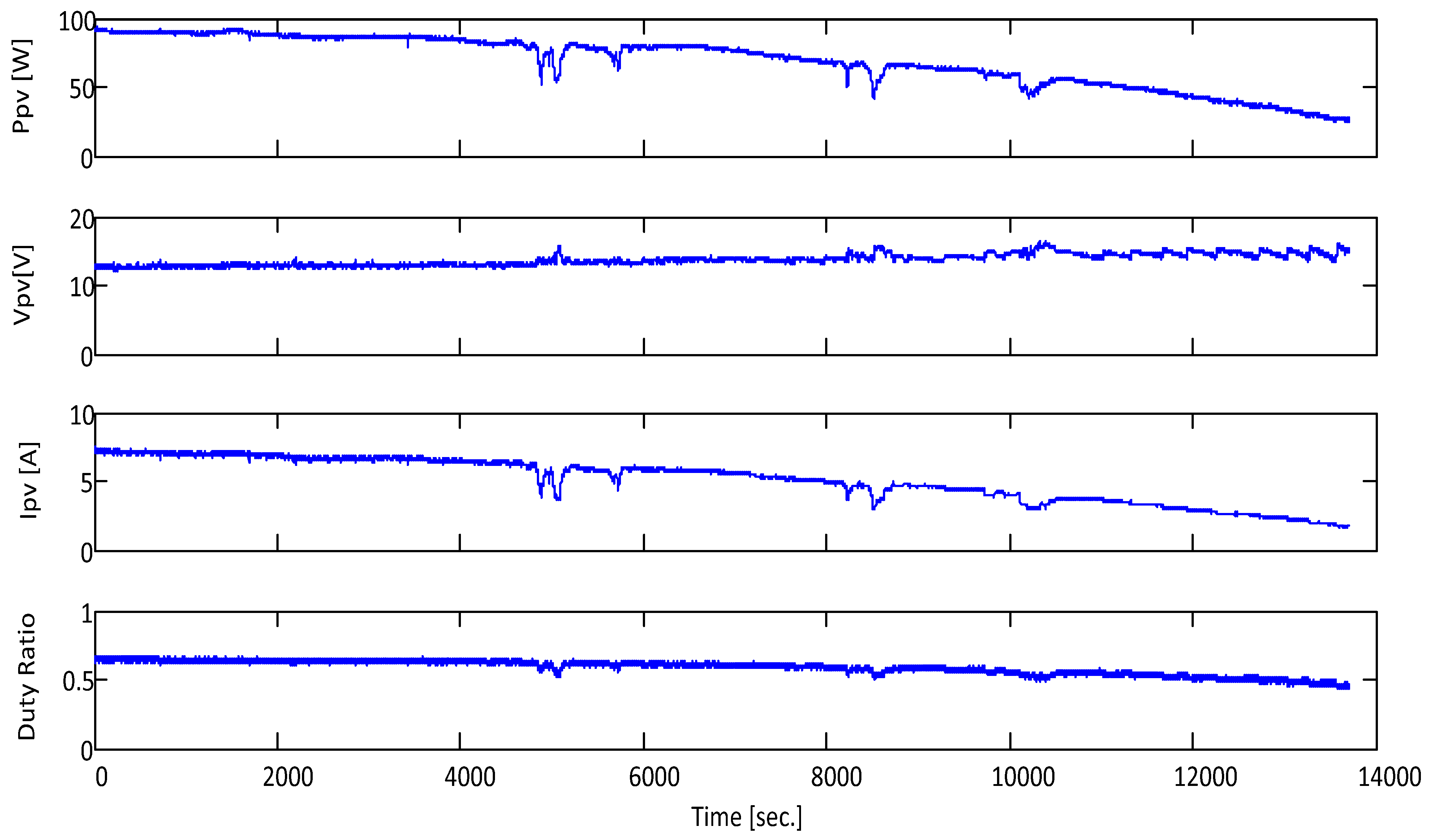
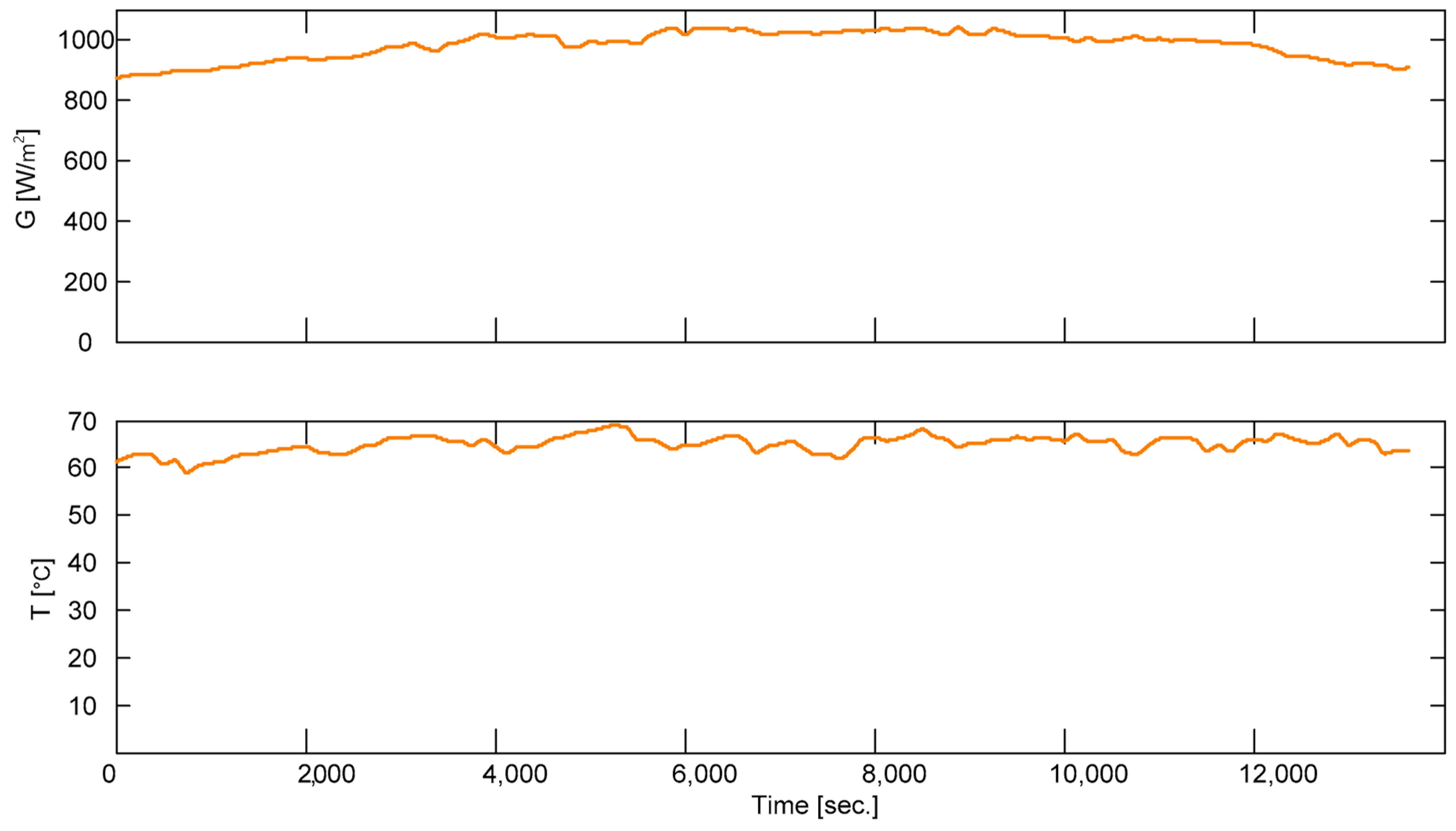
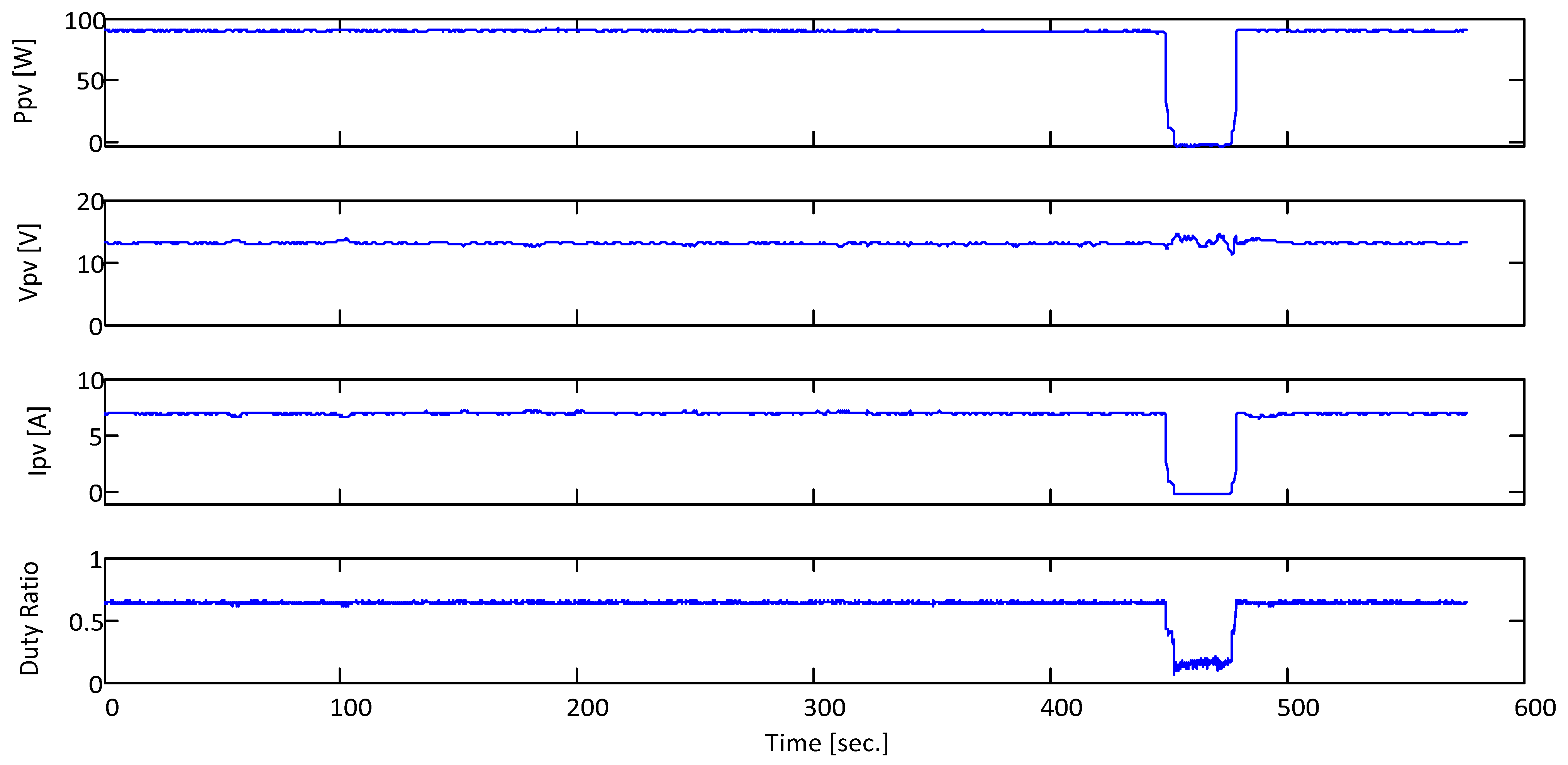
- In the first case, it is tested under a fixed resistive load for two different days, each for four hours (the measured temperature and solar radiation are seen in Figure 17 and Figure 19). In these two scenarios, the proposed MPPT accurately tracked the maximum power with low oscillations around the MPP. Moreover, it was examined under a step change in the solar radiation. To test the MPPT under a step change of solar radiation, the PV module is covered by an opaque cover and then removed. Even under this step change in the solar radiation, the proposed MPPT keeps tracking the maximum power as seen in Figure 21.
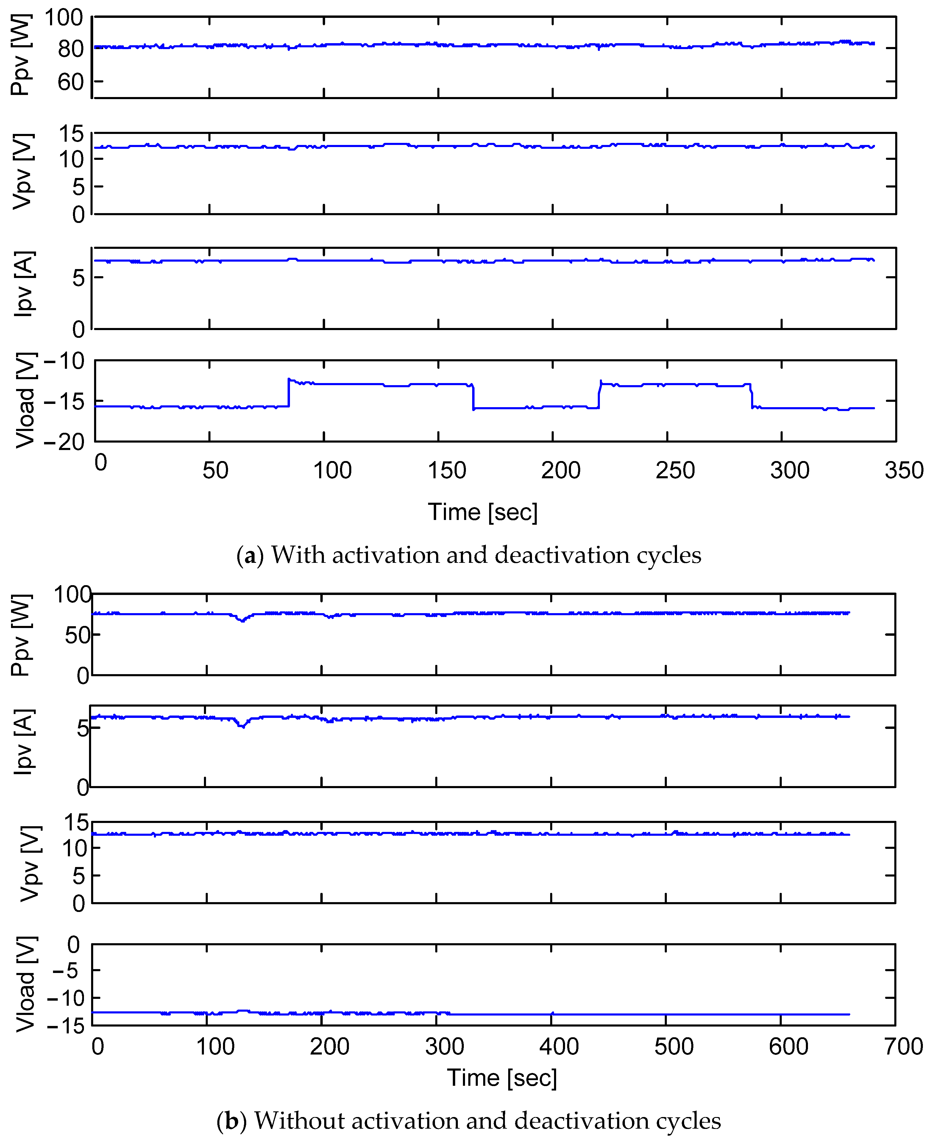
- In the second case, the MPPT is examined under load variation:
- The water pump is connected in parallel with the fixed resistive load. That is, the load is a dynamic load. The water pump is connected and disconnected many times as seen in Figure 22a. The proposed MPPT keeps tracking the maximum power point, while the load voltage is changed due to the loading variation.
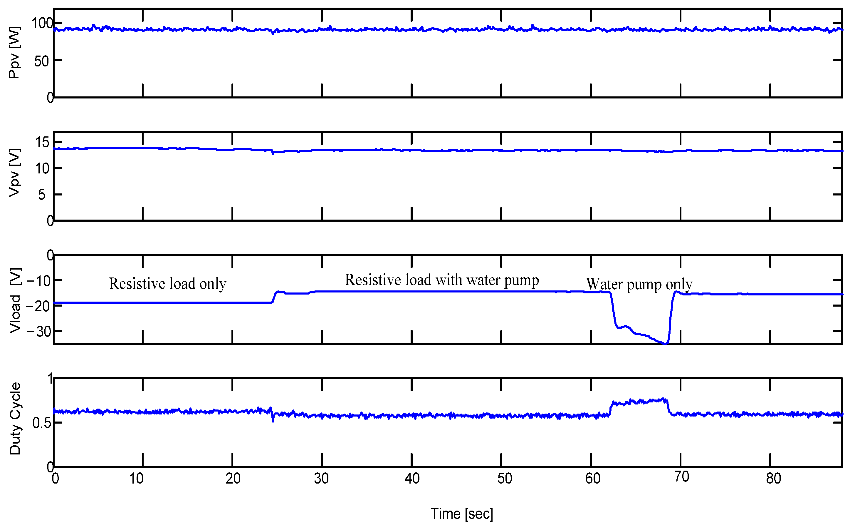
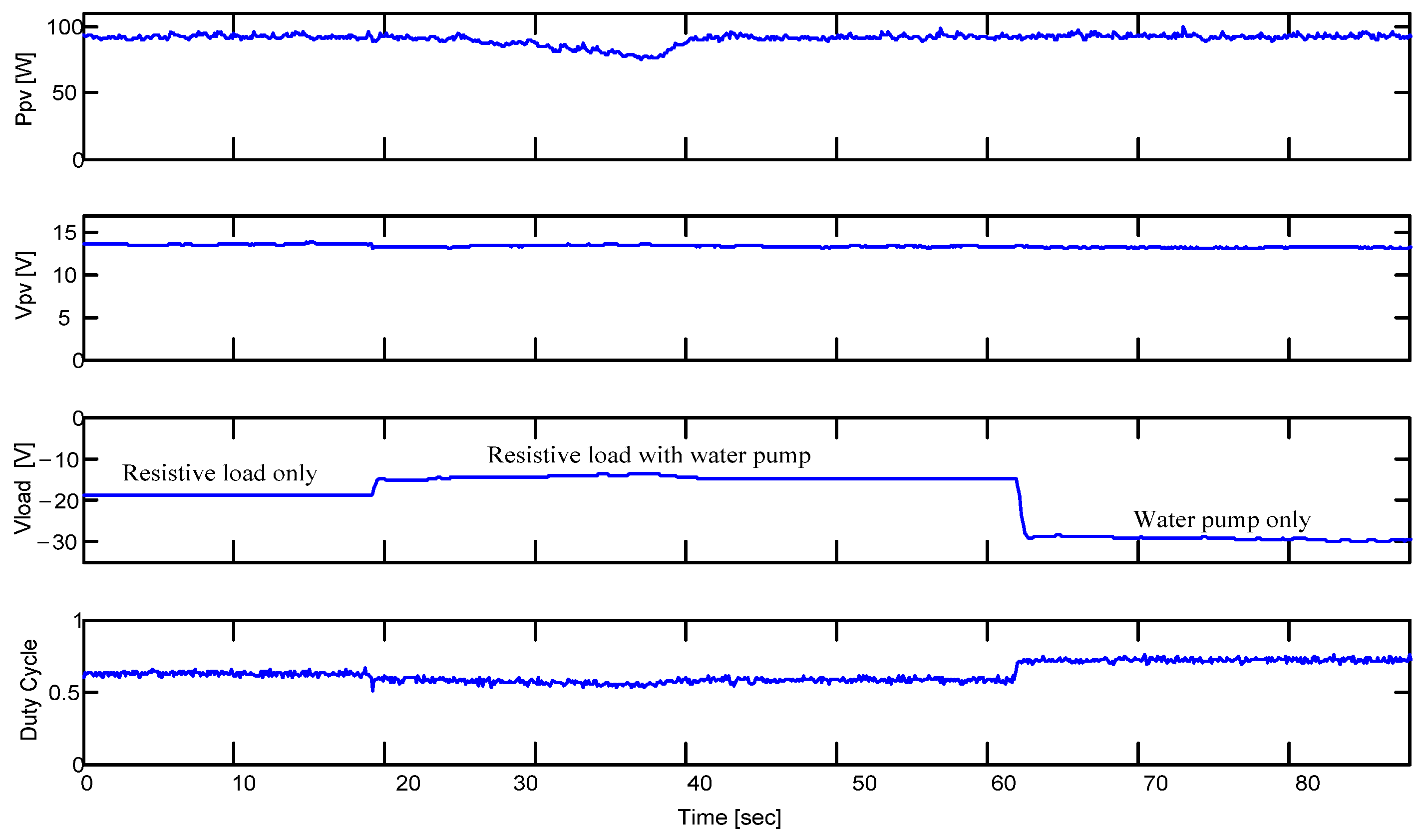
- Moreover, the proposed MPPT is tested under different loading conditions in which the resistive load is only connected, then the motor is connected in parallel with the resistive load, and finally the resistive load is isolated. Figure 23 shows the robustness of the proposed MPPT algorithm under this hard loading variation.
6. Conclusions
Author Contributions
Funding
Data Availability Statement
Conflicts of Interest
References
- Sovacool, B.K.; Schmid, P.; Stirling, A.; Walter, G.; MacKerron, G. Differences in carbon emissions reduction between countries pursuing renewable electricity versus nuclear power. Nat. Energy 2020, 5, 928–935. [Google Scholar] [CrossRef]
- De Martin, I.D.; Pasqualotto, D.; Tinazzi, F.; Zigliotto, M. Model-Free Predictive Current Control of Synchronous Reluctance Motor Drives for Pump Applications. Machines 2021, 9, 217. [Google Scholar] [CrossRef]
- Bhukya, L.; Kedika, N.R.; Salkuti, S.R. Enhanced maximum power point techniques for solar photovoltaic system under uniform insolation and partial shading conditions: A review. Algorithms 2022, 15, 365. [Google Scholar] [CrossRef]
- Omotoso, H.O.; Al-Shamma’a, A.A.; Farh, H.M.; Noman, A.M.; Alkuhayli, A.A. Parameter extraction of solar photovoltaic modules using Manta Ray Foraging Optimization (MRFO) Algorithm. In Proceedings of the 2022 IEEE 16th International Conference on Compatibility, Power Electronics, and Power Engineering (CPE-POWERENG), Birmingham, UK, 29 June–1 July 2022; IEEE: Piscataway, NJ, USA, 2022; pp. 1–6. [Google Scholar]
- A. Alturki, F.; Al-Shamma’a, A.A.; M. H. Farh, H. Simulations and dSPACE real-time implementation of photovoltaic global maximum power extraction under partial shading. Sustainability 2020, 12, 3652. [Google Scholar] [CrossRef]
- Abidi, H.; Sidhom, L.; Chihi, I. Systematic Literature Review and Benchmarking for Photovoltaic MPPT Techniques. Energies 2023, 16, 3509. [Google Scholar] [CrossRef]
- Zaky, A.A.; Sergeant, P.; Stathatos, E.; Falaras, P.; Ibrahim, M.N. Employing Dye-Sensitized Solar Arrays and Synchronous Reluctance Motors to Improve the Total Cost and Energy Efficiency of Solar Water-Pumping Systems. Machines 2022, 10, 882. [Google Scholar] [CrossRef]
- Yañez-Badillo, H.; Beltran-Carbajal, F.; Rivas-Cambero, I.; Favela-Contreras, A.; Arroyo-Nuñez, J.H.; Balderas-Gutierrez, J.N. Enhanced Output Tracking Control for Direct Current Electric Motor Systems Using Bio-Inspired Optimization. Machines 2023, 11, 1006. [Google Scholar] [CrossRef]
- Latifi, M.; Abbassi, R.; Jerbi, H.; Ohshima, K. Improved krill herd algorithm based sliding mode MPPT controller for variable step size P&O method in PV system under simultaneous change of irradiance and temperature. J. Frankl. Inst. 2021, 358, 3491–3511. [Google Scholar]
- Rezk, H.; Aly, M.; Ghoniem, R.M. Robust Fuzzy Logic MPPT Using Gradient-Based Optimization for PEMFC Power System. Sustainability 2023, 15, 13368. [Google Scholar] [CrossRef]
- Giurgi, G.I.; Szolga, L.A.; Giurgi, D.V. Benefits of fuzzy logic on MPPT and PI controllers in the chain of photovoltaic control systems. Appl. Sci. 2022, 12, 2318. [Google Scholar] [CrossRef]
- Castillo, O.; Amador-Angulo, L.; Castro, J.R.; Garcia-Valdez, M. A comparative study of type-1 fuzzy logic systems, interval type-2 fuzzy logic systems and generalized type-2 fuzzy logic systems in control problems. Inf. Sci. 2016, 354, 257–274. [Google Scholar] [CrossRef]
- Cervantes, L.; Castillo, O. Type-2 fuzzy logic aggregation of multiple fuzzy controllers for airplane flight control. Inf. Sci. 2015, 324, 247–256. [Google Scholar] [CrossRef]
- Chekired, F.; Larbes, C.; Rekioua, D.; Haddad, F. Implementation of a MPPT fuzzy controller for photovoltaic systems on FPGA circuit. Energy Procedia 2011, 6, 541–549. [Google Scholar] [CrossRef]
- Purnama, I.; Lo, Y.K.; Chiu, H.J. A fuzzy control maximum power point tracking photovoltaic system. In Proceedings of the 2011 IEEE International Conference on Fuzzy Systems (FUZZ-IEEE 2011), Taipei, Taiwan, 27–30 June 2011; IEEE: Piscataway, NJ, USA, 2011; pp. 2432–2439. [Google Scholar]
- Errouha, M.; Derouich, A.; Motahhir, S.; Zamzoum, O.; El Ouanjli, N.; El Ghzizal, A. Optimization and control of water pumping PV systems using fuzzy logic controller. Energy Rep. 2019, 5, 853–865. [Google Scholar] [CrossRef]
- Alice Hepzibah, A.; Premkumar, K. ANFIS current voltage controlled MPPT algorithm for solar powered brushless DC motor based water pump. Electr. Eng. 2020, 102, 421–435. [Google Scholar] [CrossRef]
- Darcy Gnana Jegha, A.; Subathra, M.S.P.; Manoj Kumar, N.; Subramaniam, U.; Padmanaban, S. A high gain dc-dc converter with grey wolf optimizer based MPPT algorithm for PV fed BLDC motor drive. Appl. Sci. 2020, 10, 2797. [Google Scholar] [CrossRef]
- Parimala, V.; Ganeshkumar, D.; Divya, M. Implementation of Solar Water Pumping System Using Fuzzy Logic Controller. In Proceedings of the 2020 6th International Conference on Advanced Computing and Communication Systems (ICACCS), Coimbatore, India, 6–7 March 2020; IEEE: Piscataway, NJ, USA, 2020; pp. 967–970. [Google Scholar]
- Hasan, M.; Alhazmi, W.H.; Zakri, W. A fuzzy rule based control algorithm for MPPT to drive the brushless dc motor based water pump. J. Intell. Fuzzy Syst. 2022, 42, 1003–1014. [Google Scholar] [CrossRef]
- Tha’er, O.S.; Abuashour, M.I.; Osman, N.F. Transient Analysis of DC Shunt Motor Supplied by Stand-alone PV System Employing FOCV for MPPT. In Proceedings of the 2020 Advances in Science and Engineering Technology International Conferences (ASET), Dubai, United Arab Emirates, 4 February–9 April 2020; IEEE: Piscataway, NJ, USA, 2020; pp. 1–6. [Google Scholar]
- Altimania, M.R.; Elsonbaty, N.A.; Enany, M.A.; Gamil, M.M.; Alzahrani, S.; Alraddadi, M.H.; Mosaad, M.I. Optimal Performance of Photovoltaic-Powered Water Pumping System. Mathematics 2023, 11, 731. [Google Scholar] [CrossRef]
- Villalva, M.G.; Gazoli, J.R. Modeling and circuit-based simulation of photovoltaic arrays. In Proceedings of the 2009 Brazilian Power Electronics Conference, Bonito-Mato Grosso do Sul, Brazil, 27 September–1 October 2009; pp. 1244–1254. [Google Scholar]
- Walker, G. Evaluating MPPT converter topologies using a MATLAB PV model. J. Electr. Electron. Eng. 2001, 21, 49–56. [Google Scholar]
- Kurokawa, F.; Ishibashi, T. Dynamic characteristics of digitally controlled buck-boost dc-dc converter. In Proceedings of the 2009 International Conference on Power Electronics and Drive Systems (PEDS), Taipei, Taiwan, 2–5 November 2009; IEEE: Piscataway, NJ, USA, 2009; pp. 300–303. [Google Scholar]
- Hart, D.W.; Hart, D.W. Power Electronics; McGraw-Hill: New York, NY, USA, 2011; Volume 166. [Google Scholar]
- Mohan, N.; Undeland, T.M.; Robbins, W.P. Power Electronics: Converters, Applications, and Design; John Wiley & Sons: Hoboken, NJ, USA, 2003. [Google Scholar]
- Narwat, L.K.; Dhillon, J. Design and operation of fuzzy logic based MPPT controller under uncertain condition. J. Phys. Conf. Ser. 2021, 1854, 012035. [Google Scholar] [CrossRef]
- Thaker, S.; Nagori, V. Analysis of fuzzification process in fuzzy expert system. Procedia Comput. Sci. 2018, 132, 1308–1316. [Google Scholar] [CrossRef]


| Parameters | Value |
|---|---|
| Maximum Power (Pmax) | 115 W |
| Voltage at Pmax (Vmp) | 17.1 V |
| Current at Pmax (Imp) | 6.7 A |
| Open Circuit Voltage (Voc) | 21.8 V |
| Short Circuit Current (Isc) | 7.5 A |
| Temperature Coefficient of Isc | 0.065 ± 0.015%/°C |
| Buck-Boost Converter Parameters | |
|---|---|
| Inductor L | 1 mH |
| Input Capacitor C1 | 1000 |
| Output Capacitor C2 | 330 |
| Switching frequency | 40 kHz |
| Resistive Load | 5 Ω |
| MOSFET Type: IRF3710 Diode Type: BYV32-200 | |
| Components Used in the Experimental Setup | |
| Controller Type: dSPACE 1104 DSP | |
| Current Transducer | LTS 25-NP |
| Voltage Divider | Two 120 KΩ and 39 KΩ resistors are connected in series. The voltage is taken across the 39 KΩ resistor. |
| NB | NS | Z | PS | PB | ||
|---|---|---|---|---|---|---|
| NB | NB | NB | Z | NS | NS | |
| NS | NS | NS | Z | NS | NB | |
| Z | NB | NS | Z | PB | PB | |
| PS | NB | NB | Z | PB | PB | |
| PB | PB | PB | Z | Z | Z | |
Disclaimer/Publisher’s Note: The statements, opinions and data contained in all publications are solely those of the individual author(s) and contributor(s) and not of MDPI and/or the editor(s). MDPI and/or the editor(s) disclaim responsibility for any injury to people or property resulting from any ideas, methods, instructions or products referred to in the content. |
© 2024 by the authors. Licensee MDPI, Basel, Switzerland. This article is an open access article distributed under the terms and conditions of the Creative Commons Attribution (CC BY) license (https://creativecommons.org/licenses/by/4.0/).
Share and Cite
Alkuhayli, A.; Noman, A.M.; Al-Shamma’a, A.A.; Abdurraqeeb, A.M.; Alharbi, M.; Hussein Farh, H.M.; Qamar, A. Enhancing Photovoltaic-Powered DC Shunt Motor Performance for Water Pumping through Fuzzy Logic Optimization. Machines 2024, 12, 442. https://doi.org/10.3390/machines12070442
Alkuhayli A, Noman AM, Al-Shamma’a AA, Abdurraqeeb AM, Alharbi M, Hussein Farh HM, Qamar A. Enhancing Photovoltaic-Powered DC Shunt Motor Performance for Water Pumping through Fuzzy Logic Optimization. Machines. 2024; 12(7):442. https://doi.org/10.3390/machines12070442
Chicago/Turabian StyleAlkuhayli, Abdulaziz, Abdullah M. Noman, Abdullrahman A. Al-Shamma’a, Akram M. Abdurraqeeb, Mohammed Alharbi, Hassan M. Hussein Farh, and Affaq Qamar. 2024. "Enhancing Photovoltaic-Powered DC Shunt Motor Performance for Water Pumping through Fuzzy Logic Optimization" Machines 12, no. 7: 442. https://doi.org/10.3390/machines12070442
APA StyleAlkuhayli, A., Noman, A. M., Al-Shamma’a, A. A., Abdurraqeeb, A. M., Alharbi, M., Hussein Farh, H. M., & Qamar, A. (2024). Enhancing Photovoltaic-Powered DC Shunt Motor Performance for Water Pumping through Fuzzy Logic Optimization. Machines, 12(7), 442. https://doi.org/10.3390/machines12070442