Abstract
This review paper is an homage to Arvid Palmgren’s pioneering paper on rolling bearing service life to highlight its relevance a century later. It follows the evolution of bearing service life theory from Palmgren’s fundamental research to the contemporary international standard ISO 281. Palmgren’s theory, based on the previously published papers of Stribeck and Hertz, laid the basis for the later development of bearing service life assessment methodology. Based on the Weibull theory of probability of damage, Lundberg and Palmgren introduced stochastic elements to explain the effect of reliability on bearing service life prediction. Harris and Ioannides, who made a significant contribution to the revision of the international standard on rolling bearing load rating and rating life are mentioned as well. Zaretsky’s critical analysis also was not neglected in this review, due to a different approach respecting the original influence of material properties and bearing performances. Despite standardization, ongoing research by leading advanced bearing industries and academic institutions continues to refine methodologies for service life assessment. Through a comprehensive review and analysis, this paper offers insight into the current state of bearing service life theory, highlighting the collaborative efforts bringing progress in this field.
1. Introduction
This review paper is a tribute to Arvid Palmgren’s paper on the service life of ball bearings, published in 1924 [1]. The genius of Palmgren’s bearing life theory is reflected in the fact that it is still relevant today, even though it was created exactly a century ago. The theory of rolling bearing service life initiated in [1], with certain changes and additions, is still today the basis of the calculation procedure for estimating the rating life of rolling bearings. The procedure for determining the rating life of rolling bearings is standardized. It is significant in the design, manufacture, distribution, and application of rolling bearings. Adherence to the same international standards globally ensures that the results of research work and construction projects are comparable and adequately evaluated. By respecting and applying standards, every such work gains an international character, starting from size designations and term definitions, through geometric parameters and various forms of calculations, to equipment and test procedures, data acquisition, and analysis of results. Hence, this paper describes the evolution of the standard for calculating the dynamic load ratings and rating life of rolling bearings [2].
The professional and scientific community should be grateful to the creators of standards in the field of rolling bearings as well as to the experts who were or are currently involved today in the development of international ISO standards in this field. Their significant efforts have resulted in a high level of organization in the standard method of calculating the service life of rolling bearings more than in the case of any other machine element.
The theory of rolling bearing service life has been evolving for a century, undergoing changes from its foundational concepts to the present day. Among the key figures are Tedrik Harris and Statis Ioannides, whose research led to significant revisions in the ISO 281 standard for calculating dynamic load capacity and service life, published in 2007 [2]. Ervin Zaretsky emerges as a prominent critic of the established and standardized model for bearing service life. Given the substantial contributions of these researchers to the theory of bearing life, a portion of this article is dedicated to examining their work.
2. General Considerations
In the process of designing bearing arrangements, the engineer does not construct rolling bearings or create drawing documentation for their production. Rolling bearings are instead purchased as complete sub-assemblies from the market, selected for specific applications based on certain criteria. The selection of rolling bearings is dependent on various factors, including the shaft sleeve diameter and available space in the housing, the load intensity and direction (radial, axial, or combined—universal as it is named in appropriate international standards), shaft inclination in the supports, rotational speed, lubricant type and method of lubrication (such as circulating oil with or without filtering, oil bath, periodic grease refill, or permanent grease lubrication), environment temperature, contamination (such as mineral particles, wear products from other machine parts, water, steam, other liquids, mists, or vapors), and the required service life with a certain level of reliability. Unlike many machine elements and parts, where load capacity and operational ability are evaluated by determining safety factors, rolling bearings are assessed for their service life. Similar to safety factors, which express the ratio of critical to operating loads of machine parts, the service life of a bearing is represented by the ratio of a critical quantity (dynamic load rating C) to a working quantity (equivalent bearing load P), raised to an exponent p. This exponent’s value depends on the bearing’s rolling element shape (p = 3 for ball bearings; p = 10/3 for roller bearings). For specific, known operating conditions regarding lubrication, filtration, contamination, and reliabilities other than 90%, the basic service life of the bearing should be adjusted using appropriate factors (a1 for reliability and aISO for operating conditions):
This is a standardized expression for the rolling bearings’ service life, currently accepted and authoritative in bearing production, industrial exploitation, and engineering education within the field of machine elements and systems. To determine the service life of a bearing in practice, i.e., to apply the formula for service life, it is necessary to know the parameters of the operating conditions and have bearing data. All quantities in the service-life expression are derived from this data, typically presented in appropriate tables and/or diagrams in bearing manufacturers’ catalogs. The calculation is reduced to a minimum and is used only for the simple determination of the equivalent load P and the rating life L itself. However, the “path to” a simple form and the application of the bearing-life formula “is paved with” complex multi-disciplinary theory, verified by a million experimental tests and theoretical analyses. This theory “was born” almost a hundred years ago and is still relevant, but also under further development and improvement.
Rolling bearings were industrially produced in specialized factories many years before the occurrence of the theory of their service life. During that period, each bearing manufacturing factory, in its own way, probably mostly empirically, assessed the load capacity and durability of their products. To obtain the most accurate representations of bearing load rating and service life across their entire product range, extensive testing with a large number of samples was necessary. However, managing such tests was expensive and time-consuming. Therefore, the rolling-bearing industry needed a unified procedure for calculating bearing load capacity and estimating service life to make possible product comparisons, ensure quality assurance in the market, and establish credibility with users. The concept of developing a mathematical model for the rolling bearing service life was originated by Arvid Palmgren, an inventive and dedicated engineer and scientist, who worked at the Swedish rolling bearing factory SKF.
Palmgren published his first statements on determining the equivalent load and service life of ball rolling bearings in 1924 [1]. These statements are based on Stribeck’s theory of load distribution between rolling elements, and Hertz’s theory of contact deformations. In 1947, Palmgren and Lundberg published a paper where the calculation of the bearing service life includes reliability, stresses caused by the external bearing load, the number of stress cycles, the volume affected by the stresses, and the length of the raceways [3]. Five years later, the same authors published a paper [4] in which they derived the expressions for the equivalent load, dynamic load rating, and rating life of the bearing, in the form we know today. The expression is based on Sjövall’s mathematical model of load distribution between rolling elements and Weibull’s theory of probability distribution of fatigue damage.
During the development of the theory of rolling bearing service life, the international standard ISO 281 was established for calculating the dynamic load rating and rating life of the rolling bearing. The initial standard recommendations, based on the Lundberg–Palmgren formula, were published in 1962. These recommendations provided a relatively simple calculation procedure that was used by both bearing manufacturers and users installing bearings in machines. However, this was only the beginning of the development of the standard life formula. As the design and technology of rolling bearings had been developing, both manufacturers and users recognized weak points in the expression for the basic service life. Calculated values often deviate from actual values under specific operating conditions. Consequently, the basic formula for service life went through revisions by incorporating new adjustment factors, leading to changes in the official versions of the ISO 281 standard. Thus, the International Organization for Standardization (ISO) became the official witness and chronicler of the development of the theory of bearing service life.
The ISO 281 standard itself is not extensive. It contains basic expressions for dynamic load ratings and auxiliary tables for its determination, instructions for determining the equivalent load of the bearing, based on support reactions, appropriate tables for determining the equivalence factors, and, finally, the expressions themselves for the basic and modified rating life of the bearing. Along with the very concise content of the standard, supplementary ISO documents (two technical reports and one technical specification) also have been published. The technical reports contain clarifications regarding the derivation of the expressions for the rating life and the life modified by the appropriate factors. Those technical reports are concise considerations from the theory of rolling bearing life. The technical specification is a document of very limited content, indicating that the current expression for the bearing service life is not comprehensive and that there are still some influences that have not been taken into account so far. The life formula was significantly modified in 2000, with the introduction of a systems-approach factor to life calculation, which takes into account the complex conditions of lubrication, contamination, and fatigue load limit. This extension of the expression with an appropriate modification factor and the whole procedure of determining this factor was carried out based on the theory of Ioannides and Harris [5].
3. Life Theory Was Born
The rolling bearing service life is calculated based on the expression developed by Lundberg and Palmgren. Their theory of rolling bearing service life is founded on three main principles or “pillars”, as illustrated in Figure 1. These are the theory of contact deformations by Hermann Hertz, the theories of load distribution between rolling elements by Richard Stribeck and Harald Sjövall, and the stochastic theory of Waloddi Weibull.

Figure 1.
Foundation and three pillars of the rolling bearing life theory.
The first significant studies on rolling bearings service life were carried out by Arvid Palmgren. Although Palmgren began his research several years earlier, a paper on the service life of ball bearings, published in 1924, is considered the historical beginning of the development of the rolling-bearing-life formula. The study was based on the results of experimental research at the bearing factory SKF and mathematical descriptions of the observed phenomena. In the paper [1], Palmgren refers to his previously published papers. It is a paper from 1919, about the results of his experimental research on the load-carrying capacity of ball rolling bearings [6] as well as a paper from 1923 about theoretical and practical methods of calculating the bearing load carrying capacity [7]. Palmgren based his theory of service life on earlier studies and theories of other authors. It is the first theory of load distribution between rolling elements in the bearing of Stribeck, published in 1901 and 1902 [8], as well as Hertz’s theory of the elastic bodies contact [9] published in 1881. So, it can be stated that the foundations of the theory of bearing service life were laid at the end of the XIX century.
Thirty years after Stribeck’s mathematical model of load distribution between rolling elements in bearing, a new approach was introduced by Sjövall [10]. Sjövall started from the assumption that there is a large number of rolling elements in the bearing (which tend to infinity) and small diameters (which tend to zero). He replaced the sums from Stribeck’s model with integrals, and then further developed his theory of load distribution so that it could be applied in the calculation of the equivalent load, bearing dynamic rating, and rating life. This method is approximate, but during decades of studying the load distribution in rolling bearings, it has proven to be accurate enough for service life estimation and to analyze its influence on some other phenomena [11,12]. From the very beginning of his experimental and theoretical research on bearing service life, Palmgren highlighted the problem of service-life dissipation and the problem of reliability. Following the publication of Weibull’s theory on the distribution of the probability of failure in 1939 [13], Lundberg and Palmgren, developed and published expressions for rolling bearing service life, in 1947 and 1952. These expressions were based on Weibull’s stochastic approach to estimating the probability of fatigue failure. The fundamental expression for rolling bearing service life was established and validated by the scientific and professional community, maintaining the same mathematical form that we continue to use today. This expression was officially standardized in 1962.
4. The Paper “Die Lebensdauer von Kugellagern” by N.A. Palmgren [1]
This paper marks the historical beginning of the development of the rolling bearing life theory. Titled “Life of Ball Bearings”, it was written in German and published in 1924 in the journal “Zeitschrift des Vereines Deutscher Ingenieure,” by VDI (Figure 2). It consists of three pages and cites six references, including two self-citations by Palmgren (papers from 1919 [6] and 1923 [7]). Both of Palmgren’s cited papers focus on researching theoretical and practical methods for calculating the load rating of ball bearings. In his paper, Palmgren also references Stribeck’s study [8] on load distribution in rolling bearings as well as Hertz’s posthumously published paper on the contact of elastic bodies [9].
Figure 2.
Journal VDI—Zeitschrift des Vereines Deutscher Ingenieure, Vol.68, №14, 1924.
In the introduction, Palmgren states and explains a significant and enduring fact, relevant even today: that the dynamic durability and service life of a rolling bearing cannot be accurately determined based solely on testing material specimens or using conventional expressions for determining dynamic durability. He states that the relevant results can only be obtained by testing a large number of complete assemblies of rolling bearings. Only after a large number of tests have been performed can one approach the derivation of analytical expressions, which would be in agreement with the results of experimental research.
Rolling bearings are complex machine assemblies, each part of this assembly has dynamic strength, both volumetric and surface, defined and determined according to conventional fatigue theories. However, the rolling bearing, as an assembly of complex construction, kinematics, dynamics, and tribology, requires a completely different approach to determining dynamic durability, i.e., dynamic load capacity and service life. Palmgren’s practical experience shows that the stresses that occur in individual parts of the bearing can exceed their dynamic strengths and that the bearing as a whole will have a fully satisfactory load capacity for a given, limited, service life as well as for other techno-economic parameters (optimal geometry, mass, processing technologies, etc.).
Palmgren briefly referred to Hertz’s theory of the contact of elastic bodies. He states that expressions for contact pressures are derived based on a series of highly simplified assumptions, leading to inaccuracies in determining contact deformations. Palmgren refers to the results of his previous research [3,4], which revealed a divergence between experimental results and contact pressures analytically determined using Hertz’s theory. For this reason, Hertz’s theory initially did not receive enough attention from the rolling bearing industry at the time. Initially, Palmgren had doubts about the Hertz equations, which determine contact stresses in rolling elements and bearing raceways [14]. However, he later eliminated these doubts. In the papers [3,4], it is stated that Hertz’s theory is valid under the assumption that the contact area is significantly smaller than the dimensions of the rolling elements, allowing frictional forces on the contact surfaces to be neglected. Furthermore, Hertz’s equations are correct and confirmed in the case of ball bearings with very close ball and raceway radii. In the case of roller bearings, there are certain deviations, i.e., limitations of the validity of Hertz’s theory, due to the stress concentration at the contact between rollers’ edges and raceways.
In [3,4], Lundberg and Palmgren state that at that time it was still unknown how the material reacts to shear stresses in contact, what is the influence of residual stresses, how the lubricant affects the stress distribution on the contact surface, and what occurs in the case of expansion of the inner ring during installation on the sleeve or contraction of the outer ring during installation in the housing. In the theory of rolling bearings, some of these phenomena are partially or completely explained, so they are taken into account in calculating the load capacity and service life of the bearing [14]. Palmgren stated that the subject of the paper [4] was the development of a procedure for calculating rolling bearings, with three primary goals: establishing the service-life function of a radially loaded ball bearing; establishing rules for reducing combined radial and axial loads, or pure axial loads, into an equivalent radial load used for calculating service life; and, finally, providing a mathematical description of the effect of loads that change stepwise during the bearing’s life.
4.1. Life Function
Palmgren began with the assumption that the materials of the bearing parts in contact have a fatigue limit in the traditional sense (dynamic durability), meaning they can endure an unlimited number of load cycles at a certain variable stress. Therefore, the curve of the bearing service life must be asymptotic. Additionally, it should be noted that these materials have their mechanical properties, including limits of elasticity, plasticity, and tensile strength, implying that the curve must also have a final limit load for one load cycle. Palmgren’s assumed exponential function for the relationship between load and the number of cycles takes the following form:
where k is the specific load of the bearing in kg/(1/8″)2; C is a material constant; n is the rotation speed; a is the number of load cycles of the most heavily loaded point in the bearing, during one revolution of the rotating ring; e is a material constant, which depends on the limits of elasticity or fracture; u is the fatigue limit; and x is an exponent.
Palmgren introduced the e constant in expression (2) as a material characteristic, assuming that material properties influence the bearing service life. The constant e is a dimensionless quantity added to the product of the quantities n and a, which represents the number of load cycles. However, in this paper, Palmgren’s intended meaning remains unclear. Only later, in [3,4], Palmgren and Lundberg defined the quantity e as the number of load cycles at which damage is not expected. To determine the constants C and e, Palmgren proposed experimental tests requiring a large number of tested bearing units subjected to different load values. He noted that extensive experiments have been conducted at the bearing-manufacturer site and warned about the dispersion of the obtained results and reliability issues. It is further stated that one should accept the fact that of all the bearings tested or installed in machine systems, a relatively small number will not reach the expected service life, calculated by the proposed mathematical model. Accordingly, after analyzing the test results, he determined that the constants C and e were determined with a reliability of 90%. This implies that 90% of bearings will achieve the service life determined by the proposed model, with the remaining 10% failing before the intended service life ends. In this paper, Palmgren also provides expressions for determining the fatigue limits of ball bearings. However, Palmgren highlights that these results and derived expressions are not universal, as they depend on the quality of materials used in bearing manufacturing. While the validity of the formulas was confirmed through testing bearings of certain manufacturers, results may vary for bearings from other manufacturers depending on applied materials and heat treatment [1]. The exponent x is in the range from 0.30 to 1/3 according to Palmgren’s experimental results.
Palmgren described the specific load k in the expression (2) as the stress in the most heavily loaded contact between balls and raceways, and for its determination, he used Stribeck’s formula [1]:
where Q is the equivalent bearing load; Z is the number of balls in bearing; and d is the balls’ diameter.
Palmgren was not completely satisfied with Stribeck’s expression (3) because it does not take into account the effects of the rotational speed and the bearing size. That is why in the paper [1] he proposed a corrected expression, which in his opinion was in better correlation with the experimental results. However, he did not use that expression in [3,4], which represents the basis of the development of the current theory of bearing service life.
4.2. Equivalent Radial Load
Referring to his articles from 1919 and 1923, as well as the results of carried-out tests, Palmgren notes that the combined radial and axial bearing loads can be reduced to a single, equivalent, radial load, which has the same effect on the service life as well as the combined radial-axial load, using a very simple formula:
where R is the radial load of the bearing (radial reaction in fixed support); A is the axial load of the bearing (axial reaction in fixed support); and y is the coefficient of the reduction of the axial load A to the supplementary radial, which with the radial load R gives the equivalent load of the bearing, relevant for the service-life calculation.
The y constant in (4) is determined experimentally, by bearing testing, and has a value from 0.9 to 1.5, depending on the contact angle between the balls and raceways, i.e., from bearing type and its internal design [1]. Many years later, in papers [3,4], Lundberg and Palmgren gave an expression for the equivalent load, which is still used today:
where Fr is the bearing radial load (radial component of actual bearing load); Fa is the bearing axial load (axial component of actual bearing load); X is the dynamic radial load factor; and Y is the dynamic axial load factor.
To determine the number of load cycles at the most stressed point in the bearing, it is necessary to first identify that point. This point, under a constant bearing load, typically lies on one of the raceways, depending on the bearing type and on which ring is rotating. Assuming the balls are of exceptionally high quality in terms of materials and mechanical and thermal treatments, the number of load cycles at the most stressed point during one revolution of the rotating ring a in (2) depends on the number of rolling elements—balls passing over that point on the raceways. The product of a and the bearing rotational speed n is the total number of load cycles at the most stressed point in the bearing, effectively representing the bearing service life in terms of load cycles. Palmgren in [1] did not derive an expression for bearing service life. However, in line with the aforementioned discussion, one can obtain an expression for the service life as a function of material characteristics and specific load by the following transforming expression (2):
In [3,4], the authors rejected the concept of the fatigue limit (u = 0) and instead proposed that the constant e represents a finite time during which fatigue damage is not expected. Thus, it can be assumed that e equals zero [14]. Based on these assumptions, and considering the previously mentioned exponent x as 1/3 (i.e., 1/x = 3), expression (6) takes the following form:
The product of the material constant, the number of balls in the bearing, and the square of the diameter of the balls in expression (7) is a characteristic of each bearing, depending on the type and size. This product represents the “first version” of the expression for the radial dynamic load rating Cr [14]. If the product an, which represents the total number of load cycles of the most heavily loaded point in the bearing, is denoted by the standard symbol for service life L, then the expression (7) can be written as follows:
The implemented mathematical transformations, along with appropriate assumptions and experimentally determined constants, show that the Lundberg–Palmgren formula for calculating the service life of a ball bearing, which is still in use today, is implicitly contained in Palmgren’s study from 1924!
4.3. Variable Load
In practice, it is common for the load and the bearing rotational speed to change during its service life, complicating the accurate estimation of service life. Palmgren proposes the following hypothesis: if a bearing, under a certain constant load, undergoes m1 million revolutions and has a service life of n1 million revolutions (the critical number of cycles until the appearance of a critical fatigue load), and subsequently, under another constant load, undergoes m2 million revolutions with a service life of n2 million revolutions, and so forth until the final interval of constant load, then it can be expressed as follows:
Palmgren did not further develop his hypothesis and this expression in this study. The paper ended with the conclusion that a mathematically simple and easy-to-apply function between service life and bearing load was successfully established and that this gives the possibility of accurate and reliable service-life prediction as well as the selection of bearing dimensions for a specific application.
Palmgren’s formulas are largely empirical, relying on intuition, experimental observations, analogies, and numerical approximations of experimentally obtained curves [14]. Although he initially lacked confidence in Hertz’s theory, Palmgren indirectly applied it through the Stribeck equation. His theory is based on the surface fatigue of raceways and the assumption that each material has a certain fatigue limit. It was a phenomenon he observed during many years of experimental research. However, twenty years later, in papers [3,4], he disavowed the concept of the fatigue limit. Despite this, Palmgren was a visionary, arguably the most significant figure in the field of rolling-bearing technology from the early twentieth century. Through his work, he laid the foundations and made a substantial contribution to the development of the rolling bearing life theory, which remains relevant to this day. Furthermore, Palmgren’s hypothesis regarding the accumulation of fatigue damage under variable workloads is also applicable to other machine elements and parts subjected to such kinds of loads.
5. ISO
The ISO, the International Organization for Standardization, is an independent non-governmental international organization responsible for developing and publishing international standards. Established in 1947, the ISO has published 25,309 standards to date, covering nearly all aspects of contemporary technologies, products, and businesses. It operates as a global network comprising official national standardization bodies, with 170 members representing member countries. Standard development is overseen by 832 committees and subcommittees with international membership. The organization employs 187 administrative staff at the ISO Central Secretariat, located in Geneva, Switzerland.
5.1. History
The International Federation of National Standardizing Associations (ISA), originally founded in Prague in 1928, disclaimed its operations in 1942 due to the Second World War. Following the war, the Federation was joined by the newly established United Nations Standards Coordinating Committee (UNSCC), which proposed the formation of a new global standards organization. The decision to establish the International Organization for Standardization (ISO) was reached in October 1946 during a meeting in London, where representatives from 25 member countries of ISA and UNSCC gathered to discuss the necessity and future of international standardization across various technological fields and products. The founders resolved that the future organization must be open to every country worldwide wishing to cooperate, with equal rights and responsibilities.
The first General Assembly of ISO was held in Paris in 1947, marking the official establishment and operation of the ISO through 67 technical committees. With the advent of international standardization, a new epoch in global technological advancement started. During the inaugural meeting, delegates decided to establish the ISO’s headquarters in Switzerland. The first ISO office was established in 1949, located in a private residence in Geneva, having five full-time staff members. The first ISO standard was issued in 1951. At that time, standards were referred to as Recommendations and had the additional designation “R”. The first ISO international recommendation, ISO/R1:1951, was about reference temperatures for measuring length in industry. This Recommendation has undergone numerous revisions and updates and is now known as the current standard ISO 1:2022, titled “Geometric Product Specifications (GPS)—Standard reference temperatures for geometric product specification”. In 1955, ISO members gathered for the third time at the General Assembly in Stockholm. By this point, the ISO had 35 members and had published 68 standards in the form of Recommendations. Subsequently, the ISO experienced significant growth and development, nearly doubling its membership to date, with the number of published standards exceeding 25,000.
5.2. ISO Technical Committee TC 4, Subcommittee SC 8
The ISO involves 170 official national standardization organizations, each representing a member country. Delegates convene annually at the General Assembly to decide on the organization’s strategic goals and activities, with the Assembly serving as its highest authority. Reporting to the General Assembly, the ISO Council serves as the fundamental governing body, convening three times a year and comprising 20 members. The Technical Management Board oversees technical affairs and reports to the Council. It is responsible for the operation of technical committees tasked with standard development and strategic advisory committees addressing various technical matters. Technical committees are denoted by the designation “TC”, with the committee number indicating its chronological formation order. The first 67 technical committees (ISO/TC 1 … ISO/TC 67) were established in 1947 when the ISO started operation. The most recent six technical committees (ISO/TC 342 … ISO/TC 348) were formed in 2023, and one in 2024 so far. ISO/TC 4, established in 1947, is managed by the Swedish Institute for Standards (SIS). It focuses on standardizing all types and sizes of bearings operating on rolling motion principles, including their lubrication, associated equipment, and applications.
ISO/TC 4 has active members from 22 member countries: Argentina, Austria, Belarus, Belgium, China, Czech Republic, Denmark, France, Germany, India, Italy, Japan, South Korea, Netherlands, Norway, Romania, Russia, Sweden, Switzerland, Turkey, Great Britain and the USA. Also, this committee has 20 member countries, which have the role of observers. These are Bulgaria, Cuba, Finland, Greece, Hong Kong, Hungary, Indonesia, Iran, North Korea, Morocco, Pakistan, Philippines, Poland, Serbia, Slovakia, South Africa, Spain, Thailand, Tunisia and Ukraine.
Within the ISO/TC 4 technical committee, there are eight subcommittees, labeled SC, dealing with rolling bearings—vocabulary, boundary dimensions, and geometrical product specifications (ISO/TC 4/SC4); roller bearings (ISO/TC 4/SC5); insert bearings (ISO/TC 4/SC6); spherical plain bearings (ISO/TC 4/SC7); load ratings and life (ISO/TC 4/SC8); linear motion rolling bearings (ISO/TC 4/SC11); ball bearings (ISO/TC 4/SC12) and testing, measuring and evaluation (ISO/TC 4/SC13). ISO/TC 4 currently has four advisory (AG) or working (WG) groups that deal with the following: coordination of ISO/TC 4 activities (ISO/TC 4/AG1); support on geometrical product specification issues (ISO/TC 4/AG2); parts library—reference dictionary (ISO/TC 4/WG15); rolling bearing vocabulary (ISO/TC 4/WG18); imperfections of ceramic rolling elements (ISO/TC 4/WG24); and cleanliness for rolling bearings (ISO/TC 4/WG25). The Technical Committee ISO/TC 4 has so far contributed to the development and publication of 81 ISO standards, of which 17 standards are under the direct responsibility of this committee. Presently, 10 standards are in the development phase, 3 of which are under the direct responsibility of ISO/TC 4.
The formation of Subcommittee ISO/TC 4/SC 8—Load capacity and service life dates back to 1980. Germany, represented by the German Institute for Standardization (DIN), was tasked with establishing the secretariat. Currently, DIN appoints a subcommittee manager, a chairperson, an ISO Technical Program Manager, and an ISO Publishing Program Manager for ISO/TC 4/SC 8. ISO/TC 4/SC 8 has active members from 20 member countries: Argentina, Austria, Belgium, China, Czech Republic, Denmark, France, Germany, Italy, Japan, Netherlands, Norway, Romania, Russia, Sweden, Switzerland, Turkey, Great Britain and the USA. Observer countries are Bulgaria, Finland, Hungary, Iran, South Korea, Morocco, Poland, Slovakia, and South Africa.
Within the subcommittee, there is currently one working group, ISO/TC 4/SC 8/WG 9, which deals with methods of calculating the modified reference service life of universally loaded bearings. Subcommittee ISO/TC 4/SC 8 is directly responsible for the publication of 16 current ISO standards in the field of load rating and rating life:
- ISO 76:2006 “Rolling bearings—static load ratings”
- ISO 76:2006/AMD 1:2007 “Rolling bearings—Static load ratings—Amendment 1”
- ISO 1281-1:2007 “Rolling bearings—Dynamic load ratings and rating life”
- ISO/TR 1281-1:2021 “Rolling bearings—Explanatory notes on ISO 281—Part 1: Basic dynamic load rating and basic rating life”
- ISO/TR 1281-2:2008 “Rolling bearings—Explanatory notes on ISO 281—Part 2: Modified rating life calculation, based on a systems approach to fatigue stresses”
- ISO/TR 1281-2:2008/COR 1:2009 “Rolling bearings—Explanatory notes on ISO 281—Part 2: Modified rating life calculation, based on a systems approach to fatigue stresses—Technical Corrigendum 1”
- ISO/TR 10657:2021 “Explanatory notes on ISO 76”;
- ISO 14728-1:2017 “Rolling bearings—Linear motion rolling bearings—Part 1: Dynamic load ratings and rating life”
- ISO 14728-2:2017 “Rolling bearings—Linear motion rolling bearings—Part 2: Static load ratings”
- ISO 15312:2018 “Rolling bearings—Thermal speed rating—Calculation”
- ISO/TS 16281:2008 “Rolling bearings—Methods for calculating the modified reference rating life for universally loaded bearings”
- ISO/TS 16281:2008/COR 1:2009 “Rolling bearings—Methods for calculating the modified reference rating life for universally loaded bearings—Technical Corrigendum 1”
- ISO 20015:2017 “Spherical plain bearings—Method for the calculation of static and dynamic load ratings”
- ISO/TR 20051:2020 “Spherical plain bearings—Derivation of the load rating factors”;
- ISO 20056-1:2017 “Rolling bearings—Load ratings for hybrid bearings with rolling elements made of ceramic—Part 1: Dynamic load ratings”
- ISO 20056-2:2017 “Rolling bearings—Load ratings for hybrid bearings with rolling elements made of ceramic—Part 2: Static load ratings”
Some of the mentioned documents are provided in the form of a Technical Report, denoted by the additional designation TR, while others exist in the form of a Technical Specification, designated as TS. An international standard gives a description, guidelines, or characteristics of activities or their outcomes in a finalized format, aiming to achieve optimal organization levels in a given context. The content of these standards can be in various forms, including product standards, test method standards, codes of practice, guidance standards, and management system standards. A technical specification relates to work material still undergoing technical development or anticipated to potentially become an international standard, but not in the immediate future. Technical specifications are published for immediate application but also allow for feedback. The objective is the eventual transformation and publication as an international standard or a segment thereof. On the other hand, a technical report contains information distinct from the content of the corresponding related standard or technical specification. This could give detailed theoretical foundations, novel research findings, or insights into the current state of the art within the subject area, which may influence the content of the standard to which the technical report pertains. The content of a technical report exclusively serves the user as supplementary information or clarification.
Currently, subcommittee ISO/TC 4/SC 8 is working on the development of three standards:
- ISO/DIS 16281 Rolling bearings—Methods for calculating the modified reference rating life for universally loaded rolling bearings
- ISO/DIS 17956 Rolling bearings—Method for calculating the effective static safety factor for universally loaded rolling bearings
- ISO/AWI TR 25165 10657 Rolling Bearings—Method for calculating the rating life with additional consideration of surface distress
5.3. Evolution of the ISO 281 Standard
The first international discussion on standardizing methods for calculating the bearing dynamic load rating and rating life occurred in 1934, during the conference of the ISA Federation. However, by the organization’s last conference in 1939, participants noted a lack of progress on this issue. It wasn’t until 1945, in a report on the state of rolling-bearing standardization, that the ISA 4 secretariat provided recommendations for defining the parameters that should form the basis of the standard for calculating bearing dynamic load rating and rating life. Subsequently, a new organization was established instead of the ISA Federation, and this report was distributed in 1949 as a document marked ISO/TC 4 (Secretariat-1). The definitions of basic dynamic load capacity and life in this document were the foundation for all subsequent ISO 281 standards concerning the dynamic load rating and rating life.
Based on scientific research conducted by Lundberg and Palmgren [3,4], Sweden proposed the first ISO standard in 1950 under the title “Load rating of Ball Bearings”. This document was designated ISO/TC 4/SC 1 (Sweden-1) 1. Continuing to refine this standard, Sweden submitted a modified proposal in 1951 for the standard on the load rating of ball bearings (ISO/TC 4/SC 1 (Sweden-6) 20) as well as a proposal for determining the load-carrying capacity of rolling bearings (ISO/TC 4/SC 1 (Sweden-7) 21). The findings presented in the Lundberg–Palmgren study [4] were the theoretical foundation for the sections of the standard relating to the load-carrying capacity and service life of rolling bearings. The Technical Committee ISO/TC 4, Subcommittee ISO/TC 4/SC 1, and Working Group ISO/TC 4/WG 3 addressed the dynamic load rating and rating life of rolling bearings through 11 meetings over 8 years (1951–1959). The draft ISO recommendation, designated TC 4 N188, was officially published in 1959, and the international standard ISO/R281 was finally accepted by the ISO Council in 1962 [15,16]. This marked the official establishment of the first international standard/recommendation on the dynamic load rating and rating life, designated ISO/R281-1962. The evolution of the ISO 281 standard is illustrated in Figure 3 [17].
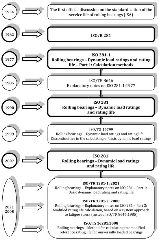
Figure 3.
ISO 281 standard development.
Considering the rapid advancement of rolling bearing technology at the time, particularly in the application of higher quality steels, the Swedish representative in the ISO proposed in 1964 to the ISO/TC 4/WG3 working group to revise the R281 standard. However, the working group did not accept this proposal initially. Three years later, the technical committee TC 4, prompted by the suggestion of the Japanese representative, changed the working group WG 3 and requested revision of the R281 standard [15,16]. As the American Rolling Bearing Manufacturers Association (AFBMA) revised American standards in this field, the American representative in the ISO submitted in 1970 a draft of the AFBMA standard on load rating and life of ball bearings for consideration (document ISO/TC 4/WG 3 (USA-1) 11), followed by a draft standard on load rating and rating life of rolling bearings in 1971 (document ISO/TC 4/WG 3 (USA-3) 19). Working Group TC 4/WG 3 evolved into Subcommittee TC 4/SC 8 in 1972. The AFBMA proposals underwent thorough deliberation at five meetings in the period from 1971 to 1974. The final proposal TC 4/SC 8 N23, with certain modifications, was initially circulated as an official draft of the international standard in 1976 before being adopted by the ISO Council in 1977 [15,16]. This marked the official release of a new version of the standard on methods for calculating load capacity and service life: ISO 281-1:1977 “Rolling bearings—Dynamic load ratings and rating life—Part 1: Calculation methods”. This version of the standard is almost the same as the previous version R 281, with very few changes. Primarily based on American research conducted during the 1960s, a new item was added to the standard that referred to the correction of service life for reliabilities other than 90% as well as for specific operating conditions and bearing materials. Clarifications on the derivation of the load-bearing and service-life formulas as well as additional information on adjustment factors were published as standard ISO 281-2 in 1979. TC 4/SC 8, and later TC 4, decided to amend and publish this document as a technical report with the designation ISO/TR 8646:1985 [15].
After 13 years, a new version of the standard was published. Standard ISO 281:1990 “Rolling bearings—Dynamic load ratings and rating life” [18] proposes methods for calculating the basic dynamic load rating of rolling bearings, made of modern, commonly used, hardened steel of good quality, with good manufacturing practice, based on conventional design and with a reliability of 90%. Also, this version of the ISO 281 standard proposes a modified expression for the calculation of bearing service life for reliabilities different from 90%, for certain specific characteristics of the material and bearing technology, as well as for specific operating conditions, including lubrication parameters. These influences are taken into account by life-adjustment factors a1, a2, and a3. For this version of the standard, as well as for the previous one from 1977, the theoretical basis and the derivation of expressions for the basic dynamic load rating, dynamic equivalent load, basic rating life, and adjustment factor of reliability (a1) are given in Technical Report ISO/TR 8646 from 1985 [15]. For the factors of material properties and technological procedures of bearing production (a2) and operating conditions (a3), the standard only provides descriptions and refers the user to the bearing manufacturer. Nine years after the publication of the latest version of the standard, the Technical Specification ISO/TS 16799:1999 “Rolling bearings—Dynamic load ratings and rating life—Discontinuities in the calculation of basic dynamic load ratings” [19] was published. This technical specification explains why the factors for calculating the basic dynamic radial and axial load rating differ depending on whether they are radial or axial angular contact bearings. Also, the specification provides instructions on how to recalculate the dynamic load rating of these bearings, for the aim of comparability of the results of the calculation of load rating and rating life, under the same geometric and operating conditions.
Manufacturers of rolling bearings, seeking to improve their products, were carrying out both theoretical and experimental research to identify and quantify the interdependence between material properties and bearing manufacturing technologies on one hand, and operating conditions, specifically lubrication and contamination, on the other. Consequently, they combined the two service life adjustment factors, a2 and a3 (as in the rating-life calculation method in the ISO 281 standard since 1990), into a single factor, denoted as a23. They provided recommendations and guidelines in their catalogs for determining this factor using the offered empirical diagrams. Experimental research conducted during the 70s and 80s of the last century revealed a significant correlation between the service life of the bearing and lubricant contamination. Also, bearing-life tests demonstrated that bearings under “clean” lubrication conditions exhibit longer service life than the values obtained by applying ISO calculation methods [20]. The difference arises from the differing material surface fatigue limit of bearing raceways. This influence is not considered in the standard calculation of dynamic load rating or rating life. Moreover, the standard fails to account for the interaction between fatigue load limit and lubrication as well as lubricant contamination. A new model for predicting the fatigue life of rolling bearings, developed by Ioannides and Harris [21], was based on the assumptions of the presence of these influences. In light of these advancements, the members of the technical committee TC4 incorporated these considerations into the evolution of life calculation methods, resulting in the publication of two amendments in 2000 [22,23]:
- ISO 281:1990/AMD 1:2000 “Rolling bearings—Dynamic load ratings and rating life—Amendment 1”
- ISO/281:1990/AMD 2:2000 “Rolling bearings—Dynamic load ratings and rating life—Amendment 2: Life modification factor aXYZ”.
Both of these Amendments were revised and withdrawn in 2007 with the publication of the subsequent version of the ISO 281 standard. Amendment 2 outlined a procedure to combine two factors, a2 and a3, into a single factor denoted as aXYZ. However, the standard did not provide a mathematical model for calculating this factor or offer guidelines for its determination, leaving it to the discretion of bearing manufacturers. Consequently, manufacturers such as SKF, FAG, NSK, and Timken each introduced “own factor” in their catalogs [24]. Simultaneously, some of these factors varied in terms of definitions, calculation expressions, and parameters for their determination, and are presented in tables and/or diagrams in the manufacturer’s catalogs. The DIN (Deutsches Institut für Normung) standard for the calculation of the rating life of rolling bearings was published in 2003, and subsequently, the fundamental concept of this standard, which pertains to the correction of expressions for rating life, was incorporated into the new ISO 281 standard published in 2007, along with the technical specification ISO 281/TS 16281 from 2008. In the revised version of the ISO 281 standard, the life modification factor aISO, was integrated. It includes four interconnected influences on bearing life: lubrication, contamination, load, and the fatigue limit of the raceway material. The evolution of the expression for the ball bearings is illustrated in Figure 4.

Figure 4.
Life formula through ISO standards (a1—probability factor; a2—production factor; a3—operational conditions factor; aXYZ—combined a1 and a2 factor; aISO—systems approach factor).
In the latest version of the standard ISO 281:2007 “Rolling bearings—Dynamic load ratings and rating life” [2], the calculation method is defined, with a reliability of 90%, by the basic rating life, made with quality technologies and of the most commonly applied high-quality steel, and for conventional operating conditions. At the same time, the standard also provides procedures for calculating the modified life for reliabilities different from 90%, specific lubrication conditions, and different levels of lubricant contamination as well as for different fatigue load limits. Theoretical foundations, additional derivations, and clarifications of standard expressions are given in two technical reports [16,25]:
- ISO/TR 1281-1:2021 “Explanatory notes on ISO 281—Part 1: Basic dynamic load rating and basic rating life”
- ISO/TR 1281-2:2008 “Explanatory notes on ISO 281—Part 2: Modified rating life calculation, based on a systems approach to fatigue stresses”.
The second edition of Technical Report ISO/TR 1281-1 [16] published in 2021 cancels and replaces the Technical Corrigendum [26] and the Standard first edition [27], which has been technically revised. With the publication of the first edition of Technical Report [27] in 2008, Technical Report TR 8646 [15] from 1985 was revised, withdrawn, and replaced. In Technical Report ISO/TR 1281-1 [16], a detailed derivation with explanatory terms is given for basic dynamic load rating, dynamic equivalent load, and basic rating life.
The Clause on the reliability factor in [27] was removed in 2009 by Corrigendum ISO/TR 1281-1:2008/COR 1 [26] because this life factor was discussed in much more detail in the second part of Technical Report ISO/TR 1281-2 [28]. In the second part of the technical report, the theoretical foundations and explanations for the calculation of rating life based on the systems approach are given as well. The report contains the following chapters:
- determining the reliability modification factor a1 and the modification factor of systems approach aISO
- presentation of the contamination level of lubricants from the ISO 4466 standard, applied in ISO 281
- impact of wear
- the influence of the corrosive environment on the service life of the bearing
- the fatigue load limit of the bearing
- influence of circular stress, temperature, and hardness of contamination particles on the service life of the bearing
- determination of lubricant viscosity parameters
The standardized method for calculating the rating life of rolling bearings does not account for the effects of rotated or misaligned bearing rings, nor does it consider the impact of internal radial clearance on service life. The technical specification ISO/TS 16281:2008 [29] outlines an enhanced service life calculation model that incorporates rotation, misalignment, operating clearance, and load distribution on the rolling elements, but for computer-based calculations. While the specification identifies and explains the need to address these influences on bearing rating life, it only provides basic starting expressions and partial derivations, lacking a comprehensive procedure for end-user application.
A working group of Technical Committee TC 4 and Subcommittee SC 8 is actively engaged in revising and amending ISO/DIS 16281 (Rolling bearings—Methods for calculating the modified reference rating life for universally loaded bearings), ISO/DIS 17956 (Rolling bearings—Method for calculating the effective static safety factor for universally loaded rolling bearings), and ISO/AWI TR 25165 (Rolling Bearings—Method for calculating the rating life with additional consideration of surface distress). This ongoing effort suggests further advancements in the development of standardized mathematical models for calculating the dynamic load capacity and rolling bearings’ service life.
6. Briefly about the Rolling Bearings Service Life
The service life of a rolling bearing refers to the number of revolutions that the rotating ring of the bearing completes relative to the stationary ring before the initial signs of fatigue in the material of the raceways or rolling elements. Each year, approximately 10 billion rolling bearings are manufactured worldwide [30]. However, only about 0.5% of bearings are replaced due to damage and failure (Figure 5). While half a percentage may appear negligible, it equates to 50 million instances of damaged or failed bearings worldwide in just one year. Because of that, there is a need to decrease the number of unexpected premature failures of rolling bearings. This can be accomplished in two ways: by objectively extending the service life of the bearing and/or by enhancing the accuracy and reliability of assessing and prediction the bearing service life.
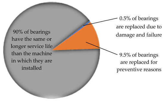
Figure 5.
Rolling bearings service life, data from.
An objective increase in the service life of bearings is achieved through various means, including enhancing bearing quality, ensuring proper installation, and maintaining correct operation. Improving bearing quality involves optimizing internal geometry (such as dimensions and shape of rolling elements, raceways, and cages), using superior or innovative materials (like high-purity steel, polymers, or ceramics), refining manufacturing and processing technologies, and optimizing bearing assembly processes. Proper installation of bearings in housings requires selecting suitable types and dimensions of bearings; ensuring proper fits of bearings in housings and on shafts; using appropriate tools, devices, and measurement instruments for installation; etc. Correct operation involves selecting suitable lubrication systems and lubricants for specific operating conditions, ensuring effective sealing, regularly refilling or changing lubricants, maintaining filtration systems, and implementing condition monitoring (such as temperature, vibration, and noise measurements) to detect early signs of bearing damage.
On the other hand, achieving the most accurate calculation of the bearing rating life indirectly contributes to increasing its service life. This implies that a bearing with a precisely calculated rating life should not fail before reaching that period, within specified reliability limits. A well-calculated rating life necessitates the presence of a robust mathematical model or life formula. Such a model should incorporate as many identified influencing parameters as possible on the service life of the bearing.
The development of the method for calculating the rolling bearing rating life started in the 1920s and is still ongoing. Initial research and significant contributions were made by figures such as Stribeck, Sjövall, Palmgren, and Lundberg, followed by Harris, Ioannides, Zaretsky, and others. During the following years, the procedure for calculating the rating life has been standardized. National standards from Germany, Sweden, and the USA hold particular significance in this regard, as the basis for the international ISO standard for rolling bearings. These national standards were established based on the extensive expertise of their national bearing manufacturers.
The international ISO standard for calculating the dynamic load rating and rating life of rolling bearings has undergone several revisions, incorporating improvements and integrating new knowledge into the mathematical model of service life. The most recent version was published in 2007, and ongoing efforts to enhance and update the standard continue to this day.
6.1. Causes of Rolling-Bearing Failures
In most cases, rolling-bearing failure results from material fatigue and insufficient lubrication (Figure 6). Inadequate lubrication means the use of inappropriate lubricants for the given operating conditions, insufficient or excessive lubricant quantities (both of which can equally reduce service life), and poorly estimated lubricant refill intervals. Bearing failure due to lubricant contamination (arising from ineffective sealing or filtration) occurs less frequently. Other factors contributing to bearing failure include installation errors (such as significant deviations from alignment or straightness), incorrect or inadequate alignment, mishandling, and bearing loads different from the predicted. Figure 6 presents the approximate average contribution of each cause of bearing failure to the overall failure rate. Deviations from these values may vary depending on the industry sector or specific application within a machine system. For instance, in the pulp and paper industry, the primary cause of rolling bearing failures is often contamination and inadequate lubrication and sealing, rather than material fatigue [30].
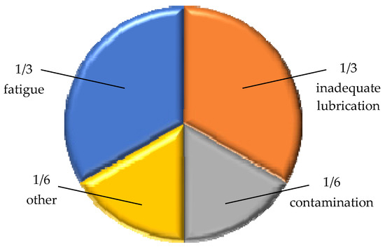
Figure 6.
Rolling bearing failure causes.
In the international standard ISO 15243:2017 [31], the failure modes of rolling bearings are categorized into six main groups and several subgroups. According to this standard, the primary forms of failure are rolling contact fatigue, wear, corrosion, electrical erosion, plastic deformation, cracking, and fracture.
Comparing the distribution in Figure 6 with the standard classification of bearing failure, it becomes evident that all failure modes, except fatigue, are due to inadequate lubrication, contamination, and other causes. It is a well-established thesis in rolling bearing theory that if the correct bearing is transported, stored, installed, and operated appropriately (with designated rotational frequencies and loads of specific direction and intensity), and maintained correctly (regularly lubricated with the appropriate lubricant type and quantity, and effectively sealed from contamination particles and moisture), then all causes of bearing damage are reduced except one: fatigue. According to conventional rolling bearing theory, bearings do not have indefinite dynamic durability, i.e., an unlimited operational life. Even under “ideal” design, operation, and maintenance conditions, fatigue will occur, influenced by load acting and rotation.
In the ISO standard on damage and failures of rolling bearings [31], fatigue is described as a change in the material structure caused by periodically changing stresses at the points of contact between rolling elements and raceways. Visually, fatigue failure is manifested by the separation of material particles from the contact surfaces. According to this standard, fatigue failure can be initiated on the surface or in the subsurface. In line with Hertz’s theory of contact deformations, at a certain depth below the contact surface, the shear stress reaches its maximum value. Under the influence of variable load in rolling contact, structural changes and the appearance of microscopic cracks occur at that depth, i.e., subsurface [31]. Like most high-strength materials, the steel used for manufacturing rolling bearing parts exhibits insufficient resistance to damage due to sensitivity to material imperfections created during steel production. The most common cause of subsurface microcrack formation in bearing parts, primarily along raceways, is material imperfections in the form of non-metallic origin inclusions [32]. During multiple cycles of periodic rolling contact, microcracks grow into cracks that propagate toward the surface. As a result, material particles detach from the surface in the form of flakes, leaving pits in their place. Further expansion and merging of these pits lead to more significant surface damage, such as increased flaking and peeling of the metal surface. In the theory of rolling bearings, this form of damage to contact surfaces (primarily raceways), caused by subsurface-initiated fatigue, is named spalling [33].
The calculation of the basic rating life of the bearing, according to ISO 281, is based on the assumption of subsurface-initiated fatigue. However, fatigue of the bearing contact surfaces can also be surface-initiated, resulting from surface damage to the material [31]. These damages often involve microscopic irregularities on the contact metal surfaces, occurring under reduced lubrication and kinematic sliding, accompanying relative rolling of the contact surfaces. In such cases, microcracks, microindentations, and microscopic gray-stained zones may occur. Additionally, plastic indentations on raceway surfaces, caused by hard debris particles or improper handling, can also lead to surface-initiated fatigue. The ISO 281 standard includes the influence of surface-initiated fatigue on the bearing service life by applying the modification factor aISO.
6.2. A Stochastic Approach to Service Life Estimation
By examining a group of bearings of the same type and dimensions, under identical operating conditions (load and rotation speed, type of lubricant and method of lubrication, and working environment), different service life values for each bearing would be obtained. The end of the service life is determined by the appearance of the first signs of fatigue on the contact surfaces of the bearing parts, primarily on the raceways. In 1924, Palmgren published a paper [4] on the service life of ball rolling bearings, marking the beginning of the development of the theory of rolling bearings service life. In 1939, Weibull presented his statistical theory of material strength in his paper [13], which could be a mathematical tool for predicting the dissipation of the service life of bearings observed during Palmgren’s experimental research. In papers [3,4], Lundberg and Palmgren published their life theory, based on Weibull’s stochastic approach. The basic expression for the service life of a rolling bearing is derived from this concept, which remains valid today.
6.3. Basic Rating Life
The standard ISO 281 defines the basic rating life as the service life corresponding to a reliability of 90% for rolling bearings made of the most commonly used high-quality steel, with good manufacturing quality, and operating under conventional operating conditions [2]. In Technical Report [16], an expression was derived that relates the load, dynamic load rating, and service life of balls and the raceway in contact:
where Q is the normal force in contact between the ball and the raceway and QC is the load-carrying capacity of the raceway in contact with the ball.
Since the ball load is proportional to the bearing load, then the loads QC and Q are proportional to the dynamic load rating (radial Cr or axial Ca) and the equivalent bearing load (radial Pr or axial Pa), respectively. Therefore, it can be written as follows [16]:
Based on the results of the tests conducted by Lundberg and Palmgren [3], the values of the Weibull parameter and other exponents in expressions (11) for ball bearings were determined: e = 10/9, c = 31/3 and h = 7/3, so that the exponent p = 3. The expression was derived for a reliability of 90%, i.e., the probability of failure is 10% (number 10 in the index of the mark L10). By substituting the exponent p, expressions (11) for the service life of radial and axial ball bearings can be written in the well-known form:
6.3.1. Dynamic Load Rating
Dynamic radial load is the constant static radial load that the bearing can theoretically withstand during the basic service life of 106 revolutions before the first signs of fatigue damage. In a single-row angular contact ball bearing, the radial load refers to the radial component of the load, resulting in a radial displacement of one ring relative to the other. A detailed description of the derivation of the expression for the dynamic load rating of rolling bearings is provided in Technical Report [16]. In the Standard itself [2], only final expressions are listed, along with instructions and tables for their application. The dynamic radial load rating of ball bearings can be determined based on the following expressions:
where bm is the load-carrying factor for the modern, most commonly used, high-quality bearing steel, under good manufacturing practice [2]; fc is the dynamic load factor, which depends on the material, geometry, and accuracy of bearing parts [2]; i is the number of rows of balls in the bearing; α is the contact angle of the balls with the raceways (α = 0° for bearings with radial contact, α > 0° for bearings with angular contact); Z is the number of balls in the bearing; and Dw is the ball diameter.
The dynamic axial load rating of an axial ball bearing is the constant axial load that the bearing can theoretically withstand during the basic service life of 106 revolutions before the first signs of fatigue appear. For an axial bearing with axial contact at an angle α = 90°, the dynamic axial load rating is determined similarly to the expression (13):
For axial ball bearings with angular contact, when α ≠ 90°, the dynamic axial load rating is given by the following expressions:
When a design engineer selects a rolling bearing and determines its rating life, it is necessary to calculate the dynamic load rating of the bearing because this information is provided in the bearing manufacturer’s catalog. The dynamic load rating, based on expressions (13)–(15), can be calculated by knowing all the parameters of the bearing internal geometry. However, even though these parameters are standardized, they are part of the technical documentation for bearing production, which is not publicly available.
Standard [2] provides this expression as information, including the description of its derivation in [16], to clarify the final expression for determining the rating life. Manufacturers of rolling bearings use expressions (13)–(15) when determining the values they will enter in their catalogs. However, a comparative analysis conducted in the case study presented in [17] reveals that the dynamic load ratings given in the catalogs of two representative manufacturers differ from each other and deviate from the values calculated using standard expressions (13)–(15). These differences could be caused by different values of the factor fc. Additionally, the real factor bm, determined experimentally by the bearing manufacturer, may differ from the standard recommended ones due to the constant development of the quality of applied materials and technologies in bearing production. Nevertheless, the deviations of the dynamic bearing capacities of different manufacturers from the values calculated using standard expressions are not greater than ±5%, depending on the manufacturer and series of bearings, as shown in the case study presented in [17]. Manufacturers have accurate data on bearing geometry and the materials of their parts, and they also conduct appropriate experimental testing of their products to ensure product quality and guarantee the declared characteristics. Therefore, the dynamic load capacities provided in the bearing catalogs of manufacturers are considered more authoritative than calculated values based on standard expressions.
6.3.2. Dynamic Equivalent Load
The dynamic equivalent radial load of a ball bearing with radial or angular contact, loaded with a combined radial and axial load, is determined based on the following expression [2]:
where Fr is the radial component of bearing load; Fa is an axial component of bearing load; X is the factor of radial load of radial ball bearings; and Y is the factor of axial load of radial ball bearing.
According to expression (16), two orthogonal support reactions (radial and axial) are reduced to one equivalent radial load, which has the same effect on the bearing load-carrying capacity and service life as the combined (universal) load. The factors for reducing the two components of the combined load to one equivalent load, denoted as X and Y, depend on a bearing internal geometry (such as the number and diameter of the balls, angle of contact of the balls with the raceways, and number of rows of balls in the bearing), the ratio of the axial and radial components loads, and, in some cases, the static load rating. The derivation of these factors is provided in Technical Report [16].
Axial ball bearings with a contact angle α = 90° can transmit only axial loads. The dynamic equivalent axial load for this type of bearing is Pa = Fa. The dynamic equivalent axial load of an axial ball bearing with angular contact (α ≠ 90°), loaded with a combined constant radial and axial load, is determined based on the following expression [2]:
where Xa is the factor of radial load of axial ball bearings and Ya is the factor of axial load of axial ball bearing.
According to (17), two orthogonal support reactions (radial and axial) are reduced to one equivalent axial load, which has the same effect on the bearing load-carrying capacity and service life as the combined (universal) load. The radial and axial load factors Xa and Ya are derived from the expression for the dynamic equivalent radial load Pr and are determined based on the radial and axial load factors of radial ball bearings [16].
6.4. Modified Rating Life
In the current version of the ISO 281 Standard [2], a systematic approach to more precisely determining rolling bearing service life is applied. Such an approach implies considering various influences on the service life of the bearing, through changes and interactions of mutually dependent influencing factors. In this version of the standard, in addition to the existing modification factor of reliability a1, the modification factor aISO was introduced, based on a systematic approach to calculating the rating life of the bearing. By modifying the basic rating life with these factors, an expression is obtained for the modified service life of the rolling bearing for reliabilities other than 90%, i.e., failure probabilities different from 10% (n ≠ 10):
The expression (18) for the modified rating life takes into account the lubricant characteristics, lubrication and sealing conditions, the degree of cleanliness of the working environment (lubricant contamination level), fatigue load limit, and the character and intensity of the bearing load. At the same time, mutual dependence among the mentioned factors of operating conditions was also considered.
6.4.1. Modification Factor a1
In the context of determining the service life of a group of identical rolling bearings working under the same operating conditions, reliability is defined as the percentage of bearings from that group that will reach or exceed the intended service life. The reliability factor was present in the version of the standard published in 1990. In version [2] from 2007, this factor was changed and new ones were added. Technical Report [25] from 2008 describes and explains the modification factor a1 in more detail.
6.4.2. Modification Factor aISO
In rolling bearings made of the most commonly used high-quality steel and by using high-quality technological procedures, the dynamic durability of the contact surfaces of rolling elements and raceways is achieved at contact stresses approximately equal to 1500 MPa. Additional stresses are also included caused by operating conditions, as well as by tolerances and the fits of bearing on the shaft or in housing. A decrease in manufacturing accuracy and/or material quality can lead to a reduction in the surface dynamic durability of bearing parts. Practical experience has shown that in many cases involving various types and sizes of bearings, the actual contact stresses exceed 1500 MPa. Furthermore, unfavorable operating conditions can increase these stresses, thereby shortening the service life of the bearing. Operating conditions can impact stresses and material surface strength in the following ways: surface damage, such as scratches and indentations, can lead to stress concentration; a too-thin oil film results in increased shear stress in the contact between the rolling elements and the raceways; increased temperatures reduce the surface dynamic strength of the bearing parts; and excessive interference in the fit between the inner ring of the bearing and the shaft sleeve causes an increase in circular stresses.
The various influences on the service life of the bearing are interconnected and interdependent. Hence, a systematic approach to calculating the bearing service life is essential. This was achieved by developing practical methods to determine the appropriate modification factor of the aISO systems approach, which considers the fatigue load limit and facilitates quantification of the impact of lubrication and environmental contamination on the bearing service life.
The modification factor for the systems approach to calculating the service life is determined based on theoretical analytical research; experimental laboratory tests; and practical experience in bearing design, production, and operation. Apart from the bearing type, fatigue load limit, and operating load, this factor also considers bearing type and size, rotational speed, lubrication conditions (lubricant type, viscosity, additives), working environment (sealing, contamination level), and contamination particles (particle size relative to bearing size, lubrication, and lubricant filtration methods) as well as environmental cleanliness during bearing assembly.
In Standard [2], 12 expressions are provided for determining the aISO factor, depending on the type of bearing (radial ball and roller bearings, axial ball and roller bearings) and the lubricant viscosity ratio. By introducing appropriate constants instead of their numerical values, these 12 expressions can be reduced to two expressions, one for radial bearings and the other for axial bearings.
The expression for the aISO factor, according to [17], is as follows:
where κ is the viscosity ratio; eC is the contamination factor; Cu is the fatigue load limit; P is the dynamic equivalent load; and A and B are constants.
The constants A and B depend on the type of bearing and viscosity ratio. They were introduced in standard aISO expressions first in [17], and their values were determined based on standard expressions [2]. An overview of these constants for radial and axial ball bearings is given in Table 1.

Table 1.
Constants A and B for ball bearings in expressions (19).
In Standard [2], diagrams of function aISO = f(eCCu/P) determined by expressions (19) and (20) are provided. Each diagram shows a family of curves for viscosity ratios κ = {0.1; 0.15; 0.2; 0.3; 0.4; 0.5; 0.6; 0.8; 1; 2 and 4}. For intermediate values not listed, it might be challenging to read exact values, but in such cases, the given expressions can be used. Conclusions about the limit values of influencing variables will be made based on these diagrams. The modification factor is limited to aISO = 50, and the set of influencing factors is limited to eCCu/P = 5. If the selected lubricant and operating conditions (temperature) result in κ > 4, then, in the calculations, it is assumed that κ = 4. Viscosity ratios κ < 0.1 are not covered in the provided expressions and diagrams, making the calculation of the modification factor aISO impossible [2].
The viscosity ratio of the lubricant indicates the quality of the oil film formed between the balls and the raceways. Adequate lubricant should provide the required minimum viscosity at the normal operating temperature to form a suitable oil film between the contact surfaces. Therefore, the effectiveness of the applied lubricant depends on the degree of separation of the contact surfaces at operating temperatures, conveniently assessed through the following viscosity ratio:
where ν is the actual kinematic viscosity at the operating temperature; and ν1 is the reference kinematic viscosity, required to obtain adequate lubrication conditions.
The actual kinematic viscosity at the operating temperature of the bearing depends on the type of lubricant and its specified viscosity at a certain temperature. This information is typically provided by all rolling bearing manufacturers in their catalogs. The reference kinematic viscosity represents the required viscosity of the lubricant applied to lubricate a bearing of specific dimensions operating at a certain rotational speed. It is determined based on the following expression [2]:
In Standard [2], there is a corresponding nomogram for the graphical determination of the reference kinematic viscosity, formed based on expression (21). The viscosity ratio of the lubricant κ is determined by expression (20) for lubrication with mineral oils and for bearings manufactured using high-quality technological processes. Equation (21), or corresponding standard diagrams, can be indirectly used for some synthetic oils under special conditions described in the Standard. Because of their advantages over other types of lubricants, greases are used for lubrication in more than 80% of rolling bearing applications of all types. The same expressions and diagrams can be applied in the case of determining the viscosity ratio of grease-lubricated bearings, where the considered viscosities refer to the base oil. Base oils can be mineral or synthetic, with different viscosities and other rheological properties.
The eC factor considers the influence of lubricant contamination in the oil film between the rolling elements and the raceways in calculating the service life of the rolling bearing. In the actual operating conditions of rolling bearings, the lubricant contains a certain amount of hard particles of contamination. The shape, size, concentration, and material of these particles in the lubricant depend on several factors: the quality of the technological procedures of manufacturing and assembly of the bearing, the quality of the working environment, the method of lubrication, and the adequacy and efficiency of the sealing system and lubricant filtering methods. Contamination particles in the lubricant can originate from various sources: functional (arising from the bearing operating environment), technological (not removed after the manufacturing and processing procedures of the bearing parts), and those generated during bearing operation due to contact surface wear. Rolling bearings typically operate in an elastohydrodynamic lubrication mode, where the oil film between the rolling elements and the raceways is usually about 1 μm thick [12]. Contamination particles smaller than the thickness of the oil film pass through the elastohydrodynamic contact with the lubricant without causing damage to the contact surfaces. However, many contamination particles found in the lubricant are larger than the oil film thickness and can interact with the contact surfaces in various ways. According to Standard [2], expressions are provided for determining the contamination factor for different lubrication methods, including oil circulation online and offline filtering systems; oil bath lubrication; and grease lubrication.
For oil mist lubrication, the Standard refers to Technical Report [25]. In the Standard, there are 15 expressions and 14 corresponding diagrams for determining the contamination factor for all the aforementioned lubrication methods. These expressions share a similar form, but the constants differ depending on the lubrication method and the level of contamination. A general formula for determining the contamination factor, derived from standard formulas, is presented in paper [17]:
where E and F are constants that depend on the lubrication method and the level of lubricant contamination as shown in Table 2.
Table 2.
Constants E and F for ball bearings in expressions (22).
In the case of rolling bearings lubricated with grease, the determination of the contamination factor relies on qualitative descriptions of grease contamination formulations provided in standard tables [2]. The standard outlines five levels of contamination or lubricant cleanliness: high cleanliness, normal cleanliness, slight to typical contamination (where the contamination factor also depends on the bearing size), severe contamination, and very severe contamination. Through expressions and diagrams provided, users can precisely determine the contamination factor for specific operating conditions, such as lubrication method and contamination level. These diagrams are also applicable to mixtures of particles with different hardness and strength, though only hard particles (hardness greater than that of the contact surfaces) and larger than the oil film thickness are considered to affect bearing service life. The Standard additionally includes a table offering approximate recommendations for the contamination factor based on qualitatively described lubrication and filtering conditions. It is assumed in this table that bearings are properly lubricated. The Standard does not cover the influence of water and other liquids as potential lubricant contaminants [2].
Additives play a significant role in enhancing the lubricating properties of oils and greases, improving their operational characteristics. Standard [2] addresses special EP (extreme pressure) additives, which mitigate surface wear under high-pressure conditions. If the viscosity ratio is κ < 1, the contamination factor eC is ≥0.2, and the lubricant contains proven effective EP additives. A viscosity ratio value κ = 1 can be employed to determine the contamination factor eC and the modification factor aISO. This increase in viscosity ratio is attributed to the expected beneficial effect of EP additives, enhancing the smoothness of contact surfaces. Consequently, the modification factor is aISO ≤ 3. In instances of severe contamination, where the contamination factor eC < 0.2, the efficacy of the EP additive is contingent upon the level of actual contamination and can be assessed through testing of the real bearing assembly or by subjecting the bearing itself to testing on an appropriate test rig [34].
To ensure the accurate application of all the standard recommendations for the most precise assessment of the service life, it is imperative that the bearing operates under the expected operating conditions right from the initial startup of the machinery as well as after the refill of the lubricant. These are all the starting assumptions of the Standard, and any deviation from the anticipated operating conditions could result in inaccuracies in the calculation of the rating life according to the proposed standard procedure, thus compromising the reliability of the estimated service life.
The modification factor aISO is outlined in Standard [2] as a function of the ratio of surface fatigue stress limit to contact stress (σu/σ). The contact stress σ on the raceway depends on the load distribution between rolling elements as well as on the distribution of subsurface stresses at the most heavily loaded contact point between the balls and raceways. The fatigue load limit Cu is introduced into the calculation of the modification factor aISO. In the definition of static load rating C0 in ISO 76 [35], Cu represents the rolling bearing load (P = Cu) where the contact stress σ at the most heavily loaded contact point equals the surface fatigue stress limit σu. According to [2], the ratio σu/σ can be approximated by the ratio Cu/P, allowing the modification factor aISO to be expressed as a function of this ratio. The fatigue load limit Cu is not the sole criterion for bearing selection, but it is one of the influential parameters in the system’s approach for calculating rating life. A rolling bearing with an operating load less than the load corresponding to the dynamic strength of the contact surfaces doesn’t necessarily imply indefinite operation. Local boundary or mixed friction at the contact between rolling elements and raceways can result in localized stress elevation in the raceway material. Consequently, even if the bearing loads are below the limit fatigue load, the fatigue stress limit may be locally exceeded [2]. These influences are included in the standard procedure for calculating bearing rating life through advanced analytical methods for determining the fatigue load limit. An outline of the theoretical fundamentals for determining the fatigue load limit is provided in one of the annexes of Standard [2]. It is defined as the load at the individual contact of the rolling elements with one of the raceways, reaching the surface fatigue stress limit.
For complete radial ball bearings, the fatigue load limit is determined as follows [2]:
For complete axial ball bearings
The quantity Qu in expressions (23) and (24) is the minimum limit fatigue load in the most heavily loaded contact (at the place of the most heavily loaded ball, depending on the load distribution in the bearing):
where Qui is the fatigue load limit in the most heavily loaded contact on the inner raceway and Que is the fatigue load limit in the most heavily loaded contact on the outer raceway.
The fatigue load limit Cu depends on the bearing type and size, bearing internal geometry, the quality of the bearing manufacturing, and the surface dynamic strength of the bearing parts material. All the listed data are available to the rolling bearing manufacturers. That is why they determine the fatigue load limit and provide it in catalogs for each type, size, and series of rolling bearings. The standard, however, also provides a simplified method for determining the fatigue load limit, according to which fatigue load limit can be determined using approximate expressions as a function of the static load rating C0 [2]:
In Standard [2], it is noted that the values calculated by applying expression (26) may differ significantly from the results obtained by the precise method. From a theoretical point of view, expressions (26) are interesting because they depict the essence of the fatigue load limit. It is defined based on an analogy with the static load rating. According to the standard definition, the static load rating C0 is the bearing load (radial or axial, depending on the bearing type) where the static contact stress at the point of the most heavily loaded contact between the balls and the raceways is 4200 MPa [35]. The fatigue load limit Cu is the bearing load (radial or axial, depending on the bearing type) during which the surface dynamic strength is reached at the point of the most heavily loaded contact between balls and raceways, i.e., the ultimate contact stress of 1500 MPa [2]. According to expression (26), this means that the bearing load corresponding to the dynamic strength of the most heavily loaded contact is approximately 22 times less than the load corresponding to the static load rating.
After a detailed consideration of expression (19), the following can be concluded:
- The factor aISO depends on the bearing properties and operating conditions.
- The factor aISO is a function of three quantities: the viscosity ratio of the lubricant κ, the contamination factor eC, and the Cu/P ratio of the fatigue load limit and the bearing equivalent operating load.
- The viscosity ratio of the lubricant κ depends on the operating conditions (the degree of viscosity of the applied oil at a temperature of 40 °C, bearing operating temperature, and the bearing rotation speed) and on the bearing size (the pitch diameter, which is a function of the bore diameter and bearing outer diameter).
- The contamination factor eC depends on the operating conditions: lubrication method (with circulating oil, oil bath, or grease) and sealing, the efficiency of filtering (if implemented), contamination level of the working environment with hard particles, and the bearing size but also the viscosity ratio of the lubricant κ.
- The Cu/P ratio of the fatigue load limit and bearing operating load depends on the bearing properties (type—internal geometry, size, series, and material) and the intensity and character of the bearing load (radial, axial, combined).
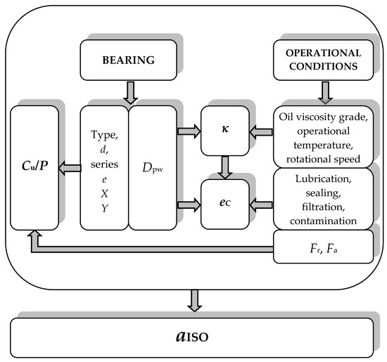
Figure 7.
Modification factor of the systems approach to the rating life calculation.
Considering all identified and quantified influences on rolling bearing service life, along with their complex interdependence, the introduction of a modification factor through the systems approach into the standard procedure for rating life calculation is fully justified. The introduction of this modification factor represents a crucial advancement in the evolution of expressions for calculating the rolling bearing service life. This modification factor, as depicted in standard diagrams provided by manufacturers, can both exceed and fall below 1. This implies that depending on the combination of bearing characteristics and operating conditions, the actual service life can either exceed or fall short of the basic rating life.
The aISO factor, as indicated by standard diagrams, can reach values up to 50 [2]. This suggests that the modified service life can be many times longer under actual conditions compared to the basic rating life. This extended service life depends on well-designed bearings chosen for specific applications and highly favorable operating conditions, including lubrication, sealing, lubricant filtration, and environmental cleanliness. This phenomenon, where the real service life of the bearing significantly deviates from the basic rating life, has been observed by bearing users in practical machine system applications or experimentally validated in bearing manufacturers’ research centers. Hence, the definition and incorporation of the aISO factor into calculations have made a significant contribution to more accurately assessing the rolling bearing service life.
6.4.3. Other Influences
Currently, the standardized expression (1) for determining the rolling bearing service life incorporates reliability, bearing construction characteristics, and operating condition characteristics (Figure 7). By considering these factors, the expression for the basic rating life has been modified, thereby increasing the accuracy of estimating the rolling bearing service life. However, industrial practice and scientific research have identified several other factors that influence bearing service life, which have not been taken into account yet. These factors include wear, corrosive environments, circular stresses, temperature, hardness of foreign particles, load distribution among rolling elements, internal clearance, misalignment of rings, etc. While these influences are recognized as significant by the ISO subcommittee responsible for bearing load ratings and rating life estimation, they are not extensively discussed in the Standard itself [2]. Brief presentations of these factors can be found in Technical Report [25] and Technical Specification [29], both published after the last revision of ISO 281. These documents offer information and qualitative guidance on additional factors affecting the dynamic load rating and rating life calculation, serving as the current clarifications and instructions available to users of the Standard. Furthermore, the latest version of the ISO 281 standard does not incorporate the effects of ring misalignment and internal clearance on rating life calculation. The Technical Specification [29], currently under development, hints at the next step in further refining the standardized expression for calculating the rolling bearings rating life.
7. Research of Bearing Life through the Century
The beginning of the development of rolling bearing technology, as well as their industrial production, is considered to be the invention of the pedal bicycle in 1868 [37]. Hertz developed his theory of the contact of elastic bodies in 1881, and Stribeck presented his model of load distribution in a ball bearing in 1901. The basic concept of the service life of rolling bearings was developed by Palmgren and published in 1924. Then, together with Lundberg, he supplemented his theory with a stochastic approach to calculating service life and published it in 1947 and 1952. In the following years, it was shown that their mathematical model of service life corresponds to most of the results of service life tests, which were then carried out by bearing manufacturers. The leading manufacturers of that time, from Sweden, the USA, and Germany, joined together in the same effort to form a unique standardized formula for calculating the service life of rolling bearings, which would be to the general benefit of both manufacturers and users of rolling bearings. The bearing manufacturers had the results of testing the service life of their products. Those results were collected by the American Standards Association, requesting from the National Bureau of Standards, i.e., belonging to the Committee for Ball and Roller Bearings, to process them and then compile an appropriate report. The results of detailed statistical processing of the obtained data on the testing of the service life of rolling bearings were published in 1956 [38]. According to this report, 213 series of tests were performed and 4948 ball rolling bearings were analyzed. At the same time, independent research was carried out by Tibor Talian (SKF Philadelphia, USA) and his results were published in 1976 [39,40]. He examined 2500 bearings under different operating conditions and determined that bearing failure does not occur only as a result of subsurface fatigue, which is Palmgren’s basic assumption, but that the service life of the bearing is also affected by surface-induced fatigue. Nevertheless, the original Lundberg–Palmgren mathematical model of the bearing service life, based on the subsurface fatigue of the raceways, remained the “nucleus” of all further research—the existing basic theory, which was extended and supplemented [41]. The Lundberg–Palmgren method of calculating the service life of rolling bearings prevailed over all other methods and was accepted by the international standardization organization ISO. The proposed method was previously checked and confirmed by the American Bureau of Standards [41].
Although the service life calculation method is standardized, development and research in the field of rolling bearing theory have not stopped. Companies that produce rolling bearings continue to lead advanced research on the impact of bearing load-carrying capacity and service life. In addition to their main activity, production, they have also developed large, well-equipped, and organized research centers. In addition to manufacturers of rolling bearings, research was also carried out by specialized research institutes for the needs of specific and purpose-built structures and technologies (aeronautical, military, etc.) as well as many other research and academic institutions around the world, within their scientific and research projects. All this is happening with the intensive development of mechanical engineering and technology, information technologies, measuring equipment and instruments, and accompanying dedicated software, which enabled a higher quality of experimental and numerical tests, both from the aspect of organization and technique of conducting research as well as from the aspect of accuracy and reliability of obtained results and their processing and analysis.
The theory of the service life of rolling bearings has been around for a century and has changed, from the laying of the foundations to the present day. The most important authors, based on whose research the ISO 281 standard for the calculation of dynamic load capacity and service life of rolling bearings was significantly changed in 2007, are Tedrik Harris and Statis Ioannides. Ervin Zaretsky is the biggest critic of the accepted and standardized model of the service life of rolling bearings.
7.1. Basic Life Theories
In 1924, Arvid Palmgren published his analysis of the rolling bearings service life. According to Palmgren, the service life is limited by the fatigue of the surfaces in rolling contact. Assuming that the material of the bearing parts has a certain dynamic strength, i.e., stress at which it can withstand an infinite number of load cycles without fatigue occurring, the bearing life curve should be asymptotic. This exponential function was first proposed and described by Palmgren in his paper [4]. Valody Weibull published his theory of probability distribution of damage in 1939 (Table 3—Weibull) [13,42].
Table 3.
A comparative review of expressions for the reliability and basic service life.
In 1945, Palmgren derived an expression for determining the service life of a rolling bearing based on the Weibull distribution of the probability of damage. Then, in cooperation with Lundberg, he modified and published it in 1947 and 1952 [3,4]. Zaretsky, in a paper [43], states that similar considerations, in connection with the determination of stress below the Hertz contact surface, were published in 1930 [44]. However, as Zaretsky critically states in [43], Lundberg and Palmgren do not list this work among the references. For the values of the calculated service life to correspond to the experimentally obtained values, Lundberg and Palmgren introduced the distance zo, the depth below the Hertzian contact surface at which the critical shear stress τo has the highest value, into the Weibull expression for reliability and service life (Table 3—Weibull).
In the first decades of the last century, engineering practice dictated a deterministic approach to designing and calculating machine elements [43]. Palmgren was the first person to advocate a stochastic approach to engineering design. With that attitude, Palmgren was decades ahead of his time. His concept has been accepted by the scientific and professional public and represents the basis of the methodology of the ISO standard for the calculation of the rolling bearing dynamic load rating and rating life. In 1985, Ioannides and Harris published their theory of rolling bearing service life, which was supplemented by the Lundberg–Palmgren theory. They did not criticize the Lundberg–Palmgren theory in their publications. They justified the perceived shortcomings with the explanation that at the time of the creation of the Lundberg–Palmgren theory, in the 1940s and 1950s, the proposed and established recommendations for calculating the rolling bearings service life were sufficiently representative, fully appropriate, and followed the current production technologies and machine materials as well as the procedures for condition monitoring, maintenance, and testing of machine systems [21].
The addition of Ioannides and Harris to the Lundberg–Palmgren theory of service life of friction bearings is based on the introduction of the fatigue limit. It was explained and proven by the results of experimental research and numerical analysis, i.e., using the finite element method for determining the real values of Hertz stresses [45]. Instead of the critical shear stress τo in the Lundberg–Palmgren equations for reliability and service life (Table 3—Lundberg–Palmgren), Ioannides and Harris introduced the difference (τo − τu), where τu is the fatigue limit, i.e., the highest shear stress under which contact surface fatigue will not occur at an infinite number of cycles of load changes (Table 3—Ioannides–Harris). In their model of reliability and service life of rolling bearings, they use exponents e, c, and h, which are the same as in the Lundberg–Palmgren model. At the same time, the authors in [21] note that a large number of tests should be performed to confirm or correct these exponents according to modern materials, design, and bearing technology, as well as modern measuring systems. When the fatigue limit τu = 0, then the exponent of Hertz stress, with the same parameters e, c, and h, is the same as in Lundberg and Palmgren, i.e., n = 9. The Ioannides–Harris model, for the special case without fatigue limit τu, reduces to the Lundberg–Palmgren model.
The concept of the fatigue limit was first proposed by Palmgren in 1924 [1], but he soon rejected it and did not mention it in his later papers. Sixty years later, Ioannides and Harris, in their theory of rolling bearing service life, applied Palmgren’s concept of the fatigue limit. They state that the fatigue limit was introduced to exclude correction factors from the life formula, which takes into account the material properties of the bearing parts, as well as the technology of their production and processing [21]. In their model, Ioannides and Harris considered the elementary volume exposed to a variable load and then integrated it (Table 3—Ioannides–Harris). Also, in their expression for service life, the Hertz stress exponent is a function of the fatigue limit, for values of the fatigue limit τu > 0, i.e., n(τu). In this model, the stress τu is the von Mises critical stress [43].
The latest ISO procedure for determining the rating life of rolling bearings [2] is based on [46] and the concept of the fatigue limit τu. However, although the initial considerations are based on supplementing the Lundberg–Palmgren expressions for reliability and service life with the fatigue limit (Table 3), the expression for the basic rating life has not been changed in the ISO procedure. The fatigue limit is indirectly contained in the modification factor aISO, through the values of the fatigue load limit Cu. It is a property of each bearing, which is defined as the load on the bearing, at which the von Mises stress τu = 900 MPa will be reached at the most heavily loaded point of contact between rolling elements and the raceways, i.e., Hertz contact stress σHmax = 1500 MPa. The values of Cu are given in the rolling bearing catalog tables. In paper [43], Zaretsky states that there are two issues related to the application of the fatigue limit in determining the service life of the bearing according to the Ioannides–Harris model. First, in his opinion, the stress τu is a compressive residual stress and does not reflect the presence of a fatigue limit. Another problem is that there was no data in the literature available at the time, that would harmonize τu and the dynamic strength of bearing parts made of special-purpose steels, such as AISI 52100. Zaretsky states that in some publications it was experimentally shown that for high-quality steels, such as AISI 52100, the fatigue limit cannot be reached even at very low stresses.
Lundberg and Palmgren supplemented the Weibull function of reliability and service life; Ioannides and Harris supplemented the Lundberg–Palmgren function; and Zaretsky, in his service life model (Table 3—Zaretsky), returned to the Weibull equation (Table 3—Weibull) and transformed it. Zaretsky’s author team first published a detailed account of their service life model in an internal NASA document [47], and then in 1996 in the Journal of the American Society of Tribology and Lubrication Engineers (STLE). Zaretsky devoted a large number of publications [37,43,45,47] to the critical analysis of the Lundberg–Palmgren and Ioannides–Harris model of the rolling bearings service life, precisely because, since 1962, these calculation procedures have been standardized and accepted by bearing manufacturers and users. Zaretsky and his collaborators proposed a generalized mathematical model of rolling bearing reliability and service life, based on the Weibull function for structural life prediction and discrete stressed volume, as conducted by Ioannides and Harris, with certain differences in approach.
The Lundberg–Palmgren theory of rolling bearing service life is a modified Weibull theory. The original scientific contribution of Lundberg and Palmgren was to understand the possibilities and accept the application of Weibull’s theory to rolling bearings as well as to adapt the geometry and material characteristics of bearing parts to Weibull’s parameters. However, Weibull’s theory, based on the assumption that every crack always leads to damage, is not completely valid for rolling bearings [43]. Zaretsky cites frequent examples from industrial practice and results of experimental research when cracks do not reach the surface to form a spall (a flake of separated material from the contact surface, due to subsurface fatigue [21]). Lundberg and Palmgren, and later Ioannides and Harris, ignored the fact that in the case of multi-cycle fatigue cracks, the crack initiation alone lasts more than 95% of the service life and that the crack propagation, which follows, lasts a negligible time, about 5% of the total service life of the bearing. That’s why Zaretsky excluded the influence of distance zo on service life from his model. Zaretsky justified this, in his opinion, wrong setting of the Lundberg–Palmgren theory by saying that at the time of Palmgren’s theory of the rolling bearings service life, the phenomena of high-cycle and low-cycle fatigue were only at the beginning of formulation and research.
In [48], Zaretsky transformed the Weibull equation of service life so that the service life does not depend on the ratio of the exponents c and e (Table 3—Zaretsky). The material constant A in the expressions for the service life of all authors (Table 3) allows the solutions of the derived equations to be adapted to the experimentally obtained data, exactly as Palmgren did in his first papers. In [47], the first quantitative comparison of different theories and approaches to the estimation of service life was made.
An interesting fact is that with Zaretsky, the exponent in the life formula of ball bearings is p = n/3 = 12/3 = 4, and in other models, including the standard expression for rating life p = n/3 = 9/3 = 3. Zaretsky explains this in papers [14,43,47], asserting that in recent times, higher quality steels (in terms of composition and production technology) are used for the production of rolling bearings than at the time of Lundberg and Palmgren. In [43], Zaretsky provides a comprehensive overview of the results of his research and studies by other authors, proving that in the case of ball bearings, the exponent p is greater than 3. In Palmgren’s time, the exponent p = 3 corresponded to reality, considering the technology of obtaining steel at the time, which is why it was generally accepted by manufacturers and users of bearings. Practice often shows that the actual service life of ball bearings can be up to 20 times greater than the one calculated by applying the standardized Lundberg–Palmgren expression with the exponent p = 3. Therefore, Zaretsky states that indicating a different exponent in the life formula is no more than mere academic interest and proving the greater accuracy of his mathematical model. The introduction of that change should be seriously considered in the future development of the ISO 281 standard because designers of machine systems require a reliable mathematical tool for the most accurate and reliable prediction of the service life and performance of rolling bearings [47].
Zaretsky paid great attention to the accuracy of the expression for determining the service life of the bearing. The expressions of Lundberg–Palmgren and Ioannides–Harris are based on the assumption that the service life of the bearing depends on the service life of the rings, but not on the service life of the rolling elements (their possible failure is neglected). According to Zaretsky, the failure that limits the service life of the bearing is contact fatigue of the surfaces, both the raceway of one or both rings, as well as the rolling elements. The damage of rolling elements due to fatigue is variable but statistically predictable, depending on the type of material (composition and cleanliness of steel), the technological procedure of obtaining steel, manufacturing, and thermal treatment of rolling elements, as well as operating conditions.
Zaretsky derived an expression for the service life that depends on the probability of failure of the set of balls in the bearing, in addition to the probability of failure of the rings due to surface fatigue of the raceways [43]. In [14], Zaretsky provides individual expressions for calculating the share of the service life of individual bearing components (outer ring, inner ring, and set of balls) in the service life of the complete bearing. He verified his expressions for the distribution of failure on parts of the bearing based on a comparison with the results of a virtual experimental test of 31,400 pieces of bearings (ball, radial, and angular contact, bore diameter 50 mm), using the Monte Carlo method. At the same time, the results of his analytical model and the conducted simulation showed a high degree of correlation. According to the results presented in [14], in radial ball bearings, the probability of failure of the inner raceways is 70%, and the probability of failure of the outer raceways and rolling elements is approximately equal and amounts to 15% each. In the case of angular contact ball bearings, due to the engagement of all bearing balls in the transmitted loads, the failure probabilities of the inner ring raceway and the balls are approximately equal and amount to 45%, and the failure probability of the outer ring raceway is about 10%. Additionally, Zaretsky also dealt with the influence of the balls and raceway dimensions ratio on the service life of individual rings. Based on the conducted research, in [14], he introduces and analyzes the appropriate service life correction factor, depending on the parameters of the bearing internal geometry.
7.2. Other Main Contributions
Based on the material presented, it can be concluded that the mathematical modeling of the service life of rolling bearings is extremely complex, but also fundamentally and essentially important for designers, manufacturers, users, and maintenance engineers. Therefore, the current standardized expression for calculating the service life of rolling bearings created a hundred years ago and partially supplemented and extended over time, requires further development.
In addition to the described dominant results of influential research centers and individuals, which changed the approach to standardized service life assessment during all these years, many authors have made their small contributions to the further elucidation of the phenomena laid down in the foundations of the theory of service life assessment of rolling bearings [49,50,51,52,53,54,55,56,57,58,59,60,61,62,63,64,65,66,67,68,69,70,71,72,73,74,75,76,77,78,79,80,81,82,83,84,85].
Remaining useful life (RUL) is a term often present and discussed in present-day publications about the service life of rolling bearings. It is not just a physical quantity and some numerical value. It is a complex concept of critical condition control in the fields of engineering and maintenance in industries that apply machinery and equipment based on rotary motion. Understanding and predicting the RUL of rolling bearings is essential to optimizing maintenance procedures, reducing downtime, and ensuring equipment reliability and safety. RUL is defined as the estimated time during which a rolling bearing will continue to operate under specified operating conditions before reaching a predicted service life. Thanks to the accurate assessment of RUL, reliable machine operation is ensured by replacing the bearing before failure. In this way, by precisely determining the moment when the bearing will fail, unnecessary maintenance and operation stoppages are reduced to a minimum, i.e., costs are reduced. In addition to the economic importance, the prevention of catastrophic failures that can lead to major machinery breakdowns and operator injuries is very important and should be emphasized. RUL depends on the load and rotational speed, exposure to contamination particles, water, moisture, and temperature changes, and lubrication as well as proper installation. Traditional techniques that can be used to predict RUL are vibration analysis, acoustic emission, thermography, and lubricant analysis. Machine learning and artificial intelligence (AI) are new modern techniques, based on the application of data from sensors and time records introduced into appropriate algorithms and models for RUL prediction.
Based on the analysis of the available literature and published research results, it can be stated that there is a great increase in interest in the determination of RUL [86,87,88,89,90,91,92,93,94,95,96,97,98]. The recent surge in interest in RUL rolling bearings is driven by advances in sensor technology, data analytics, neural networks, machine learning, and artificial intelligence. These technologies enable more accurate and efficient monitoring of the bearing condition in real time. Key trends are the Internet of Things—IoT (integration of smart sensors and IoT devices for continuous monitoring and data collection), big data analytics (analyzes large amounts of operational data to identify patterns and predict errors), digital twins (creation of digital replicas of physical assets for simulation and predicting their behavior and RUL), and AI and machine learning (developing predictive models that learn from collected data to improve the accuracy of RUL predictions) [86,87,88,89,90,91,92,93,94,95,96,97,98].
8. Conclusions
This review paper provides an overview of the current state of the development and international standardization of the mathematical model and methodology for estimating the rolling bearings service life.
The research centers of the world’s major manufacturers of rolling bearings are at the forefront of research on this topic. They possess well-equipped laboratories with the most modern bearing testing devices, measuring equipment, and software support for processing results. Additionally, they have almost unlimited quantities of samples for testing from their production program. Furthermore, they employ top researchers and the latest equipment for numerical research, modeling, simulations, and optimization. They also receive feedback on the operation of the bearings from their distributors, machine system constructions in which the bearings are installed, and end users of those systems.
Predicting the remaining useful life (RUL) of rolling bearings is a vital aspect of modern engineering and maintenance practice. It involves a multidisciplinary approach, combining mechanical engineering principles with advanced data analytics and sensor technologies. As industries continue to adopt more sophisticated predictive maintenance strategies, the importance of accurately determining RUL will only grow, leading to safer, more efficient, and cost-effective operations.
Scientific publications of all levels and categories, as well as scientific and professional conferences around the world, often present papers on various aspects of the development of the mathematical model of the rolling bearings service life. Each of these works represents a small but significant contribution and a step towards the development of the most realistic and reliable model for predicting the rolling bearing service life.
Author Contributions
Conceptualization, T.L., A.M. and I.A.; methodology, T.L., A.M. and I.A.; validation, T.L., A.M. and B.S.; investigation, T.L., I.A. and M.S.; writing—original draft preparation, T.L.; writing—review and editing, T.L., A.M. and I.A.; visualization, B.S. and M.S.; supervision T.L., A.M. and B.S. All authors have read and agreed to the published version of the manuscript.
Funding
This research received no external funding.
Data Availability Statement
No new data were created during the study.
Acknowledgments
This work was supported by the Ministry of Science, Technological Development and Innovations of the Republic of Serbia (Contract No. 451-03-65/2024-03/200105, dated 5.2.2024 and No. 451-03-66/2024-03/200029).
Conflicts of Interest
The authors declare no conflicts of interest.
References
- Palmgren, A. Die Lebensdauer von Kugellagern. Zeitscrift Vereines Dtsch. Ingenieure 1924, 68, 339–341. [Google Scholar]
- International Standard ISO 281:2007; Rolling Bearings—Dynamic Load Ratings and Rating Life. International Organization for Standardization: Geneva, Switzerland, 2007.
- Lundberg, G.; Palmgren, A. Dynamic Capacity of Rolling Bearings. Acta Polytech. 1947, 1, 1–50. [Google Scholar] [CrossRef]
- Lundberg, G.; Palmgren, A. Dynamic Capacity of Roller Bearings. Acta Polytech. 1952, 2, 1–33. [Google Scholar]
- Available online: https://evolution.skf.com/the-skf-formula-for-rolling-bearing-life/ (accessed on 29 May 2024).
- Palmgren, A.; Lundberg, G. Investigation of the Load Capacity of Ball Bearings. Tek. Tidskr. Mek. 1919, 49. [Google Scholar]
- Palmgren, A. Note on the theoretical and practical methods of calculation the carrying capacity of ball bearings. Proc. Inst. Automob. Eng. 1923. [Google Scholar]
- Stribeck, R. Kugellager für beliebige Belastungen. In Zeitschrift des Vereines deutscher Ingenieure; Buchdruckerei A.W. Schade: Berlin, Germany, 1901; p. 45. [Google Scholar]
- Hertz, H. Über die Berührung fester elastischer Körper. J. Reine Angewandte. Math. 1881, 92, 156–171. [Google Scholar]
- Sjövall, H. Belastningsfordelningen inom kul-och rullager vid givna yttre radial-och axialbelastningar. Tek. Tidskr. Mek. 1933, 9, 97–102. [Google Scholar]
- Lazović, T.; Ristivojević, M.; Mitrović, R. Mathematical model of load distribution in rolling bearing. FME Trans. 2008, 36, 189–196. [Google Scholar]
- Lazović, T.; Marinković, A.; Popović, V. Influence of Load and Design Conditions on Lubricant Film Thickness in the Deep Groove Ball Bearing. J. Chin. Soc. Mech. Engineers. Trans. Chin. Inst. Eng 2021, 42, 381–392. [Google Scholar]
- Weibull, W. A Statistical Theory of the Strength of Materials; Royal Swedish Institute for Engineering Research: Stockholm, Sweden, 1939; Volume 151, pp. 1–45. [Google Scholar]
- Zaretsky, E. Rolling Bearing Life Prediction, Theory, and Application; NASA/TP-2013-215305; NASA, Glenn Research Center: Cleveland, OH, USA, 2013.
- Explanatory Notes on ISO 281/1-1977; Technical Report ISO/TR 8646-1985. International Organization for Standardization: Geneva, Switzerland, 1985.
- Technical Report ISO/TR 1281-1:2021; Rolling Bearings—Explanatory Notes on ISO 281—Part 1: Basic Dynamic Load Rating and Basic Rating Life. International Organization for Standardization: Geneva, Switzerland, 2021.
- Lazović, T.; Topalović, I. Evolution of rolling bearing life rating through the standardization. Int. Sci. J. Mach. Technol. Mater. 2020, 14, 222–225. [Google Scholar]
- International standard ISO 281:1990; Rolling Bearings—Dynamic Load Ratings and Rating Life. International Organization for Standardization: Geneva, Switzerland, 1990.
- Technical Specification ISO/TS 16799:1999; Rolling Bearings—Dynamic Load Ratings and Rating Life—Discontinuities in the Calculating of Basic Dynamic Load Ratings. International Organization for Standardization: Geneva, Switzerland, 1999.
- Ioannides, E. Life prediction in rolling element bearings. In Proceedings of the I World Tribology Congress, London, UK, 8–12 September 1997. [Google Scholar]
- Ioannides, E.; Harris, T.A. A new fatigue life model for rolling bearings. ASME J. Tribol. 1985, 107, 367–378. [Google Scholar] [CrossRef]
- Amendment ISO 281:1990/AMD 1:2000; Rolling Bearings—Dynamic Load Ratings and Rating Life—Amendment 1. International Organization for Standardization: Geneva, Switzerland, 2000.
- Amendment ISO/281:1990/AMD 2:2000; Rolling Bearings—Dynamic Load Ratings and Rating Life—Amendment 2: Life Modification Factor aXYZ. International Organization for Standardization: Geneva, Switzerland, 2000.
- Anonymous. Cover story: ISO 281:2007 bearing-life standard—and the answer is? Tribol. Lubr. Technol. 2010, 66, 34–41. [Google Scholar]
- Technical Report ISO/TR 1281-2:2008; Rolling Bearings—Explanatory Notes on ISO 281—Part 2: Modified Rating Life Calculation, Based on a Systems Approach to Fatigue Stresses. International Organization for Standardization: Geneva, Switzerland, 2008.
- Technical Corrigendum ISO/TR 1281-1:2008/COR 1:2009; Rolling Bearings—Explanatory notes on ISO 281—Part 1: Basic Dynamic Load Rating and Basic Rating Life. International Organization for Standardization: Geneva, Switzerland, 2009.
- Technical Report ISO/TR 1281-1:2008; Rolling Bearings—Explanatory Notes on ISO 281—Part 1: Basic Dynamic Load Rating and Basic Rating Life. International Organization for Standardization: Geneva, Switzerland, 2008.
- Technical Corrigendum ISO/TR 1281-2:2008/COR 1:2009; Rolling Bearings—Explanatory Notes on ISO 281—Part 1: Modified Rating Life Calculation, Based on a Systems Approach to Fatigue Stresses. International Organization for Standardization: Geneva, Switzerland, 2009.
- Technical Specification ISO/TS 16281:2008; Rolling Bearings—Methods for Calculating the Modified Reference Rating Life for Universally Loaded Bearings. International Organization for Standardization: Geneva, Switzerland, 2008.
- SKF Publication: Bearing Damage and Failure Analysis, SKF Group. 2017. Available online: https://cdn.skfmediahub.skf.com/api/public/0901d1968064c148/pdf_preview_medium/0901d1968064c148_pdf_preview_medium.pdf (accessed on 23 June 2024).
- International Standard ISO 15243:2017; Rolling Bearings—Damage and Failures—Terms, Characteristics and Causes. International Organization for Standardization: Geneva, Switzerland, 2017.
- Lai, J.; Kadin, Y. Towards a better understanding of material imperfections. SKF Evol. Mag. 2018, 3, 26–30. [Google Scholar]
- Kuhnell, B. Wear in rolling element bearings and gears—How age and contamination affect them. Mach. Lubr. 2004, 9. Available online: https://www.machinerylubrication.com/Read/664/wear-bearings-gears (accessed on 29 May 2024).
- Deutsche norm DIN 51819-1:1999; Testing Rolling Bearing Lubricants Using the FE 8 War Test Machine—Principle. Deutsche Institut für Normung: Berlin, Germany, 1999.
- International Standard ISO 76:2006; Rolling Bearings—Static Load Ratings. International Organization for Standardization: Geneva, Switzerland, 2006.
- Lazović, T. Service Life of Ball Bearings; Faculty of Mechanical Engineering, University of Belgrade: Belgrade, Serbia, 2021. (In Serbian) [Google Scholar]
- Zaretsky, E.V.A. Palmgren Revisited—A Basis for Bearing Life Prediction. In Proceedings of STLE Annual Meeting, Kansas City, MO, USA, 18–22 May 1997. [Google Scholar]
- Lieblein, J.; Zelen, M. Statistical Investigation of the Fatigue Life of Deep-Groove Ball Bearings. J. Res. Natl. Bur. Stand. 1956, 57, 273–316. [Google Scholar] [CrossRef]
- Tallian, T.E. Prediction of Rolling Bearing Contact Fatigue Life in Contamined Lubricant: Part I—Mathematical Model. Trans. ASME J. Lubr. Technol. 1976, 98F, 251–257. [Google Scholar] [CrossRef]
- Tallian, T.E. Prediction of Rolling Bearing Contact Fatigue Life in Contamined Lubricant: Part II—Experimental. Trans. ASME J. Lubr. Technol. 1976, 98, 384–392. [Google Scholar] [CrossRef]
- Gabelli, A.; Doyer, A.; Morales-Espejel, G. The Modified Life Rating of Rolling Bearings: A Criterion for Gearbox Design and Reliability Optimization. Power Transm. Eng. 2015, 2015, 46–54. [Google Scholar]
- Weibull, W. The Phenomenon of Rupture in Solids; Royal Swedish Institute for Engineering Research: Stockholm, Sweden, 1939; Volume 153. [Google Scholar]
- Zaretsky, E.V. 2. Rolling bearing life prediction, theory, and application. In Recent Developments in Wear Prevention, Friction and Lubrication; Research Signpost: Kerala, India, 2010; pp. 45–136. [Google Scholar]
- Thomas, H.R.; Hoersch, V.A. Stresses Due to the Pressure of One Elastic Solid upon Another with Special Reference to Railroad Wheels; Bulletin 212; Engineering Experimental Station, University of Illinois: Urbana, IL, USA, 1930. [Google Scholar]
- Zaretsky, E.V.; Poplawski, J.V.; Miller, C.R. Rolling Bearing Life Prediction—Past, Present, and Future. In Proceedings of the International Tribology Conference, Nagasaki, Japan, 29 October–2 November 2000. [Google Scholar]
- Ioannides, E.; Bergling, G.; Gabelli, A. An analytical formulation for the life of rolling bearings. Acta Polytech. Scand. Mech. Eng. Ser. 1999, 137, 1–77. [Google Scholar]
- Zaretsky, E.V.; Poplawski, J.; Peters, S. Comparison of Life Theories for Rolling-Element Bearings; NASA Technical Memorandum 106585; Society of Tribologists and Lubrication Engineers: Chicago, IL, USA, 1995. [Google Scholar]
- Zaretsky, E.V. Fatigue criterion to system design, life and reliability. AIAA J. Propuls. Power 1987, 107, 76–83. [Google Scholar] [CrossRef]
- Gabelli, A.; Kerrigan, A.M.; De Bilc, E. HN Treated Rolling Bearings for Extended Service Life, Progress in Heat Treatment and Surface Engineering. In Proceedings of the 5th ASM Heat Treatment Conference, Gothenburg, Sweden, 7–9 June 2000; pp. 397–408. [Google Scholar]
- Takemura, H.; Matsumoto, Y.; Murakami, Y. Development of New Life Equation for Ball and Roller Bearings. Motion Control. 2001, 11, 1–10. [Google Scholar]
- Mitrović, R.; Ristivojević, M.; Lazović, T. Influence of internal radial clearance on service life of deep groove ball bearing. In Proceedings of XVII International Conference on Material Flow, Machines and Devices in Industry, Belgrade, Serbia, 12–13 September 2002. [Google Scholar]
- Mitrovic, R.; Lazovic, T. Influence of wear on deep groove ball bearing service life. Facta Univ. Ser. Mech. Eng. 2002, 1, 1112–1117. [Google Scholar]
- Bakić, G.; Đukić, M.; Lazović, T.; Prokić-Cvetković, R.; Popović, O.; Rajičić, B. New methodology for monitoring and prevention of rotating parts failures. FME Trans. 2007, 35, 195–200. [Google Scholar]
- Zaretsky, E.V.; Poplawski, J.V.; Root, L.E. Reexamination of Ball-Race Conformity Effects on Ball Bearing Life; Technical Memorandum NASA 2007, TM-2007-212635. Available online: https://ntrs.nasa.gov/api/citations/20080001446/downloads/20080001446.pdf (accessed on 23 June 2024).
- Zaretsky, E.V.; Poplawski, J.V.; Root, L.E. Relation between Hertz Stress-Life Exponent, Ball-Race Conformity, and Ball Bearing Life, Technical Memorandum NASA 2008, TM-2008-214265. Available online: https://ntrs.nasa.gov/api/citations/20080000851/downloads/20080000851.pdf (accessed on 23 June 2024).
- Lazovic, T.; Mitrovic, R.; Marinkovic, A. Influence of Abrasive Wear on the Ball Bearing Service Life. In Proceedings of the European Conference on Tribology—ECOTRIB 2009, Pisa, Italy, 7–10 June 2009; pp. 387–392. [Google Scholar]
- Lazovic, T.; Mitrovic, R.; Ristivojevic, M. Influence of internal radial clearance on the ball bearing service life. In Proceedings of the 3rd International Conference Power Transmissions 09, Kallithea-Chalkidiki, Greece, 1–2 October 2009; pp. 441–444. [Google Scholar]
- Lazovic, T.; Marinković, A. Influence of wear rate on the rolling bearing life, Solving Friction and Wear Problems. In Proceedings of the 17th International Colloquium Tribology, Stuttgart/Ostfildern, Germany, 19–21 January 2010. [Google Scholar]
- Lazović, T.; Mitrović, R.; Ristivojević, M. Influence of internal radial clearance on the ball bearing service life. J. Balk. Tribol. Assoc. 2010, 16, 1–8. [Google Scholar]
- Morales-Espejel, G.; Gabelli, A.; Ioannides, S. Lubrication and Contamination Effects on Bearing Life. SKF Evol. Mag. 2010, 2, 25–31. [Google Scholar]
- Oswald, F.B.; Zaretsky, E.V. Interference-Fit Life Factors for Ball Bearings; Technical Memorandum NASA 2010, TM-2010-216913. Available online: https://ntrs.nasa.gov/api/citations/20110000529/downloads/20110000529.pdf (accessed on 23 June 2024).
- Kwofie, S.; Rahbar, N. A fatigue driving stress approach to damage and life prediction under variable amplitude loading. Int. J. Damage Mech. 2012, 22, 393–404. [Google Scholar] [CrossRef]
- Kim, H.-E.; Tan, A.C.C.; Mathew, J.; Choi, B.-K. Bearing fault prognosis based on health state probability estimation. Expert Syst. Appl. 2012, 39, 5200–5213. [Google Scholar] [CrossRef]
- Lai, J.; Lund, T.; Rydén, K.; Gabelli, A.; Strandel, I. The fatigue limit of bearing steels—Part I: A pragmatic approach to predict very high cycle fatigue strength. Int. J. Fatigue 2012, 37, 155–168. [Google Scholar] [CrossRef]
- Gabelli, A.; Lai, J.; Lund, T.; Rydén, K.; Strandel, I. The fatigue limit of bearing steels—Part II: Characterisation for life rating standards. Int. J. Fatigue 2012, 38, 169–180. [Google Scholar] [CrossRef]
- Soualhi, A.; Razik, H.; Clerc, G.; Doan, D.D. Prognosis of Bearing Failures Using Hidden Markov Models and the Adaptive Neuro-Fuzzy Inference System. IEEE Trans. Ind. Electron. 2014, 61, 2864–2874. [Google Scholar] [CrossRef]
- Needelman, W.M.; Zaretsky, E.V. Recalibrated Equation for Determining Effect of Oil Filtration on Rolling Bearing Life. Tribol. Trans. 2015, 58, 786–800. [Google Scholar] [CrossRef]
- Morales-Espejel, G.E.; Gabelli, A.; De Vries, A.J.C. A Model for Rolling Bearing Life with Surface and Subsurface Survival—Tribological Effects. Tribol. Trans. 2015, 58, 894–906. [Google Scholar] [CrossRef]
- Gupta, P.K.; Oswald, F.B.; Zaretsky, E.V. Comparison of Models for Ball Bearing Dynamic Capacity and Life. Tribol. Trans. 2015, 58, 1039–1053. [Google Scholar] [CrossRef]
- Londhe, N.D.; Arakere, N.K.; Haftka, R.T. Reevaluation of Rolling Element Bearing Load-Life Equation Based on Fatigue Endurance Data. Tribol. Trans. 2015, 58, 815–828. [Google Scholar] [CrossRef]
- Balan, M.R.; Tufescu, A.; Cretu, S.S. A case study on relation between roughness, lubrication and fatigue life of rolling bearings. In Proceedings of the 7th International Conference on Advanced Concepts in Mechanical Engineering, Iasi, Romania, 9–10 June 2016. [Google Scholar]
- Morales Espejel, G.; Gabelli, A. A model for rolling bearing life with surface and subsurface survival: Sporadic surface damage from deterministic indentations. Tribol. Int. 2016, 96, 279–288. [Google Scholar] [CrossRef]
- Gabelli, A.; Morales-Espejel, G. Improved Fatigue Life Analysis of Pre-Dented Raceways Used in Bearing Material Testing, Bearing Steel Technologies: Advances in Steel Technologies for Rolling Bearings; Beswick, J.M., Ed.; ASTM International: West Conshohocken, PA, USA, 2017; Volume 11. [Google Scholar]
- Sharma, A.; Amarnath, M.; Kankar, P.K. Life assessment and health monitoring of rolling element bearings: An experimental study. Life Cycle Reliab. Saf. Eng. 2018, 7, 97–114. [Google Scholar] [CrossRef]
- Gupta, P.K.; Zaretsky, E.V. New Stress-Based Fatigue Life Models for Ball and Roller Bearings. Tribol. Trans. 2018, 61, 304–324. [Google Scholar] [CrossRef]
- Wang, B.; Lei, Y.; Li, N.; Li, N. A Hybrid Prognostics Approach for Estimating Remaining Useful Life of Rolling Element Bearings. IEEE Trans. Reliab. 2018, 99, 1–12. [Google Scholar] [CrossRef]
- Romanowicz, P.J.; Szybiński, B. Fatigue Life Assessment of Rolling Bearings Made from AISI 52100 Bearing Steel. Materials 2019, 12, 371. [Google Scholar] [CrossRef]
- Gao, C.; Lv, K.; Wu, T.; Si, J.; Yihua, H. Method for Determining Starting Point of Rolling Bearing Life Prediction Based on Linear Regression. Electronics 2019, 8, 923. [Google Scholar] [CrossRef]
- Cui, L. A new fatigue damage accumulation rating life model of ball bearings under vibration load. Ind. Lubr. Tribol. 2020, 72, 1205–1215. [Google Scholar] [CrossRef]
- Morales Espejel, G.; Gabelli, A. Rolling bearing performance rating parameters: Review and engineering assessment. Proc. Inst. Mech. Engineers. Part C J. Mech. Eng. Sci. 2020, 234, 3064–3077. [Google Scholar] [CrossRef]
- Lazović, T.; Simonović, I.; Marinković, A. Service Life of Universally Loaded Deep Groove Ball Bearing Depending on Internal Clearance: In Machine and Industrial Design in Mechanical Engineering; Springer: Berlin/Heidelberg, Germany, 2022; Volume 109. [Google Scholar]
- Fu, Y.; Fu, H.; Wu, Q. A Reliable Life Consumption Assessment and Individual Life Monitoring Method for Rolling Bearings. Machines 2023, 11, 742. [Google Scholar] [CrossRef]
- Morales-Espejel, G. Surface Life Modelling of Tribological Components—From Surface Roughness to Bearings and Gear Life. Tribol. Online Jpn. Soc. Tribol. 2023, 18, 255–267. [Google Scholar] [CrossRef]
- Sauer, B.; Beck, T.; Blinn, B.; Foko Foko, F.; Ostermayer, P.; Rüth, L. Influence of the Surface Morphology on Rolling Bearing Life Under Mixed Lubrication; Component Surfaces, Series in Advanced Manufacturing; Springer: Berlin/Heidelberg, Germany, 2024. [Google Scholar]
- Chen, L.; Bu, D.T.; Feng, Z.B.; Liu, H.B. Fatigue Life Analysis of Remanufactured Radial Rolling Bearing with the Replaced Loading Zone. J. Eng. 2023, 3, 1–11. [Google Scholar] [CrossRef]
- Mahamad, A.K.; Saon, S.; Hiyama, T. Predicting remaining useful life of rotating machinery based artificial neural network. Comput. Math. Appl. 2010, 60, 1078–1087. [Google Scholar] [CrossRef]
- Hinchi, A.Z.; Tkiouat, M. Rolling element bearing remaining useful life estimation based on a convolutional long-short-term memory network. Procedia Comput. Sci. 2018, 127, 123–132. [Google Scholar] [CrossRef]
- Mao, W.; He, J.; Zuo, M.J. Predicting Remaining Useful Life of Rolling Bearings Based on Deep Feature Representation and Transfer Learning. IEEE Trans. Instrum. Meas. 2020, 69, 1594–1608. [Google Scholar] [CrossRef]
- Li, Q.; Yan, C.; Chen, G.; Wang, H.; Li, H.; Wu, L. Remaining Useful Life prediction of rolling bearings based on risk assessment and degradation state coefficient. ISA Trans. 2022, 129 Pt B, 413–428. [Google Scholar] [CrossRef]
- Zhong, Z.; Zhao, Y.; Yang, A.; Zhang, H.; Zhang, Z. Prediction of Remaining Service Life of Rolling Bearings Based on Convolutional and Bidirectional Long- and Short-Term Memory Neural Networks. Lubricants 2022, 10, 170. [Google Scholar] [CrossRef]
- Ye, Z.; Zhang, Q.; Shao, S.; Niu, T.; Zhao, Y. Rolling Bearing Health Indicator Extraction and RUL Prediction Based on Multi-Scale Convolutional Autoencoder. Appl. Sci. 2022, 12, 5747. [Google Scholar] [CrossRef]
- Guo, D.; Cao, Z.; Fu, H.; Li, Z. Remaining Useful Life Estimation for Rolling Bearings Using MSGCNN-TR. IEEE Sens. J. 2022, 22, 24333–24343. [Google Scholar] [CrossRef]
- Lu, Q.; Li, M. Digital Twin-Driven Remaining Useful Life Prediction for Rolling Element Bearing. Machines 2023, 11, 678. [Google Scholar] [CrossRef]
- Wang, H.; Zhang, X.; Ren, M.; Xu, T.; Lu, C.; Zhao, Z. Remaining Useful Life Prediction of Rolling Bearings Based on Multi-scale Permutation Entropy and ISSA-LSTM. Entropy 2023, 25, 1477. [Google Scholar] [CrossRef] [PubMed]
- Zhang, X.; Yang, J.; Yang, X. Residual Life Prediction of Rolling Bearings Based on a CEEMDAN Algorithm Fused with CNN-Attention-Based Bidirectional LSTM Modeling. Processes 2024, 12, 8. [Google Scholar] [CrossRef]
- Wen, H.; Zhang, L.; Sinha, J. Early Prediction of Remaining Useful Life for Rolling Bearings Based on Envelope Spectral Indicator and Bayesian Filter. Appl. Sci. 2024, 14, 436. [Google Scholar] [CrossRef]
- Yang, L.; Jiang, Y.; Zeng, K.; Peng, T. Rolling Bearing Remaining Useful Life Prediction Based on CNN-VAE-MBiLSTM. Sensors 2024, 24, 2992. [Google Scholar] [CrossRef]
- Cao, S.; Zhang, F.; Zhao, J.; Duan, Y.; Guo, X. Remaining Useful Life Prediction of Rolling Bearing Based on Multi-Domain Mixed Features and Temporal Convolutional Networks. Appl. Sci. 2024, 14, 2354. [Google Scholar] [CrossRef]
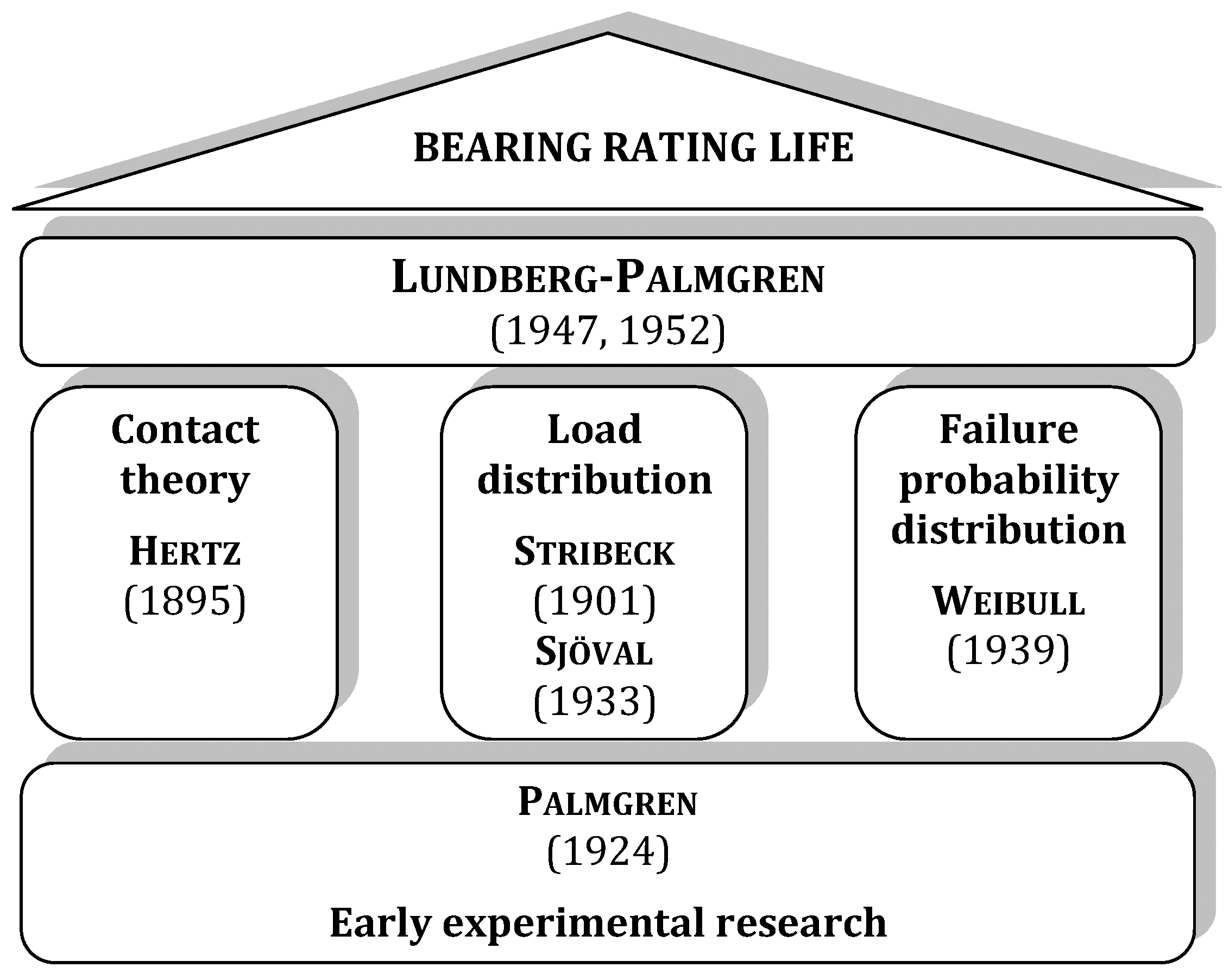
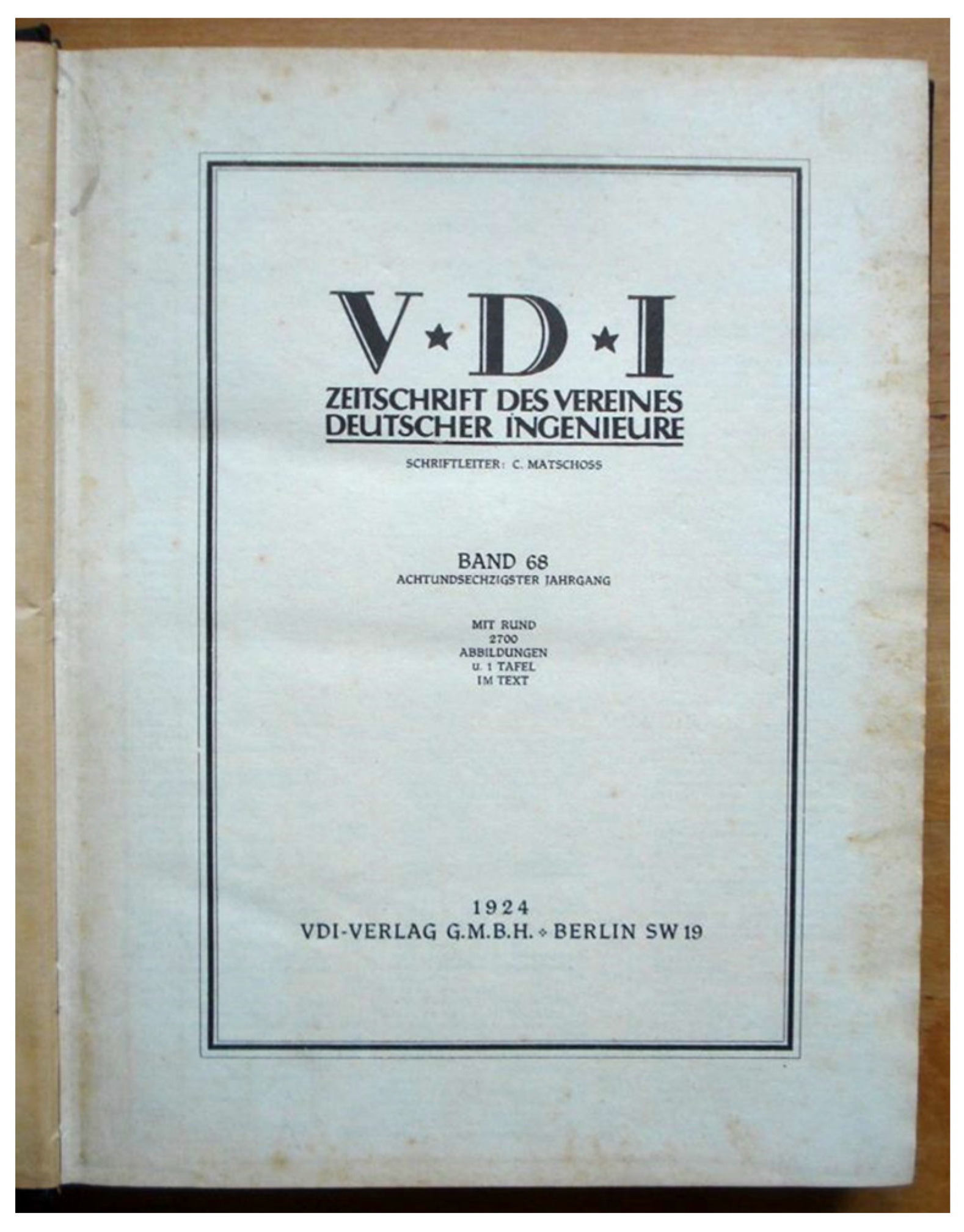
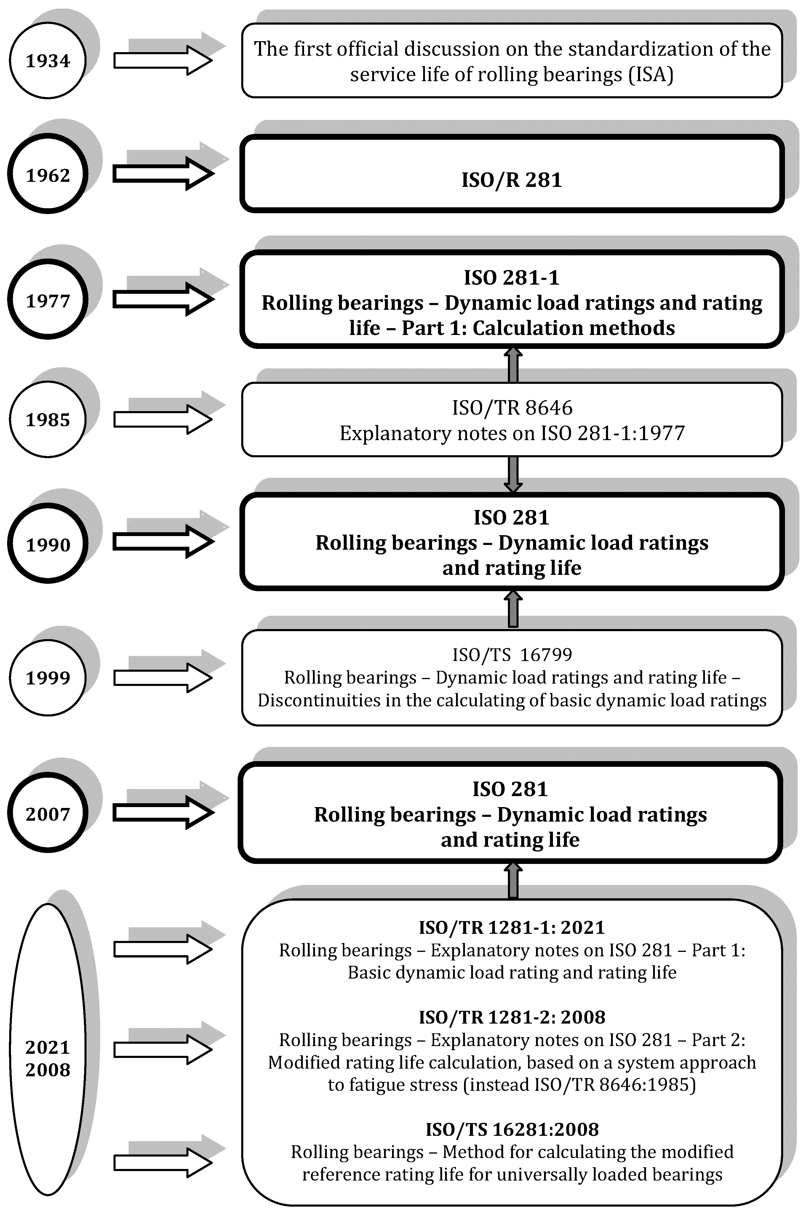
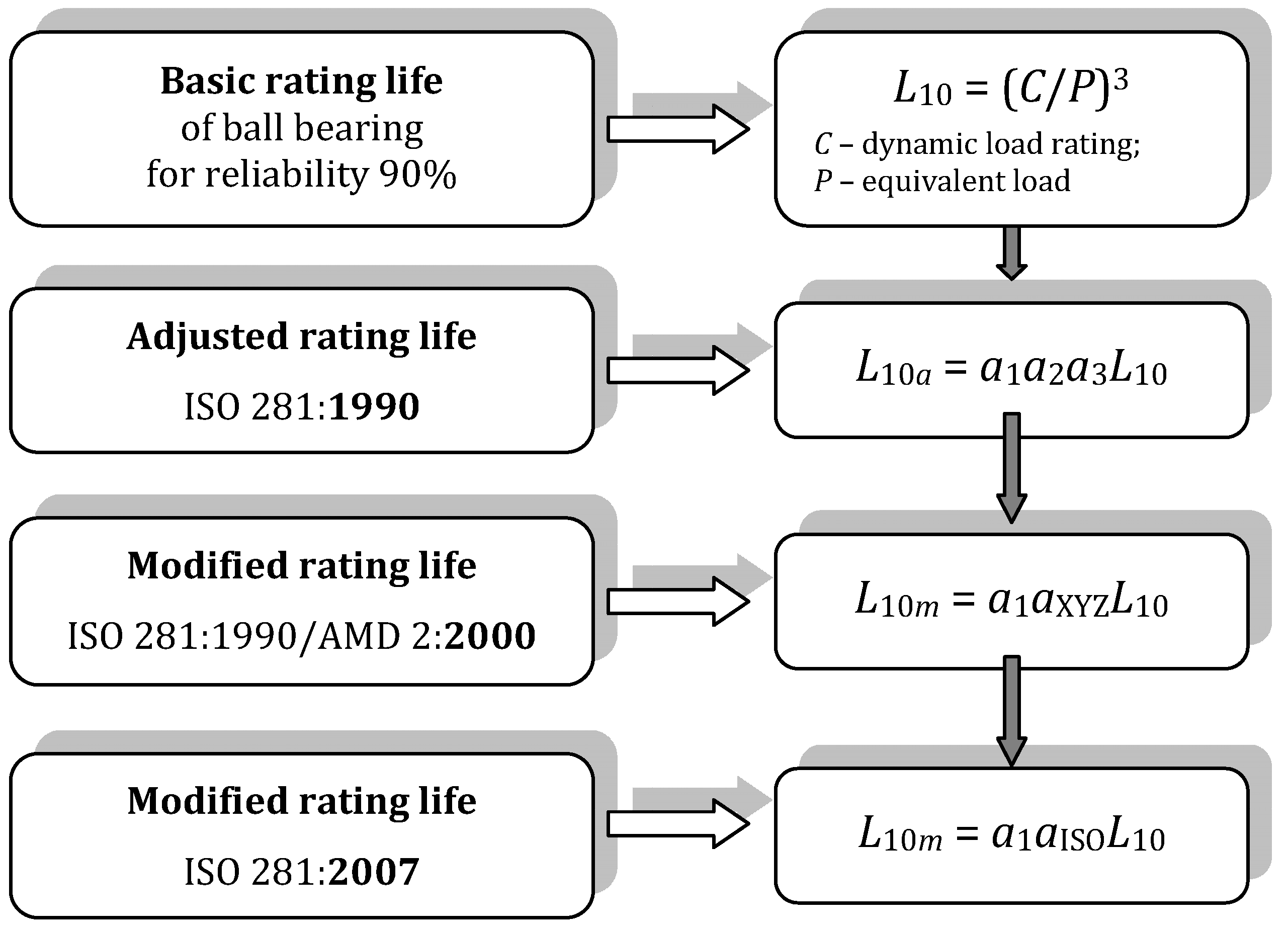
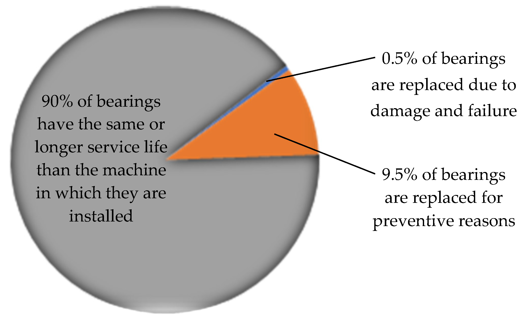


Disclaimer/Publisher’s Note: The statements, opinions and data contained in all publications are solely those of the individual author(s) and contributor(s) and not of MDPI and/or the editor(s). MDPI and/or the editor(s) disclaim responsibility for any injury to people or property resulting from any ideas, methods, instructions or products referred to in the content. |
© 2024 by the authors. Licensee MDPI, Basel, Switzerland. This article is an open access article distributed under the terms and conditions of the Creative Commons Attribution (CC BY) license (https://creativecommons.org/licenses/by/4.0/).