Abstract
The shearer is an important component of the smart mining workface, and its effective control is a key aspect that guarantees safe and high-efficient production in coal mines. To address the issue of autonomous height adjustment during the shearer’s cutting process, a self-adaptive speed control method driven by digital twin technology is proposed. A digital twin-based control architecture for the shearer is first established, which consists of physical and the corresponding virtual entities, as well as reality–virtual interaction between them. Based on the mathematic model formulated for height adjustment system of the shearer, an adaptive fuzzy sliding mode controller (AFSMC) with the displacement estimation is designed for the virtual entity, with the purpose of guiding the operation of the corresponding physical entity. Simulation experiments on MATLAB compares the control performance among the proposed method and four comparative ones, including PID controller, integral sliding mode controller (ISMC), feedback linearization controller (FLC), and fuzzy sliding mode controller (FSMC). The experimental results confirm the effectiveness of the proposed AFSMC. More specifically, its steady-state error is 0.024, the maximum absolute control input is 8.43, and the settling time is 1.74 s. This also proves that the digital twin-based control method enables the precise adaptive height adjustment of the shearer, providing potential reference for the intelligent development of a smart mining workface.
1. Introduction
Coal has been the most important fossil energy source globally for a long time. With the advent of the information age and the development of technology, the coal industry has undergone rapid transformation in equipment, processes, technologies, management, and modes. The mining workface, as the main scene of coal mining and one of the workplaces with a high concentration of personnel, the harsh production environment, numerous equipment, and low level of automation have become bottlenecks in the development and construction of coal mines. The smart mining workface is composed of intelligent individual devices, autonomous group equipment, and remote intelligent control technology [1]. The intelligent mining of coal holds significant importance for reducing labor, enhancing safety, and improving efficiency, representing a crucial task in the technological revolution of coal mining.
As a main coal mining equipment in the smart mining workface, the shearer performs two tasks: cutting and traction. In coal mines, coal is first cut from the coalfield by a shearer, and then carried away by a scraper conveyor. The roof after cutting is braced by hydraulic supports, avoiding its collapse. In order to improve mining efficiency, the above three equipment need to efficiently cooperate with each other. In particular, the displacement of the shearer shall be adjusted accurately in terms of the coal–rock interface, termed as height adjustment. During the production, due to the fluctuating distribution curve of the coal seam. The traditional mining mode maintains a fixed drum height on the coal shearer, which leads to significant damage to the cutting teeth. Frequent replacement of cutting teeth adversely affects the efficient production of coal mines [2,3]. Therefore, achieving adaptive height control for the shearer is an important problem that needs to be solved.
Tao [4,5] proposed a predictive and health management (PHM) system based on digital twin (DT) and introduced a five-dimensional DT model. Ge et al. [1] proposed the concept, architecture, and construction method of the digital twin smart mining workface system, which integrates 5G communication technology, Internet of Things (IoT) technology, and biomimetic intelligence technology to build a remote operation platform for smart mining workface. Guo et al. [6] proposed a new active control and management mode for virtual spaces to deeply mine and utilize knowledge from smart intelligent workface with digital twin. Yang [7] compared the neural network-based online self-learning adaptive PID control with a proportional–integral–derivative (PID) controller to improve the robustness and dynamic performance of shearer cutting height. Liu [8] designed a fuzzy controller based on the on/off time of an electromagnetic reversing valve to improve the steady-state performance of shearer drum height adjustment. Ruan [9] utilized the virtual simulation technology to solve shearer’s height adjustment control. Li [10] built a Grey–Markovian memory cutting algorithm after analyzing a traditional shearer memory cutting algorithm. Wang et al. [11] proposed an adaptive fuzzy reasoning Petri net (AFRPN) model based on fuzzy reasoning and fuzzy Petri net (FPN) and then applied it to the intelligent adjustment height of the shearer drum. Wang [12] established a DDPG control strategy that integrates environment perception, cutting, and control to improve the adaptability and accuracy of the shearer height adjustment system.
The above-mentioned research studies have conducted a large number of simulation analyses on the shearer. But in the actual production of the mining workface, there are still issues such as insufficient visualization, weak device interconnectivity, and slow information exchange. However, the digital twin system integrates intelligent sensing, collaborative simulation [13], and intelligent control technologies. It can effectively map the physical entity to the virtual one, which provides the prediction of the actions for the physical one. This achieves optimized equipment actions and precise control, providing valuable insights for the intelligent development of coal mines.
This main contribution of the article can be summarized as follows:
An architecture for digital twin-based height adjustment control of a shearer is constructed. We design the linear state estimator to estimate the displacement of the shearer accurately. And the adaptive fuzzy sliding mode controller is developed for adjusting the displacement of a shearer.
The rest of the article is organized as follows. The framework of digital twin-based height adjustment control for a shearer is illustrated in Section 2. The model of height adjustment system for a shearer is formulated in Section 3. The corresponding control method is presented and the experimental results are summarized in Section 4. Finally, the core idea is summarized and our future work is presented.
2. Digital Twin-Based Control Architecture for a Shearer
Digital twin technology involves creating virtual models of physical entities using digital methods [14]. The digital twin-based control system can be divided into four parts: the digital twin model, physical and virtual entities, as well as data interaction between them. Constructing a digital twin model by mathematical modeling methods, generating extensive twin data through dynamic simulation analysis, and building a virtual entity that replicates the physical one are the key issue. The virtual entity accurately identifies the equipment status of the shearer. By utilizing twin data analysis and combining controller design and algorithm optimization, it achieves predictive control of the equipment’s movements. The virtual entity guides the operation and maintenance of the physical entity, enabling virtual control over the real system.
Digital Twin Model: Sensors are used to collect data from the physical system, which are then utilized to construct a digital twin model. This so-called digital twin model is actually dynamic equations or state-space models of the controlled system obtained by mathematical modeling methods in terms of the monitoring data.
Virtual Entity: To address the control issue of the output, a linear state estimator is established, and a controller is designed based on the system’s dynamic equations or state-space model. Different types of controllers are simulated and verified, and the designed controllers are applied to the virtual one to evaluate their performance and stability by simulating the system’s dynamic response.
Data Interaction: The monitoring data collected from sensors are provided to virtual space for formulating and updating the mathematic models of height adjustment system. Also, some virtual data can be produced to enrich the number of those in specific classes with the purpose of improving the design for controller and fault diagnosis method.
Physical Entity: The validated controllers are applied to the digital twin platform. The control instructions from the virtual entity are issued to the physical system, enabling control of the physical equipment.
By constructing a digital twin architecture as shown in Figure 1, a foundation is laid for designing digital twin control methods. Through the model calculation and predictive analysis capabilities of the virtual entity, precise control and real-time feedback of the physical entity are achieved.
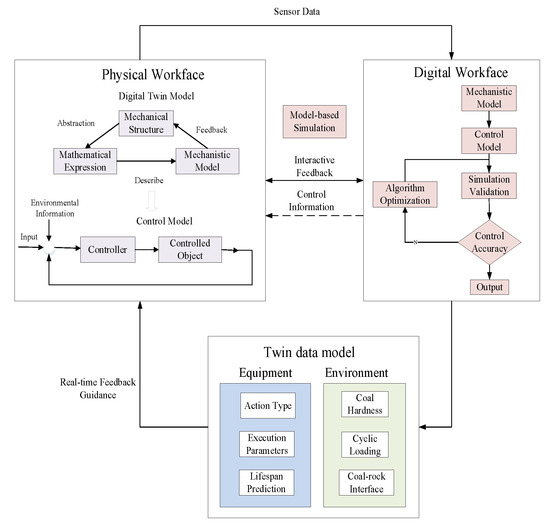
Figure 1.
Digital twin-driven control architecture of the smart mining workface.
3. Digital Twin Model for Height Adjustment of a Shearer
The components of the shearer for height adjustment include a drum, rocker arm, hydraulic cylinder for height adjustment, and hydraulic pipeline. Figure 2 displays the framework of its hydraulic control system by Amesim. To meet the requirements of load and dynamic stability during height adjustment, an electro-hydraulic proportional valve is generally used for automatic control of the coal mining machine’s height adjustment [15,16,17]. The hydraulic system usually uses a locking circuit composed of two hydraulic control one-way valves, which can lock the piston in any position. The height control system must withstand the impact load of the rocker arm and drum’s weight, as well as the cutting force during drum cutting operations. In order to adapt to changes in the thickness of coal seams in the smart mining workface, the direction and flow rate of the hydraulic fluid in the electro-hydraulic proportional valve are controlled to achieve the reciprocating movement of the hydraulic cylinder piston, completing adjustment of the height of the rocker arm and drum [18,19]. The parameters of the hydraulic valve are shown in Table 1.
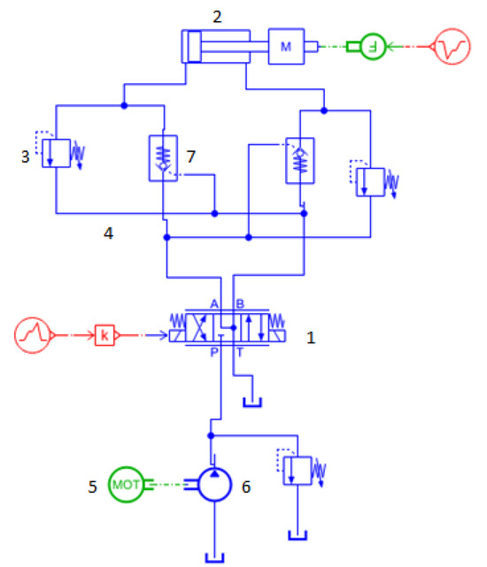
Figure 2.
Hydraulic system for height adjustment of the shearer: 1—electro-hydraulic servo valve, 2—hydraulic cylinder, 3—relief valve, 4—hydraulic pipelines, 5—motor, 6—pump station, 7—pilot valve.

Table 1.
The parameters of the hydraulic cylinder for height adjustment.
The load characteristics directly affect the dynamic characteristics of the piston when the hydraulic cylinder directly drives the load. When the input flow rate remains unchanged but the load changes, or the load remains unchanged but the input flow rate changes, the speed of the piston rod will change. Therefore, the flow equations for the two chambers of the height adjustment hydraulic cylinder are as follows:
The balance equation for the height adjustment hydraulic cylinder can be expressed as
Because ; therefore, the flow equation for the hydraulic cylinder can be expressed as
Ignoring the frictional effects of the height adjustment hydraulic cylinder, the oil pressure on the two sides of the hydraulic cylinder can be, respectively, expressed as
The pressure generated by compressing the hydraulic fluid can be expressed as
Because .
In the equation, S represents the total stroke of the height adjustment hydraulic cylinder, and is the stroke of the rodless chamber of the height adjustment hydraulic cylinder.
If , the minimum force exerted on the hydraulic cylinder can be obtained as follows:
Substituting Equation (8) into Equation (7) and ignoring the external leakage of the height adjustment hydraulic cylinder, we can obtain and make an approximation by considering the cross-sectional areas of both the piston and rodless chambers to be approximately equal. ; the corresponding flow equation and hydraulic cylinder balance equation can be obtained as follows:
Taking Equations (9) and (10) as the basis, we can perform Laplace transformation to obtain
Substituting Equation (11) into Equation (12), we can obtain the mathematical model for the height adjustment hydraulic cylinder as follows:
As the control actuator for the coal mining machine’s height adjustment system, the electro-hydraulic proportional directional valve adjusts the flow and pressure of the hydraulic oil by controlling the displacement of the actuating cylinder. The values of the parameters for the hydraulic valve are presented in Table 2. And the displacement of hydraulic valve are shown in Figure 3.
Table 2.
Parameters of hydraulic cylinder for height adjustment of a shearer.
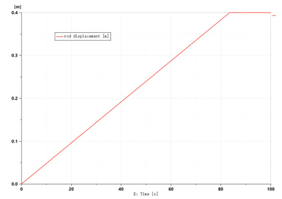
Figure 3.
Displacement of hydraulic cylinder for shearer height adjustment.
The height adjustment mechanism of a coal mining machine can be simplified as shown in Figure 4. The expression for the adjustment amount of the drum can be derived as follows:
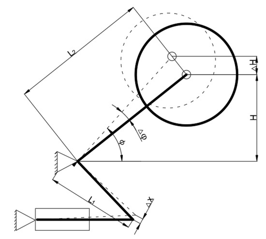
Figure 4.
Height adjustment mechanism of a shearer.
In the equation, L2 represents the length of the height adjustment mechanism rocker arm, represents the horizontal included angle of the rocker arm, and represents the change in the horizontal angle of the rocker arm. When the extension of the height adjustment cylinder is small, the extension amount of the cylinder rod is approximately considered as
In the above equation, L1 represents the length of the height adjustment mechanism’s small rocker arm. The expression for can be derived as follows:
Formula (17) can be expressed as :
By combining Formulas (17) and (18), we can obtain the following expression:
Formula (20) shows the relationship between the adjustment amount of the drum and the extension length of the actuating cylinder’s piston rod , and it can be expressed as follows:
The relationship between the displacement of the hydraulic cylinder and the adjustment displacement of the drum height, as depicted in Figure 5, exhibits a complex nonlinear relationship.
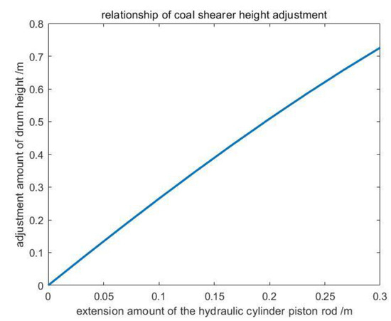
Figure 5.
Shearer height adjustment relationship.
4. Digital Twin-Based Height Control System for Coal Mining Machine
By analyzing the physical entity of the shearer height adjustment mechanism, a digital twin model of the height adjustment component is obtained. Within the virtual entity, a displacement estimator for the shearer height adjustment is designed to achieve the desired output of the height displacement. By employing adaptive laws and fuzzy systems to optimize uncertainties, an adaptive sliding mode controller is designed to achieve autonomous control of the shearer height adjustment [20,21]. The structure of the adaptive fuzzy sliding mode control system for the shearer height control is shown in Figure 6. Once the shearer cut through rock seams, dynamics of the shearer changes over time and the control performance may become worse. Thus, the controller parameters shall be updated in virtual space by adaptive law.
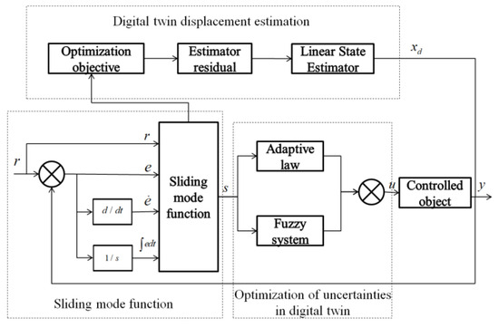
Figure 6.
Structure of digital twin-based displacement controller for a shearer.
4.1. Digital Twin-Based Displacement Estimation for Height Adjustment
After the sensor transmits the data, a digital twin system can be used to simulate the internal signals of the feedback system [22]. By using a linear observer, it can overcome uncertainty in initial conditions and estimate the displacement of the actuating cylinder when combined with a sliding mode controller.
A displacement sensor is used to directly measure the adjustment displacement of the drum height. However, due to the influence of friction, the displacement of the actuating cylinder is not equal to the adjustment displacement of the drum height. A nonlinear estimator can be employed to compensate for this discrepancy. The structure diagram of the estimator is as shown in Figure 7:
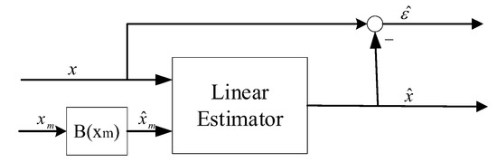
Figure 7.
Displacement estimation of a shearer based on digital twin.
The dynamics of the lifting cylinder is formulated as follows.
where Ts represents the sampling time and xm is its input. The transfer function of the lifting cylinder with the output, x, can be expressed as follows:
By defining e as the estimator output and using as the estimator residual, the goal is to minimize the estimation residual value:
The minimization problem should be an unbiased estimator. To ensure the minimizer is unbiased, a linear state estimator is proposed to eliminate the influence of initial conditions. The weight vector of the linear estimator is chosen to attenuate the linear estimation error in less than kTs seconds. The solution of the nonlinear minimization problem can be obtained using various well-known minimization algorithms and implemented with the help of a digital twin platform. These algorithms can simulate the estimator faster than real-time.
4.2. Fuzzy System Design
By establishing a mathematical model of the controlled object, a sliding mode controller can enable the system output to directly track the desired command. However, due to modeling uncertainties, larger gains may be required, leading to chattering phenomena. Due to the approximation capability of fuzzy systems, combining sliding mode control with fuzzy systems for nonlinear control approximation can effectively reduce fuzzy gains. Adaptive laws can be derived using the Lyapunov method, and adjusting the adaptive weights can ensure stability and convergence of the closed-loop system.
Due to the unknown resistance from coal or rock on the coal mining machine [23], is approximated by . For the inputs and of the fuzzy system, we design five fuzzy sets each. The fuzzy rules are constructed as follows:
Step 1: For variables ti, i = 1 or 2, define fuzzy sets , = 1, 2, 3, 4, 5.
Step 2: Use to construct the fuzzy system with a total of 25 fuzzy rules, the fuzzy rules can be expressed as follows:
: IF is and is . Then, is = 1, 2, 3, 4, 5, i = 1, 2, j = 1, 2…, 25, . For the fuzzy set of the conclusion.
The four steps for fuzzy reasoning are as follows:
1. Using the product inference engine to perform premise reasoning for the rules, the inferred result is
2. Using a singleton fuzzifier to calculate , which is the function value of the abscissa value corresponding to the maximum membership value (1,0) of the membership function.
3. Using the product inference engine to perform reasoning on the premise and conclusion of the rules, the inferred result is . For all the fuzzy rule operations, the corresponding output is obtained as .
4. Using the average defuzzifier, the output of the fuzzy system is obtained as
The membership function of is .
Let be a free parameter in the set , and introduce the fuzzy basis vector . Then, the output becomes
is the 25-dimensional fuzzy basis vector, with the element being
4.3. Adaptive Fuzzy Sliding Mode Controller
By modeling the double-drum shearer, the sliding mode controller can make the output of the system track the desired signal. By selecting the shearer height displacement, height velocity, and height acceleration as the state variables of the system, represented as , the uncertain system of shearer height displacement can be expressed using Equation (28):
where u is the input of controller. represents the cutting resistance disturbance of the shearer. The coefficients of the above model is defined as follows:
In addition,
The sliding mode function is defined as follows:
where 1 < p < 2. represents the tracking error between the monitoring value and reference signal.
Differentiating Equation (30) with respect to xd and xm, we obtain
To ensure the system reaches a stable state, we take the Lyapunov function as
In addition, , where represents the observed value of the shearer’s coal stacking resistance, and represents its estimation error. The optimal parameters are denoted as
In addition, the set is equal to the set .
represents the approximation error of the fuzzy system.
Substituting Equation (36) into Equation (33), we have
The adaptive law is obtained as
Substituting the adaptive law into Equation (37), we have
The control input u is designed as follows:
Therefore, substituting the control law u into Equation (37), we have
Because , the system is stable. Here, > 0.
4.4. Simulation Analysis
In order to verify the effectiveness of adaptive fuzzy sliding mode controller (AFSMC) proposed in the article, four commonly used control methods [20], including PID, ISMC, FLC, and FSMC controllers, are employed for performance comparison by simulation experiment in Matlab. The mathematical model of the shearer for experiment is derived from the above-mentioned digital twin model. The simulation of the controllers were compared as shown in the Figure 8.
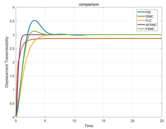
Figure 8.
Response curves of comparative controllers.
- (1)
- PID controller
- (2)
- ISMC controller
The integral sliding surface is defined as
Then, control input is
- (3)
- FLC controller
The sliding surface is defined as
Then, control input is
- (4)
- FSMC controller
The sliding surface is defined as
Then, control input is
The performance of the controllers is compared in Table 3. We use three indexes: steady-state error, settling time, and maximum absolute control input. The AFSMC method exhibited the fastest settling time. Figure 9 and Figure 10 illustrate the tracking error and control input for all compared control methods. The steady-state performance is compared using steady-state error and control input. The adaptive fuzzy sliding mode controller demonstrated superior stability and robustness.
Table 3.
Performance index of five control methods.
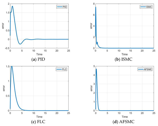
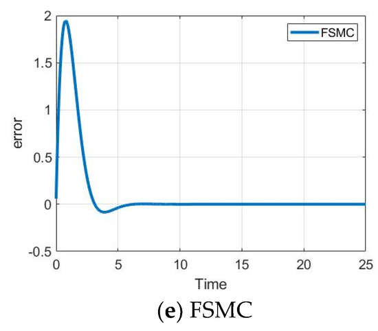
Figure 9.
Tracking error of comparative controllers.
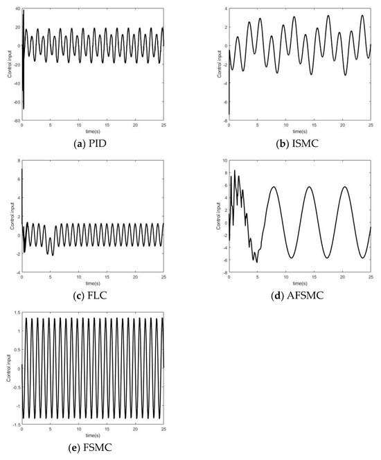
Figure 10.
Control inputs of comparative controllers.
5. Conclusions
This article establishes the digital twin-based control architecture and method for the shearer by utilizing the decision control technology of the virtual entity to guide the operation and maintenance of the physical entity. It builds a digital twin model for the shearer’s lifting mechanism and research on the correlation between the displacement of the coal mining machine’s lifting hydraulic valve and the lifting amount of the drum. It designs a displacement estimator and an adaptive fuzzy sliding mode controller for the shearer’s lifting mechanism. Fuzzy systems are used to optimize uncertain variables, and the system’s stability is verified using the Lyapunov function method. AFSMC is compared with PID, ISMC, FLC, and FSMC, and it is found that AFSMC designed by the digital twin system has the highest accuracy and requires smaller adjustment inputs. These results validate the superiority and accuracy of the digital twin control method.
Author Contributions
Conceptualization and methodology, X.Y.; software and validation, X.Y.; formal analysis and investigation, Y.G.; resources and data curation, B.M.; writing—original draft preparation and writing—review and editing, X.Y.; visualization and supervsion, S.G. All authors have read and agreed to the published version of the manuscript.
Funding
This research was funded by the Natural Science Foundation of China (Major Program), grant number 52121003.
Data Availability Statement
The data presented in this study are available on request from the CHN Energy Investment Group.
Conflicts of Interest
The authors declare no conflicts of interest.
References
- Ge, S.R.; Zhang, F.; Wang, S.B.; Wang, Z.B. Digital twin for smart coal mining workface: Technological frame and construction. J. China Coal Soc. 2020, 45, 1925–1936. [Google Scholar]
- Wang, G.F.; Liu, F.; Meng, X.J. Research and practice on intelligent coal mine construction (primary satge). Coal Sci. Technol. 2019, 47, 1–36. [Google Scholar]
- Zhang, C.; Wang, P.; Wang, E.; Chen, D.; Li, C. Characteristics of coal resources in China and statistical analysis and preventive measures for coal mine accidents. Int. J. Coal Sci. Technol. 2023, 10, 22. [Google Scholar] [CrossRef] [PubMed]
- Tao, F.; Zhang, M.; Liu, L.S.; Nee, N.Y.C. Digital twin driven prognostics and health management for complex equipment. Cirp Ann. 2018, 67, 169–172. [Google Scholar] [CrossRef]
- Xiang, F.; Zhou, S.; Zuo, Y.; Tao, F. Digital Twin Driven End-Face Defect Control Method for Hot-Rolled Coil With Cloud-Edge Collaboration. IEEE Trans. Ind. Inform. 2023, 19, 1674–1682. [Google Scholar] [CrossRef]
- Guo, Y.N.; Yang, F.; Ge, S.R.; Huang, Y.; You, X.S. Novel Knowledge-driven Active Management and Control Scheme of Smart Coal Mining Face with Digital Twin. J. China Coal Soc. 2023, 48, 334–344. [Google Scholar]
- Yang, T.M.; Xiong, S.B. Neural network based online self-learning adaptive PID control for automatic ranging cutting height of shearer. Proc. Int. Conf. Mach. Learn. Cybern. 2002, 2, 857–859. [Google Scholar]
- Liu, C.S.; Yang, Q.; Li, C.H. Simulation of shearer drum cutting with memory program controlling by fuzzy control. J. China Coal Soc. 2008, 7, 822–825. [Google Scholar]
- Ruan, J.X.; Liu, X.N.; Zhao, L.J. Study on the Height Adjusting Control System of Shearer Based on Virtual Simulation Technology. In Proceedings of the International Conference on Control Engineering and Automation, Chongqing, China, 29–30 November 2014. [Google Scholar]
- Li, W.; Fan, Q.G.; Wang, Y.Q. Adaptive height adjusting strategy research of shearer cutting drum. Acta Montan. Slovaca 2011, 16, 114–122. [Google Scholar]
- Wang, W.B.; Wang, S.Q.; Zhao, S.F.; Lu, Z.X.; He, H.T. Novel intelligent adjustment height method of Shearer drum based on adaptive fuzzy reasoning Petri net. J. Intell. Fuzzy Syst. 2022, 42, 1767–1781. [Google Scholar] [CrossRef]
- Wang, Y.D.; Zhao, L.J.; Zhang, M.C. Research on self-adaptive height adjustment control strategy of shearer. J. China Coal Soc. 2022, 47, 3505–3522. [Google Scholar]
- Zhang, Q.; Chen, H.; Zhu, Y.G.; Wang, J.Y.; Zhou, C.Z. Digital Twin Based on 3D Visualization and Computer Image Recognition Technology in Coal Preparation Plant. J. Phys. Conf. Ser. 2021, 2083, 042068. [Google Scholar] [CrossRef]
- Zhang, H.; Qi, Q.L.; Tao, F. A consistency evaluation method for digital twin models. J. Manuf. Syst. 2022, 65, 158–168. [Google Scholar] [CrossRef]
- Li, X.H.; Hu, Y.T.; Chi, Q.D.; Bai, S.W. Constant Power Speed-adjusting of Shearer Cutting Motor by Single Neuron Self-adaptive PID Controlling. Appl. Mech. Mater. 2012, 190, 856–859. [Google Scholar] [CrossRef]
- Ding, F.; Li, B.B.; Zhang, H.N. Cutting Constant Power Speed-Adjusting Control System of Electrical Haulage Shearer Based on Rbf Neural Network Pid Control; CNAI: Beijing, China, 2018. [Google Scholar]
- Tan, C.; Xu, R.; Wang, Z.B.; Si, L.; Liu, X.H. An Improved Genetic Fuzzy Logic Control Method to Reduce the Enlargement of Coal Floor Deformation in Shearer Memory Cutting Process. Comput. Intell. Neurosci. 2016, 2016, 3973627. [Google Scholar] [CrossRef]
- Liu, Y.G.; Hou, L.L.; Qin, D.T.; Zhang, Y. Self-adaptive control of shearer based on cutting resistance recognition. Int. J. Adv. Manuf. Technol. 2018, 94, 3553–3561. [Google Scholar] [CrossRef]
- Rezvani, S.; Kim, C.-J.; Park, S.S.; Lee, J. Simultaneous Clamping and Cutting Force Measurements with Built-In Sensors. Sensors 2020, 20, 3736. [Google Scholar] [CrossRef]
- Zhang, Z.; Guo, Y.N.; Gong, D.W.; Zhu, S. Hybrid extended state observer-based integral sliding mode control of the propulsion for a hydraulic roofbolter. Control Eng. Pract. 2022, 126, 105260. [Google Scholar] [CrossRef]
- Wang, H.; Lu, Y.; Tian, Y.; Christov, N. Fuzzy sliding mode based active disturbance rejection control for active suspension system. Proc. Inst. Mech. Eng. Part D J. Automob. Eng. 2020, 234, 449–457. [Google Scholar] [CrossRef]
- Yoav, V.; Stephen, J.E. The use of digital twins to remotely update feedback controllers for the motion control of nonlinear dynamic systems. Mech. Syst. Signal Process. 2023, 185, 109770. [Google Scholar]
- Yang, Y.; Fan, H.; Ma, P. Research on dynamic characteristics for longwall shearer cutting transmission system with varying cutting speed. Int. J. Precis. Eng. Manuf. 2017, 18, 1131–1138. [Google Scholar] [CrossRef]
Disclaimer/Publisher’s Note: The statements, opinions and data contained in all publications are solely those of the individual author(s) and contributor(s) and not of MDPI and/or the editor(s). MDPI and/or the editor(s) disclaim responsibility for any injury to people or property resulting from any ideas, methods, instructions or products referred to in the content. |
© 2024 by the authors. Licensee MDPI, Basel, Switzerland. This article is an open access article distributed under the terms and conditions of the Creative Commons Attribution (CC BY) license (https://creativecommons.org/licenses/by/4.0/).