Abstract
Rubbing between a blade and its coated casing is one of the main failures in aero-engine systems. This paper aims to study the effects of coated casings on rubbing-induced dynamic responses considering the flexibility of the coated casing and the flexibility of the blade. Firstly, an actual compressor blade is established by the shell element and verified by the experiment and ANSYS 19.2 software. Subsequently, a new dynamic model for the coated casing is proposed based on the laminated shell element, and the proposed dynamic model for the coated casing is verified by comparing the natural characteristics calculated by ANSYS software. Moreover, a comprehensive analysis is conducted to analyze the influences of the casing model, coating parameters, and casing parameters on vibration characteristics. Finally, the results show that the coating can diminish the severity level of rubbing. Notably, the material and thickness of the coating can change the nodal diameter vibrations of the casings (NDVCs) induced by rubbing. This study provides valuable guidance for the optimization and design of blade–casing systems.
1. Introduction
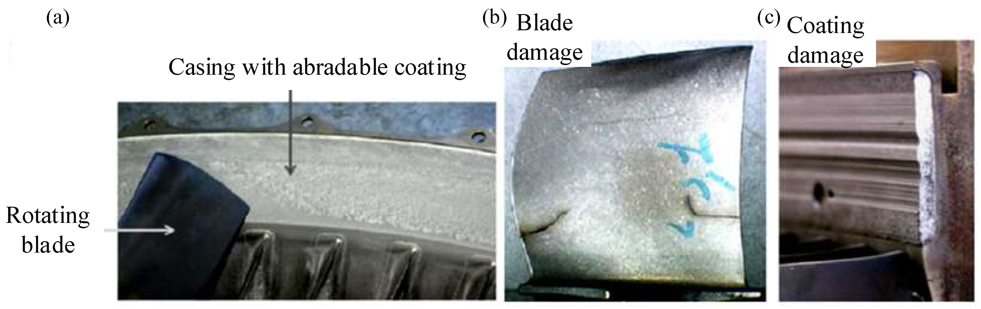
To enhance engine efficiency by changing airtightness, the radial clearance between blades and casings has been gradually reduced [1,2,3]. However, this reduction has aroused the issue of blade–casing rubbing faults, further resulting in economic losses and catastrophic accidents. Technological advancements have led to the application of coatings on the casing to enhance wear resistance and reduce vibration induced by rubbing. Consequently, attention has gradually shifted from blade–casing rubbing to the blade-coated casing, and the latter has become a main concern in aero-engine operation. Rubbing may have adverse effects on blades and casings, as depicted in Figure 1. Consequently, a comprehensive analysis of blade-coated casing rubbing is important to ensure the secure operation of aero-engines.
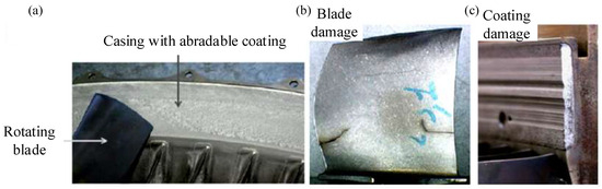
Figure 1.
Schematic of a blade–casing system and the hazards induced by rubbing: (a) blade-coated casing system, (b) blade damage in Ref. [4]; (c) coating damage in Ref. [5].
The dynamic modeling of blades has been a prominent focus in recent decades, with a variety of approaches using the finite element (FE) method, such as the cantilever beam model [6,7,8,9,10,11,12,13,14,15,16], the cantilever plate model [17,18,19,20,21,22], the shell model [23,24,25,26,27,28,29,30,31], and the solid element model [32,33,34,35,36]. It is a challenge to accurately capture the true morphological characteristics of compressor blades when beam element models are employed. Although the solid element model can compensate for this shortcoming, the use of solid elements often results in lower computational efficiency. Hence, the adoption of shell element modeling emerges as a compromise. Based on the shell element, various researchers have made significant contributions to the establishment of dynamic models for rotating blades. For instance, Sinha and Zylka [23] derived the control differential equation for rotating pre-twisted airfoil blades, transforming it into matrix eigenvalue form using the Rayleigh–Ritz method. Sun et al. [24] proposed a modeling method for pre-twisted rotating blades based on shell theory and the Hamilton principle, and they studied the vibration characteristics under different stagger angles and rotational speeds. Kee and Shin [26] developed a modeling approach using composite blades with a mixed element, combining an eight-node solid element with a shell element. Yangui et al. [27] used a three-node triangular shell element with six degrees of freedom to conduct the dynamic modeling of blades. Rafiee et al. [29] used the Shell99 element to establish an FE model of fan blades and focused on the study of the aeroelastic characteristics of blades. Kee and Kim [30] established an FE model for pre-twisted rotating composite blades using a degenerated shell element with nine nodes. They studied the effects of composite material lamination and fiber orientation parameters on the dynamic characteristics of blades. Additionally, Xiong et al. [31] utilized shell elements to establish a dynamic model for actual compressor blades and analyzed crack-induced characteristics. The aforementioned literature underlines the maturity of employing shell elements in blade modeling. Thus, based on our previous study (Ref. [31]), shell elements are utilized to establish compressor blades to investigate the rubbing fault of compressor-blade-coated casings in this paper.
There is a great deal of interest in the modeling of casings for blade–casing systems, with the lumped-mass model and FE model being approaches of interest. To simplify calculations, casings are built by the lumped-mass method. For instance, Sinha [37] simplified the casing as a lumped-mass point and investigated the transient dynamic response considering rubbing. Ma et al. [38] developed an FE model of a rotor–rigid casing and analyzed the vibration response induced by rubbing, and the casing was considered as the lump-mass point. While such simplified models serve certain analytical purposes, the actual casing, which is a thin shell structure, undergoes local deformation due to rubbing. Therefore, the accurate modeling of casings needs to consider casing flexibility. Zeng et al. [39] used Timoshenko beam elements to establish an FE model of casings and studied rubbing-induced dynamic responses. Lesaffre et al. [40] studied the stability of a rotating beam-flexible casing considering rubbing based on the Routh–Hurwitz criterion. Guo et al. [41] introduced an elastic-supported casing model according to the Sanders shell theory and mainly investigated the rubbing-induced vibration response of casings. Zeng et al. [42] also proposed a modeling approach of a rotor-disk-flexible casing considering elastic support using ANSYS/LS-DYNA software. In particular, Batailly and Legrand [43] analyzed the vibration response caused by the unilateral contact between blades and flexible casings based on the contact algorithm. In the context of coated casings, which are prevalent in modern aero-engine designs, more attention is paid to composite casings [44,45,46,47,48,49,50,51]. To enhance calculation accuracy, the FE method is widely employed to establish composite cylindrical shells (i.e., coated casings). For example, Zhang et al. [49,50] used a four-node shell element to conduct the dynamic modeling of a hard-coated cylindrical shell and investigated nonlinear vibration characteristics considering the base excitation. Additionally, Khan et al. [51] also studied the dynamic characteristics of laminated cylindrical shells via the FE method. Despite these advancements, the literature indicates a need for further exploration into utilizing more accurate shell elements in building dynamic models of coated casings. The development of coated casing models using the finite shell element method is still a field worthy of further research to improve accuracy and reliability.
In addition, scholars have also turned their attention to the study of the rubbing dynamic response in blade–casing systems. For example, Ma et al. [52,53] considered the bending deformation of blades and established an improved normal rubbing force model. Zhou et al. [54] investigated rubbing-induced vibration characteristics and found that harmonic frequencies near the natural frequency are more susceptible to the effect of rubbing. Hou et al. [55] analyzed frequency modulation considering rubbing in a rotor system and proposed an indicator to evaluate the severity of rubbing. Wu et al. [56] established a dynamic model with large rotation in a rotor-blade system and found the natural frequency in the spectrum. Shao et al. [57] also investigated the vibration characteristics caused by looseness and rubbing. Li et al. [58] proposed a rubbing model considering the local deformation of the casing during the rubbing process and studied the vibration characteristics of casings. Yang et al. [59,60,61] proposed a novel hysteresis force model to characterize contact force and studied the bending–torsional coupling vibration of the blade–casing system under non-uniform initial clearance conditions. Zeng et al. [62] primarily analyzed the rubbing-induced dynamic responses of blades. However, casing vibration has not received substantial attention in Refs. [63,64,65,66,67,68,69,70]. Although the vibration of an uncoated casing was considered in our previous paper [41], coatings can alter the natural characteristics of a casing and affect the dynamic response. Notably, coating wear has garnered significant attention, including in relation to the wear process [71,72,73], blade–coating interactions [74,75,76], wear models [77,78], and so on. While current research on blade–casing rubbing predominantly analyzes the vibration characteristics of blades, that of casing is often overlooked. Although the rubbing-induced dynamic response of blade–casing systems has gained widespread attention, it is essential to shift focus towards the vibration characteristics of coated casings and the effect of coatings on rubbing, with regard to coating material, coating thickness, etc.
The primary motivation of this paper is to study the rubbing-induced dynamic responses in a blade-coated casing system. The following contributions are listed in this paper on the basis of previous works: (1) A modeling method of the coated casing is developed based on laminated shell elements. Subsequently, a dynamic model of the system with rubbing is established. (2) The influence of the casing model (lumped-mass model, cylindrical shell model, and laminated casing model) and casing parameters (casing support stiffness and casing length) on the dynamic response of the system is systematically analyzed. (3) Notably, this study delves into the analysis of the effects of coatings on dynamic responses considering rubbing, including coating thickness and coating materials. In summary, this article primarily focuses on the response of coated casings and explores the influence of coatings on rubbing-induced dynamic responses, providing valuable insights into the field.
The layout of this article is organized as follows: The establishment of the model is described in Section 2, including blade dynamic modeling, casing dynamic modeling, rubbing force modeling, and system dynamic modeling. Section 3 mainly includes numerical simulation analyses, such as a comparison of casing models and investigations into the influence of coating parameters and casing parameters. Finally, Section 4 displays some conclusions.
2. Dynamic Modeling of the Blade-Coated Casing System with Rubbing
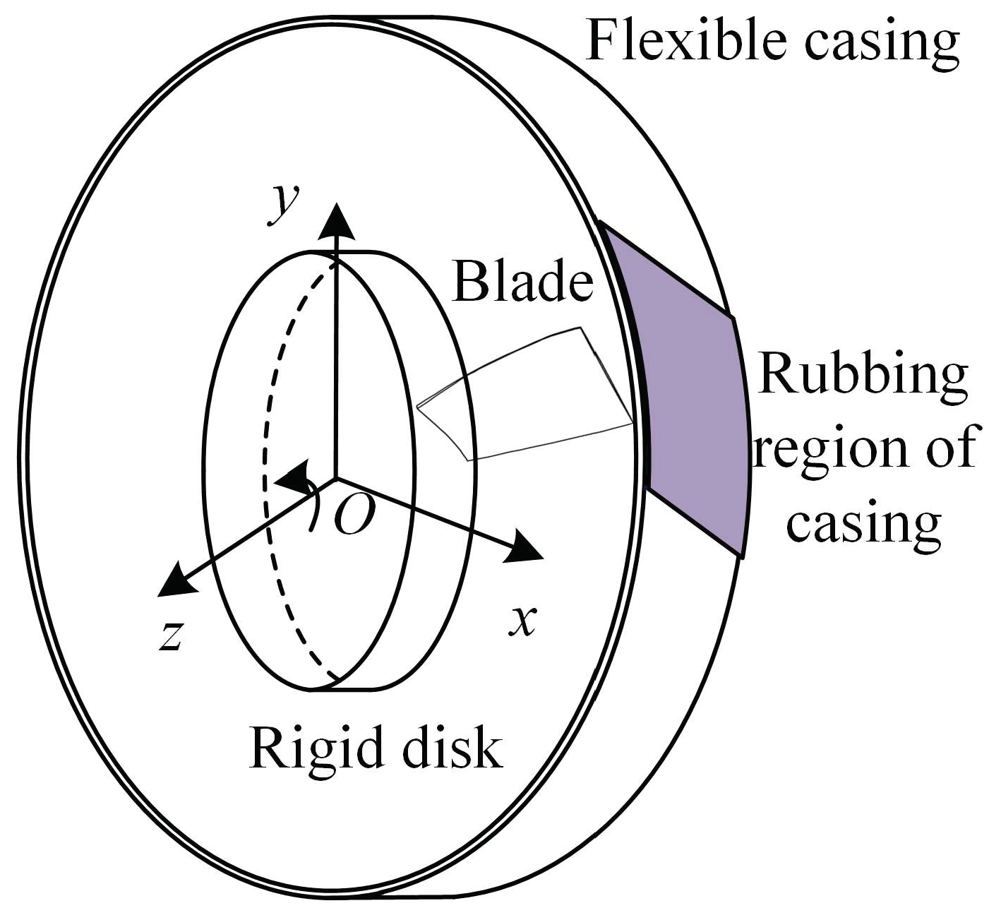
The dynamic model proposed is displayed in Figure 2. Its main components include blade dynamic modeling, casing dynamic modeling, and so on. Throughout the modeling process, several assumptions are considered as follows:
- (1)
- Similar to Ref. [59], coating wear and temperature effects are not considered when rubbing occurs.
- (2)
- The origin of the coordinate system is located at the center of mass of the rigid disk.

Figure 2.
Schematic of the flexible blade–casing system.
Figure 2.
Schematic of the flexible blade–casing system.
2.1. Dynamic Model of the Blade
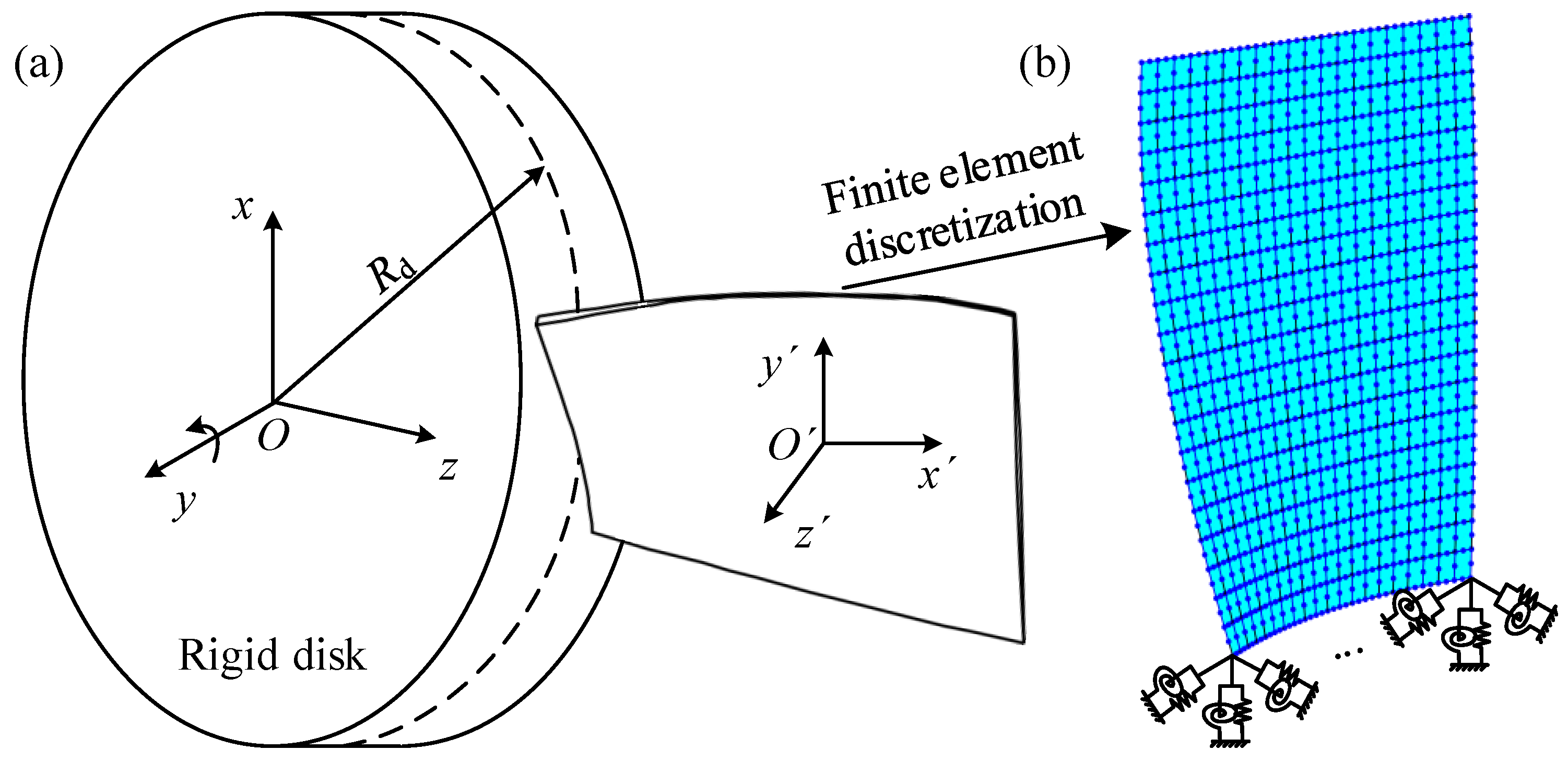
The compressor blade is shown in Figure 3 and the blade is established by the FE method. To accurately describe the blade shape, a three-dimensional shell element with eight nodes is used to establish the FE model of the blade. This FE model has a total of 400 (20 × 20) elements. Oxyz and O’x’y’z’ are the global and local coordinate systems, respectively. Rd represents the radius of the rigid disk.
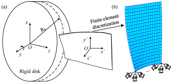
Figure 3.
Schematic of rotating blades and FE model: (a) schematic; (b) FE model.
On the basis of Ref. [31], the dynamic model of the blade is built. Detailed parameters can be found in Ref. [31]. A spring element is applied at each node of the blade root to simulate the elastic support, as depicted in Figure 3. It is essential to note that the shell element possesses only five degrees of freedom. Consequently, the last torsional stiffness of the spring element is filled with zero N·m/rad. Consequently, the differential equation of motion of the blade with elastic support is written as
where M, C, G, Ke, Kce, Kco, and Ks represent the mass, damping, Coriolis force, structure stiffness, centrifugal stiffening, elastic support stiffness, and spin softening matrixes of the blade. Detailed modeling processes and descriptions are displayed in Appendix A. In this paper, the stiffness of springs to simulate the elastic support is calculated and the results are found to be kx = 4.001 × 10⁸ N/m, ky = 4.61 × 10⁷ N/m, kz = 1.997 × 10⁸ N/m, kθx = 1.437 × 10¹¹ N·m/rad, and kθy = 2.118 × 10¹⁰ N·m/rad during the analysis process in Section 3.
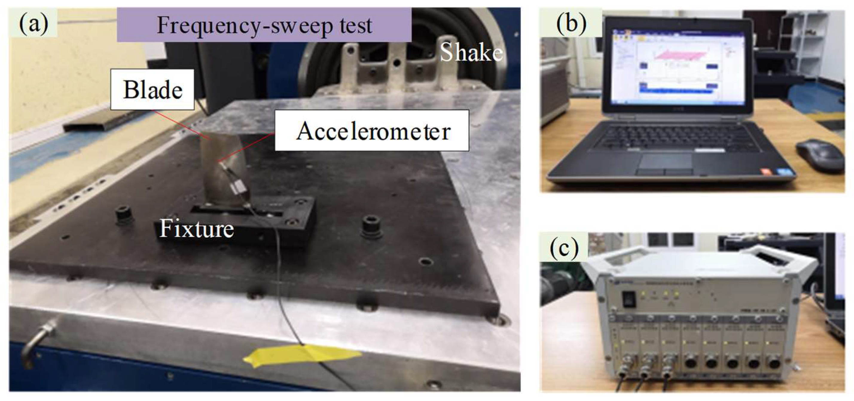
The proposed model of the compressor blade is verified through comparisons of natural frequency, which is determined through the frequency-sweep experiment, as shown in Figure 4. Additionally, ANSYS software is also employed to calculate the natural frequency. Throughout the experiment, the blade is securely fixed in the electromagnetic excitation shake by the fixture and an accelerometer is placed in the middle of the blade to measure the vibration signal. The vibration signal is collected by the DH5956 data acquisition instrument and the mobile workstation is used to process the collected data. By applying loads with different frequencies, the response amplitude is amplified if the resonance phenomenon occurs. The frequency approximately corresponds to the natural frequency of the blade.

Figure 4.
Test rig for measuring natural frequencies [31]: (a) test bench; (b) mobile workstation; (c) DH5956 data-collecting and -processing system.
The comparative results of the first three natural frequencies (NFs) of the blade are listed in Table 1. All frequency errors are less than 5%. This verifies the proposed dynamic model of the blade. Sources of error are analyzed as follows: (1) Material property errors: Physical properties of materials, such as elastic modulus, density, and Poisson’s ratio, may have measurement errors or variability. (2) Geometric dimension errors: The geometric dimensions used in the model (such as thickness, length, width, etc.) may deviate from the actual dimensions. (3) Boundary condition errors: The boundary conditions applied in the simulation (for example, constraints) may differ from the actual conditions. (4) Manufacturing errors: Tolerances in the manufacturing process can cause the actual dimensions of structural components to differ from the design dimensions. (5) Numerical errors: Approximation and rounding errors are induced in numerical calculations.

Table 1.
The first three NFs of the blade with fixed support.
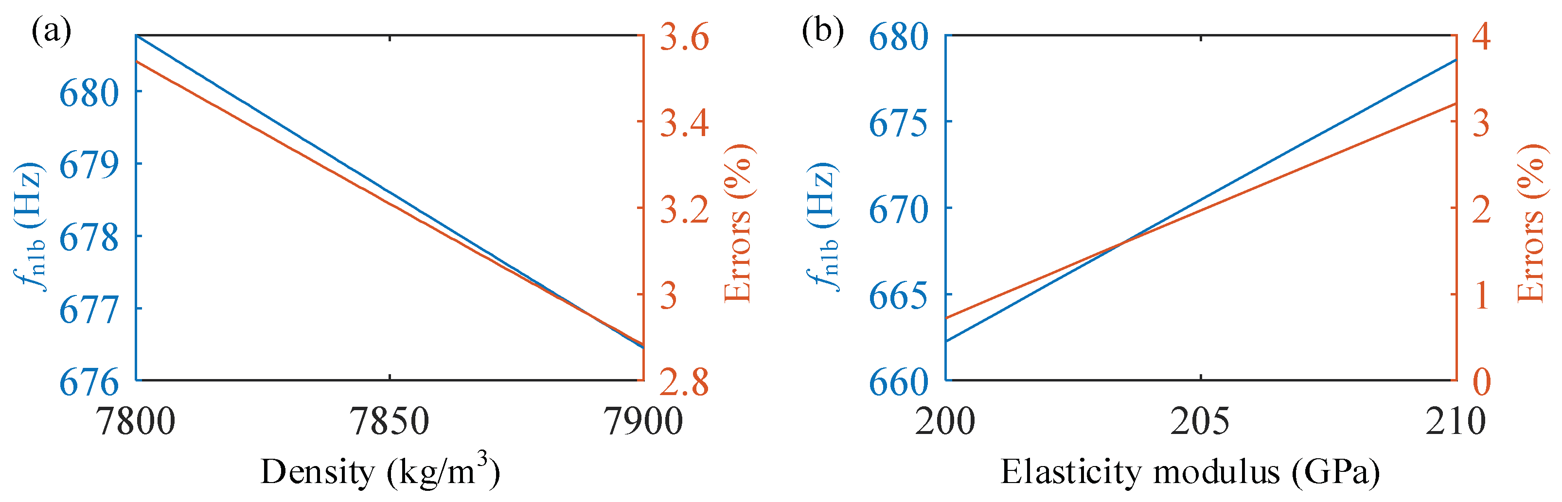
It is difficult to guarantee the same elastic modulus and density in a simulation and an experiment. Thus, these two typical parameter errors are analyzed, as shown in Figure 5. As the density increases, the first natural frequencies of the blade and error linearly decrease. However, with the increase in elasticity, the first natural frequencies of the blade and error increase linearly.
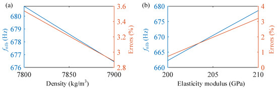
Figure 5.
Study of the influence of parametric errors: (a) the influence of density, (b) the influence of elasticity modulus.
2.2. Dynamic Model for the Coated Casing
Although the lumped-mass modelling of casings can improve computational efficiency, it fails to consider the local deformation of the casing and potentially leads to errors in calculating the radial clearance at the blade tips. Thus, the laminated shell element is introduced to establish the FE model for flexible coated casings. By defining the distinct material parameters of each casing layer, the stiffness and mass matrices of laminated shell elements are calculated.
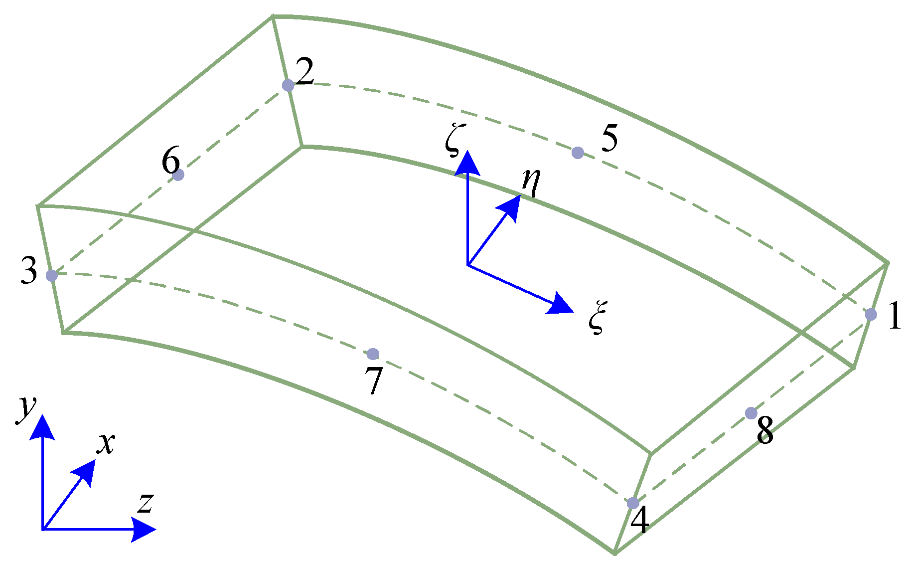
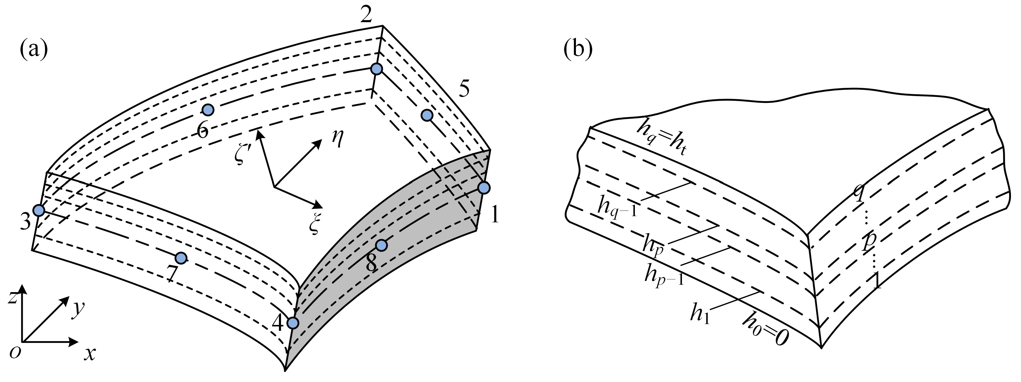
Within the laminated shell element, material parameters change in the thickness direction. This leads to different densities, strain matrices, and elastic matrices in different layers. Consequently, when calculating the mass and stiffness matrices of the laminated shell element, integration by parts is employed for precision. To simplify the computation process, a new local coordinate system ξηζ′ is established in each layer of the shell, as depicted in Figure 6. Numbers 1–8 represent 8 nodes within a shell element. The mass matrix and stiffness matrix of each material layer are computed using Gaussian integration in the new local coordinate system ξηζ′, and the corresponding position of the p-th layer is expressed as
where ζp−1 and ζp correspond to −1 and 1 in the local coordinate system ξηζ′, and ht represents the total thickness of the laminated shell. hp−1 and hp represent the upper and lower boundaries of the pth layer.
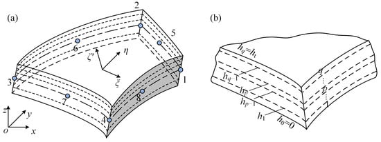
Figure 6.
Schematic of laminated shell elements: (a) shell element; (b) lamination diagram.
The relationship between coordinate system ξηζ′ and coordinate system ξηζ is denoted as
The mass matrix of the laminated shell element is written as
where ζp−1 and ζp are the material density of the p-th layer and q is the total number of layers. Np denotes the shape function matrix along the thickness direction ζ′. is written as .
The stiffness matrix of the laminated shell element can be written as
where B’p and Dp denote the strain and elastic matrices in the p-th layer of elements.
By assembling the stiffness and mass matrices of the element, those of the coated casing can be obtained. The equation of motion of the coated casing can be written as
where Mc, Cc, and Kc denote the mass, damping, and stiffness matrices of the coated casing. The expression for the damping matrix is denoted as
where and . fn1c (Hz) and fn2c (Hz) represent the first two NFs of the casings. ξ1 and ξ2 represent the damping ratios of the first and second modes, respectively.
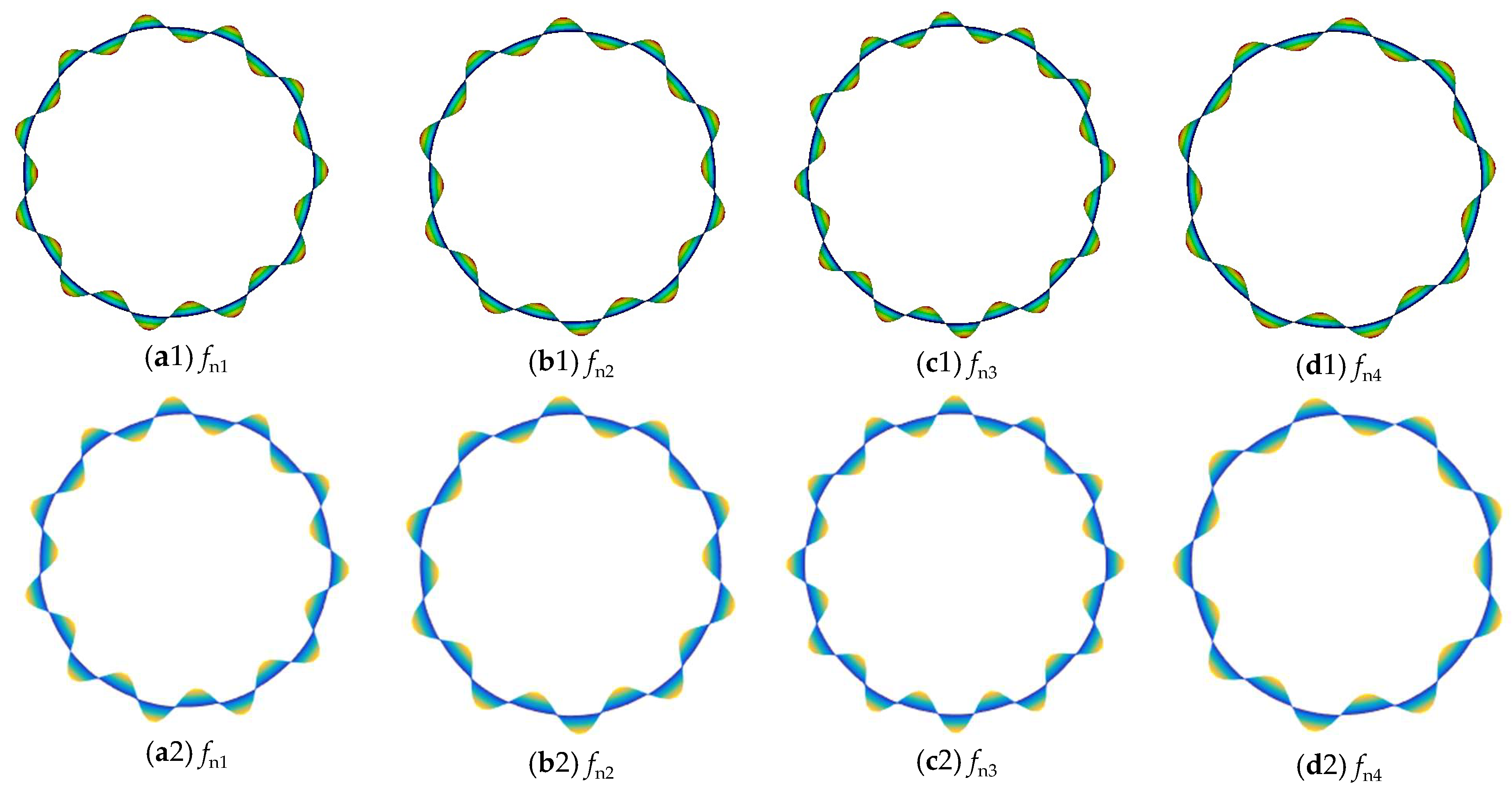
The proposed laminated shell model for the coated casing is validated by comparing the NFs with those obtained from the ANSYS software. The coating material is Metco 313 NS, and the material parameters are listed in Table 2. The first four NFs are presented in Table 3 and the mode shapes are presented in Figure 7. A comparison with the ANSYS results indicates that the errors in the first four NFs are all within 0.2%, and the mode shapes exhibit good consistency. This verifies the proposed dynamic model for the coated casing.
Table 2.
Parameters of the coated casing.
Table 3.
The first four NFs of the coated casing with fixed support.
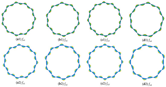
Figure 7.
Mode shapes of the first four modes of the coated casing (the first row comprises the mode shapes from the ANSYS software, and the second row comprises the mode shapes from the proposed model).
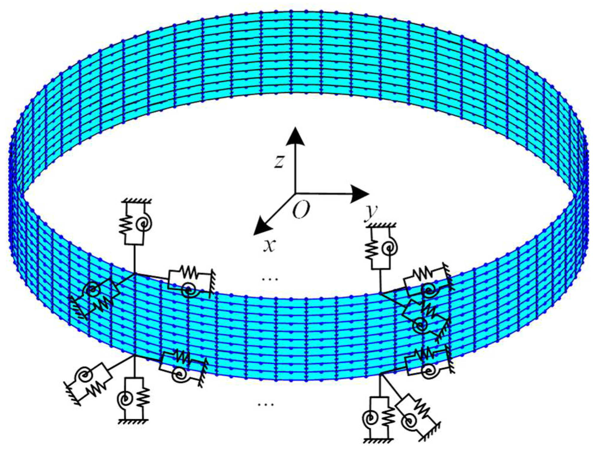
Three-dimensional linear spring elements are used at each node of both ends of the casing to simulate its elastic support. Spring elements are incorporated into the cylindrical coordinate system. This requires transformation to the cartesian coordinate system during stiffness matrix calculations. The stiffness values in each direction in the cylindrical coordinate system are N/m, N/m, N/m, N·m/rad, and N·m/rad. The FE model for the coated casing with elastic support is shown in Figure 8. The first six NFs of the casing with elastic support are shown in Table 4, and those of the proposed model show good consistency with the results from ANSYS. Thus, the proposed model for coated casings is verified considering elastic support. The error in the natural frequency of the casing is very small, so the source of this error may be numerical, including approximation and rounding errors.
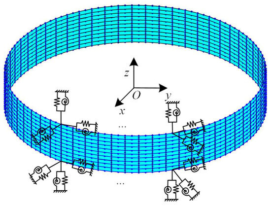
Figure 8.
FE model of the coated casing with elastic support.
Table 4.
The first six NFs of the coated casing with elastic support.
The proposed casing model consists of 3584 elements and 11,264 nodes (i.e., 67,584 degrees of freedom), which causes a low calculation speed. To enhance computational efficiency, the Craig–Bampton method is used to establish the reduced dynamic model. The reduced dynamic model for the casing is depicted as
The reduced casing has 320 degrees of freedom. Table 5 displays the first five NFs of the reduced dynamic model. The maximum error of the natural frequency is 0.307%. This meets the required accuracy standards and verifies the reduced dynamic model.
Table 5.
Comparison of NFs between the reduced model and unreduced model.
2.3. Dynamic Model of the Blade-Coated Casing System
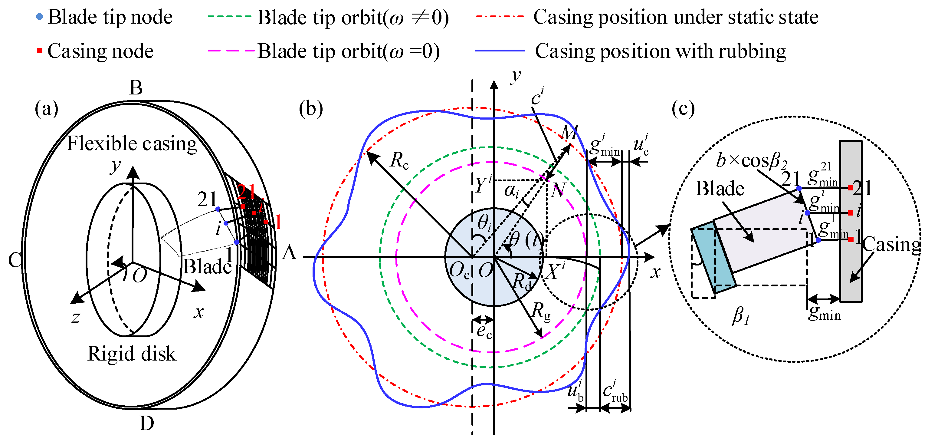
Considering static misalignment ec, the schematic of a rotating blade-flexible coated casing is shown in Figure 9, considering rubbing. Oc and O represent the centers of the casing and disk in a stationary state, respectively. Mesh refinement is implemented at locations susceptible to rubbing, as depicted in Figure 9a. In order to correspond to the node of the blade, the casing in the rubbing region is divided into 20 elements in the length direction. The non-rubbing regions on both sides of the casing are divided into two elements. Thus, the casing has a total of 24 elements in the length direction in Figure 9a. In Figure 9b, the casing position and blade tip orbit are displayed by the blue and pink lines when the rubbing fault occurs. By analyzing the gap between the blade tip and the casing, whether the rubbing fault occurs is judged and the normal rubbing force is calculated. The calculation process of is shown in Appendix B, and the expression of is shown in Equation (A29). Additionally, Figure 9c mainly shows the local contact between the blade and the casing.
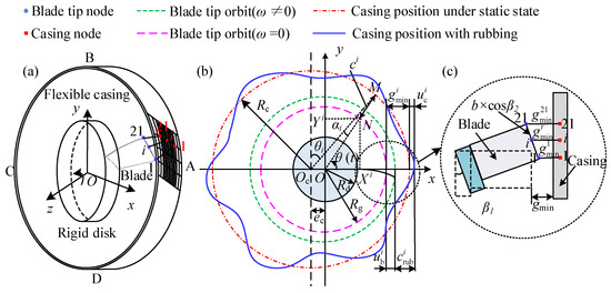
Figure 9.
Schematic of rubbing model [79]: (a) schematic of blade–casing rubbing; (b) blade–casing rubbing model; (c) partial enlarged drawing.
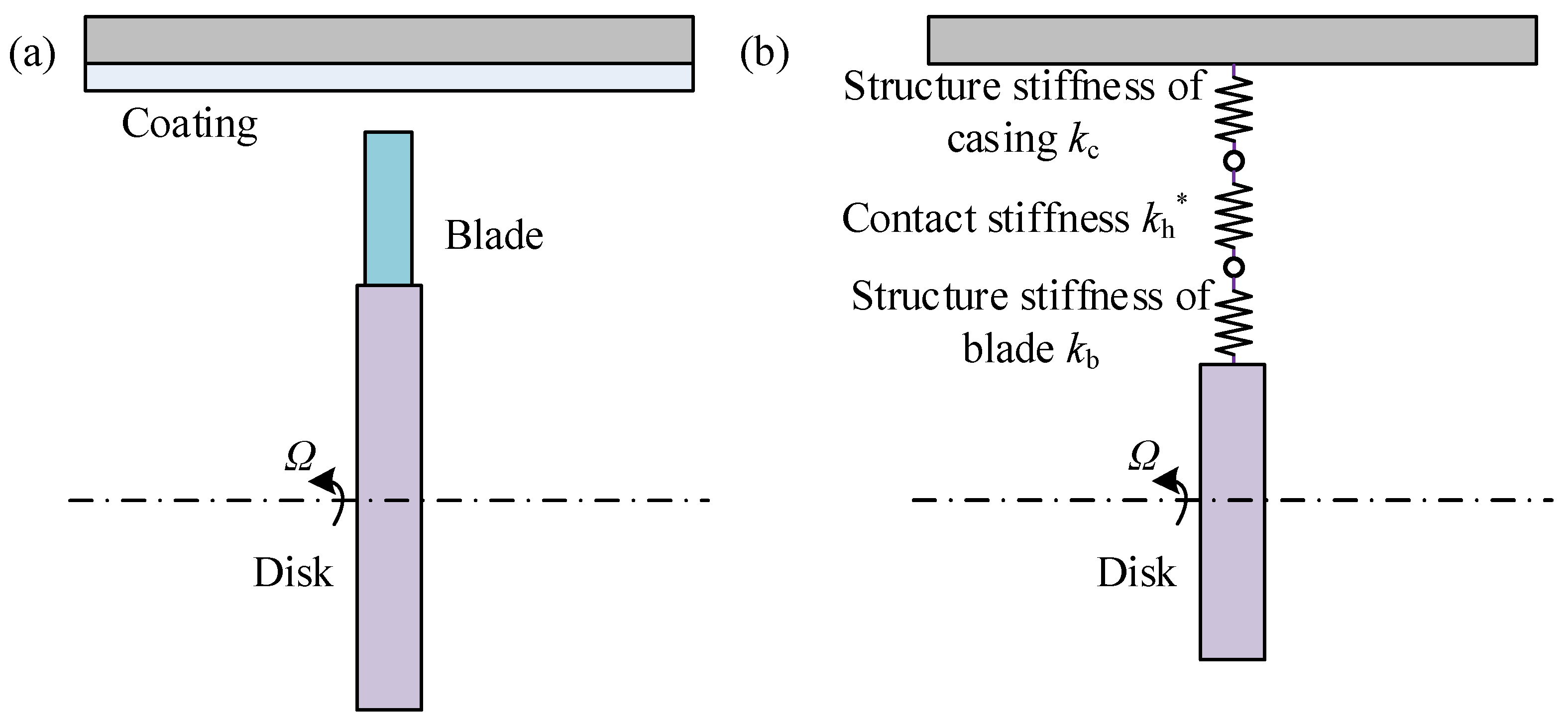
The rubbing model is shown in Figure 10. Figure 10a displays the blade-coated casing system. This rubbing model simultaneously considers the contact deformation between the blades and the casing, the structural deformation of each component, and the energy dissipation phenomenon caused by contact damping. The rubbing stiffness of the hysteresis contact-force model includes the structural stiffnesses kc and kb, as well as the local contact stiffness kh*. In other words, the rubbing stiffness is equal to the series stiffness of these three stiffness values, as shown in Figure 10b.
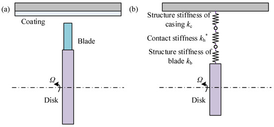
Figure 10.
Schematic of the hysteretic contact-force models: (a) blade-coated casing system; (b) equivalent contact diagram.
The detailed derivation of the rubbing force is shown in Appendix B.
During the operation of an aircraft engine, the blade is subjected to aerodynamic forces, and the overall aerodynamic load vector Qp is written as
where is the aerodynamic load of an element. The detailed expression can be found in Ref. [79].
Taking node pair 1 in Figure 9 as an example, the friction force is
where μ represents the frictional coefficient.
The rubbing forces and () are projected in the x and y directions. μ represents the friction coefficient. The resultant forces and are written as
where ω represents the rotating speed and ϕb represents the blade phase.
The expressions of Frb and Frc are
Thus, considering the rubbing forces, the dynamic model of the blade-coated casing is written as
where Frb, Frc, and Fc represent the rubbing force vectors of the blade and casing and the centrifugal force vector of the blade. The rubbing force is nonlinear, so once the system has a rubbing fault, the system will show obvious nonlinear characteristics.
3. Numerical Analysis
The casing is established using a laminated shell element with elastic support, while the blade is built as detailed in Section 2.2. The influence of the parameters related to the coating casing on the dynamic response of the system with rubbing is analyzed in this section.
3.1. Influence of the Casing Model
Guo et al. [41] analyzed the effects of casing models on rubbing, encompassing the lump-mass casing model and the cylindrical shell casing model. Inspired by Ref. [41], this subsection further compares the vibration responses of different casing models based on the hysteresis contact-force model, including the lump-mass casing model, cylindrical shell casing model, and laminated casing model. This comparison is conducted under the same geometric structure parameters and rubbing parameters. The simulation parameters of the blade are detailed in Table 6, and those of the casing are provided in Table 7. The dynamic responses are calculated by the Newmark-β method, and are detailed in Appendix C.
Table 6.
Simulation parameters of the blade.
Table 7.
Simulation parameters of the casing.
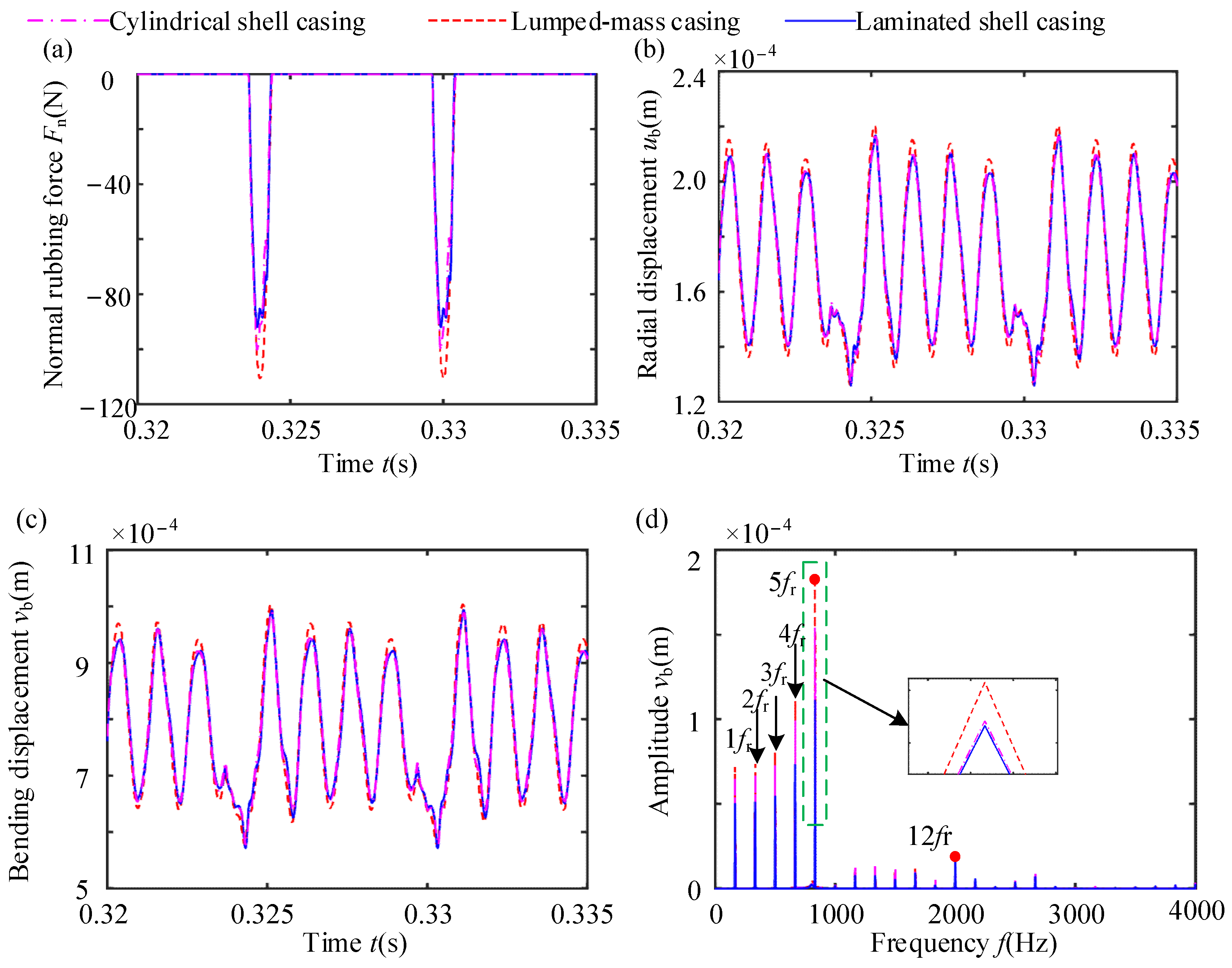
Figure 11 displays the time-domain waveform (TDW) of the rubbing forces and vibration response at the 21st node of the blade tips under three casing models. Notably, the different casing models exhibit a minimal difference in bending displacement and radial displacement. The frequency components remain consistent among these three models. Amplitude amplification is observed at frequency 5fr because frequency 5fr is close to the first natural frequency of the blade. Comparatively, the cylindrical shell casing model demonstrates a slight reduction in the maximum normal rubbing force, radial displacement, and bending displacement in contrast to the lumped-mass casing model. This phenomenon can be attributed to the localized deformation of the cylindrical shell casing model under the action of the normal rubbing force. This deformation increases the gap between the blade and the casing in subsequent load steps, ultimately reducing blade penetration and the severity level of rubbing.
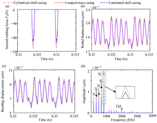
Figure 11.
NRFs and vibration responses of blades for various casing models: (a) NRF; (b) TDW of radial displacement; (c) TDW of bending displacement; (d) spectrum.
The natural characteristics and radial equivalent stiffness of the casing are directly influenced by changing the material parameters. The first NFs of the cylindrical shell casing and laminated shell casing are 906.12 Hz and 823.55 Hz, respectively. The equivalent radial stiffnesses are 1.396 × 10⁶ N/m and 1.336 × 10⁶ N/m, respectively. The equivalent radial stiffness of the laminated shell casing is greater than that of the cylindrical shell casing, but its maximum normal rubbing force, radial displacement, and bending displacement are slightly reduced compared to the cylindrical shell casing model (see Figure 11a), indicating that having a coating on the surface of the casing can reduce the severity level of blade–casing rubbing.
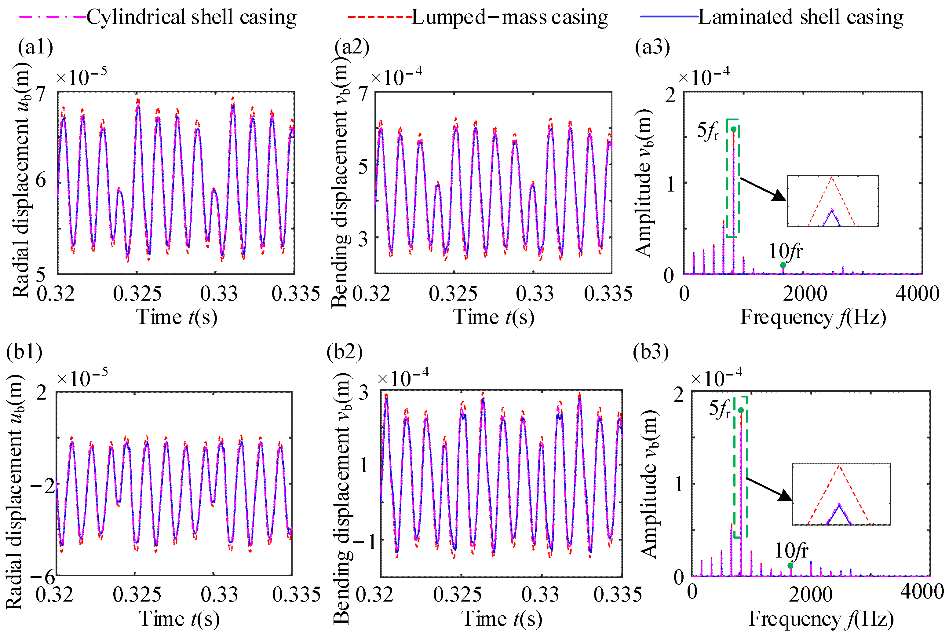
The vibration responses of the blade at the 11th and 1st nodes of the blade tip are shown in Figure 12. When comparing Figure 11 and Figure 12, a notable difference in the radial and bending displacements can be found among the blade tips. Specifically, the radial and bending displacements of the blade tip nodes exhibit a gradual decrease with the change in the position at the blade tip. This is because the thickness of the blade is non-uniform, and the elongation of each node at the blade tip is different under the action of the centrifugal force. Near the 21st node, contact between the blade tip and the casing appears, causing a reduction in the radial and bending displacements. Of course, an obvious conclusion is that changes in the casing model will not cause changes in frequency components, only in amplitude.

Figure 12.
Vibration responses of different nodes at blade tips: (a1,b1) radial displacement; (a2,b2) bending displacement; (c1,c2) spectrum. The first row shows the response at the 11th node of the blade tip. The first row shows the response at the 1st node of the blade tip.
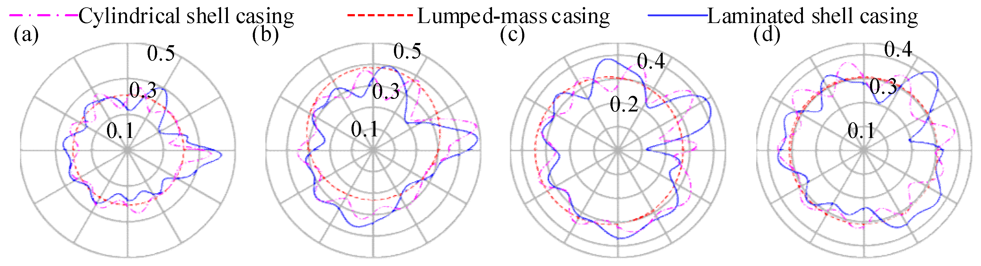
The blade passes the coated casing at four positions: points A (0), B (π/2), C (π), and D (3π/2), the deformation diagram of the casing is shown in Figure 13. The definition of the points can be found in Figure 9a. At position A, blade–casing rubbing can obviously be found. When rubbing occurs, the deformation of laminated shell models at point A is greater than that of the cylindrical shell models, and the deformation of the two models at that point is significantly greater than that at the other points. However, for the lumped-mass casing, the overall casing is translated to the right due to rubbing forces. Additionally, obvious NDVCs can be observed in the cylindrical shell model and the laminated shell casing model. However, the induced NDVCs are also different among these two flexible casing models.
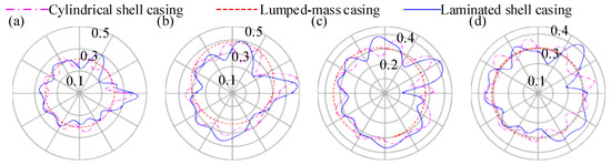
Figure 13.
Deformation diagrams of the casing at different moments (unit: m): (a) t=0.324 s, corresponding to point A; (b) t=0.3255 s, corresponding to point B; (c) t=0.3247 s, corresponding to point C; (d) t = 0.3285 s, corresponding to point D.
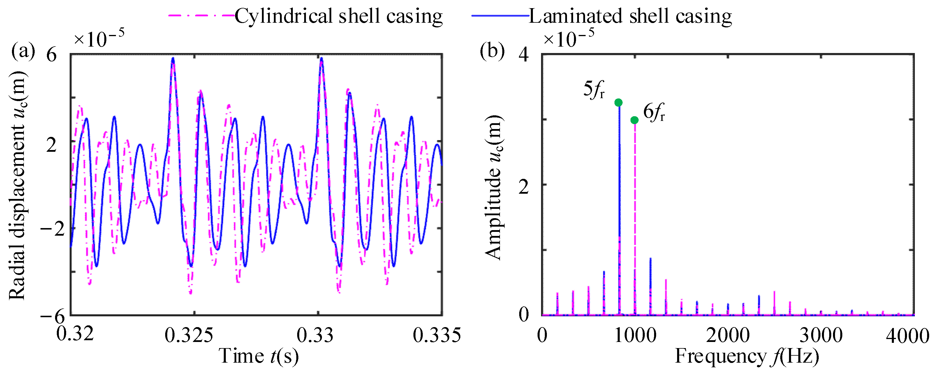
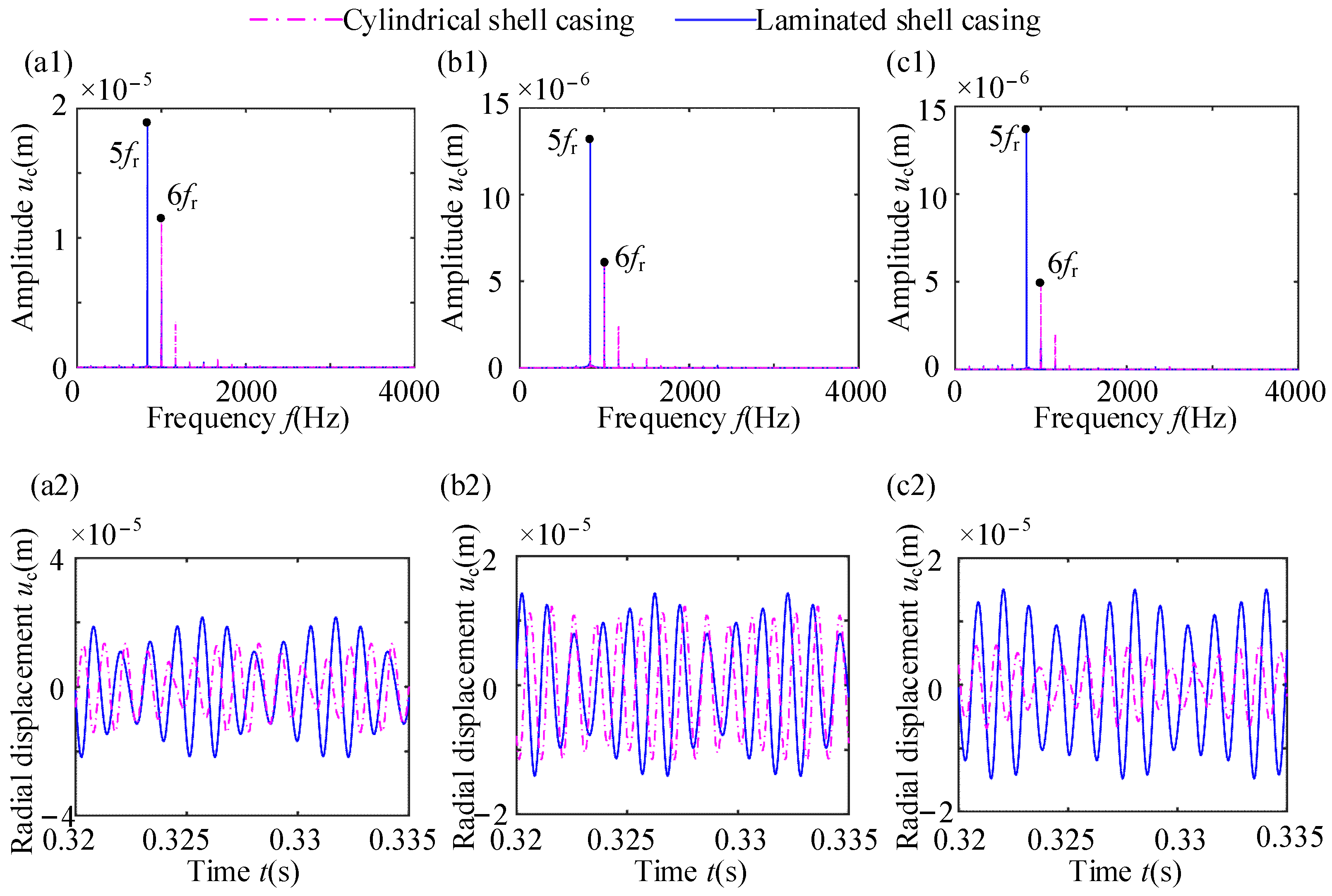
The time-domain waveforms and the spectra of radial vibration at points A, B, C, and D are shown in Figure 14, Figure 15 and Figure 16. In these figures, the radial displacement of the rigid casing is much smaller than that of the cylindrical shell casing and laminated shell casing. The difference in radial displacement between the cylindrical shell casing and the laminated shell casing at the rubbing point is not significant, but at the non-rubbing position, the laminated shell casing has a larger vibration displacement compared to the cylindrical shell casing. Additionally, there is a significant difference in the frequency components between the two flexible casing models. The cylindrical shell casing exhibits amplitude amplification at frequency 6fr, while the laminated shell casing exhibits amplitude amplification at frequency 5fr, and exhibits dense frequency characteristics at rubbing point A. At non-rubbing points (points B, C, and D), the cylindrical shell casing and the laminated shell casing also exhibit amplitude amplification at 6fr and 5fr, respectively. The main reason for the above differences is the difference in natural characteristics between the cylindrical shell casing and the laminated shell casing.
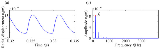
Figure 14.
Vibration response of rigid casing: (a) time-domain waveform; (b) spectrum.

Figure 15.
Vibration response of rubbing point A with the flexible casing: (a) time-domain waveform; (b) spectrum.
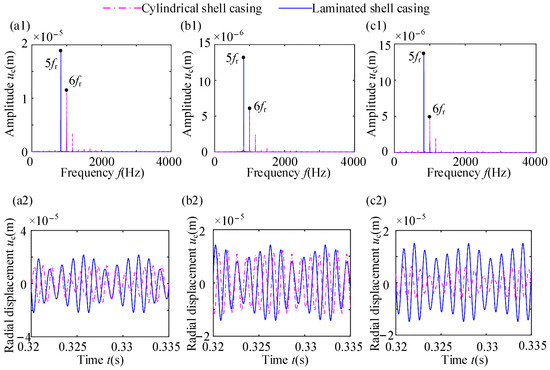
Figure 16.
Vibration responses of rubbing points B, C, and D with flexible casing: (a1,a2) point B; (b1,b2) point C; (c1,c2) point D.
3.2. Influence of Coating Thickness
Changes in coating thickness directly affect the natural characteristics and radial stiffness of a casing. Therefore, the influences of coating thickness are investigated.
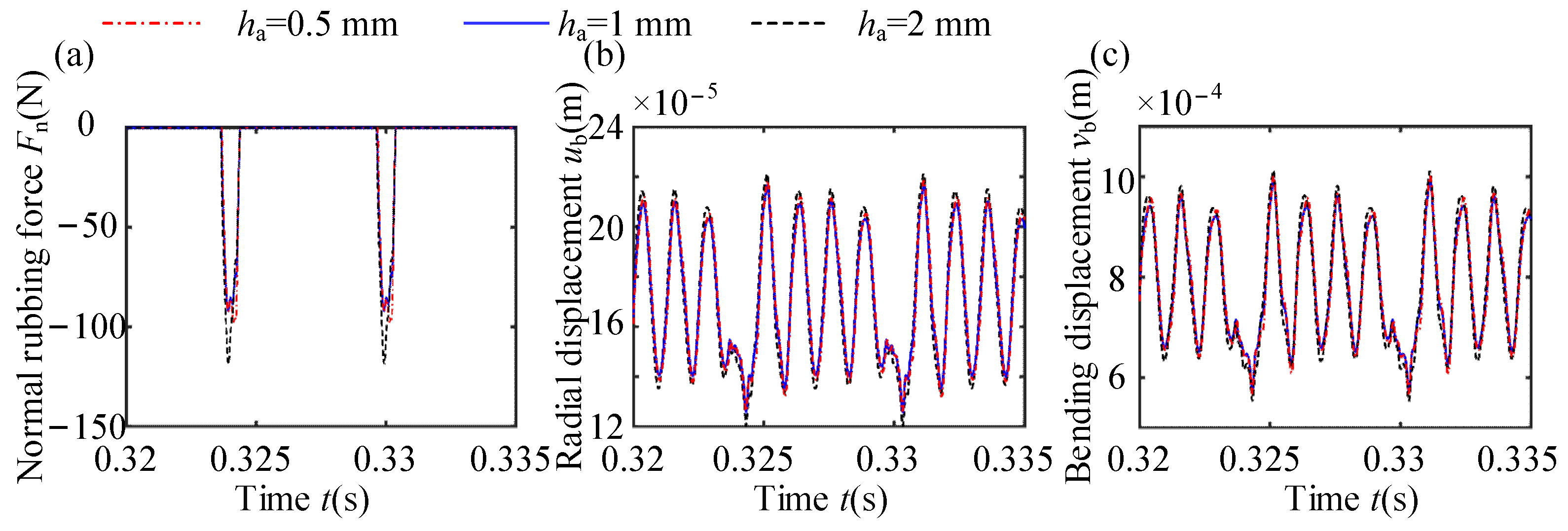
The NRF and dynamic response at the 21st node are shown in Figure 17. The equivalent radial stiffnesses of casings with coating thicknesses of , , and are 1.357 × 10⁶ N/m, 1.396 × 10⁶ N/m, and 1.54 × 10⁶ N/m, respectively. Correspondingly, the first NFs are 860.68 Hz, 823.55 Hz, and 768.99 Hz, respectively. Notably, the equivalent radial stiffness increases with the increase in coating thickness, which causes rubbing force to increase. However, in Figure 18, the rubbing force at a 0.5 mm thickness is greater than that at a 1 mm thickness. The main reason is that the radial displacement of the 1 mm coating thickness at the rubbing point is greater than that of the 0.5 mm coating thickness during the initial rubbing time period from 0.3238 s to 0.324 s, resulting in a smaller penetration between the blade and casing, and ultimately a smaller rubbing force. The coating thickness has a slight effect on the response amplitude of the blade.
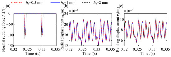
Figure 17.
Normal rubbing forces and vibration responses at various coating thicknesses: (a) NRF; (b) TDW of radial displacement; (c) TDW of bending displacement.
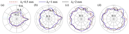
Figure 18.
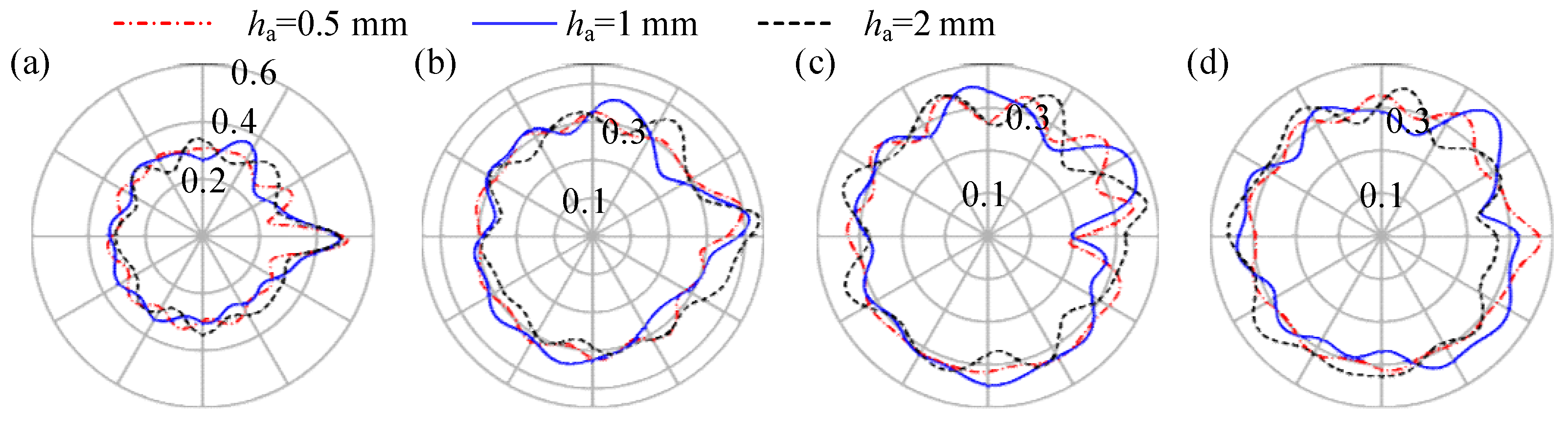
Deformation diagrams of the casing at different moments (unit: m): (a) ; (b) ; (c) ; (d) .
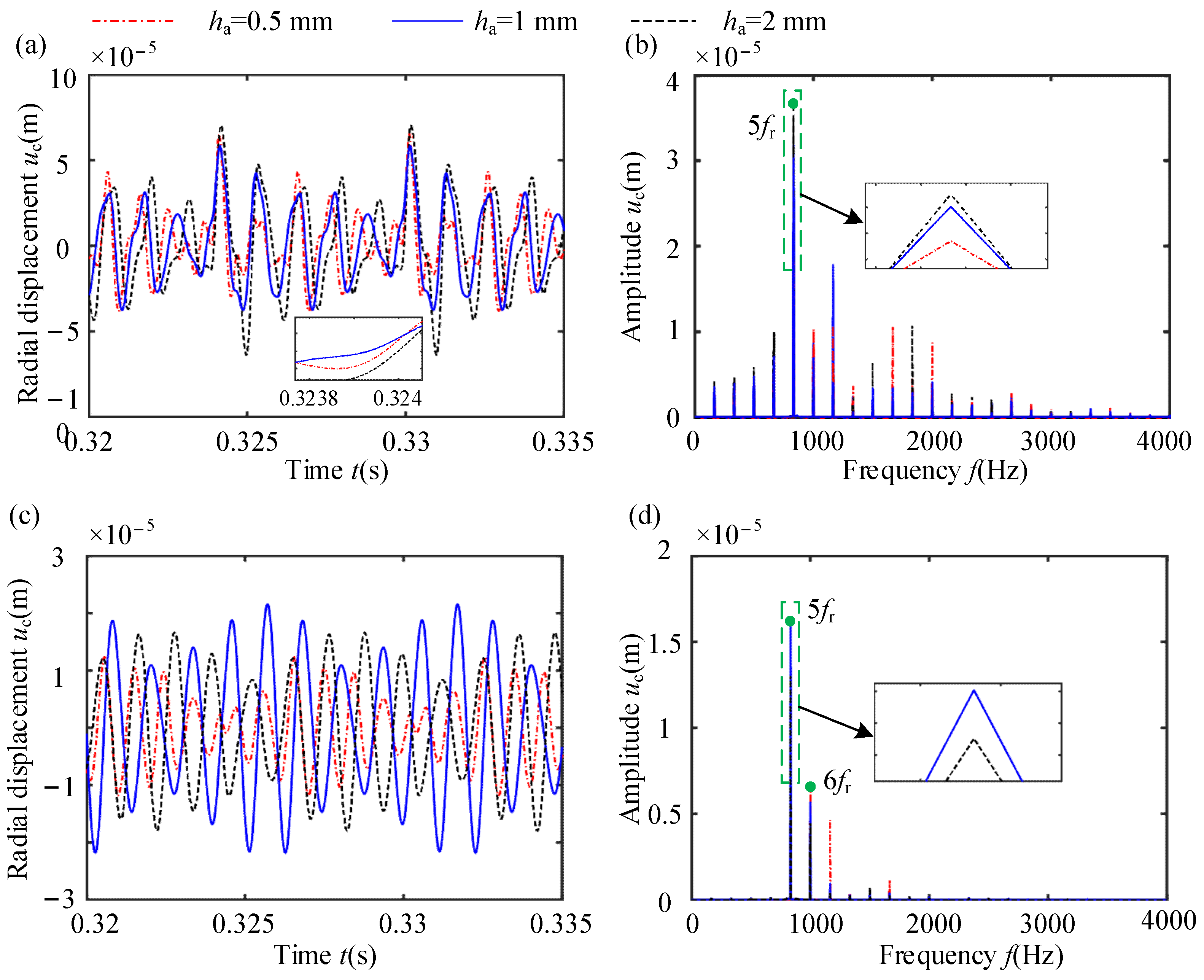
From Figure 18 and Figure 19, it is evident that the NDVCs induced by rubbing under different coating thicknesses are different. At rubbing point A, the radial displacement and frequency components of the casing under the three coating thicknesses show minimal differences, and an amplitude amplification phenomenon is observed at frequency 5fr. Conversely, at non-rubbing point B, there is a notable difference in the radial displacement and frequency components of the casing. Specifically, when the coating thicknesses are 1 mm and 2 mm, the amplitude amplification phenomenon occurs at frequency 5fr. In contrast, when the coating thickness is 0.5 mm, the amplitude amplification phenomenon appears at frequency 6fr in Figure 19d.
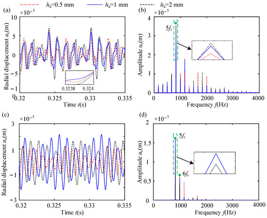
Figure 19.
Dynamic responses of casings at various coating thicknesses: (a) TDW of displacement at point A; (b) displacement spectrum at point A; (c) TDW of displacement at point B; (d) displacement spectrum at point B.
3.3. Influence of Coating Material
A comparative analysis of NRF and vibration response under three coating materials (Metco 308 NS, Metco 601 NS, and Metco 313 NS) is conducted. The corresponding material parameters are detailed in Table 8. Variations in coating materials lead to alterations in the NF and equivalent radial stiffness of the casing, and the results are shown in Table 8.
Table 8.
Material parameters, NF, and equivalent radial stiffness of coatings.
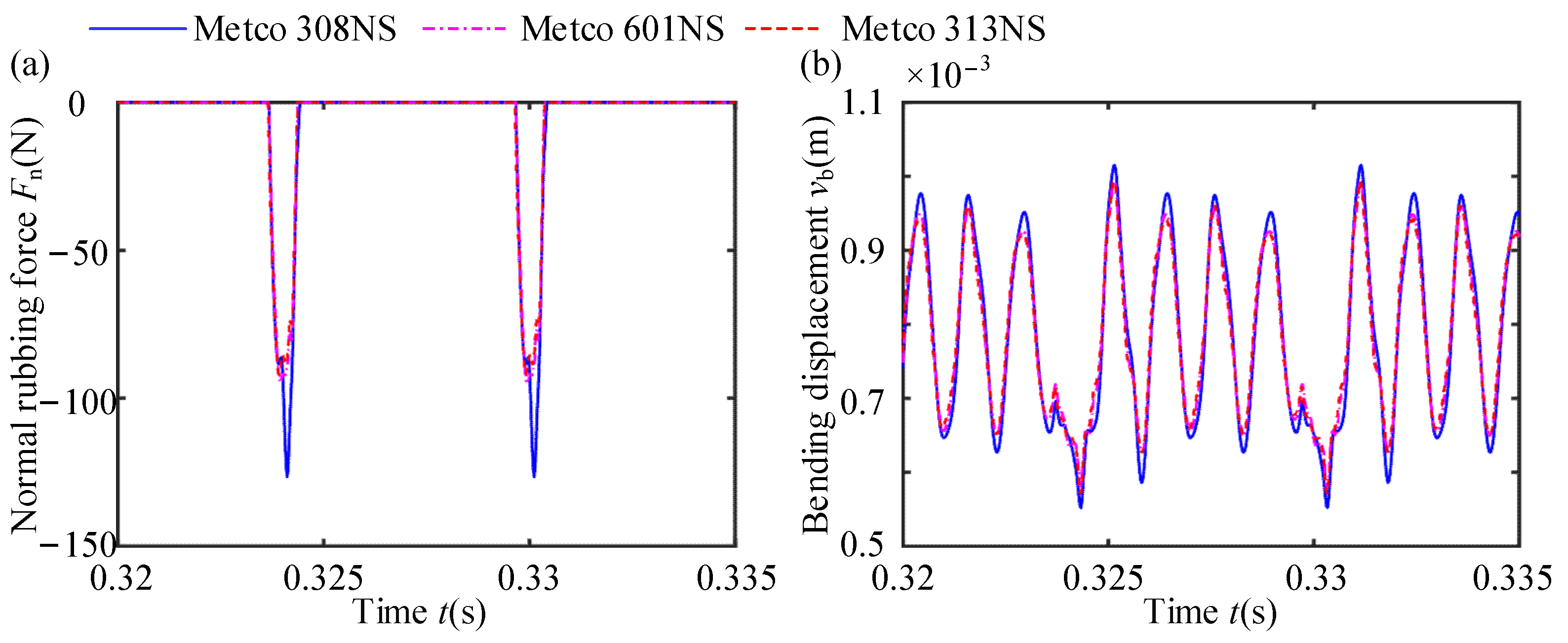
Figure 20, Figure 21 and Figure 22 display the TDW of NRF, the vibration response of the blade, casing deformation, and the vibration response of the casing at points A and B under different coating materials. Observations from these figures reveal that, when the coating material is Metco 308 NS, the NRF is the largest, and the NDVCs induced by rubbing are more pronounced. Conversely, the normal rubbing force, vibration response of the blade, and vibration response of the casing at points A and B are roughly the same when the coating materials are Metco 601 NS and Metco 313 NS. However, it is noteworthy that Metco 601 NS is primarily suitable for low-pressure compressors at low-temperature conditions. Therefore, for the purposes of this simulation and analysis, Metco 313 NS is chosen as the coating material to study in this paper. The vibration response induced by rubbing can serve as a crucial criterion for the selection of coating materials in the design process of blade-coated casing systems.
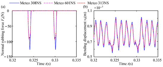
Figure 20.
Normal rubbing forces and dynamic responses of blades with various coating materials: (a) normal rubbing force; (b) bending displacement of the 21st node of the blade tip.
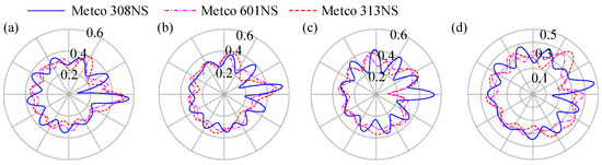
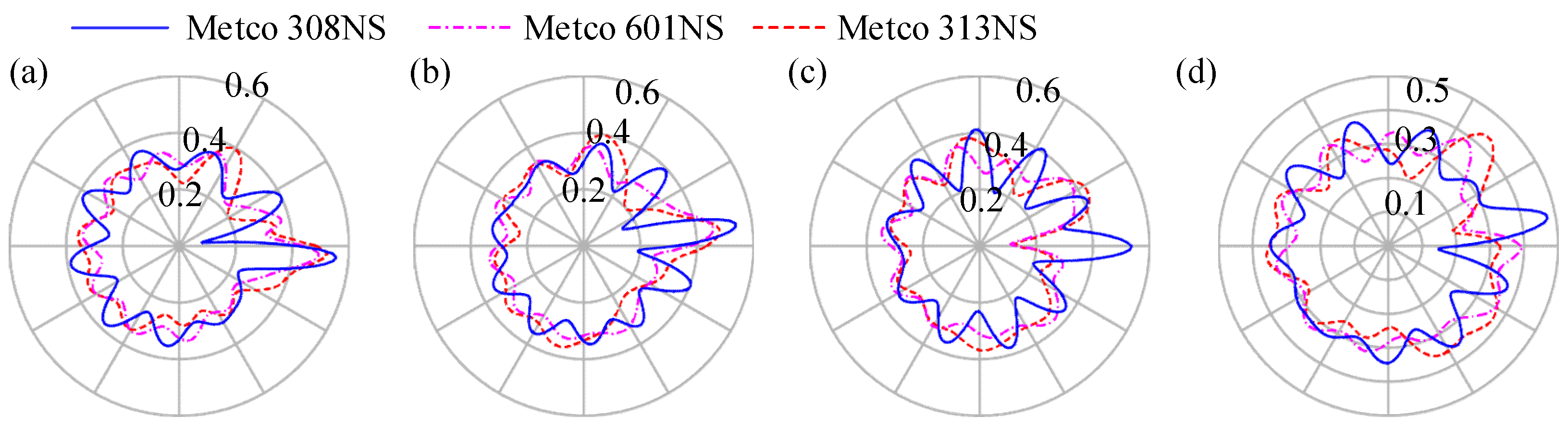
Figure 21.
Deformation diagrams of the casing at different moments: (a) , (b) , (c) , (d) .
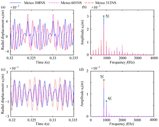
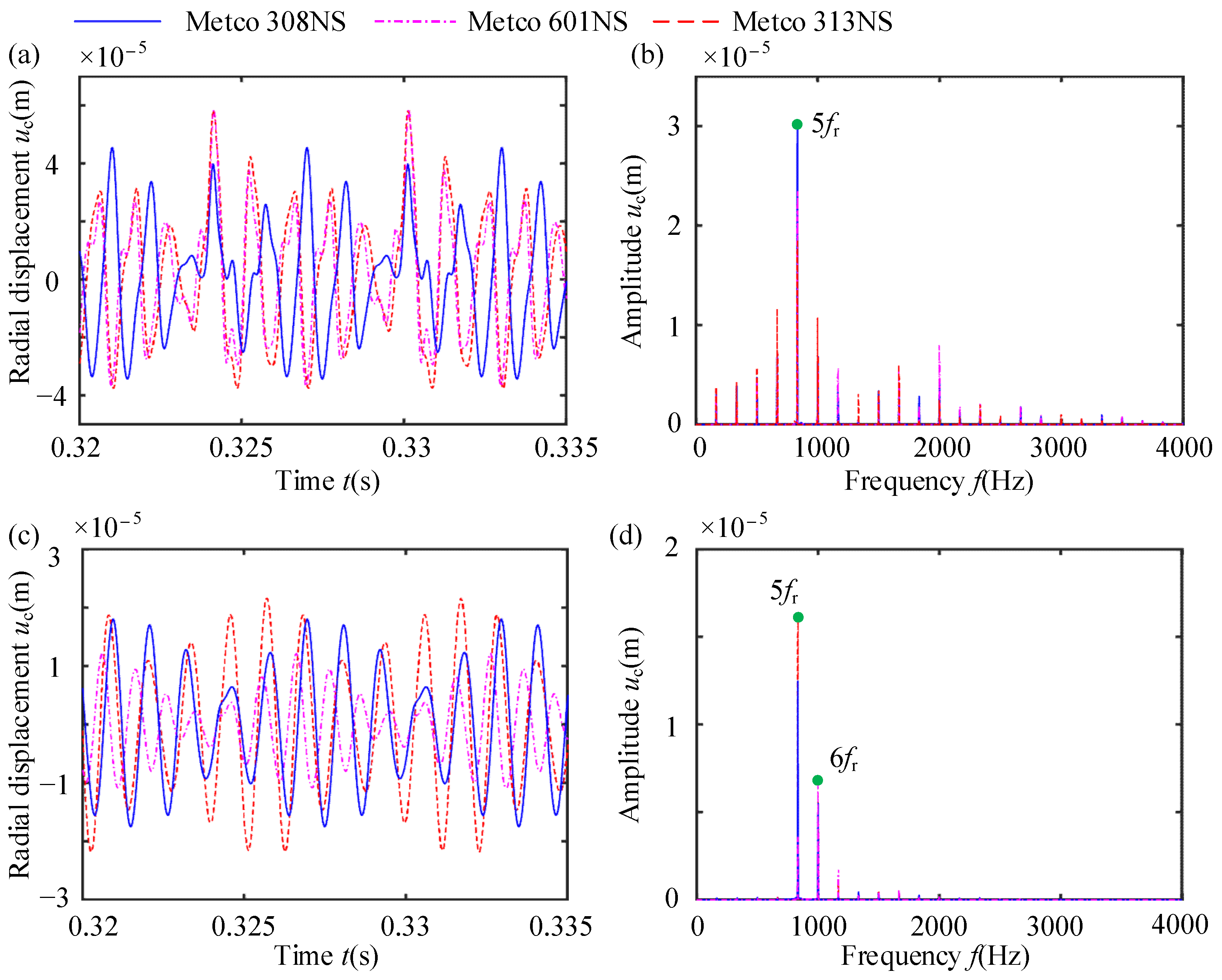
Figure 22.
Dynamic responses of casings with various coating materials: (a) TDW of displacement at point A; (b) displacement spectrum at point A; (c) TDW of displacement at point B; (d) displacement spectrum at point B.
Figure 21 and Figure 22 reveal variations in radial displacements, frequency components, and induced NDVCs under different coating materials. At rubbing point A, an amplitude amplification phenomenon is consistently observed at frequency 5fr for all three materials. However, at non-rubbing point B, the amplitude amplification phenomenon occurs at frequency 5fr for both Metco 308 NS and Metco 313 NS materials, while for the Metco 601 NS material casing, the amplitude amplification phenomenon appears at frequency 6fr. These differences highlight the sensitivity of the vibration response of casings to the choice of coating materials, emphasizing the importance of this factor in material selection for good performance when rubbing occurs in a blade-coated casing system.
3.4. Influence of the Support Stiffness of the Coated Casing
The elastic support stiffness of casings can influence natural characteristics and the equivalent radial stiffness of the casing. Therefore, this section discusses the effects of the radial, tangential, and axial elastic support stiffnesses of casings on the equivalent radial stiffness of the casing and the vibration response of the system. Simulation parameters are listed in Table 9.
Table 9.
Simulation parameters.
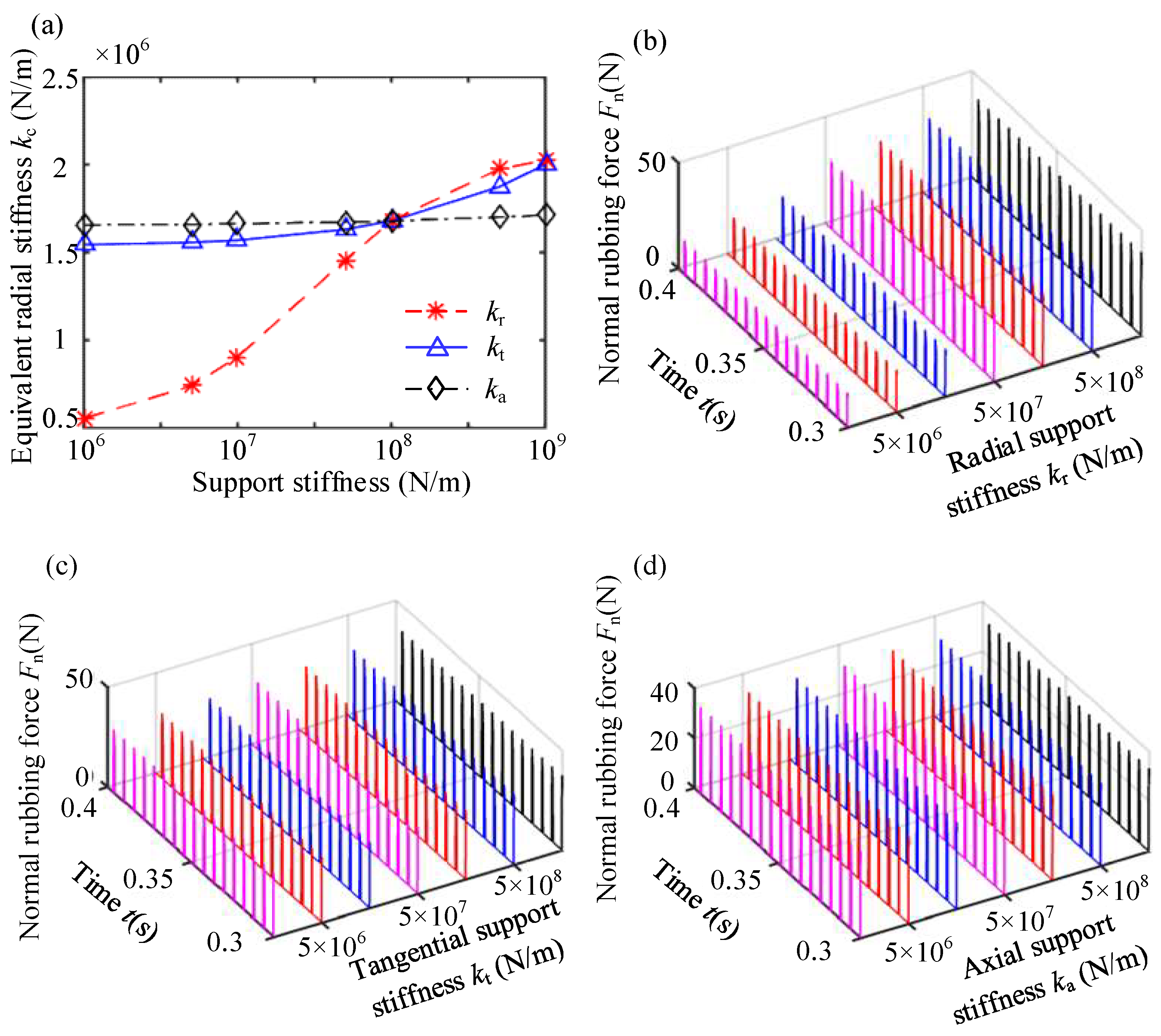
Figure 23, Figure 24 and Figure 25 show the equivalent radial stiffnesses and rubbing forces of the casings under different elastic support stiffnesses. The vibration response of the 21st node of the blade tip and the vibration response at point A of the casing are analyzed. Some conclusions are listed as follows:

Figure 23.
Equivalent stiffness of rubbing and NRF with different spring stiffnesses: (a) equivalent radial stiffness of the coated casing; (b) influence of radial support stiffness; (c) influence of tangential support stiffness; (d) influence of axial support stiffness.

Figure 24.
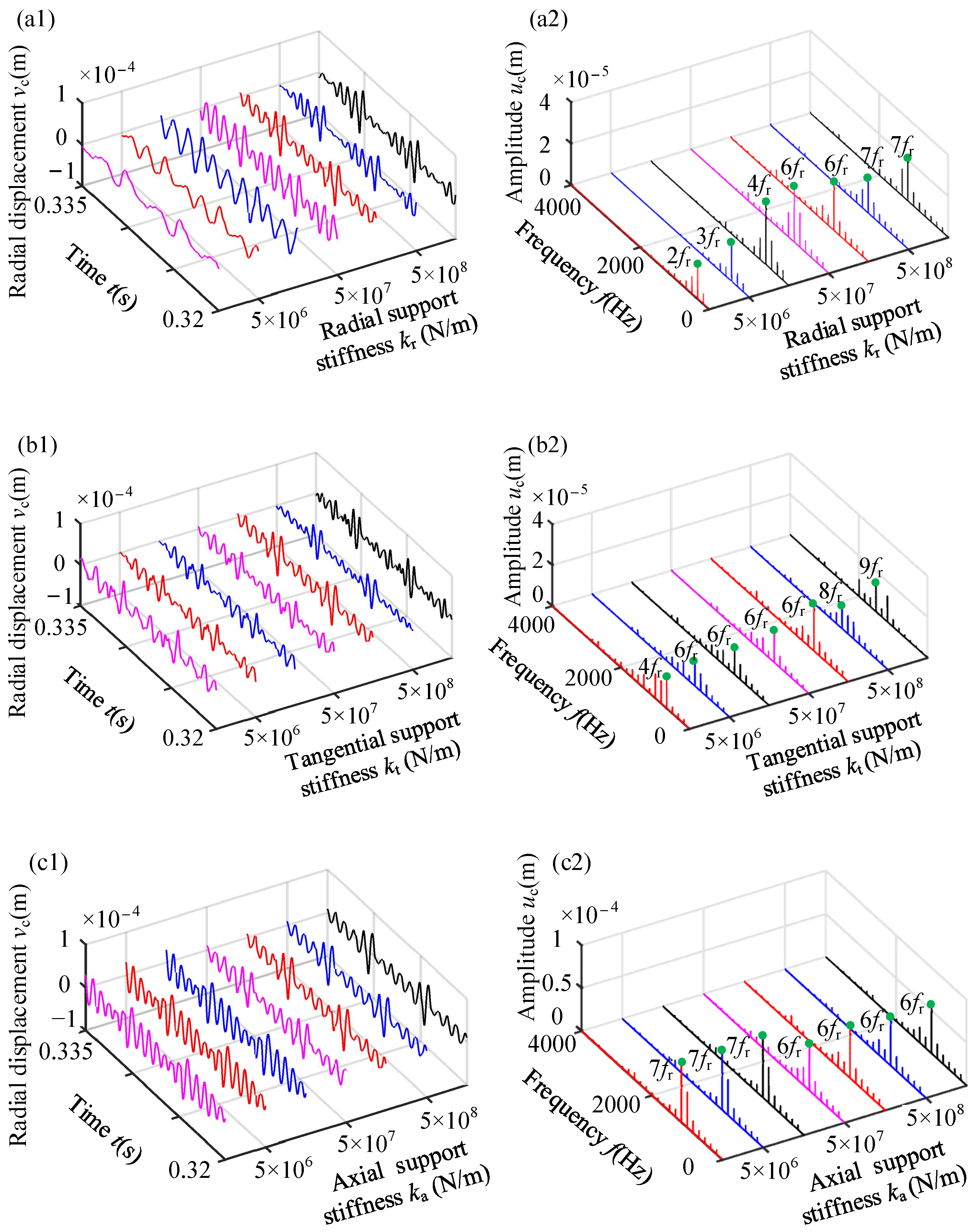
Vibration responses of the blade with different radial spring stiffnesses: (a) TDW of bending displacement; (b) spectrum cascades of bending displacement.
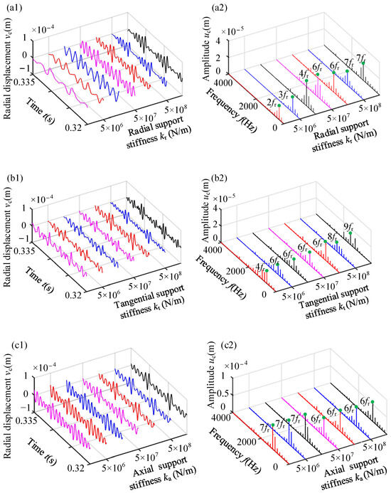
Figure 25.
Dynamic responses of point A with various spring stiffnesses: (a1,a2) influence of radial support stiffness; (b1,b2) influence of tangential support stiffness; (c1,c2) influence of axial support stiffness. The left side of the figure shows the TDW of the displacement and the right shows the spectrum.
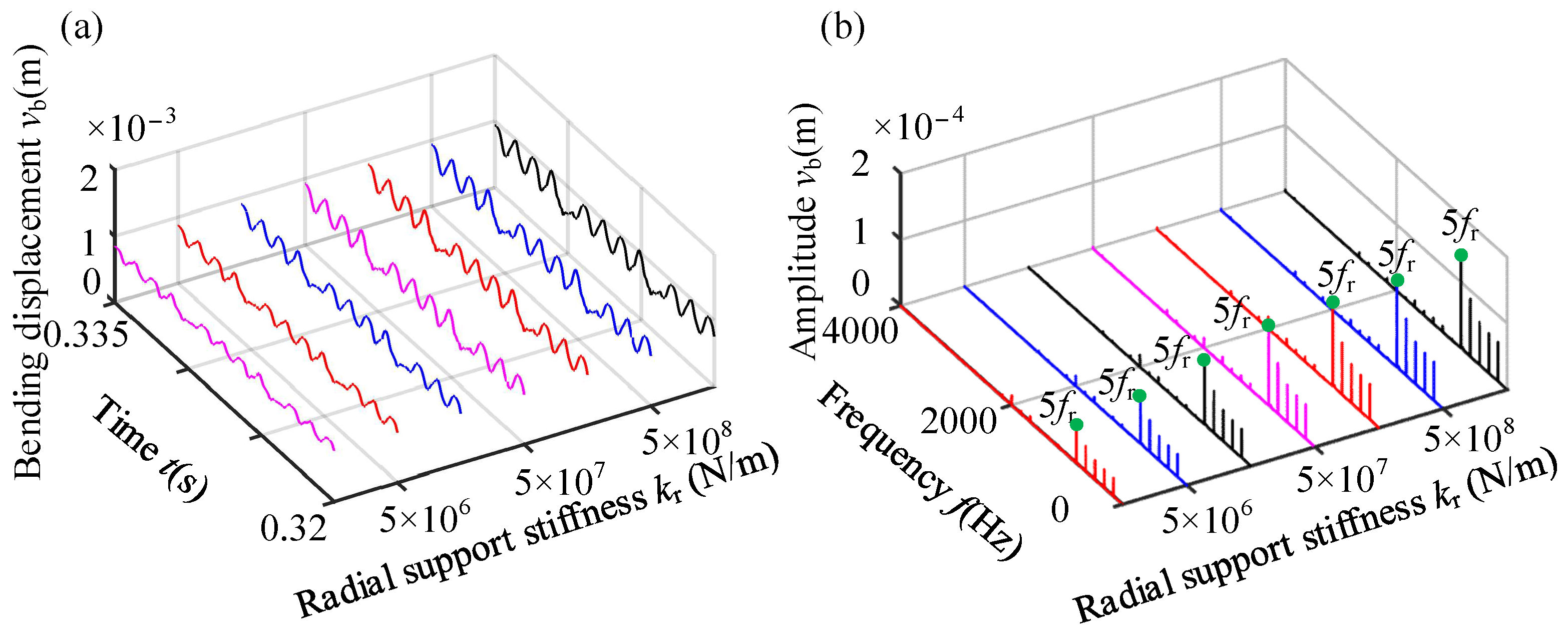
(1) Equivalent radial stiffness exhibits an increase with the rise in elastic support stiffness. Specifically, the equivalent radial stiffness and maximum rubbing force are primarily influenced by the radial and tangential elastic support stiffnesses, and the axial elastic support stiffness has a minimal effect on the equivalent radial stiffness and maximum normal rubbing force. The equivalent radial stiffness undergoes significant variations when the radial elastic support stiffness ranges from 1 × 10⁶ N/m to 1 × 10⁸ N/m and the tangential elastic support stiffness ranges from 1 × 10⁸ N/m to 1 × 10⁹ N/m. Overall, the radial elastic support stiffness has the most obvious influence on the equivalent radial stiffness of the coated casing.
(2) As the radial elastic stiffness of the casing increases, there is an obvious increase in the amplitudes of rubbing force and vibration displacement, while the frequency component remains unchanged. The support stiffness in three directions exerts a notable influence on the radial vibration response at point A of the casing. Specifically, with an increase in radial and tangential stiffness, the frequency corresponding to the amplitude amplification phenomenon also increases. This is attributed to the difference in the natural frequency of the casing induced by changes in the support stiffness of the coated casing.
3.5. Influence of the Length of the Coated Casing
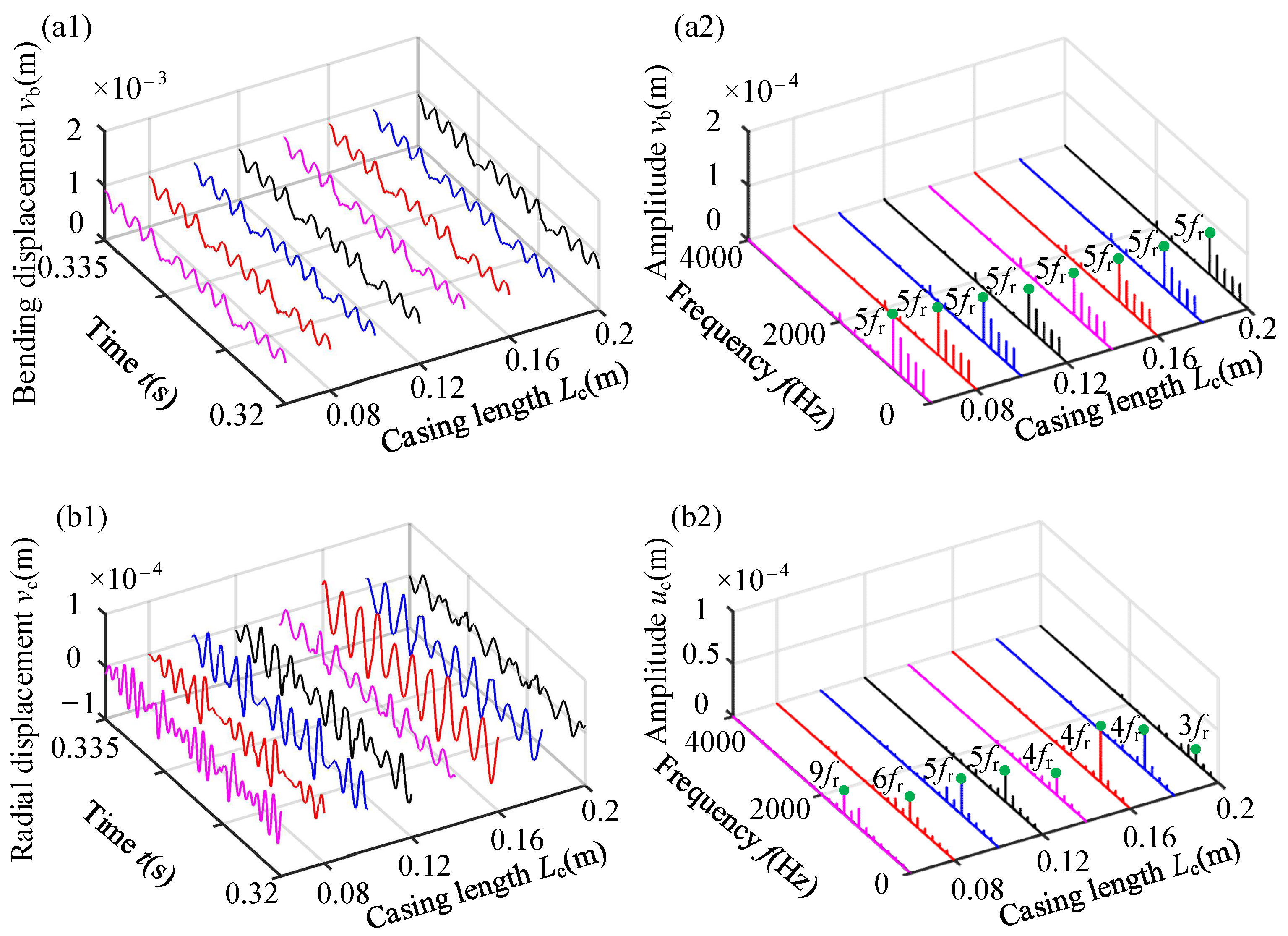
The length of the casing directly affects the natural frequency and equivalent radial stiffness of the coated casing. Therefore, this section analyzes the effect of casing length on vibration response. The vibration response of the 21st node of the blade tip and the vibration response at point A of the casing are shown in Figure 26. The first natural frequency, equivalent radial stiffness, and maximum normal rubbing force of the 21st node under different casing lengths are listed in Table 10.
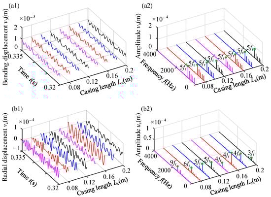
Figure 26.
Vibration responses of blade–casing rubbing with different casing lengths: (a1,a2) 21st node of the blade tip; (b1,b2) point A of the casing.
Table 10.
The first NF and equivalent radial stiffness of the casing at different lengths.
As shown in Figure 26, a change in the length of the casing only slightly affects the amplitude of the bending vibration of the blade and does not affect the frequency component. It can be also observed that the length of the casing has a significant influence on the radial displacement at point A of the casing. As the length of the casing increases, the amplitude amplification gradually decreases from frequency 9fr to frequency 3fr, which is caused by the difference in the natural frequency of the casing.
From Table 10, as the length of the casing increases, both the first natural frequency and equivalent radial stiffness of the casing decrease. However, the maximum normal rubbing force does not decrease with the reduction in the radial stiffness of the casing. The primary reason lies in the varying deformation of the casing with different lengths, leading to different penetrations between the blade and casing. Consequently, the rubbing force does not decrease proportionally with the decline in the radial stiffness of the casing. As depicted in Figure 26, changes in the length of the casing only slightly affect the amplitude of the bending vibration of the blade and have no obvious effect on the frequency components. Simultaneously, the length of the casing significantly influences the radial displacement at point A of the casing. With the increase in casing length, the amplitude amplification gradually decreases from frequency 9fr to frequency 3fr.
4. Conclusions
To investigate blade-coated casing rubbing, an FE model of a laminated shell casing is established using eight-node shell elements. The accuracy of the model is validated by comparing its natural characteristics with the results obtained from ANSYS software. Additionally, an actual compressor blade with varying sections and a twisted shape is also established using the shell element. Subsequently, based on hysteretic contact force, a dynamic model with rubbing is established to investigate rubbing-induced vibration characteristics. Some key conclusions can be summarized as follows:
(1) The vibration responses of the blade–casing system with rubbing are analyzed among three casing models: the lumped-mass model, the cylindrical shell model, and the laminated shell model. The study reveals that the vibration response amplitude of the laminated-blade shell casing with rubbing is the smallest. This indicates that the coating can reduce the severity level of rubbing. Additionally, the frequency corresponding to the amplitude amplification phenomenon of the cylindrical shell model and the laminated shell model at the rubbing and non-rubbing points are different due to variations in natural characteristics.
(2) Furthermore, the material and thickness of the coating can change the NDVCs induced by rubbing. The frequency corresponding to amplitude amplification is also influenced by the casing support stiffness and casing length, as these parameters change the natural characteristics of the casing.
The primary contribution of this article lies in the establishment of a dynamic model for an actual blade-coated casing, taking into account rubbing faults. The study emphasizes understanding the effects of coating and casing on dynamic responses in the presence of rubbing, with a specific focus on analyzing casing vibration. It is important to note that this article does not address coating wear, which stands out as a potential focus for future work. The study of these dynamics considering wear would provide a more comprehensive understanding of dynamic behavior under operational conditions.
Author Contributions
Conceptualization, Y.Z. and S.Y.; methodology, L.Q.; software, H.G.; validation, L.Q.; investigation, X.T.; resources, Y.Z.; data curation, X.D.; writing—original draft preparation, H.G.; writing—review and editing, H.M. and Q.M.; visualization, L.Q.; supervision, H.M.; project administration, Y.Z.; funding acquisition, H.M. All authors have read and agreed to the published version of the manuscript.
Funding
This work was financially supported by the National Science and Technology Major Project (J2022-IV-0005-0022) and Aero Science Foundation of China (20230015050001).
Data Availability Statement
Data will be made available on reasonable request.
Conflicts of Interest
Authors Y.Z., S.Y. and X.T. were employed by Shengu Group Co., Ltd. Author L.Q. was employed by Sunny Optical Technology (Group) Co. Ltd. The remaining authors declare that the research was conducted in the absence of any commercial or financial relationships that could be construed as a potential conflict of interest.
Abbreviation
All symbols are listed as follows:
| Nomenclature | |
| b | Blade width |
| B′p | Strain matrix in the local coordinate system ξηζ’ of the shell |
| ci | Initial clearance between the blades and the casing |
| Dynamic clearance between blade tip node i and casing | |
| Clearance between blade tip node i and casing at the jth and j-1th load steps | |
| ce | Collision recovery coefficient |
| C | Damping matrix of the blade |
| Cc | Damping matrix of the coated casing |
| Damping matrix of the reduced coated casing | |
| Dp | Elastic matrix in the local coordinate system ξηζ’ of the shell |
| ec | Misalignment distance |
| Ea | Elastic modulus of the coating |
| Eb | Elastic modulus of the blade |
| Ec | Elastic modulus of the casing |
| fn1c, fn2c | First and second NFs of the casing |
| Fe1 | Aerodynamic amplitude |
| Normal rubbing force of the ith node at the blade tip | |
| External force vector of the reduced coated casing | |
| Frb, Frc | Rubbing force vector of the blade and casing |
| Minimum clearance between the first node of the blade tip and the casing | |
| gmin | Minimum clearance between the blade tip and the casing at β1 = 0° |
| G | Coriolis force matrix of the blade |
| ht | Total thickness of the laminated shell |
| hp-1, hp | Upper and lower boundaries of the p-th layer |
| ha | Thickness of the coating |
| hc | Thickness of the casing |
| kh | Hertz contact stiffness |
| kh* | Contact stiffness between the blade and casing |
| kb, kc | Structure stiffness of the blade and casing |
| ks | Structural stiffness of the blade in series with the casing |
| kx, ky, kz, kθx, kθy, kθz | Root constraint stiffness of the blade |
| kr, kt, ka, kθr, kθt | Root constraint stiffness of the casing |
| Equivalent rubbing stiffness | |
| Ke, Kce, Kco, Ks | Structure stiffness, centrifugal stiffening, elastic support stiffness, and spin softening matrixes of the blade |
| Ke | Stiffness matrix of the shell element |
| Kc | Stiffness matrix of the coated casing |
| Stiffness matrix of the reduced coated casing | |
| Lc | Length of casing |
| mc | Mass of the casing |
| M | Mass matrix of the blade |
| Me | Mass matrix of the shell element |
| Mc | Mass matrix of the coated casing |
| Mass matrix of the reduced coated casing | |
| q | Total number of floors |
| Displacement, velocity, and acceleration vectors of the reduced casing | |
| Qp | Aerodynamic load |
| Rd | Radius of the disk |
| Rc | Inner diameter of casing |
| Rg | Orbit radius of the blade tip in a stationary state |
| Zi, Xi | Initial coordinate of the blade tip in the x and z directions |
| , | Radial displacement of the i-th node of the casing and the i-th node of the blade tip |
| Displacement, velocity, and acceleration vectors of the casing | |
| Displacement, velocity, and acceleration vectors of the blade | |
| Greek symbols | |
| β1 | Misalignment angle |
| β2 | Stagger angle of the blade tip |
| Relative initial collision velocity and the relative collision velocity at any moment | |
| Local deformation of the coating | |
| Overall penetration deformation between the blade and the casing | |
| ξ1, ξ2 | Modal damping ratio |
| ζp−1, ζp | Corresponding to −1 and 1 in the local coordinate system ξηζ′ |
| ω | Rotating speed of the rotating blade |
| Material density of the p-th layer | |
| ρa | Density of coating |
| ρc | Density of casing |
| v | Poisson’s ratio |
| vb, va | Poisson’s ratio of the blade and coating |
| Abbreviation | |
| FE | Finite element |
| NDVCs | Nodal diameter vibrations of the casings |
| NRF | Normal rubbing force |
| NFs | Natural frequencies |
| TDW | Time-domain waveform |
Appendix A
In this paper, a detailed description of the Mindlin–Reissner shell is provided. Figure A1 shows a representative shell element (Mindlin–Reissner shell). This shell element is characterized by two surfaces above and below, with a wraparound surface bounded by a straight line in the direction of shell thickness. Notably, the nodes of the element are located on the mid-surface, with a total of eight nodes comprising the four corner points of the mid-surface and the mid-points of the four edges. The coordinate system of the element and the positions of the nodes are shown in Figure A1. Numbers 1-8 represent 8 nodes within a shell element.
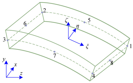
Figure A1.
Schematic of the degenerated shell element is displayed [80]. The element is degraded from a 3D solid element and has some of the properties of a solid element, enclosed by two surfaces above and below and a wraparound surface bushed by a straight line in the direction of shell thickness. It has eight nodes. and are the surface coordinates of the shell, and is the linear coordinate in the thickness direction.
In Figure A1, the nodes of the element are numbered, and the coordinates of node i (i=1, 2, ..., 8) under the global coordinate system are (xi, yi, zi); then, the coordinate values ξ and η at any point on the element surface can be expressed by interpolation in the global coordinates (x, y, z). The specific expressions are as follows:
where Ni is the shape function of the element, and the specific expression is
Within the element, displacements of points can be expressed according to node displacements and geometric relationships in the element of the middle surface, as follows:
where ai and Ni can be represented as
ai = [ui vi wi θxi θyi θzi]T, (i = 1, 2, …, 8),
Matrix B can be written as
where matrix G is a constant matrix, and can be represented as
The Jacobi matrix J is
Thus, the matrix can be written as
where E is an identity matrix of order 3 × 3 and the symbol ““ denotes the Kronecker product between two matrices.
Additionally, matrices Mξi, Mηi, and Mζican be written as
The relationship between strain and displacement in the global coordinate system can be written as
where ai(i = 1, 2, … 8) represents the displacement vector of node i within a shell element. ε represents the strain matrix. εx, εy, and εz denote the principal strain values. γxy, γyz, and γzx represent the shear strain values.
In the local coordinate system, the elasticity matrix D’ of the material is written as
where E and μ represent the elastic modulus and Poisson’s ratio. k (k = 1.2) is a constant value.
Thus, in the global system, the elasticity matrix D of the material is denoted as
where the specific expression for matrix T is given in Ref. [81].
D = TTD’T,
The position coordinate of any point on the rotation body (i.e., the blade in this paper) in the global coordinate system is denoted as r0, the corresponding elastic deformation is denoted as rA, and the position of any point relative to the fixed coordinate system is written as
Thus, the velocity at this point is written as
The absolute velocity at this point is
where
where , , and are the rotational speeds of the element around the x, y, and z axes, respectively.
The kinetic energy of the element is
The tensile and bending strain energy of the element is
where
By substituting the kinetic energy (Equation (A21)) and strain energy (Equation (A22)) of the element into the Lagrange equation, we can obtain
Therefore, the differential equation of the motion of the element is
Through assembling the stiffness matrix, mass matrix, and so on, the differential equation of the motion of the blade is established. When the external force is 0 N, the differential equation of the motion of the blade can be written as
where is the mass matrix of the blade, is the Coriolis force matrix of the blade, is the stiffness matrix of the blade, is the centrifugal stiffening matrix, and is the spin-softening matrix. C represents the Rayleigh damping matrix, and its expression can be found in Equation (7).
Appendix B
Considering the influence of angular misalignment, the minimum clearance between the ith node of the blade tip and the casing is written as [28]
where b denotes the blade width, β1 represents the misalignment angle, and β2 represents the stagger angle of the blade tips. represents minimum clearance at the first node pair. The schematic is shown in Figure 9b.
Based on the geometric relationship , the initial clearance is [28]
where Rg is the static orbit radius of the blade tips. , and ω represent the rotational speeds of the blades. Zi and Xi are the initial coordinates of the blade tip in the x and z directions. Rc is the inner radius of the casing and , where .
The dynamic clearance between the ith node pair is expressed as
where and are the radial displacement of the ith node of the casing and the blade tip, respectively.
Cao et al. [59,60,61] established a hysteresis contact-force model to simulate the contact between the blade and the coated casing. The rubbing stiffness is expressed as
where kb and kc denote the structure stiffnesses of the blade and the casing, and kh* () denotes the contact stiffness. is the local deformation of the coating. kh is the Hertz contact stiffness between the blade and the casing, and it can be written as
where vb and va denote the Poisson’s ratio of the blade and the coating, Eb and Ea are the elastic moduli of the blade and the coating, and Rg and Rc are the rotation radius of the blade tip node and the inner diameter of the casing.
The local deformation of coatings is denoted as [59]
where ks () is the structural stiffness of the blade in series with the casing. f(δi) is the penetration function, and its expression is
To calculate the damping force, Cao et al. [61] derived a normal hysteresis force model using the laws of energy conservation and momentum conservation. The normal rubbing force considering viscous damping is represented as
where is the relative initial collision velocity and is the relative collision velocity at any moment. It is solved by the difference method and , where are the clearance between blade tip node i and the casing at the jth and j−1th load steps. ce is the collision recovery coefficient, and ce = 0.8 in this paper.
When the local deformation of the coated casing meets , a hysteresis contact-force model is used to simulate the rubbing force. The overall penetration deformation meets
When the local contact stiffness of the coating is much smaller than the stiffness of the blade and casing, the rubbing stiffness is mainly determined by the local contact stiffness. The overall penetration deformation of the blade and casing is approximately equal to the local deformation of the coating. Thus, a modified Hertz contact model can be used to simulate the rubbing process between the blade and the coated casing. The overall penetration deformation meets (α = 1%). The equivalent rubbing stiffness of this model is written as [59]
When the local deformation of coatings meets , the modified linear model is used, and the equivalent rubbing stiffness is [59]
Therefore, the normal rubbing force is
The thickness of airfoil blades varies. The radial displacement and penetration depth of each node are different under the action of the centrifugal forces. Therefore, it is necessary to modify the model. The normal rubbing force of the ith node is modified as
where δ () is the sum of total penetration at each node of the blade tip.
Appendix C
The dynamic responses are calculated based on the Newmark-β method, and the coefficients utilized in the Newmark-β method are listed as
where Δt is the time step of the numerical integration. For the average acceleration method, γ0 = ½ and β0 = 1/4.
The effective stiffness matrix of the conventional Newmark-β method is written as
where Mo, Co, Go, and Ko represent the total mass, damping, gyroscope, and stiffness matrices of the system.
The effective load vector is written as
where Fe represents the total force vector.
The iterative scheme of the Newmark-β method is
References
- Wang, N.F.; Liu, C.; Jiang, D.X. Prediction of transient vibration response of dual-rotor-blade-casing system with blade off. Proc. Inst. Mech. Eng. Part G J. Aerosp. Eng. 2019, 8, 351–364. [Google Scholar] [CrossRef]
- Yu, M.Y.; Feng, Z.G.; Huang, J.J.; Zhu, L.L. A new characteristic analysis method for aero-engine rotor–stator rubbing. Proc. Inst. Mech. Eng. Part G J. Aerosp. Eng. 2017, 232, 1120–1133. [Google Scholar] [CrossRef]
- Yang, Y.; Tang, J.; Chen, G.; Yang, Y.R.; Cao, D.Q. Rub-impact investigation of a single-rotor system considering coating effect and coating hardness. J. Vib. Eng. Technol. 2021, 9, 491–505. [Google Scholar] [CrossRef]
- Millecamps, A.; Batailly, A.; Legrand, M.; Garcin, F. Snecma’s viewpoint on the numerical and experimental simulation of blade-tip/casing unilateral contacts. In Proceedings of the ASME Turbo Expo 2015: Turbine Technical Conference and Exposition, Montreal, QC, Canada, 15–19 June 2015. [Google Scholar]
- Ma, H.; Yin, F.L.; Guo, Y.Z.; Tai, X.Y.; Wen, B.C. A review on dynamic characteristics of blade–casing rubbing. Nonlinear Dyn. 2016, 84, 437–472. [Google Scholar] [CrossRef]
- Hamdi, H.; Farah, K. Beam finite element model of a vibrate wind blade in large elastic deformation. Wind. Struct. 2018, 26, 25–34. [Google Scholar] [CrossRef]
- Arumugam, A.B.; Rajamohan, V.; Pandey, A.; Sudhagar, P. Finite element vibration analysis of rotating laminated composite beam with varying cross-section using HSDT. Int. J. Interact. Des. Manuf. 2017, 11, 703–712. [Google Scholar] [CrossRef]
- Stoykov, S.; Ribeiro, P. Vibration analysis of rotating 3D beams by the p-version finite element method. Finite Elem. Anal. Des. 2013, 65, 76–88. [Google Scholar] [CrossRef]
- Gunda, J.B.; Ganguli, R. New rational interpolation functions for finite element analysis of rotating beams. Int. J. Mech. Sci. 2007, 50, 578–588. [Google Scholar] [CrossRef]
- Carassale, L.; Maurici, M.; Traversone, L. Reduced-Order Modeling of Compressor Blades by 1D Finite Elements. In Proceedings of the ASME Turbo Expo: Turbine Technical Conference and Exposition, Montréal, QC, Canada, 15–19 June 2015. [Google Scholar] [CrossRef]
- Lee, S.L. Equivalent beam modeling scheme based on three-dimensional structure with blade element concept. Adv. Compos. Mater. 2020, 29, 191–203. [Google Scholar] [CrossRef]
- Sakar, G.; Sabuncu, M. Dynamic stability of a rotating asymmetric cross-section blade subjected to an axial periodic force. Int. J. Mech. Sci. 2003, 45, 1467–1482. [Google Scholar] [CrossRef]
- Guan, H.; Ni, K.X.; Ma, H.; Xiong, Q.; Wang, W.W.; Wang, H.J. Dynamic modeling and verification of rotating compressor blade with crack based on beam element. Appl. Math. Model. 2024, 133, 367–393. [Google Scholar] [CrossRef]
- Sabuncu, M.; Evran, K. The dynamic stability of a rotating pre-twisted asymmetric cross-section blade subjected to lateral parametric excitation. Finite Elem. Anal. Des. 2006, 42, 1113–1122. [Google Scholar] [CrossRef]
- Sabuncu, M.; Evran, K. Dynamic stability of a rotating pre-twisted asymmetric cross-section Timoshenko beam subjected to an axial periodic force. Int. J. Mech. Sci. 2006, 48, 579–590. [Google Scholar] [CrossRef]
- Oh, Y.; Yoo, H.H. Vibration analysis of a rotating pre-twisted blade considering the coupling effects of stretching, bending, and torsion. J. Sound Vib. 2018, 431, 20–39. [Google Scholar] [CrossRef]
- Kou, H.J.; Du, J.J.; Liang, M.X.; Zhu, L.; Zeng, L.; Zhu, Z.D.; Zhang, F. Nonlinear characteristics of contact-induced vibrations of the rotating variable thickness plate under large deformations. Eur. J. Mech./A Solids 2019, 77, 103801. [Google Scholar] [CrossRef]
- Yao, M.H.; Ma, L.; Zhang, W. Nonlinear dynamics of the high-speed rotating plate. Int. J. Aerosp. Eng. 2018, 2018, 5610915. [Google Scholar] [CrossRef]
- Sun, J.; Kari, L.; Arteaga, I.L. A dynamic rotating blade model at an arbitrary stagger angle based on classical plate theory and the Hamilton’s principle. J. Sound Vib. 2013, 332, 1355–1371. [Google Scholar] [CrossRef]
- Rostami, H.; Ranji, A.R.; Bakhtiari-Nejad, F. Vibration characteristics of rotating orthotropic cantilever plates using analytical approaches: A comprehensive parametric study. Arch. Appl. Mech. 2018, 88, 481–502. [Google Scholar] [CrossRef]
- Luo, Z.Z.; Zhu, Y.P.; Liu, H.P.; Wang, D.Y. Dynamic similitude design method of the distorted model on variable thickness cantilever plates. Appl. Sci. 2016, 6, 228. [Google Scholar] [CrossRef]
- Chen, Y.Z.; Zhang, D.G.; Li, L. Dynamics analysis of a rotating plate with a setting angle by using the absolute nodal coordinate formulation. Eur. J. Mech./A Solids 2019, 74, 257–271. [Google Scholar] [CrossRef]
- Sinha, S.K.; Zylka, R.P. Vibration analysis of composite airfoil blade using orthotropic thin shell bending theory. Int. J. Mech. Sci. 2017, 121, 90–105. [Google Scholar] [CrossRef]
- Sun, J.; Arteaga, I.L.; Kari, L. General shell model for a rotating pretwisted blade. J. Sound Vib. 2013, 332, 5804–5820. [Google Scholar] [CrossRef]
- Júnior, C.J.F.; Cardozo, A.C.P.; Júnior, V.M.; Neto, A.G. Modeling wind turbine blades by geometrically-exact beam and shell elements: A comparative approach. Eng. Struct. 2019, 180, 357–378. [Google Scholar] [CrossRef]
- Kee, Y.J.; Shin, S.J. Structural dynamic modeling for rotating blades using three dimensional finite elements. J. Mech. Sci. Technol. 2015, 29, 1607–1618. [Google Scholar] [CrossRef]
- Yangui, M.; Bouaziz, S.; Taktak, M.; Haddar, M.; El-Sabbagh, A. Nonlinear analysis of twisted wind turbine blade. J. Mech. 2016, 34, 269–278. [Google Scholar] [CrossRef]
- Sun, Q.; Ma, H.; Zhu, Y.P.; Han, Q.K.; Wen, B.C. Comparison of rubbing induced vibration responses using varying-thicknessp-twisted shell and solid-element blade models. Mech. Syst. Signal Process. 2018, 108, 1–20. [Google Scholar] [CrossRef]
- Rafiee, R.; Tahani, M.; Moradi, M. Simulation of aeroelastic behavior in a composite wind turbine blade. J. Wind. Eng. Ind. Aerodyn. 2016, 151, 60–69. [Google Scholar] [CrossRef]
- Kee, Y.J.; Kim, J.H. Vibration characteristics of initially twisted rotating shell type composite blades. Compos. Struct. 2003, 64, 151–159. [Google Scholar] [CrossRef]
- Xiong, Q.; Guan, H.; Ma, H.; Wu, Z.Y.; Guo, X.M.; Wang, W.W. Dynamic characteristic analysis of rotating blade with breathing crack. Mech. Syst. Signal Process. 2023, 196, 110325. [Google Scholar] [CrossRef]
- Zhao, Q.; Liu, Z.L.; He, Y.H.; Yao, H.L.; Wen, B.C. Dynamic stress prediction method for rubbing blades. J. Vibroengineering 2016, 18, 1–12. Available online: https://www.extrica.com/article/16087 (accessed on 7 April 2024).
- Guan, H.; Xiong, Q.; Ma, H.; Wang, W.W.; Ni, K.X.; Wu, Z.Y.; Yin, X.M.; Zhao, S.T.; Zhang, X.X. Comparison of nonlinear vibration responses induced by edge crack and surface crack of compressor blades. Mech. Syst. Signal Process. 2024, 216, 111465. [Google Scholar] [CrossRef]
- Wang, W.W.; Ma, H.; Zhao, C.G.; Wu, Z.Y.; Wang, H.J. Dynamic contact characteristics of a rotating twisted variable-section blade with breathing crack. J. Cent. South Univ. 2024, 31, 858–877. [Google Scholar] [CrossRef]
- Ma, H.; Wang, D.; Tai, X.Y.; Wen, B.C. Vibration response analysis of blade-disk dovetail structure under blade tip rubbing condition. J. Vib. Control 2017, 23, 252–271. [Google Scholar] [CrossRef]
- Jones, S.; Legrand, M. Forced vibrations of a turbine blade undergoing regularized unilateral contact conditions through the wavelet balance method. Int. J. Numer. Methods Eng. 2015, 101, 351–374. [Google Scholar] [CrossRef]
- Sinha, S.K. Combined torsional-bending-axial dynamics of a twisted rotating cantilever Timoshenko beam with contact-impact loads at the free end. J. Appl. Mech. 2007, 74, 505–522. [Google Scholar] [CrossRef]
- Ma, X.X.; Ma, H.; Zeng, J.; Piao, Y.H. Rubbing-induced vibration response analysis of dual-rotor-casing system. Trans. Nanjing Univ. Aeronaut. Astronaut. 2018, 35, 101–108. [Google Scholar] [CrossRef]
- Zeng, J.; Ma, H.; Yu, K.; Guo, X.M.; Wen, B.C. Rubbing response comparisons between single blade and flexible ring using different rubbing force models. Int. J. Mech. Sci. 2019, 164, 105164. [Google Scholar] [CrossRef]
- Lesaffre, N.; Sinou, J.J.; Thouverez, F. Stability analysis of rotating beams rubbing on an elastic circular structure. J. Sound Vib. 2006, 299, 1005–1032. [Google Scholar] [CrossRef]
- Guo, X.M.; Zeng, J.; Ma, H.; Zhao, C.G.; Yu, X. A dynamic model for simulating rubbing between blade and flexible casing. J. Sound Vib. 2020, 466, 115036. [Google Scholar] [CrossRef]
- Zeng, J.; Ma, H.; Ma, X.X.; Wu, Z.Y.; Qin, Z.Y. Blade-loss-caused rubbing dynamic characteristics of rotor-bladed disk-casing system. Trans. Nanjing Univ. Aeronaut. Astronaut. 2018, 35, 116–125. [Google Scholar] [CrossRef]
- Batailly, A.; Legrand, M. Unilateral contact induced blade/casing vibratory interactions in impellers: Analysis for flexible casings with friction and abradable coating. J. Sound Vib. 2015, 348, 344–364. [Google Scholar] [CrossRef]
- Zhong, R.; Tang, J.Y.; Wang, A.L.; Shuai, C.J.; Wang, Q.S. An exact solution for free vibration of cross-ply laminated composite cylindrical shells with elastic restraint ends. Comput. Math. Appl. 2019, 77, 641–661. [Google Scholar] [CrossRef]
- Sun, W.W.; Zhu, M.W.; Wang, Z. Free vibration analysis of a hard-coating cantilever cylindrical shell with elastic constraints. Aerosp. Sci. Technol. 2017, 63, 232–244. [Google Scholar] [CrossRef]
- Li, C.F.; Zhong, B.F.; Shen, Z.C.; Zhang, J.R. Modeling and nonlinear vibration characteristics analysis of symmetrically 3-layer composite thin circular cylindrical shells with arbitrary boundary conditions. Thin-Walled Struct. 2019, 142, 311–321. [Google Scholar] [CrossRef]
- Dey, T.; Ramachandra, L.S. Non-linear vibration analysis of laminated composite circular cylindrical shells. Compos. Struct. 2017, 163, 89–100. [Google Scholar] [CrossRef]
- Song, X.Y.; Han, Q.K.; Zhai, J.Y. Vibration analyses of symmetrically laminated composite cylindrical shells with arbitrary boundaries conditions via Rayleigh-Ritz method. Compos. Struct. 2015, 134, 820–830. [Google Scholar] [CrossRef]
- Zhang, Y.; Sun, W.; Yang, J.; Han, Q.K. Nonlinear vibration analysis of a hard-coating cylindrical shell with elastic constraints by finite element method. Nonlinear Dyn. 2017, 90, 2879–2891. [Google Scholar] [CrossRef]
- Zhang, Y.; Sun, W.; Yang, J. A new finite element formulation for nonlinear vibration analysis of the hard-coating cylindrical shell. Coatings 2017, 7, 70. [Google Scholar] [CrossRef]
- Khan, K.; Patel, B.P.; Nath, Y. Free and forced vibration characteristics of bimodular composite laminated circular cylindrical shells. Compos. Struct. 2015, 126, 386–397. [Google Scholar] [CrossRef]
- Ma, H.; Tai, X.Y.; Han, Q.K.; Wu, Z.Y.; Wang, D.; Wen, B.C. A revised model for rubbing between rotating blade and elastic casing. J. Sound Vib. 2015, 337, 301–320. [Google Scholar] [CrossRef]
- Ma, H.; Yin, F.L.; Tai, X.Y.; Wang, D.; Wen, B.C. Vibration response analysis caused by rubbing between rotating blade and casing. J. Mech. Sci. Technol. 2016, 30, 1983–1995. [Google Scholar] [CrossRef]
- Zhou, T.; Jia, Y.F.; Zou, L.M.; Jiang, Z.N.; Wang, W.M.; Hu, M.H. Vibration characteristics of blade-casing rubbing fault considering rotor–stator coupling. Mech. Syst. Signal Process. 2024, 218, 111589. [Google Scholar] [CrossRef]
- Hou, Y.H.; Cao, S.Q.; Kang, Y.H. Study on the frequency modulation phenomenon in the rotor system with blade-casing rub-impact fault. Int. J. Non-Linear Mech. 2024, 159, 104626. [Google Scholar] [CrossRef]
- Wu, Z.Y.; Zhao, L.C.; Yan, H.; Yan, G.; Chen, A.; Zhang, W.M. Multi-blade rubbing characteristics of the shaft-disk-blade-casing system with large rotation. Appl. Math. Mech. 2024, 45, 111–136. [Google Scholar] [CrossRef]
- Shao, J.; Wu, J.G.; Yang, K.; Zhang, Y. Dynamic characteristic analysis of a twin-spool rotor–casing system with looseness and intershaft rubbing coupling faults. J. Mech. Sci. Technol. 2024, 38, 101–120. [Google Scholar] [CrossRef]
- Li, B.Q.; Ma, H.; Zeng, J.; Guo, X.M.; Wen, B.C. Rotating blade-casing rubbing simulation considering casing flexibility. Int. J. Mech. Sci. 2018, 148, 118–134. [Google Scholar] [CrossRef]
- Yang, Y.; Cao, D.Q.; Wang, D.Y. Investigation of dynamic characteristics of a rotor system with surface coatings. Mech. Syst. Signal Process. 2017, 84, 469–484. [Google Scholar] [CrossRef]
- Yang, Y.; Ouyang, H.J.; Wu, X.L.; Jin, Y.L.; Yang, Y.R.; Cao, D.Q. Bending-torsional coupled vibration of a rotor-bearing-system due to blade-casing rub in presence of non-uniform initial gap. Mech. Mach. Theory 2019, 140, 170–193. [Google Scholar] [CrossRef]
- Cao, D.Q.; Yang, Y.; Chen, H.T.; Wang, D.Y.; Jiang, G.Y.; Li, C.G.; Wei, J.; Zhao, K. A novel contact force model for the impact analysis of structures with coating and its experimental verification. Mech. Syst. Signal Process. 2016, 70, 1056–1072. [Google Scholar] [CrossRef]
- Zeng, J.; Zhao, C.G.; Ma, H.; Yu, K.; Wen, B.C. Rubbing dynamic characteristics of the blisk-casing system with elastic supports. Aerosp. Sci. Technol. 2019, 95, 105481. [Google Scholar] [CrossRef]
- Kang, Y.H.; Cao, S.Q.; Gao, T.; You, Z.Z. Development and validation of a rotating blade-casing rubbing model by considering the blade deformation and abradable coating. J. Sound Vib. 2023, 563, 117853. [Google Scholar] [CrossRef]
- Kang, Y.H.; Cao, S.Q.; Hou, Y.H.; Chen, N.; Li, B. Dynamics research on the rubbing process and rubbing forms of rotor–blade–casing systems. Int. J. Non-Linear Mech. 2022, 147, 104242. [Google Scholar] [CrossRef]
- Jin, M.; Wang, A.L.; Wang, Q.S.; Wang, L.K. Rub-impact dynamic analysis of the central tie rod rotor-blade-casing coupling system with the Hirth couplings connection. J. Vib. Eng. Technol. 2024, 12, 1479–1503. [Google Scholar] [CrossRef]
- Tang, T.; Wang, Y.; Chen, Z.Y.; Wang, S.; Zhang, M.Q. Study on rubbing characteristics of blade-casing model considering transverse cracks. J. Sound Vib. 2023, 567, 117928. [Google Scholar] [CrossRef]
- Wang, N.F.; Liu, C.; Jiang, D.X.; Kamran, B. Casing vibration response prediction of dual-rotor-blade-casing system with blade-casing rubbing. Mech. Syst. Signal Process. 2019, 118, 61–77. [Google Scholar] [CrossRef]
- Wang, N.F.; Liu, C.; Jiang, D.X. Experimental analysis of dual-rotor-support-casing system with blade-casing rubbing. Eng. Fail. Anal. 2021, 123, 105306. [Google Scholar] [CrossRef]
- Zhang, J.H.; Lu, X.; Lin, J.W.; Ma, L.; Dai, H.W. Dynamic characteristics analysis of blade-casing rubbing faults with abradable coatings. Proc. Inst. Mech. Eng. Part C J. Mech. Eng. Sci. 2021, 235, 975–987. [Google Scholar] [CrossRef]
- Jin, Y.L.; Liu, Z.W.; Yang, Y.; Li, F.S.; Chen, Y.S. Nonlinear vibrations of a dual-rotor-bearing-coupling misalignment system with blade-casing rubbing. J. Sound Vib. 2021, 497, 115948. [Google Scholar] [CrossRef]
- Salvat, N.; Batailly, A.; Legrand, M. Modeling of abradable coating removal in aircraft engines through delay differential equations. J. Eng. Gas Turbines Power 2013, 135, 102102. [Google Scholar] [CrossRef]
- Kammer, A.S.; Olgac, N. Blade/Casing rub interaction in turbomachinery: Structural parameters’ influence on stability. J. Propuls. Power 2016, 32, 928–938. [Google Scholar] [CrossRef]
- Berthoul, B.; Batailly, A.; Stainier, L.; Legrand, M.; Cartraud, P. Phenomenological modeling of abradable wear in turbomachines. Mech. Syst. Signal Process. 2018, 98, 770–785. [Google Scholar] [CrossRef]
- Legrand, M.; Batailly, A.; Pierre, C. Numerical investigation of abradable coating removal in aircraft engines through plastic constitutive law. J. Comput. Nonlinear Dyn. 2012, 7, 011010. [Google Scholar] [CrossRef]
- Batailly, A.; Legrand, M.; Millecamps, A.; Garcin, F. Numerical-experimental comparison in the simulation of rotor/stator interaction through blade-tip/abradable coating contact. J. Eng. Gas Turbines Power 2012, 134, 082504. [Google Scholar] [CrossRef]
- Batailly, A.; Cuny, M.; Legrand, M.; Philippon, S. Numerical-experimental confrontation in the simulation of tool/abradable material interaction. J. Eng. Gas Turbines Power 2013, 135, 062102. [Google Scholar] [CrossRef]
- Almeida, P.; Gibert, C.; Thouverez, F.; Leblanc, X.; Ousty, L.P. Numerical analysis of bladed disk–casing contact with friction and wear. J. Eng. Gas Turbines Power 2016, 138, 122802. [Google Scholar] [CrossRef]
- Almeida, P.; Gibert, C.; Thouverez, F. On Some Physical Phenomena Involved in Blade-Casing Contact. In Proceedings of the Eurodyn-International Conference on Structural Dynamics, Porto, Portugal, 30 June—2 July 2014; Available online: https://hal.science/hal-02121521/ (accessed on 7 April 2024).
- Ma, H.; Guan, H.; Qu, L.; Yang, T.R.; Zeng, Y.; Chen, Y.Y.; Zhu, Z.M.; Wang, H.J. Blade-coating-casing rubbing induced vibration responses and wear characteristics. Tribol. Int. 2024, 194, 109571. [Google Scholar] [CrossRef]
- Guan, H.; Ma, H.; Qu, X.C.; Wu, Z.; Zeng, J.; Xiong, Q.; Wang, H. Dynamic stress analysis of cracked rectangular blade: Simulation and experiment. Int. J. Mech. Sci. 2024, 267, 109015. [Google Scholar] [CrossRef]
- Zhao, T.Y.; Li, K.; Ma, H. Study on dynamic characteristics of a rotating cylindrical shell with uncertain parameters. Anal. Math. Phys. 2022, 12, 97. [Google Scholar] [CrossRef]

Disclaimer/Publisher’s Note: The statements, opinions and data contained in all publications are solely those of the individual author(s) and contributor(s) and not of MDPI and/or the editor(s). MDPI and/or the editor(s) disclaim responsibility for any injury to people or property resulting from any ideas, methods, instructions or products referred to in the content. |
© 2024 by the authors. Licensee MDPI, Basel, Switzerland. This article is an open access article distributed under the terms and conditions of the Creative Commons Attribution (CC BY) license (https://creativecommons.org/licenses/by/4.0/).