Article

Topology Analysis and Structural Optimization of Air Suspension Mechanical-Vibration-Reduction Wheels

1
School of Mechanical Engineering, Shandong University, Jinan 250061, China
2
Qingdao Shuangxing Equipment Manufacturing Co., Ltd., Qingdao 266400, China
*
Author to whom correspondence should be addressed.
Machines 2024, 12(7), 488; https://doi.org/10.3390/machines12070488
Submission received: 27 June 2024 / Revised: 15 July 2024 / Accepted: 16 July 2024 / Published: 19 July 2024
(This article belongs to the Section Machine Design and Theory)

Abstract

:
This paper designs a kind of air suspension mechanical-vibration-reduction wheel for mining engineering vehicles; the research work on topology analysis and the structural optimization of the inner and outer rims are carried out with this wheel as the research object. Using Workbench finite-element analysis software, taking the results of static analysis and modal analysis of the two as constraints, a variety of structural improvement styles are obtained through a topology analysis method and compared and verified, and a more reasonable improvement result is selected and assembled into a whole wheel for final analysis and verification. The results show that the optimization results of the wheel still meet the design’s load-bearing requirements, and the weight is lighter; the topology analysis results are ideal.

1. Introduction

At present, most vehicles used in daily life are the main culprits for destroying the environment; the development demand for vehicles with low energy consumption, low emissions, and high performance is imminent, and the lightweight treatment of vehicles is an important means of realizing this demand.
Normally, the lightweight treatment of the whole vehicle is beneficial for improving its dynamic performance, and reducing the unsprung weight of the vehicle will further improve its handling performance. A vehicle’s lower unsprung weight can reduce the moment of inertia of the wheel; greatly shorten the response time of the vehicle to the driver’s operation; and accelerate the starting speed, parking speed, and steering speed of the vehicle. In addition, under rugged road conditions, a lower unsprung weight of the vehicle can reduce the working strength of the suspension assembly. Therefore, for the unsprung part of the vehicle, a lightweight wheel design will derive a more effective optimization outcome compared with the whole vehicle.
In the early stages, our team put forward a kind of air suspension mechanical-vibration-reduction wheel to solve the outstanding problems of safety, environmental protection, and cushioning vibration reduction faced by mining wheels. But at the beginning of the design, the key requirement of a wheel design is that it should have good bearing capacity and meet the strength conditions of the structure and material; additionally, it should not consider the structural layout or weight limitation too much because such considerations may easily lead to unreasonably detailed layouts and excessive wheel weight (the wheel weight has reached 3686 kg). An overweight wheel will lead to an increase in the wheel’s moment of inertia, a reduction in a vehicle’s cruising range, and a reduction in handling performance. In order to avoid these unfavorable results, it is necessary to optimize the wheel structure to optimize a detailed layout and reduce the overall weight of the wheel as much as possible on the premise of meeting structural strength and bearing requirements. In this paper, the analysis method of topology optimization will be used to complete the optimization of the wheel.
Topology optimization is a structural optimization method for finding the optimal topological configuration or material distribution of objects in a limited space. This method has the advantage of obtaining innovative configurations without depending on the designer’s experience. In recent decades, it has developed rapidly and played a significant role in many fields, such as aerospace [1,2,3], automobile design [4,5], ship design [6,7], and rail transit [8,9].
In the field of wheels, Jinsu [10] used the solid-shell finite-element model to optimize the topology of the steel wheel; this was performed to maximize the first rim-mode frequency on the premise of satisfying a rotational inertia constraint. The experimental results show that the first rim-mode frequency of the steel wheel is obviously increased from 164 Hz to 262 Hz, and the driving noise is reduced by 2.2 dB. Zhang [11] combined the topology optimization model with multi-design spaces and multi-load cases; the combination of gray relational analysis (GRA) and principal component analysis (PCA) was simultaneously integrated into a multi-objective topology optimization (MOTO) method. As a result of optimization, a variety of wheel topology layouts with improved impact resistances were obtained, and the natural frequencies of the wheel met the requirements. Chu [12] used the technologies of simulation analysis, dimension optimization, and topology optimization to analyze the performance of the new wheel. When the wheel met the performance requirements and test methods of commercial vehicles wheels (GB/T5909-2009) [13], the material weight loss of the product reached 48% and the structure weight loss reached 13.8%. Wang [14] adopted a wheel structural design process and multi-objective optimization method based on fatigue; with 13° impact and 90° impact test performances, the weight of the optimized assembled wheel was 28.59% less than that of the same type, a cast-aluminum alloy wheel. The correctness of the finite-element model is verified by comparing the simulation and test values of the equivalent strain and maximum acceleration at the measuring points. Jang [15] put forward a systematic and efficient tool for designing the topological patterns of a non-pneumatic wheel. Three representative patterns were chosen and analyzed for possible applications under working conditions. Peter [16] put forward and analyzed a topologically optimized tire that better conforms with the design parameters of mining vehicles; they proved the feasibility of replacing standard commercial pneumatic or foam-filled tires with specially designed airless tires, thus better serving the mining market. K [17] used the topology optimization method to reduce the excess material of the wheel hub of an all-terrain vehicle (ATV) and reduce the weight. Shuai [18] combined the contribution analysis method, the modified NSGA-II, and the entropy weight gray relation analysis (EGRA) to optimize the assembly wheel. The result demonstrates that the weight reduction in the assembled wheel after optimization is 4.49%; the bending fatigue life and the radial fatigue safety factor were reduced by 9.95% and 25%, respectively. According to the results of the wheel-hub-parameter-sensitive figure, the fatigue analysis, and the topology wheel movement curve area under impact load, Z [19] optimized the shape of the wheel hub model based on topological optimization; after topology optimization, the hub weight was reduced to 16%. According to per-impact loading and other boundary conditions, J [20] carried out finite-element analysis and achieved a weight reduction of about 60% through the topology optimization of various wheel assembly components, such as the front and rear knuckles and hubs.

2. Materials and Methods

2.1. Design and Development of Air Suspension Mechanical-Vibration-Reduction Wheel

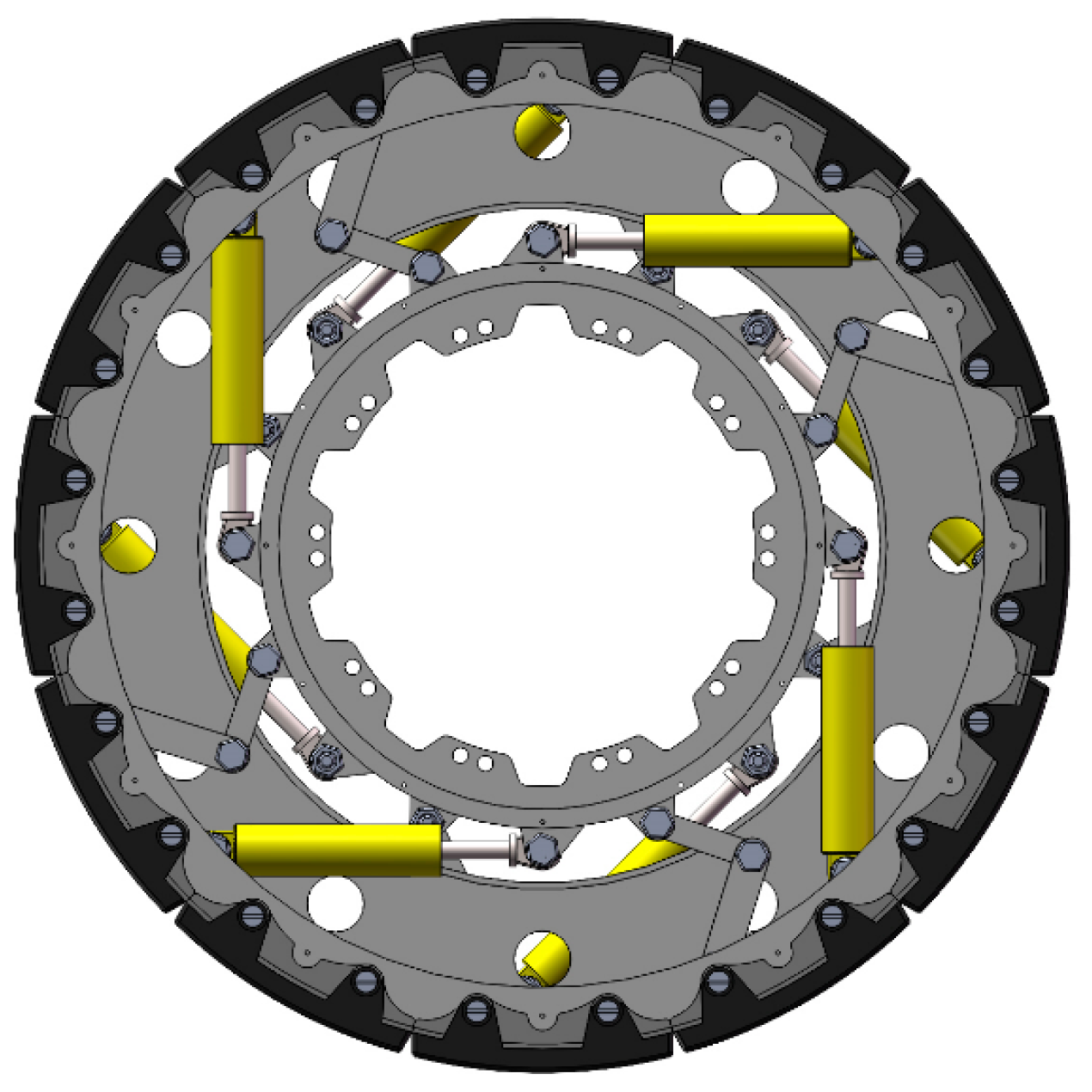
Under the cooperation of Qingdao Xinghua Intelligent Company, considering the design requirements of wheel size and the design idea of the air suspension wheel (ASW) of the GACW Company of the United States [21], the overall specifications of the wheel are 27.00/R49 common dimensions of mining wheels, with a standard design load of 45 T. The structural design of the new wheel is completed using SolidWorks simulation modeling software, with the basic design scheme shown below: the wheel is primarily composed of an outer rim, an inner rim, a non-pneumatic tire skin, a pneumatic spring, and a transverse brake, as indicated in Figure 1.
Assemble all parts according to the design requirements to obtain the initial assembly of the air suspension mechanical-vibration-reduction wheel, as shown in Figure 2.
In addition, the important dimensions of the wheel can be obtained as shown in Table 1.

2.2. Topology Optimization Analysis Method

At present, the main methods comprise the following: homogenization method [22], solid isotropic material with penalization (SIMP) method [23,24], level set method [25,26], evolutionary structural optimization method [27,28], moving morphable components (MMC) method, and moving morphable void (MMV) method [29,30,31]. In this paper, the SIMP method is mainly used to complete the topology optimization analysis of the wheel.
SIMP is a method that discretizes a continuous whole into a finite-element model and specifies that each small element has the same density; then, it uses this density as a design variable, the model’s minimum flexibility as an optimization objective function, and the weight constraint (or volume constraint) and material equilibrium condition to solve the optimization problem.
The mathematical model of structural topology optimization based on the SIMP method is as follows:
Find : X = x 1 , x 2 , x 3 , , x n T R min : C ( X ) = i = 1 N u i T k i u i = i = 1 N x i p u i T k 0 u i s . t . V ( X ) θ V 0 = i = 1 N x i V i
The format is as follows: X is the design variable, indicating the element’s density; C(X) is the objective function of the static strain energy of the structure; Ki is the element stiffness after interpolation; P is the penalty factor; K0 is the initial element stiffness; V(X) is the volume of the optimized region; θ is in the interval of [0, 1], which is the volume constraint value; V0 is the initial volume of the optimization model; Vi is the unit of volume.

2.3. Topology Optimization Analysis Process

For the wheel discussed in this work, establishing the assumption that the distribution and arrangement of its internal elements will not change is required. Because the weight ratio of the pneumatic spring and transverse brake in the wheel is relatively small, the effect of structural optimization is not obvious, and it is easy to affect the wheel’s bearing capacity; thus, only two larger parts, the inner and outer rims, are chosen to complete the topology optimization analysis operation.
The general operation flow of topology optimization analysis is shown in Figure 3. First, a static or modal analysis of the inner and outer rims is needed. In the early stage, the static analysis of the whole wheel and the modal analysis of the inner and outer rims have been completed, and the corresponding static analysis needs to be completed by separately extracting the supporting reaction force of the inner and outer rims. Then, the constraint conditions of the inner and outer rims are set, the areas that need to be optimized and reserved are selected, and the finite-element analysis model of the topology optimization of the inner and outer rims is established. The topology optimization analysis results of the two rims are obtained by using the methods of repeated iteration and cyclic optimization. Finally, according to the optimization results, the inner and outer rims are improved, and the strength and performance of the improved structure are verified to meet the original design requirements.

3. Analysis Process and Optimization Results

3.1. Inner Rim

3.1.1. Establish a Topology Optimization Analysis Model

Supporting Reaction Force of Inner Rim

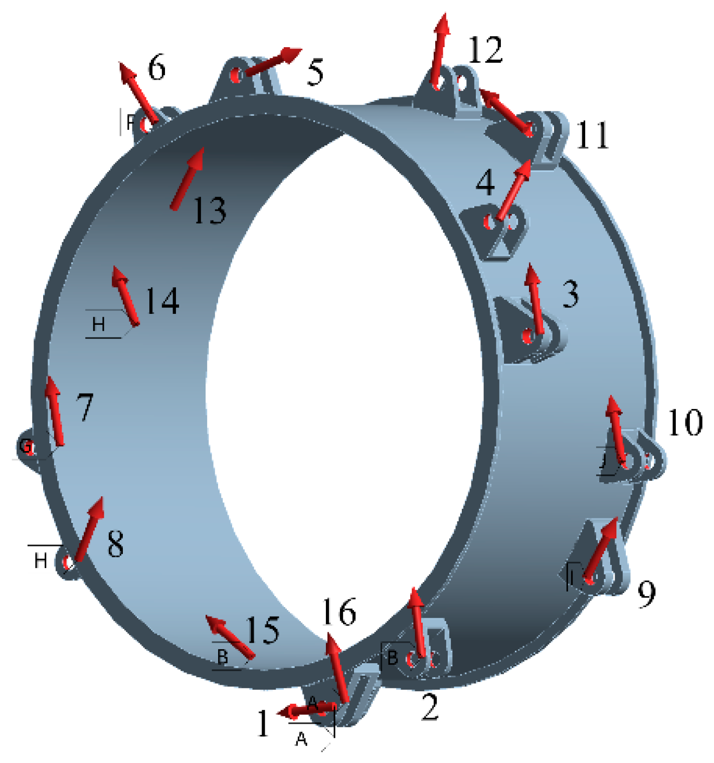
Under the vertical load of 45 T required by the design, the stress of the inner rim is shown in Figure 4, in which eight odd numbers are pneumatic spring lugs and eight even numbers are transverse brake lugs. The red arrow only indicates the direction of the supporting reaction force borne by each lug of the inner rim when the wheel is subjected to vertical loads, and it does not represent the numerical value of the force.
The coordinate system of the inner rim in space can be expressed as follows: The coordinate origin is located on the left side of the inner rim; the positive direction of the Y axis denotes that the inner surface axis of the inner rim proceeds from left to right; the positive direction of the X axis denotes that the vertical radial direction of the inner rim proceeds from top to bottom; the positive direction of the Z axis denotes that the horizontal radial direction of the inner rim proceeds from left to right. Under the vertical load of 45 T, the supporting reaction force of the inner rim is shown in Table 2, and the numbers 1–16 in the table correspond to the lugs in Figure 4.

Setting Mesh

Topology optimization analysis is used to discretize the continuum into finite density elements and then analyze and re-integrate them under the restriction of constraints and optimization areas. The quality of the mesh seriously affects the accuracy of the analysis results. Generally, hexahedral mesh can obtain better optimization results, but the structure of the inner rim is complex and cannot be forcibly divided into hexahedral mesh. In order to ensure the smooth completion of optimization analysis, the tetrahedral mesh method is selected to divide the mesh of the inner rim. When the mesh size is set to 9 mm, the final number of elements generating the mesh is 671,391, the number of nodes is 1,056,040, and the quality of the mesh is 0.83847, which meets the accuracy requirements of topology optimization analysis.

Constraints and Optimization Areas

The inner rim topology optimization analysis requires that the static or modal analysis be completed first. This time, it is essential to extract the inner rim model independently, set each supporting reaction force in Table 2 at each lug to complete the static analysis, and then use the static analysis result as the constraint condition for the topological analysis.
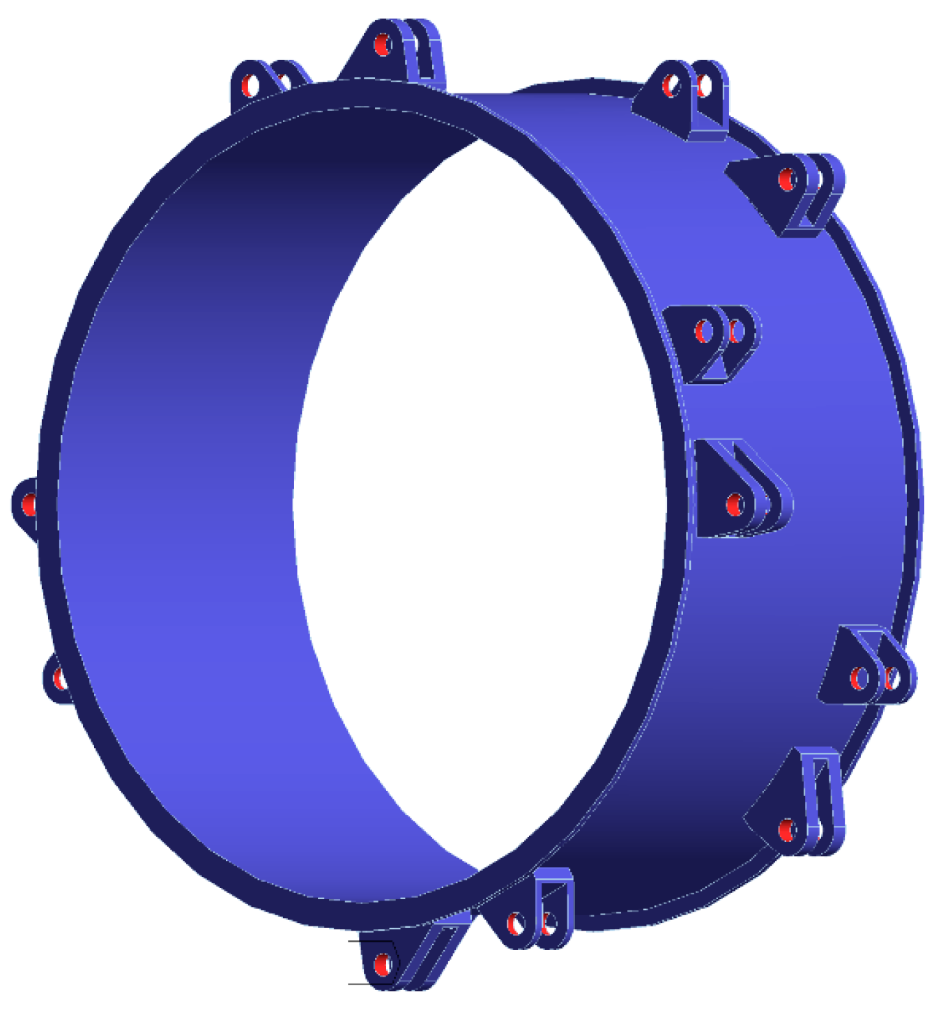
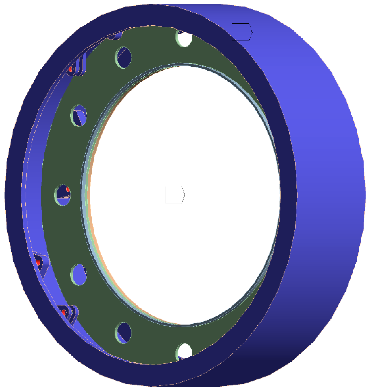
The whole inner rim is selected as the design area for topology optimization (blue), and 32 cylindrical surfaces at the joint of pneumatic spring lugs and transverse brake lugs and the corresponding parts are selected as the exclusion area (red). The model setting is shown in Figure 5.

Optimization Analysis Parameters

The maximum number of iteration steps is set to 500 times, the minimum standardized density is set to 0.001, the convergence accuracy is set to 0.1% (indicating the ease of convergence, and the smaller the numerical value, the higher the accuracy), and the penalty factor is set to 3 (indicating the fineness of optimization, and the numerical value is generally kept within the range of 3–6). In order to ensure the accuracy and effectiveness of the analysis results, this optimization analysis process mainly selects three optimized states with weight retention ratios for comparative analysis.

3.1.2. Optimization Results and Analysis

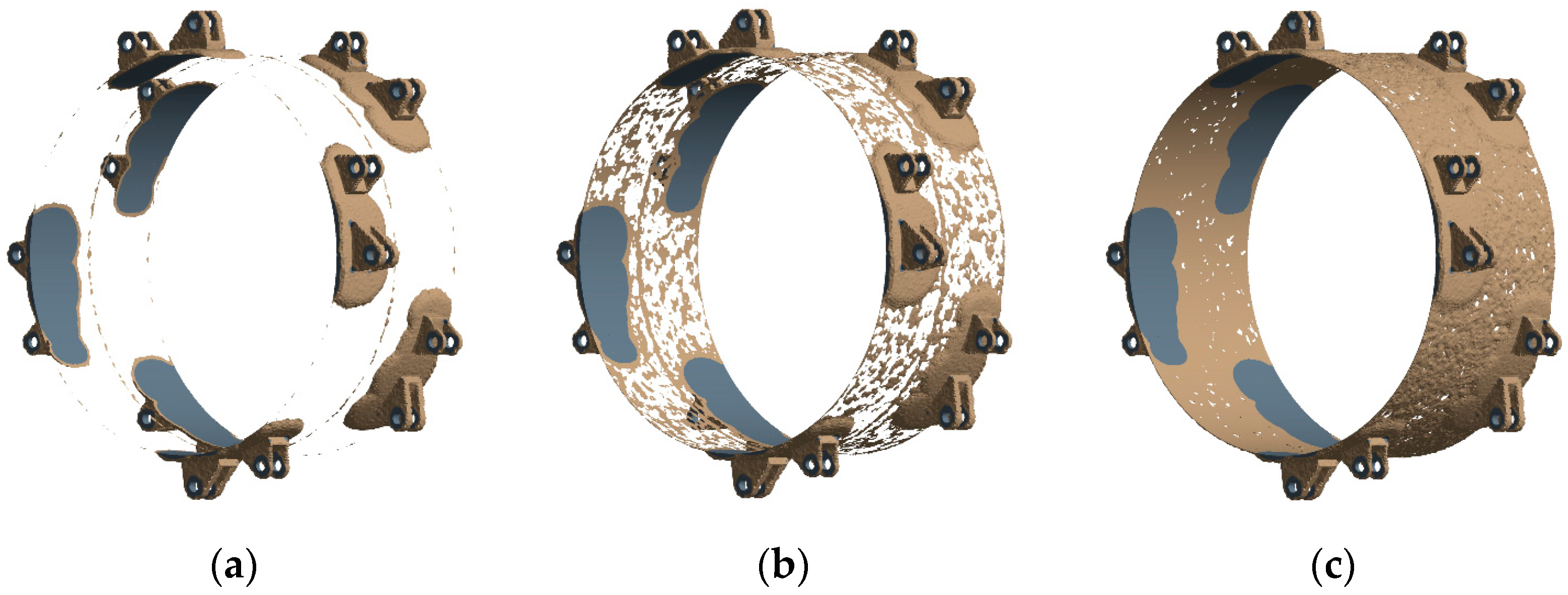
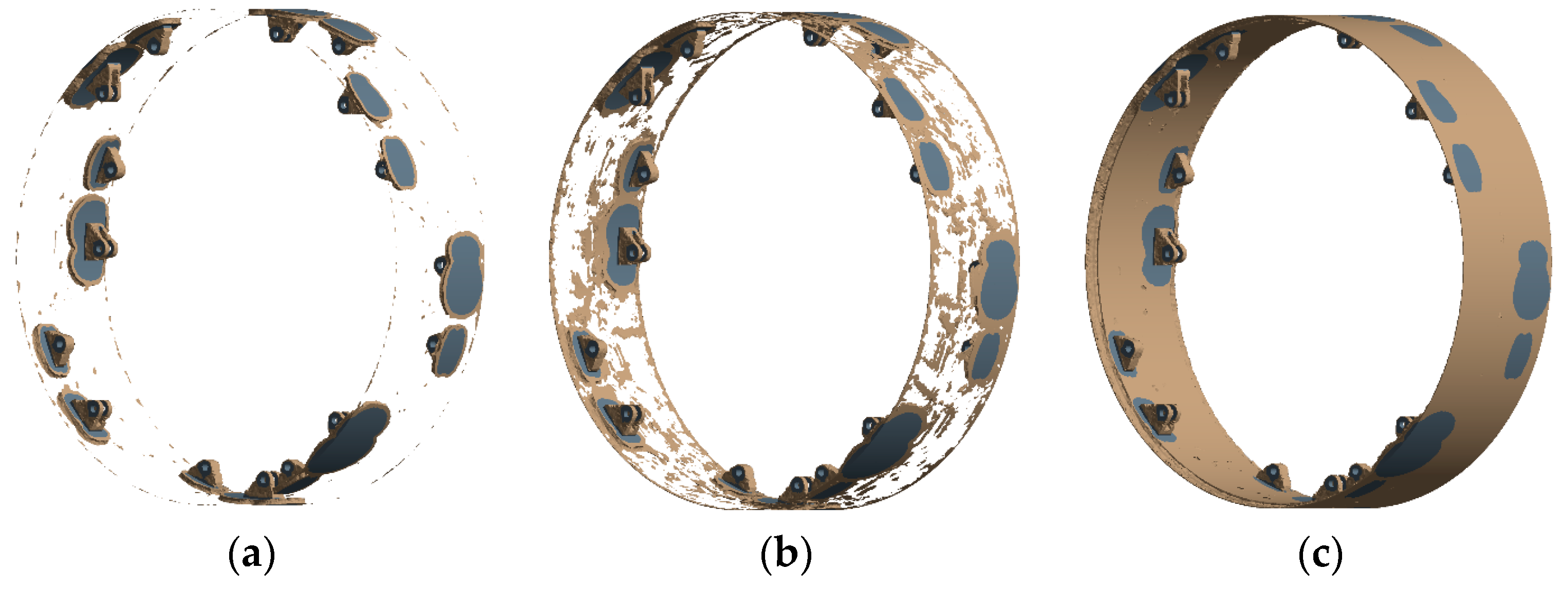
The topology optimization analysis process of the inner rim has been iterated many times, and preliminary optimization results have been obtained. The topology optimization result models under three conditions of weight retention ratio are shown in Figure 6.
Three optimization results are obtained for the inner rim: The original weight retention percentage of result 1 is 46.41%, and the corresponding optimization result shows that only the area near each lug is retained, and most other areas are discarded, but it is obvious from Figure 6a that the reserved areas of result 1 are separated from each other and basically have no reference value. The original weight retention percentage of result 2 is 51.186%, and the corresponding optimization result shows that on the basis of retaining the area near the lug, there is an intermittent retaining structure among the reserved areas, and an obvious ring structure is retained in the middle of the main body (as shown in Figure 6b); the reserved area is increased, which shows that the area near the non-lug can be properly removed under the premise of ensuring structural strength, but it is best to retain the ring structure in the middle of the main body. Although the optimized model structure has taken shape, the optimization result is also for reference only, and there is still a big gap within the real applicable structure. The original weight retention percentage of result 3 is 56.756%, the reserved area is further increased, and the inner rim main body area is basically retained, but the thickness of the main body near the non-lug area is reduced (as shown in Figure 6c). As a result of this optimization, the thickness of the main body is reduced, which will inevitably affect the structural strength of the inner rim and easily cause its crushing deformation, so result 3 is also not feasible.
Considering the above three optimization results, results 1 and 3 are basically not feasible, while result 2 can be used as the original model for further fine optimization and subsequent structural improvement.

3.1.3. Structural Improvement Design Scheme

After topology optimization analysis, the structural improvement of the inner rim is selected with result 2 as the optimization scheme, that is, the area near the lug is reserved and the area near the non-lug is hollowed out. This method is bound to reduce the weight of the inner rim, but it is not enough to discuss the structural optimization of the object, only the structural lightweight is based on topology optimization. The blind pursuit of lightweight properties may lead to the opposite results. It is necessary to realize a lightweight inner rim structure while ensuring structural strength and also to take into account the ability of the structure to resist excitation resonance.
The modal characteristics of the inner rim are discussed in the early stages. From the results, it can be seen that the area with the largest amplitude is basically concentrated on the main body, including the overall extrusion, stretching and shaking, local protrusion, and compression deformation. Because the wall thickness of the inner rim body is lower than the diameter, it is similar to the thin-walled cylinder structure as a whole, and its ability to resist resonance is weak. In order to improve its anti-vibration ability, increasing the wall thickness of the inner rim body is the most effective way on the premise that the diameter of the structure cannot be changed. At the same time, limited by the premise of lightweight structure, the overall increase in wall thickness will inevitably lead to a synchronous increase in structural weight, so the support ring can be installed in local areas to improve its anti-vibration ability.
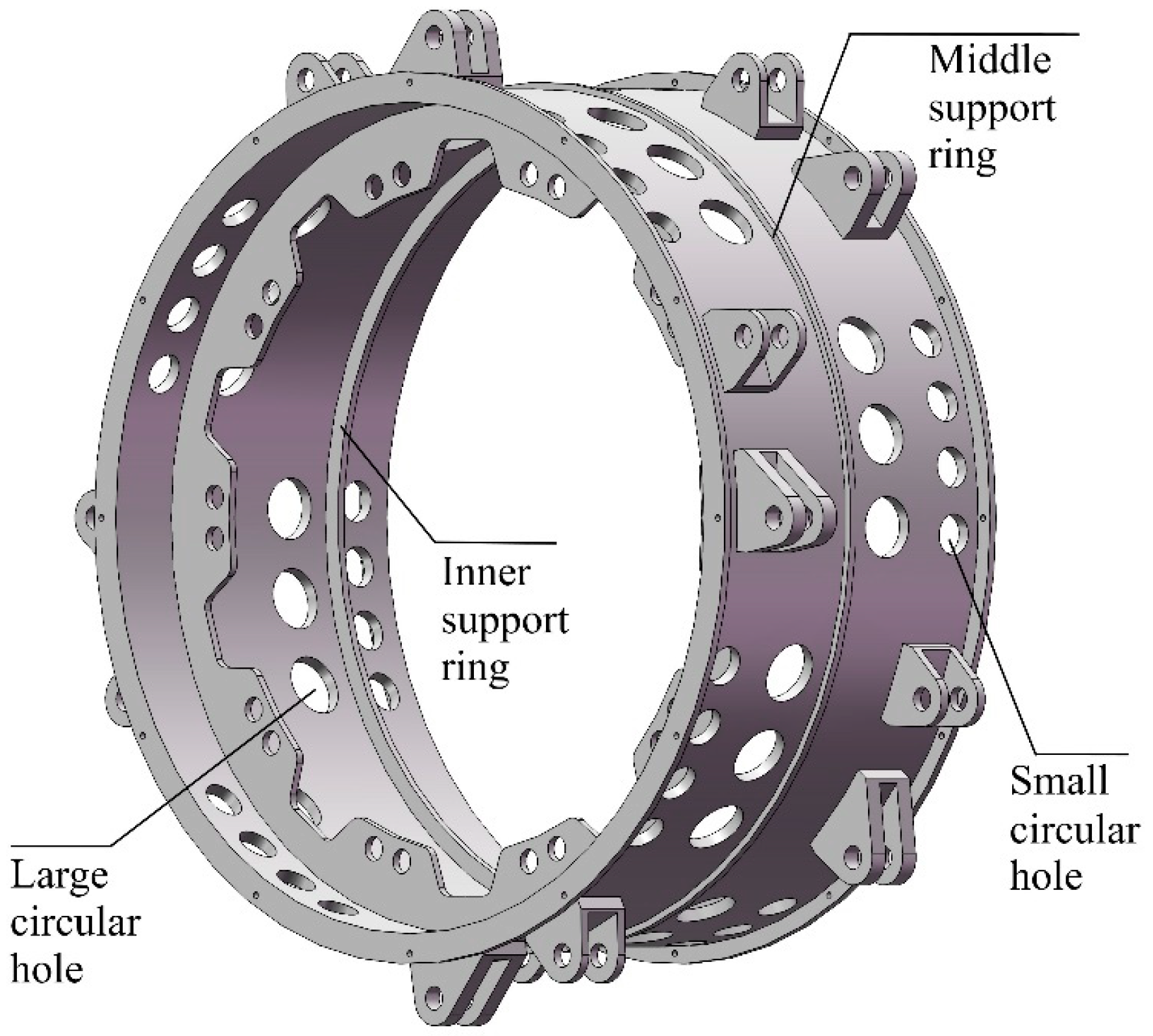
Based on the above analysis, the final optimization scheme of the inner rim adopts the dual-track parallel mode of hollowing out the area near the non-lug and installing the support ring in the local area of the main body. Because methods for hollowing out and installing support rings are not fixed and vary, in order to minimize the influence of stress concentration, this paper adopts the circular hollowing-out method. Considering topology optimization result 2 and previous modal results, two support rings are installed in the middle part of the main body, and the symmetrical position of the flange is fixedly connected with the axle bolt to complete the structural optimization and improvement of the inner rim. Although the improvement scheme has been basically determined, the specific improvement results are still varied, and it is impossible to verify every result, so this paper only selects one of the improvement results for discussion, and the specific optimization setting of the inner rim is shown in Figure 7.
The concrete improvement results are as follows: A middle support ring is added to the middle part of the outer side of the inner rim body; an inner support ring is added to the symmetrical position of the flange plate fixedly connected with the axle bolt; 24 large circular holes are drilled between the flange plate and the inner support ring; 32 small circular holes are drilled outside the flange plate and the inner support ring, among which 3 large holes and 4 small holes are a group, and each group of through holes is located in the area near the non-lug: that is, the hollowed position of the previous result 2. Because the reserved area near the lug of optimization result 2 is not clearly quantified, in order to realize the strength requirements of the inner rim as much as possible, the range of the reserved area near the lug is appropriately increased; that is, the edge of each group of through holes does not exceed the two end faces of the axially corresponding lug.
Although the improvement result selected in this section is only one of many results, the feasibility of the improvement result can also be discussed by changing the specific parameter settings, including the diameters of large holes and small holes and the diameters of two support rings. This paper selects four groups of parameter settings to complete the discussion, and the specific parameters are shown in Table 3.
Four kinds of improvement results were obtained by changing the parameter settings of the optimized parts, which will be further verified in the future, and then the best improvement result under this optimization scheme will be selected.

3.2. Outer Rim

3.2.1. Establish a Topology Optimization Analysis Model

Supporting Reaction Force of Outer Rim

The topology optimization analysis of the outer rim is based on the same premise as that of the inner rim. Also, under the condition of a 45 T design load on the wheel, the supporting reaction force of each lug of the outer rim is extracted, as shown in Figure 8, in which eight odd numbers are pneumatic spring lugs and eight even numbers are transverse brake lugs. The red arrow only indicates the direction of the supporting reaction force borne by each lug of the outer rim when the wheel is subjected to vertical loads and does not represent the numerical value of the force.
The supporting reaction force on the extracted outer rim is shown in Table 4, and the numbers 1–16 in the table correspond to the lugs in Figure 8.

Setting Mesh

The mesh setting method of the outer rim is the same as that of the inner rim, and the mesh size is set at 15 mm. Finally, the number of elements generating the mesh is 574,085, the number of nodes is 943,096, and the quality of the mesh is 0.84407. The mesh setting results meet the requirements of simulation accuracy and can be used for subsequent topology optimization analysis.

Constraints and Optimization Areas

The topology optimization analysis of the outer rim also needs to consider the results of static and modal analyses so that the selection of constraint conditions is the same as that of the inner rim mentioned above. In addition, because the inner support plate of the outer rim is an important structure for supporting the outer rim body and preventing the body from being crushed, the inner support plate will be excluded from the optimized design area, and only the main body part of the outer rim will be optimized and analyzed, as shown in the blue area in Figure 9; the 24 cylindrical surfaces of the outer rim connecting with the pneumatic spring lugs and the transverse brake lugs will be excluded (as shown in the red area).

Optimization Analysis Parameters

The optimization analysis parameters of the outer rim are exactly the same as those of the inner rim in the previous article; there is not much description here.

3.2.2. Optimization Results and Analysis

The outer rim has completed the topology optimization analysis under the condition of supporting the reaction force, and the optimization models under the conditions of three weight retention ratios are obtained, as shown in Figure 10.
The optimization results of the outer and inner rims are similar, and the optimized exclusion areas are mainly concentrated on the main body. The original weight retention percentage of result 1 is 29.627%; the corresponding optimization result shows that only the areas near the lugs are retained, and most other areas are discarded. As can be clearly seen in Figure 10a, result 1 basically has no reference value because the reserved areas are separated from each other. The original weight retention percentage of result 2 is 38.79%, and the corresponding optimization result shows that the retention area is increased on the basis of result 1. As can be seen in Figure 10b, the increased retention area is mostly near the non-lug, and this result can be used as a reference model for further refinement and improvement. The original weight retention percentage of result 3 is 44.405%, and the reserved area is further increased. While the main body area of the outer rim is basically retained, only the thickness of the main body in the area near the non-lug is reduced (as shown in Figure 10c). However, such optimization results will inevitably weaken the structural strength of the outer rim and easily lead to crushing deformation, so result 3 is not feasible.
Considering the above three optimization results, results 1 and 3 are basically not feasible, and result 2 can be used as the original model for further refinement and improvement, which can be used to complete subsequent optimization and improvement work.

3.2.3. Structural Improvement Design Scheme

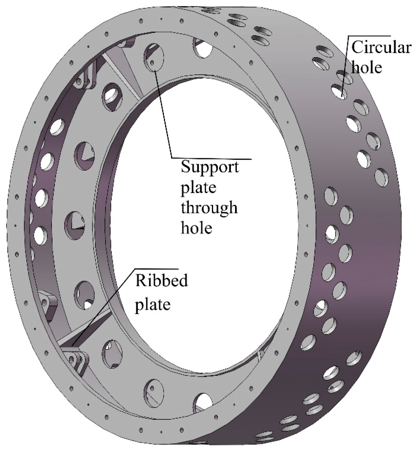
The structural improvement and optimization of the outer rim are mainly based on the optimized model of result 2; that is, the area near the non-lug of the main body of the outer rim is hollowed out, and the circular hollowing out is adopted as the optimization method of the inner rim. In addition, from the modal analysis results of the outer rim, it can be seen that when the outer rim resonates, the larger vibration area is mostly concentrated on the inner support plate, and the support plate will swing back and forth or wave to a large extent. In order to strengthen the support plate, reduce its vibration, and improve the anti-vibration performance of the outer rim, the method of installing multiple ribbed plates on both sides of the support plate is selected. Therefore, the optimization and improvement measures for the outer rim mainly include two aspects: the circular through hole of the main body and the ribbed plate of the support plate. The improvement scheme has been basically determined, but the number and position of the specific through holes and ribbed plates are not fixed. Only one operation mode is selected for discussion in this section, and the specific optimized setting of the outer rim is shown in Figure 11.
The specific optimization scheme of the outer rim is as follows: According to the results of the previous statics, the stress response of the inner support plate of the outer rim is not obvious under the ultimate load of 45 T, so the original 12 support plate through holes can be increased to 16 in the initial stage of optimization design so that the weight can be reduced as much as possible without affecting the structural strength, and this adjustment is a prerequisite for optimization design. There are eight groups of through holes in the area near the non-lug, each group has nine staggered circular holes, and the edges of the through holes are as far away from the area near the lug as possible. A ribbed plate is additionally arranged between each pair of pneumatic spring and transverse brake lugs, the bottom surface is fixedly connected with the main body of the outer rim, and the side elevation is fixedly connected with the inner support plate.
In this section, the feasibility of the selected optimization scheme can also be discussed by changing the parameters of the optimization site. The specific parameters that can be changed include the diameters of the circular holes and the support plate through holes, as well as the length of the bottom edge of the ribbed plate. The specific parameters are shown in Table 5.
Six kinds of improvement results were obtained by changing the parameter settings of the optimized parts, which will be further verified later, and then, the best improvement result under this optimization scheme will be selected.

4. Verification of Structural Optimization Results

Through topology optimization analysis, under the conditions of the selected improvement scheme, four optimized structures are obtained for the inner rim and six optimized structures for the outer rim. The specific parameters of the improved parts of each structure are different, and the corresponding structural characteristics are bound to be different. In this section, the static and modal analysis will be completed to verify the optimized structures, and the influence on the simulation results before and after the structural changes will be discussed. Then, the optimally improved structures of the inner and outer rims will be selected.

4.1. Inner Rim

Under the condition of a 45 T vertical load, the original unoptimized inner rims are replaced by the above four optimized inner rims, and the rest of the structural models and simulation parameters are kept unchanged. Static verification and analysis are completed, and the comparison results are shown in Table 6.
The “Original data” in Table 6 represent the results before optimization, and “1~4” represents the results after optimization. By comparing the data in the table, it can be seen that the deformation of the optimized inner rim structure under the same load condition is increased compared to that before optimization, but the change range is too small at only 0.0159 mm, which shows that the structural change in the inner rim has little influence on the deformation of the whole wheel, which can be basically ignored. For the stress response caused by stress, compared with the results before optimization, the optimized results fluctuate, but the range of change is also smaller, and the maximum change is only 1.72 MPa. The maximum change is in a state of stress reduction. From the early static analysis of the whole wheel, it can also be found that the maximum stress of the wheel is concentrated in the connection between the pneumatic spring, the transverse brake, and the outer rim (this article does not reflect this conclusion but only plays an emphasis role), and the stress response generated by the inner rim is relatively small, so it can be inferred that the structural change in the inner rim has little influence on the overall stress change in the wheel. The ultimate goal of the structural optimization of the inner rim is to reduce the structural weight as much as possible under the premise of keeping the structural characteristics unchanged. Table 6 shows that the weight of the inner rim before optimization is 445.05 kg, and the weight after optimization is gradually decreasing. The minimum weight of method 4 is 421.62 kg, and the weight is reduced by 23.43 kg.
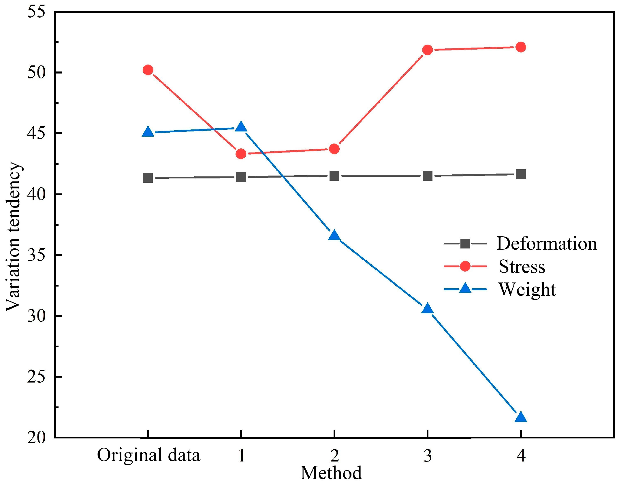
Table 6 shows the data changes for various characteristics of wheels with different optimization results. In order to reflect the changing trend in various characteristics more intuitively, Figure 12 is obtained (the vertical scale in the figure does not represent the real value but only represents the changing trend).
Figure 12 shows that the wheel’s deformation trend line is largely straight, with a modest overall change trend. The wheel’s stress trend line decreases and then increases, with a greater degree of decrease than increase, and the final increase in stress is not obvious. The weight shift of the inner rim indicates a decreasing tendency overall, and the difference is noticeable. It can be seen that the structural change in the inner rim has little influence on the overall deformation and stress of the wheel but has a great influence on its own weight change. By comparing the changing trends of various characteristics, the inner rim structure of method 4 can be preliminarily selected as the best scheme after optimization.
On the basis of a comparative analysis of static results, it is necessary to further complete the modal analysis and comparison of the optimized structures to finally determine the optimal structure of the inner rim. The comparative results of the free modal analysis of the inner rim are shown in Figure 13.
As can be seen in Figure 13, the free modal frequencies of each order of the optimized inner rim all exceed the corresponding value of the original structure, indicating that the overall anti-vibration ability of the inner rim has been strengthened after structural optimization. In addition, methods 1 and 2 maintain a similar change trend, while methods 3 and 4 maintain a similar change trend, and the numerical increase trend of methods 1 and 2 is more obvious than methods 3 and 4. Among them, the different diameters of the two support rings of methods 1 and 2 and methods 3 and 4 directly affect the resonance frequency of the inner rim, but the influence of the aperture change in large and small holes on its resonance frequency is not obvious enough, which shows that the optimization factors that effectively affect the resonance frequency of the inner rim are the added middle support ring and the inner support ring. Although the optimized structure of the inner rim using methods 1 and 2 can effectively improve its anti-vibration ability, the overall structural lightweight effect is not obvious; in contrast, the optimized structure with methods 3 and 4 cannot achieve the anti-vibration ability of methods 1 and 2, but it keeps the strengthening trend compared with the original structure, and the structural lightweight effect is obvious. Therefore, the static and modal results of the optimized structure of the inner rim are comprehensively analyzed, and the optimized result of method 4 is finally selected as the best optimization scheme for the inner rim.
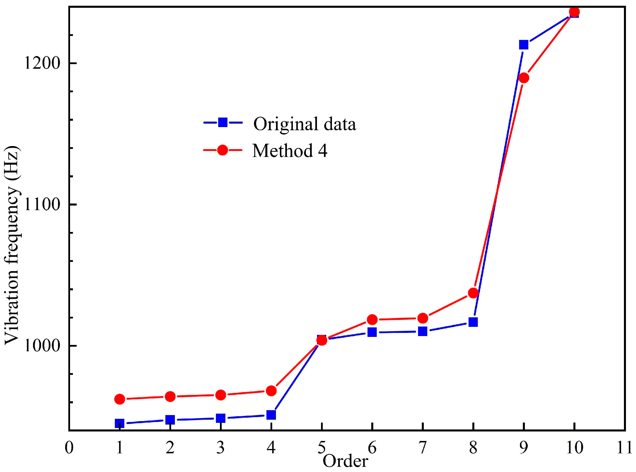
In addition, the results of the constraint modal before and after the optimization of the inner rim are compared, as shown in Figure 14. The inner rim adopts the optimization structure of method 4, and the constraint modal under real working conditions also shows an improvement trend compared with the original constraint modal. The optimized first-order constrained modal frequency is 962.2 Hz, which is obviously higher than the original first-order constrained modal frequency of 944.88 Hz. This further shows that the optimized structure of the inner rim with method 4 can reduce the weight as much as possible and improve the vibration resistance of the structure, and the optimization result is ideal, which meets the requirements of optimal design.

4.2. Outer Rim

The static analysis and verification method of the outer rim is the same as that of the inner rim. Under the condition of a 45 T design load, the original unoptimized outer rim is replaced by the above six optimized outer rims, and the other structural models and simulation parameter settings remain unchanged. The comparison results are shown in Table 7.
The “Original data” in Table 7 represent the results before optimization, and “1~6” represents the results after optimization. By comparing the data in Table 7, it can be seen that the deformation results of the optimized outer rim structure are obviously different under the same load conditions, and the overall trend keeps increasing with the reduction in the weight of the outer rim, indicating that structural changes in the outer rim have a certain influence on the deformation of the whole wheel, but the total deformation is smaller than the overall size of the wheel, so it can be ignored. As for the stress response caused by vertical loads, it can be clearly seen from the data that the stress response caused by different structures is quite different and keeps increasing with respect to weight reduction in the outer rim. When the outer rim adopts the structure of method 4, the maximum stress is 340.6 MPa, which is close to the yield limit of the Q345 low-alloy steel of 345 MPa, indicating that the optimized structure of the outer rim is not safe enough, although the weight is reduced. The data show that the weight of the outer rim before optimization is 1746 kg, and the weight after optimization is gradually decreasing. In method 6, the minimum weight is 1588.9 kg, which is 157.1 kg lower than that before optimization.
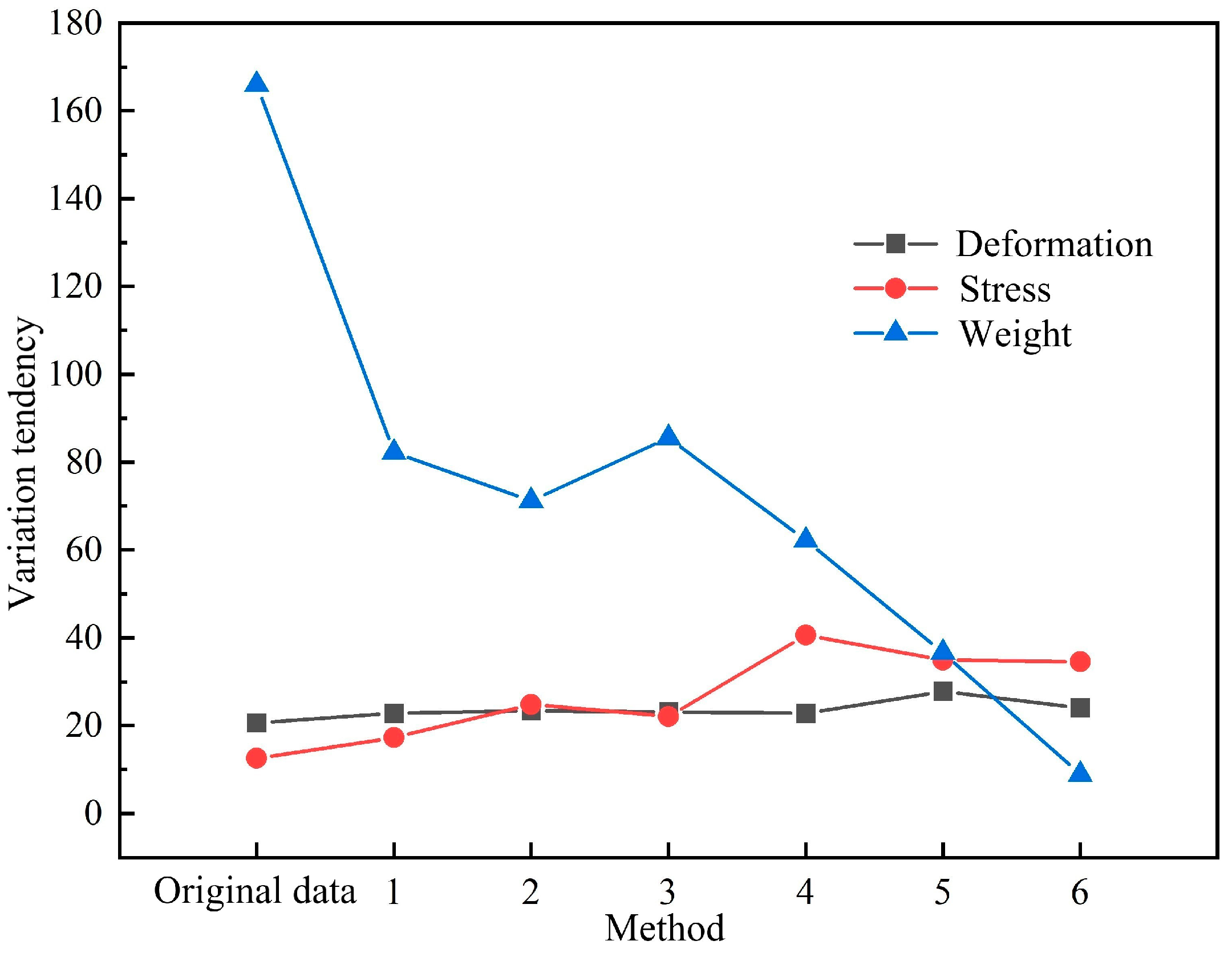
In order to reflect the changing trend of the characteristics of the wheel and the outer rim more intuitively, Figure 15 is obtained (the vertical scale in the figure does not represent the real value but only represents the changing trend).
As can be seen from in 15, the deformation trend line caused by the structural change in the outer rim generally exhibits a wavy upward trend, but the upward trend is not obvious. The stress trend line keeps an overall upward trend, with a local low point in method 3, which is higher than that in method 1, and then rises to the highest point in method 4; then, it slowly decreases, but the value in method 6 is still higher than that in method 3. Overall, the weight of the outer rim maintained a significant downward trend, with a local high point in method 3, which was higher than that in method 1, and then continued to decrease. From the trend chart, it can be seen that the optimal structure of the outer rim can be selected not only by the weight factor but also by the stress factor. Among the six optimized structures of the outer rim, methods 4, 5, and 6 are not adopted, although the weight is reduced more, stress is increased more, and wheel safety is decreased. Among methods 1, 2, and 3, method 2 results in more weight loss but greater stress, so it is also rejected. The remaining method 1 exhibits more weight loss and less stress increase than method 3, which basically meets the optimization requirements. Therefore, method 1 is initially selected as the best optimization scheme for the optimization structure of the outer rim.
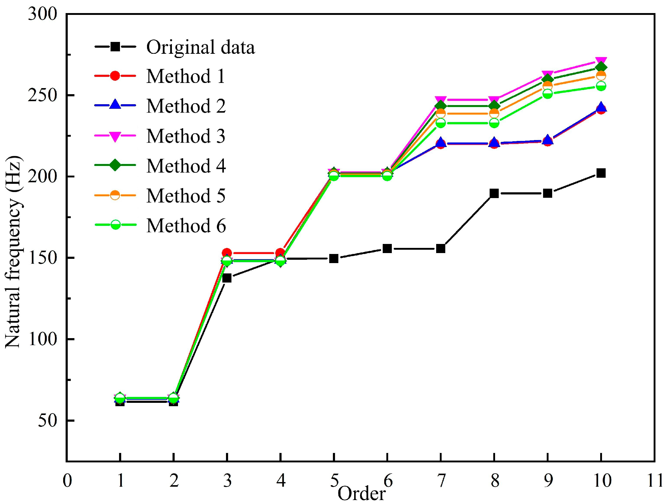
After the comparative analysis of the static results, the model’s analysis and the comparison of the optimized structures are further completed to finally determine the optimal structure of the outer rim. The comparative results of the free modal analysis of the outer rim are shown in Figure 16.
As can be seen in Figure 16, the free modal frequencies of the optimized outer rim structure are always higher than the corresponding frequency of the original structure, which shows that the anti-vibration ability of the outer rim has been improved after structural optimization. In the figure, the frequency trend lines of methods 1 and 2 are similar, but the frequency trend lines of methods 3, 4, 5, and 6 are quite different from methods 1 and 2 from the seventh order, and the four methods exhibit similar trends with small differences. Because the ribbed plate’s bottom length in methods 1 and 2 is 100 mm and that of methods 3, 4, 5, and 6 is 150 mm, the two trend lines differ significantly from the seventh order, indicating that changing the ribbed plate’s bottom length has a clear influence on the model. The trend lines for the first six orders of the six methods are essentially the same, but the six methods are mostly separated into two types of support plate through holes: 130 mm and 150 mm. This indicates that the model is not significantly affected by changes in the support plate through holes. Methods 3, 4, 5, and 6 have through hole sizes of 100 mm, 110 mm, 120 mm, and 130 mm, respectively. Hence, the trend lines of the four methods varied slightly but followed a similar trend from the seventh order. This demonstrates that changing the diameter of the through hole has an effect on the model. To summarize, the ribbed plate can significantly improve the anti-vibration ability of the outer rim, the support plate hole can reduce the weight of the outer rim, and the main through hole has two functions that meet the initial optimization design requirements. After a comprehensive analysis of the model’s comparison results and the static comparison results mentioned above, the optimization result of method 1 is finally selected as the best optimization scheme for the outer rim.
Subsequently, the results of the constraint modal of the outer rim before and after optimization are compared, as shown in Figure 17. The outer rim adopts the optimization structure of method 1, and the constraint modal under real working conditions also shows an improvement trend compared to the original constraint modal. The optimized first-order constrained modal frequency is 238.07 Hz, which is significantly higher than the original first-order constrained modal frequency of 131.23 Hz. This shows that the minimum resonance frequency of the outer rim has greatly exceeded the excitation response frequency of about 20–110 Hz after structural optimization design, and the outer rim has greatly improved the overall anti-vibration ability while realizing lightweight structures. The optimization result is ideal and meets the requirements of optimization design.

4.3. Whole Wheel

The structural optimization design of the wheel is mainly carried out around the inner rim and the outer rim. After topology optimization analysis and structural optimization design, the final optimization scheme is obtained: The inner rim adopts the optimization structure of method 4, and the weight is reduced by 23.43 kg. The outer rim adopts the optimization structure of method 1, and the weight is reduced by 83.8 kg. The whole wheel was reduced from 3686 kg in the initial design to 3578.8 kg after optimization, and the overall weight was reduced by 107.2 kg.
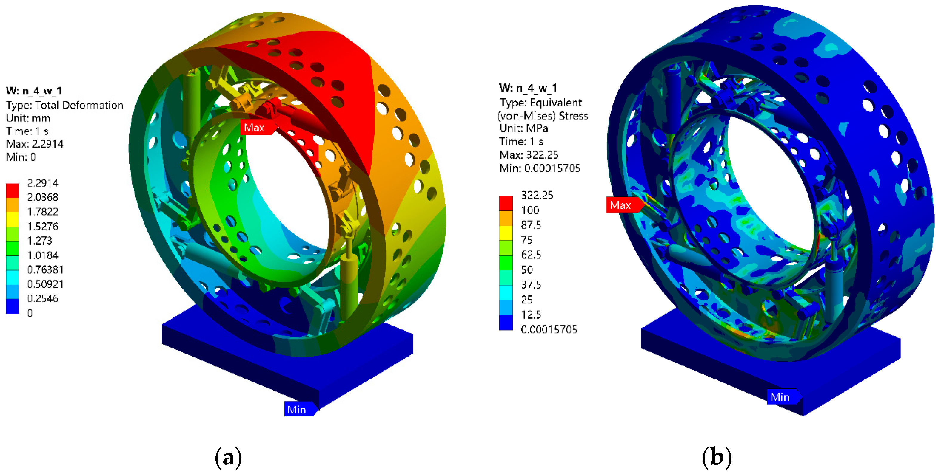
Subsequently, the optimized wheel is further verified via static analysis, and the analysis results are shown in Figure 18.
Figure 18 shows that the maximum deformation of the optimized wheel is 2.2914 mm under the condition of applying a 45 T vertical load, which is 0.2248 mm higher than the original 2.0666 mm. The maximum equivalent stress is 322.25 MPa, which is 9.7 MPa higher than 312.55 MPa before optimization. The reason is that when only one of the optimized structures of the inner rim and the outer rim is replaced for verification, the stress results are improved. For example, when only the inner rim is changed to the optimized structure of method 4, the stress result is 313.02 MPa, and when only the outer rim is changed to the optimized structure of method 1, the stress result is 317.25 MPa, which is higher than the original results. It can be inferred that the reasonable lightweight operation of the structure may lead to an improvement in its stress results. Although the wheel studied in this paper also has this kind of situation, it does not improve much, and the stress result of the wheel in this state is higher than that in the real working condition, so the final optimization scheme selected still has enough structural strength to meet the actual use requirements of the wheel.

5. Conclusions

In this paper, the topology optimization analysis and structural improvement design of the inner rim and outer rim are carried out. Firstly, the topology optimization analysis is completed according to the static analysis results of the two rims, and the reasonable and applicable topology analysis results are selected. Then, the optimization improvement scheme is preliminarily determined based on the modal analysis results of the two rims in the previous period, and several optimized structures to be verified are obtained by changing local detailed parameters. Secondly, static and modal simulation analyses and the verification of several optimized structures of the two are completed, and finally, the best optimized structures of the inner rim and the outer rim are determined; that is, the optimized structure of method 4 is adopted for the inner rim, and the optimized structure of method 1 is adopted for the outer rim. The overall weight of the wheel is reduced by 107.2 kg. Finally, the final optimized and improved structure of the two parts is assembled back onto the whole wheel to complete the final verification. Under the condition of applying a 45 T vertical load, the maximum deformation of the wheel is 2.2914 mm, and the maximum equivalent stress is 322.25 MPa. The optimized structure of the two parts meets the requirements of the real working conditions of the wheel, and the optimized result is reasonable.
In addition, it should be noted that according to the design requirements of the wheel, the outer diameter of the outer rim is 2290 mm, and the outer diameter of the inner rim is 1250 mm (as can be observed in Table 1), which far exceeds the conventional size of ordinary wheels. With the existing conditions and equipment in the laboratory, it is difficult to obtain the real wheel and complete the real verification experiment. The work that can be carried out at present is limited to computer simulation experiments, and the authenticity of the results has yet to be verified. The verification of the real wheel will be carried out when conditions are met in the future.

Author Contributions

Conceptualization, X.M., P.L. and X.S.; investigation, X.M., P.L. and X.S.; writing—original draft preparation, X.M.; writing—review and editing, X.F., P.L. and X.S. All authors have read and agreed to the published version of the manuscript.

Funding

This research received no external funding.

Data Availability Statement

The datasets used or analyzed during the current study are available from the corresponding author upon reasonable request.

Acknowledgments

We thank Ming Yao, Anning Wang, and Yanfei Li for their suggestions and recommendations.

Conflicts of Interest

Authors P.L. and X.S. were employed by Qingdao Shuangxing Equipment Manufacturing Co., Ltd. The remaining authors declare that the research was conducted in the absence of any commercial or financial relationships that could be construed as a potential conflict of interest.

References

  1. Gu, X.; Yang, K.; Wu, M.; Zhang, Y.; Zhu, J.; Zhang, W. Integrated optimization design of smart morphing wing for accurate shape control. Chin. J. Aeronaut. 2021, 34, 135–147. [Google Scholar] [CrossRef]
  2. De Gaspari, A. Multiobjective Optimization for the Aero-Structural Design of Adaptive Compliant Wing Devices. Appl. Sci. 2020, 10, 6380. [Google Scholar] [CrossRef]
  3. Baldzhiev, R.S.; Alekseyev, A.A.; Azarov, A.V. Topology optimization of the lattice payload adapter for carrier rocket. IOP Conf. Ser. Mater. Sci. Eng. 2019, 683, 012061. [Google Scholar] [CrossRef]
  4. Borda, F.; La Rosa, A.D.; Filice, L.; Gagliardi, F. Environmental impact of process constrained topology optimization design on automotive component’ life. Int. J. Mater. Form. 2023, 16, 48. [Google Scholar] [CrossRef]
  5. Tuncer, G.; Mansouri, D.; Şendur, P. The effect of spotwelds and structural adhesives on static and dynamic characteristics of vehicle body design. Proc. Inst. Mech. Eng. Part D-J. Automob. Eng. 2021, 235, 3207–3219. [Google Scholar] [CrossRef]
  6. Yu, Y.; Wei, M.; Cui, Y.; Sun, B.; Yu, Z.; Xu, Q.; Wu, Y. Reliability-based topology-topography optimization for ship bulkhead structures considering multi-failure modes. Ocean. Eng. 2024, 293, 116681. [Google Scholar] [CrossRef]
  7. Garbatov, Y.; Huang, Y.C. Multi-objective eliability-based design of ship structures subjected to fatigue damage and compressive collapse. J. Offshore Mech. Arct. Eng. 2020, 142, 051701. [Google Scholar] [CrossRef]
  8. Golecki, T.; Gomez, F.; Carrion, J.; Spencer, B.F., Jr. Topology optimization of high-speed rail bridges considering passenger comfort. Struct. Multidiscip. Optim. 2023, 66, 215. [Google Scholar] [CrossRef]
  9. Cascino, A.; Meli, E.; Rindi, A. A New Strategy for Railway Bogie Frame Designing Combining Structural–Topological Optimization and Sensitivity Analysis. Vehicles 2024, 6, 651–665. [Google Scholar] [CrossRef]
  10. Kim, J.; Kim, J.J.; Jang, I.G. Integrated topology and shape optimization of the five-spoke steel wheel to improve the natural frequency. Struct. Multidiscip. Optim. 2022, 65, 78. [Google Scholar] [CrossRef]
  11. Zhang, Y.; Shan, Y.; Liu, X.; He, T. An integrated multi-objective topology optimization method for automobile wheels made of lightweight materials. Struct. Multidiscip. Optim. 2021, 64, 1585–1605. [Google Scholar] [CrossRef]
  12. Chu, D.; Bai, W.; He, Y.; Ye, M.; Li, J. Research on lightweight technology of new carbon fiber wheel hub structure. IOP Conf. Ser. Earth Environ. Sci. 2021, 632, 052071. [Google Scholar] [CrossRef]
  13. GB/T 5909-2009; Performance Requirements and Test Methods of Commercial Vehicles Wheels. General Administration of Quality Supervision, Inspection and Quarantine of the People’s Republic of China, Standardization Administration of the People’s Republic of China: Beijing, China, 2009.
  14. Wang, D.; Zhang, S.; Xu, W. Multi-objective optimization design of wheel based on the performance of 13° and 90° impact tests. Int. J. Crashworthiness 2019, 24, 336–361. [Google Scholar] [CrossRef]
  15. Jang, I.G.; Sung, Y.H.; Yoo, E.J.; Kwak, B.M. Pattern design of a non-pneumatic tyre for stiffness using topology optimization. Eng. Optim. 2021, 24, 336–361. [Google Scholar] [CrossRef]
  16. Muller, P.; Mthembu, L. Topological Optimization of Mining Vehicle Tyre. Eng. Headw. 2024, 6706, 45–63. [Google Scholar] [CrossRef]
  17. Karthikeyan, K.; Kishore, R.; Jeeva, K.; Kumar, H.; Kannan, R.S. Topology optimization of an ATV wheel hub. J. Phys. Conf. Ser. 2021, 2027, 012022. [Google Scholar] [CrossRef]
  18. Zhang, S.; Lu, D.; Li, R.; Xu, L.; Jiang, H.; Cao, Y.; Xu, W. Fatigue life optimization and lightweight design of wheel based on entropy weight grey relation analysis and modified NSGA-II. Adv. Mech. Eng. 2023, 15, 16878132231189119. [Google Scholar] [CrossRef]
  19. Zhang, T.; Chen, X.; Zhang, L.; Song, J.; Sun, W. Lightweight design of hub under three working conditions based on Topological optimization. J. Phys. Conf. Ser. 2022, 2338, 012074. [Google Scholar] [CrossRef]
  20. Jasoliya, D.; Shah, D.B.; Lakdawala, A.M. Topological optimization of wheel assembly components for all terrain vehicles. Mater. Today: Proc. 2022, 59 Pt 1, 878–883. [Google Scholar] [CrossRef]
  21. Kemeny, Z. Mine Material Processing Apparatus Including Gas Spring Wheel Assemblies and Related Methods. AU2022238788A1, 28 September 2023. [Google Scholar]
  22. Bendsoe, M.P.; Kikuchi, N. Generating optimal topologies instructural design using a homogenization method. Appl. Mech. Eng. 1988, 71, 197–224. [Google Scholar] [CrossRef]
  23. Rozvany, N.I.G. A critical review of established methods of structural topology optimization. Struct. Multidisc. Optim. 2009, 37, 217–237. [Google Scholar] [CrossRef]
  24. Costa, G.; Montemurro, M.; Pailhès, J. Minimum length scale control in a NURBS-based SIMP method. Comput. Methods Appl. Mech. Eng. 2019, 354, 963–989. [Google Scholar] [CrossRef]
  25. Sethian, J.A.; Wiegmann, A. Structural boundary design vialevel set and immersed interface methods. J. Comput. Phys. 2000, 163, 489–528. [Google Scholar] [CrossRef]
  26. Wang, Y.M.; Wang, X.; Guo, D. A level set method for structural topology optimization. Comput. Methods Appl. Mech. Eng. 2003, 192, 227–246. [Google Scholar] [CrossRef]
  27. Xie, Y.M.; Steven, G.P. A simple evolutionary procedure for structural optimization. Comput. Struct. 1993, 49, 885–896. [Google Scholar] [CrossRef]
  28. Huang, X.; Xie, Y.M. Convergent and mesh-independent solutions for the bi-directional evolutionary structural optimization method. Finite Elem. Anal. Des. 2007, 43, 1039–1049. [Google Scholar] [CrossRef]
  29. Guo, X.; Zhang, W.; Zhong, W. Doing topology optimization explicitly and geometrically-a new moving morphable components based framework. J. Appl. Mech. 2014, 81, 081009. [Google Scholar] [CrossRef]
  30. Zhang, W.; Li, D.; Yuan, J.; Song, J.; Guo, X. A new three-dimensional topology optimization method based on moving morphable components (MMCs). Comput. Mech. 2017, 59, 647–665. [Google Scholar] [CrossRef]
  31. Zhang, W.; Li, D.; Kang, P.; Guo, X.; Youn, S.K. Explicit topology optimization using IGA-based moving morphable void (MMV) approach. Comput. Methods Appl. Mech. Eng. 2020, 360, 112685. [Google Scholar] [CrossRef]
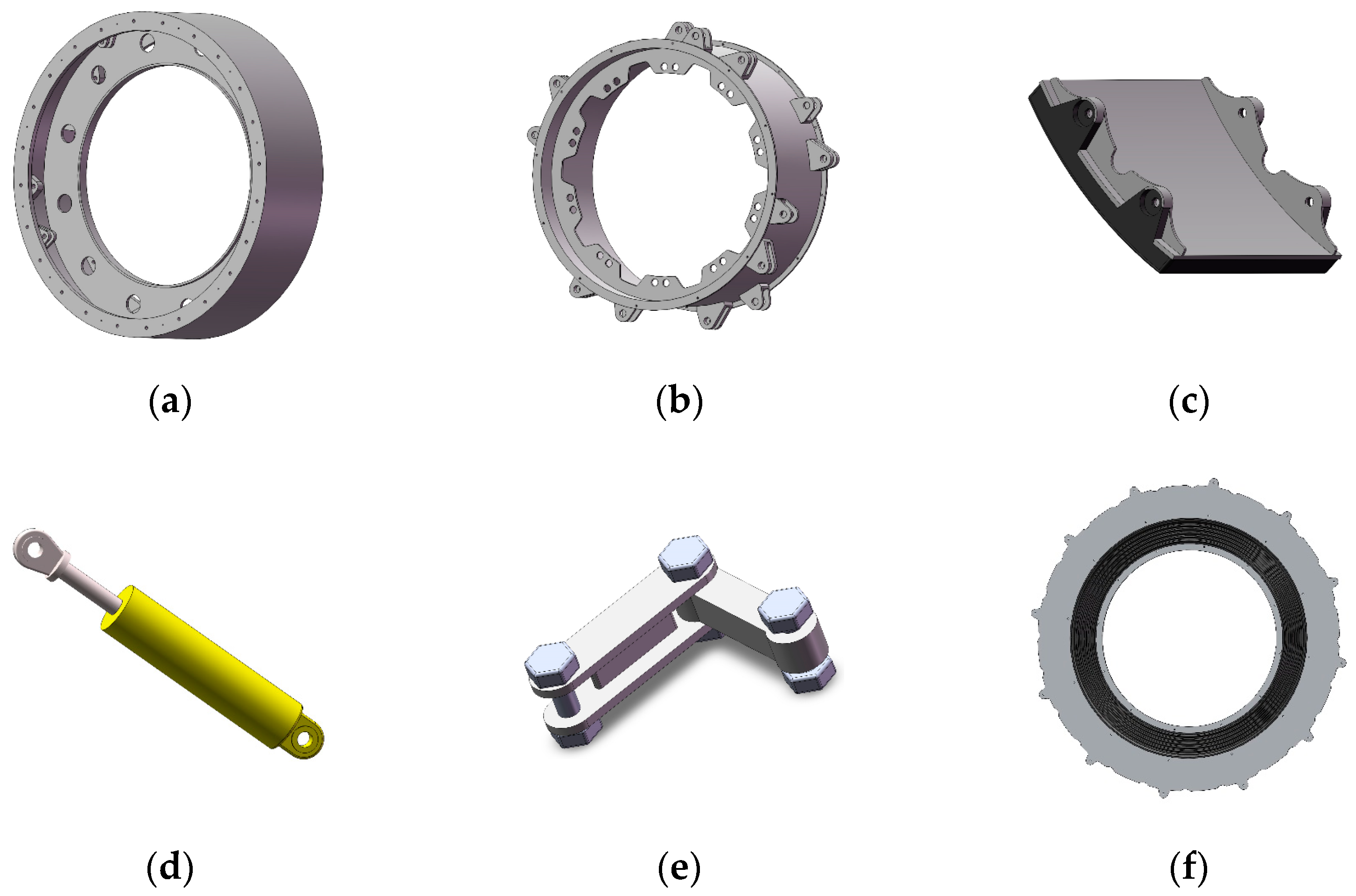
Figure 1. Structure of wheel parts. (a) Outer rim; (b) inner rim; (c) non-pneumatic tire skin; (d) pneumatic spring; (e) transverse brake; (f) dust shield.
Machines 12 00488 g001
Figure 2. Air suspension mechanical-vibration-reduction wheel.
Machines 12 00488 g002
Figure 3. Topology optimization analysis flowchart.
Machines 12 00488 g003
Figure 4. Supporting reaction force on the inner rim.
Machines 12 00488 g004
Figure 5. Optimization and exclusion area of the inner rim.
Machines 12 00488 g005
Figure 6. Topology optimization results of the inner rim. (a) Result 1; (b) result 2; (c) result 3.
Machines 12 00488 g006
Figure 7. Optimization scheme of the inner rim.
Machines 12 00488 g007
Figure 8. Supporting reaction force on the outer rim.
Machines 12 00488 g008
Figure 9. Optimization and exclusion area of the outer rim.
Machines 12 00488 g009
Figure 10. Topology optimization results of the outer rim. (a) result 1; (b) result 2; (c) result 3.
Machines 12 00488 g010
Figure 11. Optimization scheme of the outer rim.
Machines 12 00488 g011
Figure 12. Trend diagram of wheel characteristics change.
Machines 12 00488 g012
Figure 13. Free modal comparison of the inner rim before and after optimization.
Machines 12 00488 g013
Figure 14. Comparison of constraint modal of the inner rim before and after optimization.
Machines 12 00488 g014
Figure 15. Trend diagram of wheel characteristic change.
Machines 12 00488 g015
Figure 16. Free modal comparison of the outer rim before and after optimization.
Machines 12 00488 g016
Figure 17. Comparison of the constraint modal of the outer rim before and after optimization.
Machines 12 00488 g017
Figure 18. Static analysis results of the optimized wheel. (a) Deformation result; (b) stress result.
Machines 12 00488 g018
Table 1. Important dimensions of the wheel.
Wheel Width (mm)Wheel Outer Diameter (mm)Outer Diameter of Outer Rim (mm)Inner Diameter of Outer Rim (mm)Inner Diameter of Support Plate (mm)Outer Diameter of Inner Rim (mm)Inner Diameter of Inner Rim (mm)
712242022902240155012501212
Table 2. Supporting reaction force on each lug of the inner rim. (a) Supporting reaction force of No.1~No.8 lugs; (b) supporting reaction force of No.9~No.16 lugs.
(a)
Coordinate1
(N)
2
(N)
3
(N)
4
(N)
5
(N)
6
(N)
7
(N)
8
(N)
X−1820.1−11,844−88,780−4061.6−1622−16,348−75,930−10,919
Y−605.03587.08−510.942578.8210.28−2499528.21−683.07
Z−24,413−236.28−1273.31487.89269.9−6646.2−2043.78482.4
(b)
Coordinate9
(N)
10
(N)
11
(N)
12
(N)
13
(N)
14
(N)
15
(N)
16
(N)
X−66,662−7296.5−35,062−15,686−38,439−3652.1−46,688−16,188
Y569.511167.4310.871335.9−321.1753.75−573.58−2849.2
Z60,605−1185.3−35,2975016.434,637−1589.2−46,8161.4433
Table 3. Parameter settings of improved results.
MethodLarge Hole (mm)Small Hole (mm)Middle Support Ring (mm)Inner Support Ring (mm)
1805013001105
2906013001105
3805012701160
4906012701160
Table 4. Supporting reaction force on each lug of the outer rim. (a) Supporting reaction force of No.1~No.8 lugs; (b) supporting reaction force of No.9~No.16 lugs.
(a)
Coordinate1
(N)
2
(N)
3
(N)
4
(N)
5
(N)
6
(N)
7
(N)
8
(N)
X88,78011,8441820.110,91975,93016,34816224061.6
Y510.94−587.08605.03683.07−528.212499−210.28−2578.8
Z1273.3236.2824,413−8482.42043.76646.2−9269.9−1487.8
(b)
Coordinate9
(N)
10
(N)
11
(N)
12
(N)
13
(N)
14
(N)
15
(N)
16
(N)
X66,66216,18846,6883652.138,43915,68635,0627296.5
Y−569.512849.2573.58−753.75321.1−1335.9−310.87−1167.4
Z−60,605−1.443446,8161589.2−34,637−5016.435,2971185.3
Table 5. Parameter settings of improved results.
MethodSupport Plate Hole (mm)Ribbed Plate
(mm)
Circular Hole
(mm)
1130100100
2150100100
3150150100
4150150110
5150150120
6150150130
Table 6. Static analysis and comparison of optimization results of the inner rim.
MethodDeformation
(mm)
Stress
(MPa)
Weight
(kg)
Original data2.0666312.55445.05
12.0702310.83445.45
22.0759310.93436.54
32.0757312.96430.53
42.0825313.02421.62
Table 7. Static analysis and comparison of optimization results of the outer rim.
MethodDeformation
(mm)
Stress
(MPa)
Weight
(kg)
Original data2.0666312.551746
12.2793317.251662.2
22.3347324.861651.2
32.3074322.091665.5
42.2812340.61642.2
52.7762334.941616.6
62.4027334.541588.9
Disclaimer/Publisher’s Note: The statements, opinions and data contained in all publications are solely those of the individual author(s) and contributor(s) and not of MDPI and/or the editor(s). MDPI and/or the editor(s) disclaim responsibility for any injury to people or property resulting from any ideas, methods, instructions or products referred to in the content.