Review

Friction Stir Channeling in Heat Sink Applications: Innovative Manufacturing Approaches and Performance Evaluation

by
Sooraj Patel
1,2 and
Amit Arora
1,*
1
Advanced Materials Processing Research Group, Department of Materials Engineering, Indian Institute of Technology Gandhinagar, Gandhinagar 382355, Gujarat, India
2
School of Aerospace and Mechanical Engineering, The University of Oklahoma, Norman, OK 73019, USA
*
Author to whom correspondence should be addressed.
Machines 2024, 12(7), 494; https://doi.org/10.3390/machines12070494 (registering DOI)
Submission received: 2 June 2024 / Revised: 7 July 2024 / Accepted: 19 July 2024 / Published: 22 July 2024

Abstract

:
The fabrication of compact heat exchangers with precisely designed micro- and mini-channels is crucial for enhancing the efficiency of thermal management systems. Friction stir channeling (FSC) emerges as a cost-effective advanced manufacturing process to create complex integral channels, offering channel shape and size flexibility. This review article highlights the pivotal role of processing parameters in channel formation and maintaining their integrity, necessitating a comprehensive understanding of material flow dynamics. A rigorous assessment has been conducted on the channel under mechanical stresses, including tension, bending, and fatigue. The paper emphasizes the potential of FSC to revolutionize heat sink applications by exploring the fundamental concepts, governing parameters, ongoing enhancements in tool design, microstructural and mechanical properties, and heat transfer performance.

1. Introduction

Electric vehicles have proven to be an energy-efficient alternative in the revolutionary market to solve greenhouse gas emissions [1]. In electric vehicles, a significant number of battery cells are required to obtain mileage equivalent to gasoline-powered vehicles. According to recent data [2], the Tesla Model S Plaid utilizes 7920 battery cells to attain a range of 645 km. Thermal losses occur as a result of internal resistance and electrochemical reactions. These thermal losses contribute to increasing the temperature of EV battery cells during charging and discharging, particularly in lithium-ion batteries [3]. The optimum temperature of lithium-ion battery cells should be in the range of 20–40 °C [4]. A high temperature of EV batteries reduces the acceleration response in the earlier stage, leading to a reduced life span and causing irreversible damage to the batteries [5]. Another significant risk to the EV battery system is thermal runaway. Thermal runaway can occur when heat is not adequately dissipated from the battery cells, resulting in temperatures exceeding 80 °C. This phenomenon can lead to the release of hazardous gases, potentially causing fires and, in some instances, explosions [4,6]. The temperature difference in each module creates an uneven temperature distribution, leading to an electrically unbalanced battery pack that ultimately reduces battery performance [7]. The heat dissipation of EV battery cells is improved by providing external cooling [8,9]. It can be provided by a heat exchanger in the form of heat sinks.
Complex tube paths need to be incorporated to provide sufficient cooling for maintaining a low-temperature difference between modules. Researchers have analyzed heat transfer for the different cooling channel paths, such as serpentine profiles [10] and parallel cooling pipes [11]. A serpentine profile showed a maximum temperature drop and a small temperature difference over other profiles using numerical simulation [9]. CFD analysis predicted improved efficiency of mini-channel cooling plates in the streamlined path [12]. Compact heat exchangers can be manufactured using chemical etching, electron beam machining, micro-milling, precision machining, wire-cut electro-discharge machining, laser micro-machining, and selective laser melting [13,14]. These techniques are very expensive and have a low machining rate. The subsidiary steps are also involved in making an integral channel, such as covering the open channels using a separate material sheet. It is challenging to obtain a leakage-free joint at the cover-plate interface. Additive manufacturing, while capable of overcoming many limitations associated with traditional manufacturing methods [15,16,17], faces significant challenges in terms of cost competitiveness and mass-scale production. This makes it a less viable solution for fabricating heat sinks. Friction Stir Channeling (FSC) can be an alternative process to produce small-scale heat exchangers with a high cooling performance at low cost.
The FSC has garnered attention for its capability to fabricate channels, including intricate serpentine geometries. Prior studies have investigated various FSC concepts, utilizing diverse tools and process parameters for channel formation. However, a few instances in the literature are available [18] that offer a comprehensive and holistic overview of the FSC process and its applications. This review article aims to bridge this knowledge gap by providing a comprehensive overview of different FSC concepts, their associated process parameters, microstructural and mechanical properties, and the performance of channels in heat transfer applications. Furthermore, the article outlines the prospects and potential advancements in this technology, making it particularly relevant and valuable to researchers working in the field of complex heat sink fabrication for thermal management systems.
The mechanism of channel fabrication using the friction stir channeling process is explained in Chapter 2. The channels were fabricated using the threaded tool in the initial stages. Several modifications have been incorporated into the tool design to enhance the material flow. Chapter 3 discusses modifications to FSC concepts and tool design innovation. A channel is fabricated under the influence of heat and severe plastic deformations. Chapter 4 discusses the different microstructural regions that are formed in the channel surrounding it. The material flow is studied to optimize the processing conditions. The formation of the channel walls has also been analyzed to understand the detailed material flow mechanism. The processing parameters chapter (Chapter 5) discusses the influence of parameters such as traverse speed, tool rotation speed, tilt angle, and tool geometry on the channel shape, size, and integrity. The stresses induced during the FSC process influence mechanical properties such as hardness, tensile strength, and fatigue strength. The mechanical properties chapter (Chapter 6) analyzes the effect of processing parameters on the channel strength and the fracture reasons under mechanical loading. The defects may occur in the friction sir channels due to insufficient material flow, the selection of inappropriate processing parameters, and/or the shoulder force. The possible defects and their causes are discussed in Chapter 7. The FSC process is aimed at heat sink applications. The performance of the channels to measure the heat transfer capacity is discussed in Chapter 8. The heat transfer performance is also compared with the milled channel.

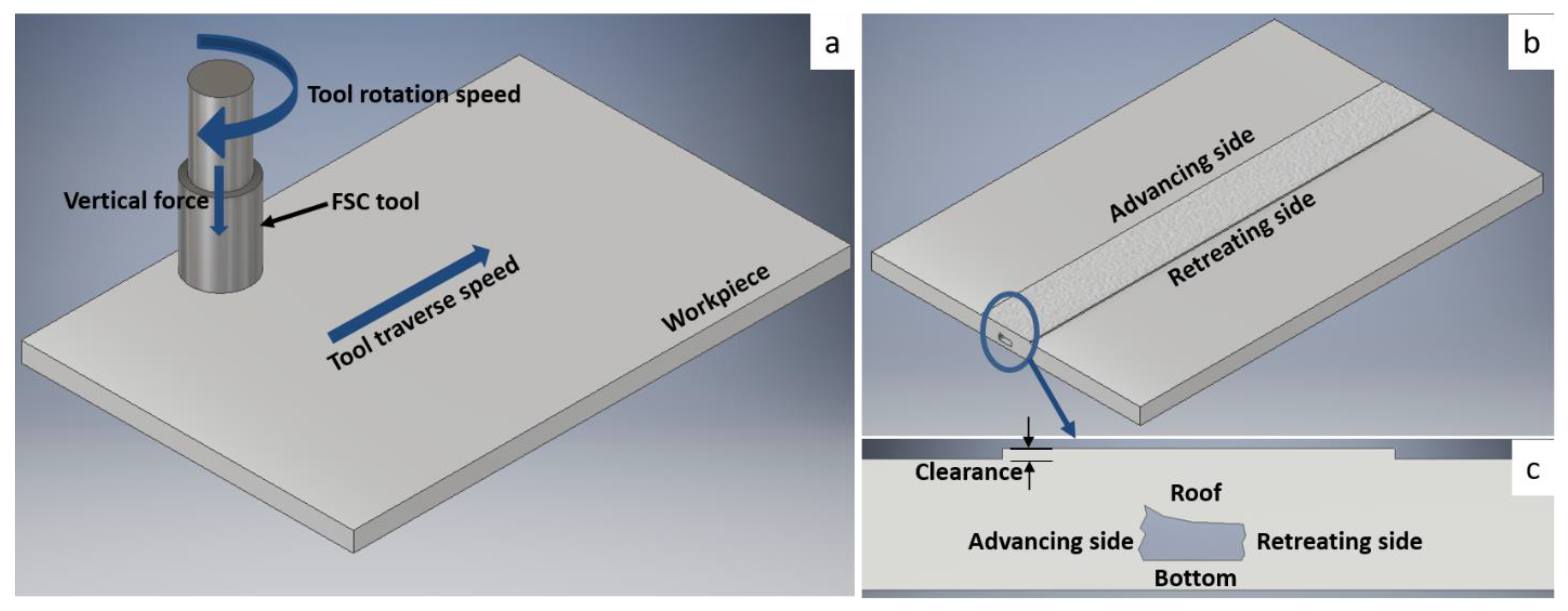
2. Friction Stir Channeling Process

FSC is an advanced extension of Friction Stir Welding (FSW), enabling the fabrication of integral channels along complex paths, including serpentine profiles. FSC demonstrates a substantially greater surface roughness, with a channel-roof roughness of 5.656 µm [19], in comparison to conventional machining techniques. The increased roughness, up to 20 times at the channel roof and 10 times at the bottom compared to milled channels, enhances the surface contact area for heat transfer [20]. A surface area density exceeding 700 m2/m3 can be achieved using FSC, making it highly effective for applications requiring efficient conformal heating and cooling [21].
FSC is a solid-state technique where the workpiece material is rotated and moved upward using a rotating tool. The concept of FSC is similar to FSW [22] except for the material flow. The schematic representation of the friction stir channeling process is shown in Figure 1. A tool rotates at a predetermined speed, and a vertical force is applied to plunge the tool pin into the workpiece. The tool is inserted until the required clearance is reached between the upper workpiece and the tool shoulder. Friction occurs at the interface between the tool pin and the workpiece, generating frictional heat. This heat softens the material in the tool-pin vicinity, initiating a stirring action driven by the tool’s rotation. Heat dissipation also occurs due to severe plastic deformation and the viscous flow of the material. However, as the material flow has visco-plastic behavior at a higher temperature, the frictional heat generation tends to be zero. During the FSC process, the material flow is described by the “third body region” concept [23], where the flow stresses are mechanically introduced above the recrystallization temperature [24].
Tool design is critical, as it determines the development of a continuous channel. A tool consists of three fundamental components: the pin, the shoulder, and the body. It must meet specific requirements, including (i) dissipation of heat generated by friction and severe plastic deformation of visco-plasticized material, (ii) guidance of material flow, and (iii) resistance to mechanical stresses.
The plasticized material is separated at the pin base during the FSC. This material is directed upwards towards the bottom of the shoulder. The threads on the tool pin are specifically designed to facilitate this upward material flow in conjunction with the rotational motion of the tool. The geometry of the tool pin ensures the upward movement of the stirred material. The pin threads control the vertical flow of material based on the rotation direction and the orientation of the threads. Left-handed threads with counterclockwise tool rotation, and right-handed threads with clockwise rotation, ensure the desired material flow. The tool-body dissipates the heat and bears the mechanical stresses involved during the channeling process. The extracted material moves upward, leaving behind a cavity, and deposits on the top of the workpiece underneath the shoulder. Therefore, the upper workpiece surface does not remain at the same level, as illustrated in Figure 1b,c). A series of cavities forms at the tool pin base as the tool advances in the transverse direction. Such cavities are considered channels when they make an integral path, as depicted in Figure 1b,c.
The internal surfaces of fabricated channels exhibit irregularities influenced by multiple factors, including the utilized FSC concept, the selected process parameters, and the geometry of the channeling path. The tool geometry and processing parameters, such as tool rotational speed, traverse speed, and tilt angle, are critical in determining the channel shape and size [21]. Channel formation is characterized in various processed regions, as illustrated in Figure 2. Tool rotation generates the stirred zone and forms the channel nugget (Regions A and B). Region C displays the channel cross-section, while Region D shows the unprocessed base material. The material deposited on the workpiece surface beneath the shoulder is depicted in Region E.
The FSC process provides flexibility to generate an internal cavity in the desired shape by traveling the tool on the workpiece surface. The provident feature of the FSC is to fabricate a closed channel in a complex geometric path, including a serpentine profile. However, channel integrity does not remain uniform throughout the pattern [21]. Several modifications in the material extraction have been carried out to fabricate channels with improved shape and size, along with uniformity on a curved path.

3. Advances in Friction Stir Channeling Concepts and Tool Design Innovations

The conventional FSC concept employs a tool featuring a cylindrical threaded pin and a flat tool shoulder. Figure 3 presents a schematic of the conventional FSC tool, which is analogous to the tool used in the Friction Stir Welding (FSW) process [25,26,27]. In this concept, a clearance is maintained between the tool shoulder and the workpiece, permitting the deposition of extracted material within this gap. The threaded pin promotes the upward flow of visco-plasticized material, while the shoulder applies a forging force through the deposited material to close the channel. This forging force reduces significantly with increasing clearance. Reduced shoulder force allows a greater amount of material to be extracted, resulting in larger channel sizes. The shape, size, and integrity can be controlled by adjusting the tool shoulder and workpiece surface gap [19,28]. However, excessive clearance can lead to channel defects, such as step defects or open channels on the Advancing Side (AS), due to less shoulder influence. Over time, various modifications have been implemented to enhance the material extraction process and fabricate channels with improved dimensional accuracy [18].
As a modification to the conventional tool design, a scroll is provided on the shoulder to promote material flow so that the extracted material does not deposit on the workpiece surface. A scroll crafted on the flat tool shoulder is shown in Figure 4. This scroll directs the extracted material to flow from the pin toward the shoulder periphery [29]. Here, the clearance between the workpiece and the tool shoulder is discarded as the plasticized material extracts in the form of self-detachable flashes. Figure 5 schematically compares the conventional FSC concept with the FSC without clearance, which includes a scroll on the tool shoulder. If the correct processing parameters are considered for channel fabrication, further surface finishing is not required as the processed surface remains at the same level [24,30]. In this FSC concept, the shoulder can provide maximum forging force as it is in contact with the workpiece surface.
The pitch and depth of cut of the tool pin threads significantly influence the amount of extracted material. A limited helix angle of threads may increase the upward material flow compared to the flow surrounding the tool pin. The scroll on the shoulder facilitates the extraction of material, while the remaining shoulder provides the forging force necessary to close the channel. Various tool pin geometries, featuring different thread and scroll angles, are depicted in Figure 6 [31]. Material extraction can be enhanced by providing multiple scrolls on the tool shoulder [32].
Friction stir channels are also fabricated using an unthreaded tool pin, where the upward material flow for channel formation is achieved by employing a tool-tilt angle [33]. This tilt angle is introduced in two ways: (i) incorporating an upward conical shape in the tool profile and (ii) physically tilting the conventional tool during the channeling process [34]. An upward conical pin (UCP) tool and a conventional tool with a straight cylindrical pin (SCP) tool are depicted in Figure 7a,b, respectively. The schematic representation of the tilt angle implementation using both tools is illustrated in Figure 8. The downward forging force for the physically tilted tool does not remain uniform throughout the shoulder surface. An inclination of 3° is found to be optimal for achieving a better shape and size of the channel. This inclination at the pin base facilitates the upward movement of the material. Significant variation in the upward material flow at the AS is observed for a minor change in the tool tilt angle [35]. Therefore, the tool tilt angle is critical in this FSC concept. The impact of the tool tilt angle on the FSC with an unthreaded tool pin is further discussed in Section 5.2.
The channel can also be formed using a stationary tool shoulder, which remains in contact with the workpiece surface. Figure 9a illustrates a schematic of material extraction through a stationary tool shoulder. A stationary tool shoulder significantly limits viscoplastic material flow in the nugget region. The tool design incorporates vents within the shoulder, directing the flow of extracted material into the shoulder and expelling it through these vents (Figure 9b). Figure 9c depicts a serpentine-shaped channel fabricated using this concept. As shown in Figure 9d, the extruded wire is produced through continuous material extraction from the vents. This wire can be utilized as feedstock for other manufacturing processes, such as wire-based additive manufacturing and conventional welding wires [36].
The Hybrid Friction Stir Channeling (HFSC) process enables simultaneous welding and channeling. The tool-pin configuration creates a unique material flow that forms both a joint and a channel in a single pass. Hence, it is possible to weld a channeling specimen with a dissimilar substrate. The key advantage of HFSC is to fabricate a composite heat sink structure of aluminum and copper for thermal management systems [37]. Tool-pin threads in opposite directions are illustrated in Figure 10a. The welding probe of the conical-shaped profile is incorporated at the tip of the channeling probe. The welding probe promotes downward material flow, whereas the channeling probe promotes the material to move upward for channel formation. The intermixing of materials using the welding probe results in a weld comparable to that achieved through the FSW. Various joint configurations, including butt, lap, and combined lap and butt joints, can be formed alongside the channels, as shown in Figure 10b. Diverse processing conditions enable the formation of a wide array of channel shapes, sizes, and integrities [38]. A summary of channel fabrication using different FSC concepts is provided in Table 1.

4. Formation of Integral Closed Channels

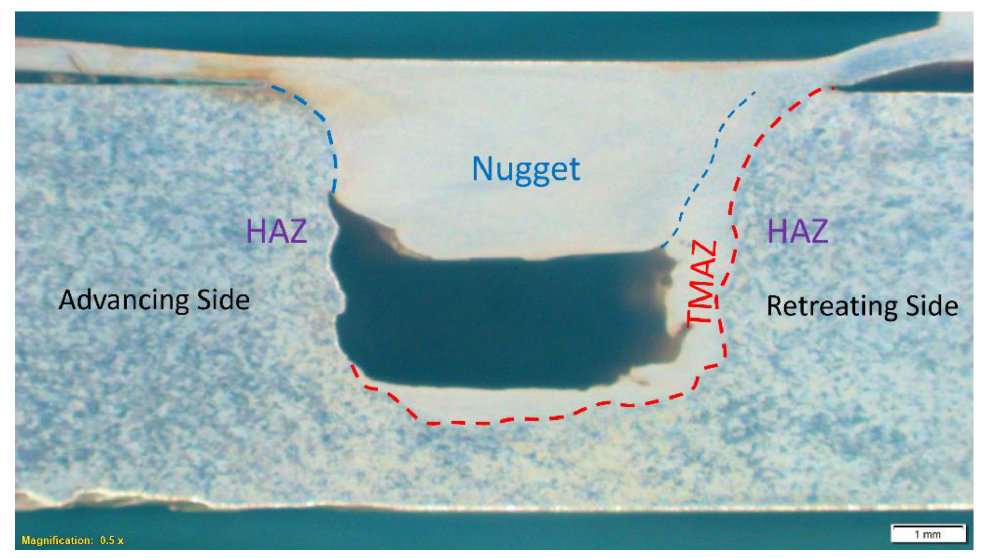
4.1. Formation of Nugget, TMAZ, and HAZ

Frictional heat is generated when a non-consumable rotating tool is inserted into the workpiece [39,40,41,42]. Severe plastic deformation occurs at a higher temperature during the FSC process, resulting in different regions in the substrate. These regions are (i) Nugget/Stir Zone (SZ) (ii) Thermo-Mechanically Affected Zone (TMAZ) (iii) Heat Affected Zone (HAZ) (iv) Channel and (v) Base Metal (BM). The schematic representation of the regions formed during the FSC is shown in Figure 11.
The nugget formed during the FSC process is shown in Figure 12a. Severe plastic deformation occurs in the stir zone due to material flow across the tool pin. Heat is generated due to friction and visco-plastic deformation [43]. Therefore, the nugget/stir zone is profoundly affected by the tool rotation. A peak temperature exceeds 0.6 Tmax [44,45,46] in the nugget zone during the FSW concerning the processing parameters. Climb and cross-slip are easy to occur for the higher stacking fault energy materials such as aluminum. Severe plastic deformation induces dynamic recovery, which is subsequently followed by dynamic recrystallization [25,47,48,49,50]. As a result, very fine equiaxed grains are formed in the stir zone, as shown in Figure 12b.
The zone just next to the nugget is considered a Thermo-Mechanically Affected Zone (TMAZ) [51,52,53]. The material undergoes less plastic strain in this region. The temperature is also lower compared to the nugget. However, it is above the recrystallization temperature. The distorted grains and material flow are still identified, along with the tool rotation. The available heat and plastic deformation are insufficient to form well-developed, fine-equiaxed grains. The material is influenced only by the thermal effects next to the TMAZ. The material does not undergo any plastic deformation in this region. Such a region is considered a heat-affected zone. The remaining area is not affected by the thermal cycle, or any strain recognized as the base material.
The material extracted from the AS flows in two ways. (i) A certain portion of the material moves upward along with the tool geometry. This material deposits on the workpiece surface or is removed as detached flashes. (ii) The remaining material rotates from the leading edge to the RS. It deposits at the RS or in the cavity formed due to the forward motion of the tool. A distinct interface between SZ and TMAZ can be identified at the AS, as shown in Figure 12c, as no material deposits back to the AS [54]. On the other hand, the microstructure from the nugget to the Retreating Side(RS) changes smoothly, as shown in Figure 12d [55]. Unlike the AS, a sharp distinction cannot be identified at the RS.
Figure 12. (a) Cross-section of friction stir channel (b) Microstructure in nugget (c) TMAZ at AS (d) TMAZ at RS. Reprinted from Ref. [55] with permission from Elsevier.
Machines 12 00494 g012

4.2. Effect of Material Flow on Channel Formation

Material flow plays a key role in the FSC process as it governs the channel shape and size. Tool pin geometry and processing parameters control the flow during the FSC. The upward material flow is attributed to the tool feathers or the tool-pin thread and tool rotation directions. This feature distinguishes FSC from other friction-stir-based processes, in which downward material flow is typically preferred to prevent the formation of wormhole defects [56,57,58,59]. The material flow has been studied in friction stir welding using techniques such as dissimilar base material [60,61], a transparent base material [62], inserting marker [63], frozen pin [64], a key-hole study [65], stop-action technique [66], EBSD technique [67], and nano-computed tomography [68]. The material flow has been analyzed for the friction stir channels fabricated using a non-threaded tool with a tool-tilt angle using a weakened tool pin [33], stop-action technique [34], and key-hole formation [35]. A detailed analysis of the material flow during FSC has been carried out using the broken pin and X-ray micro-computed tomography [54].
The material flow is emphasized in two regions: pin- and shoulder-influenced regions. The four walls of the channel are fabricated due to pin-influenced regions, whereas the shoulder forms the upper face of the roof. These regions are observed using an optical macrograph, as shown in Figure 13a.
The material in the vicinity of the pin starts to rotate as the rotating tool pin is inserted into the workpiece. The material moves from the advancing to the retreating side via the leading edge as the tool starts to rotate. The amount of material that reaches the trailing edge is significantly less, as most of the material is extracted upward. The expelled material is deposited on the surface of the workpiece. The amount of material that reaches the retreating side is extruded between the rotating probe and the base material on the retreating side. The extruded material is utilized to form the channel wall at the RS. Such extruded material can be identified at the RS wall in Figure 13a,b. The tool also moves in the transverse direction and forms a cavity at the trailing edge. The cavity is partially filled by the remaining material that comes from RS. The tapered shape at the RS is observed due to combined material flow. Horizontal protrusion and deposited material on the RS side are shown in Figure 13b. Almost no content reaches back to the AS during the FSC process [54]. Hence, the AS is smooth compared to RS. A similar flow has been observed for the unthreaded tool [69]. Regions 1 and 2, shown in Figure 14, formed as the stirred material was insufficient to fill the cavity at the trailing edge [69]. Therefore, the AS of the channel is formed by just extracting the material. Tool pin traces are identified due to the material extrusion at the pin–AS channel wall interface.
The banded layer and onion ring texture observed in the region above the center of the channel ensure the circular motion of the material and the tool-pin rotation. The material that is deposited on the surface of the workpiece is in direct contact with the rotating shoulder. Therefore, this region is attributed to the TMAZ, as the shoulder applies frictional and shear forces. The pin influences the material above the channel, whereas the shoulder influences the top part of the channel roof. Further, the larger height of the channel is obtained at the beginning stage compared to the stabilized channel. It occurs due to less shoulder influence at the starting phase when clearance is provided at the shoulder-workpiece interface [54]. The bottom of the pin influences the channel bottom. Therefore, the flat channel bottom is reflected due to the flat nature of the tool-pin base [21,30,70,71].

4.3. Material Flow along the Curved Path

The prime objective of the mini-channels fabricated during the FSC process is to utilize them for heat exchanger applications. If the surface area density increases, it enhances heat transfer performance. A serpentine channel is considered the most common profile for heat exchanger applications [72]. Therefore, the channels are fabricated and analyzed on the serpentine profile [21,73]. The material flow differs depending on the position of the AS, both at the inner and outer curves. The channels formed on a curved profile using an unthreaded upward conical pin are shown in Figure 15.
There are two theories to explain the material flow during the channel formation along the curved path. (i) The material extracted during the curved path remains the same as the straight path, and (ii) the amount of extracted material changes for the curved path [73]. The tool pin is inserted in the workpiece, and then the tool travels straight, followed by the curved profile to form the serpentine shape. The amount of material extracted during the curved profile is assumed to be the same as the straight profile, concerning the first theory. The remaining pulled material moves along with the tool pin rotation. If the AS is at the inner curve profile, the pulled material escapes from the tool pin path, as shown in Figure 16a. Therefore, the channel width increases as the AS is at the inner curved profile and reaches maximum at location 4, as shown in Figure 15. In the case of FSC using the threaded tool, the material flow was found to be insufficient to close the channel [21]. Inversely, more shear layers are formed in the tool pin path when the AS is along the outward curve, as shown in Figure 16b. Consequently, the width of the channel reduces when the AS is along with the outward curved profile. The changes in the width of the channel should remain the same in both cases. However, a significant reduction is not observed at location 4 when the AS is along with the outward curved profile. This leads to the consideration of the second theory, where the amount of extracted material varies with the path profile [73].
The amount of extracted material increases when the tool travels along the curved path. Therefore, when the AS is at the inner curved profile, the channel with the large area is fabricated due to increased upward material flow and less shear zone. On the other hand, when the AS is at the outer curved profile, the excess shear zone counters the effect of increased material flow. Therefore, the channel formation along the curved path is due to the combined impact of upward material flow and sheared material rotating along the tool pin [73].

5. Processing Parameters

During the FSC process, the shape, size, integrity, and surface roughness of a channel are mainly attributed to the tool selection as well as processing parameters. Tool rotation and tool traverse speeds control the amount of heat generation. The heat generated during the process leads to material flow, which is followed by channel characteristics. Additionally, tool geometry governs the material flow. The influence of each parameter is discussed below.

5.1. Tool Rotational Speed and Traverse Speed

The channel shape, size, and integrity are mainly affected by tool rotation speed and traverse speed. Tool rotational speed governs the heat generated during the friction stir channeling. The processing conditions have been studied by defining a relative term—heat index, which is the ratio of the square of the tool rotation speed to the tool traverse speed [21].

5.1.1. Dynamic Recrystallization Zone

The pseudo heat index increases with an increase in tool rotational speed and a decrease in tool traverse speed. Hence, the amount of heat generation also increases along with the visco-plasticized deformation. A dynamically recrystallized region rises with an increase in the pseudo-heat index [74,75,76]. The variation of the dynamic recrystallization zone concerning the pseudo heat index is shown in Figure 17 [77].

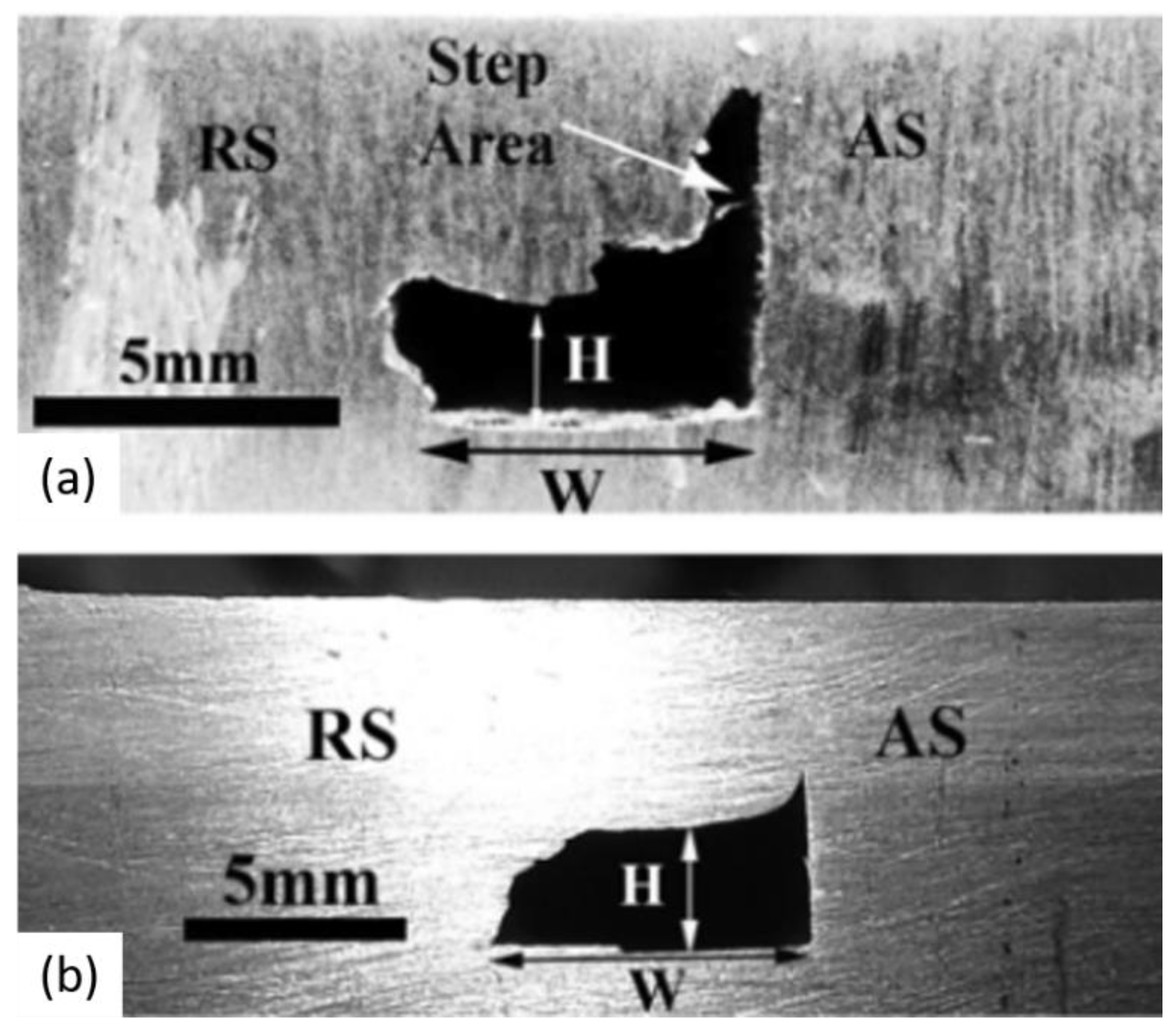
5.1.2. Channel Shape and Size

The material surrounding the tool pin undergoes preheating and softening due to the heat generated during the FSC. The resistance offered by the material decreases with higher heat input conditions, leading to a reduction in the process forces acting on the tool [78,79]. Conversely, lower heat input conditions result in higher process forces. Optimal channel formation is achieved with a moderate level of process forces, suggesting that higher heat input conditions are more conducive to producing well-structured channels compared to lower heat input conditions. Superior channel shapes can be attained by employing higher tool rotation speeds and lower tool traverse speeds. Channels are fabricated in various shapes, such as rectangular [33,54], elliptical [21], parallelogram [77], and tetragonal [20], based on the combination of different process parameters. Channel shape is further discussed in conjunction with other process parameters in the following sections.
A channel with a broad cross-section area is identified for the higher tool traverse speed and the lower tool rotation speed. Defect-free channels/are obtained in the optimum range of tool traverse and rotational speeds. The material flow is limited to the lower heat index condition. If the processing condition is too cold, the rotating material is inadequate to close the channel. The shoulder is unable to distribute the material uniformly over the channel region and remains non-closure of the flow at the AS. Consequently, the open channel is formed for extremely cold conditions. If the processing parameters are too high, discontinuous channels are formed [21].
The channel area can be identified from the equation below, where α, β, and K are the unknown coefficients found using the least square method.
Channel   cross section   area   =   K   × ( tool   rotational   speed ) α × tool   traverse   speed β  
The co-efficient α is negative, whereas β is positive for the FSC with threaded pin and clearance. The channel cross-section area with different sets of tool rotational and traverse speeds for two different plunge depths are shown in Figure 18a,b, respectively [21].
The size and integrity analysis are carried out for the channels formed by the unthreaded tool with the tilt angle [35]. Here, a tilt angle plays a vital role in the upward material flow and hence channel shape and size. The material gets softened at the higher tool rotation speed due to more heat generation. At elevated tool rotation speeds, the material undergoes softening due to increased heat generation. Consequently, the volume of material extracted is greater at higher tool rotation speeds, as the elevated heat input facilitates smoother material flow. Therefore, the cross-sectional area of the channel increases with an increase in tool rotation speed. A smaller channel is found in Figure 19a because of the lower tool rotation speed. The effect of tool rotation speed is compared in Figure 19a,c, where the tool traverse speed is constant. The maximum amount of material is extruded at the retreating side for the low tool rotation speed. Tool tilt angle increases the upward material flow with an increase in tool rotation speed. The amount of material pulled out by the tool pin from the leading edge to the trailing edge increases with tool rotation speed. Therefore, the extruded material at the retreating side decreases, which leads to a reduction in the X4 region, as shown in Figure 19a,c [35].
The effect of traverse speed on channel formation is analyzed in Figure 19b,c. The extruded material is not much affected by the traverse speed. Therefore, the width of the extruded material (X4) remains the same with the change in traverse speed, as shown in Figure 19b,c. However, the traverse speed influences the material flow above the channel. The increase in traverse speed reduces heat generation. The rotating material, along with the tool pin geometry, is insufficient for the defect-free nugget zone [80]. Consequently, the area of the step defect increases due to inadequate material flow just above the channel. In Figure 19c, the width of region X3 is significantly less due to the large step area. As a result, the channel area increases with an increase in tool traverse speed [35].

5.1.3. Surface Roughness of Channel Walls

The surface roughness of the fluid flow passage is critical for heat sink applications, especially when the size of the fluid passage is very small. Increased surface roughness enhances the surface contact area, thereby improving heat transfer. Additionally, higher surface roughness induces turbulent flow at low Reynolds numbers (<2000), further augmenting the heat transfer efficiency of FSC channels. However, increased roughness also results in a higher pressure drop for the fluid circulating within the channels. This pressure drop becomes a significant concern when the fluid path is extended and contains numerous turns and bends.
The surface roughness of channel walls is evaluated by the longitudinal cross-section, as shown in Figure 20. The wall surfaces show different topographic features based on their formation. Material is sheared at the AS, which is comparatively smoother than the RS. An excessively rough surface at RS is observed due to the extruded material deposited on the RS wall. The surface roughness of the RS wall is uniformly distributed along its length for a particular processing parameter. The channel roof is rough, and a feature generated on the surface shows linear tool movement direction. Three-dimensional images of the RS and channel bottom, AS, and channel roof (ceiling) at different tool rotational and traverse speeds are shown in Figure 21 [71]. The maximum surface roughness of RS is observed at lower tool rotational and traverse speeds. The surface becomes smooth with an increase in processing speeds. Inversely, the channel ceiling is smooth at low processing speeds, and the roughness increases with an increase in tool rotational and traverse speeds.

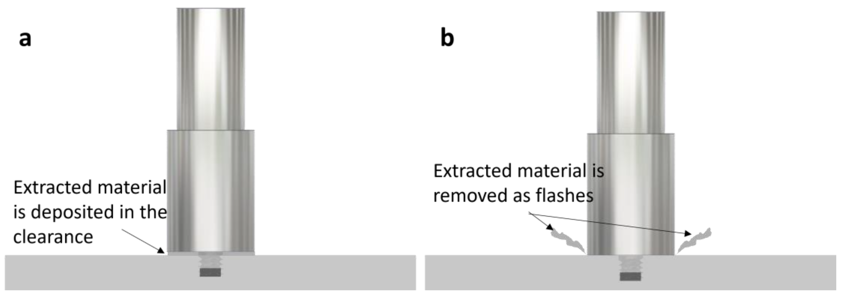
5.1.4. Tool Shoulder—Workpiece Clearance

The clearance between the tool shoulder and the workpiece significantly influences the channel size when employing a flat shoulder tool. This clearance regulates the upward material flow, enabling the deposition of this extruded material onto the workpiece surface. A larger tool shoulder-workpiece clearance facilitates greater material extraction, thereby increasing the channel size. Figure 22a–d illustrates the correlation between increased channel size and increasing clearance in aluminum alloy AA5083 under constant tool rotation speed and traverse speed. However, excessive clearance enhances the risk of defect formation in the channel roof. Voids and cracks observed during FSC at a clearance of 0.7 mm are depicted in Figure 22d. Therefore, an optimal clearance is recommended to maximize channel size while minimizing defects in the channel roof [81].
A comprehensive study examining the effects of tool rotation speed, traverse speed, and shoulder-workpiece clearance on process forces is depicted in Figure 23. Channels are fabricated in aluminum alloy AA6061-T6 under conditions of low heat input (tool rotation speed ω = 600 rpm, tool traverse speed ν = 150 mm/min) and high heat input (ω = 1600 rpm, ν = 40 mm/min). Additionally, the influence of tool shoulder-workpiece clearance on channel shape and size is presented for clearances of 0.8 mm and 1.2 mm. An increase in clearance value results in a reduction of the average forces experienced during the FSC process. Nevertheless, these forces are markedly lower in higher heat input conditions. The magnitude of these process forces has a significant impact on the channel shape and size. Under low heat input conditions, the channels exhibit irregular shapes, whereas higher heat input conditions result in comparatively smoother internal surfaces. The cross-sections of the channels for each condition are shown in the inset of Figure 23. At higher heat input with an increased clearance of 1.2 mm, a rectangular-shaped channel with an increased size is produced. Conversely, at lower heat input and higher clearance, insufficient material flow to the channel roof results in irregularly shaped, defective channels. Optimizing the process parameters is essential for fabricating defect-free channels with the desired shape, size, and internal surface roughness [19].

5.2. Tool Tilt Angle
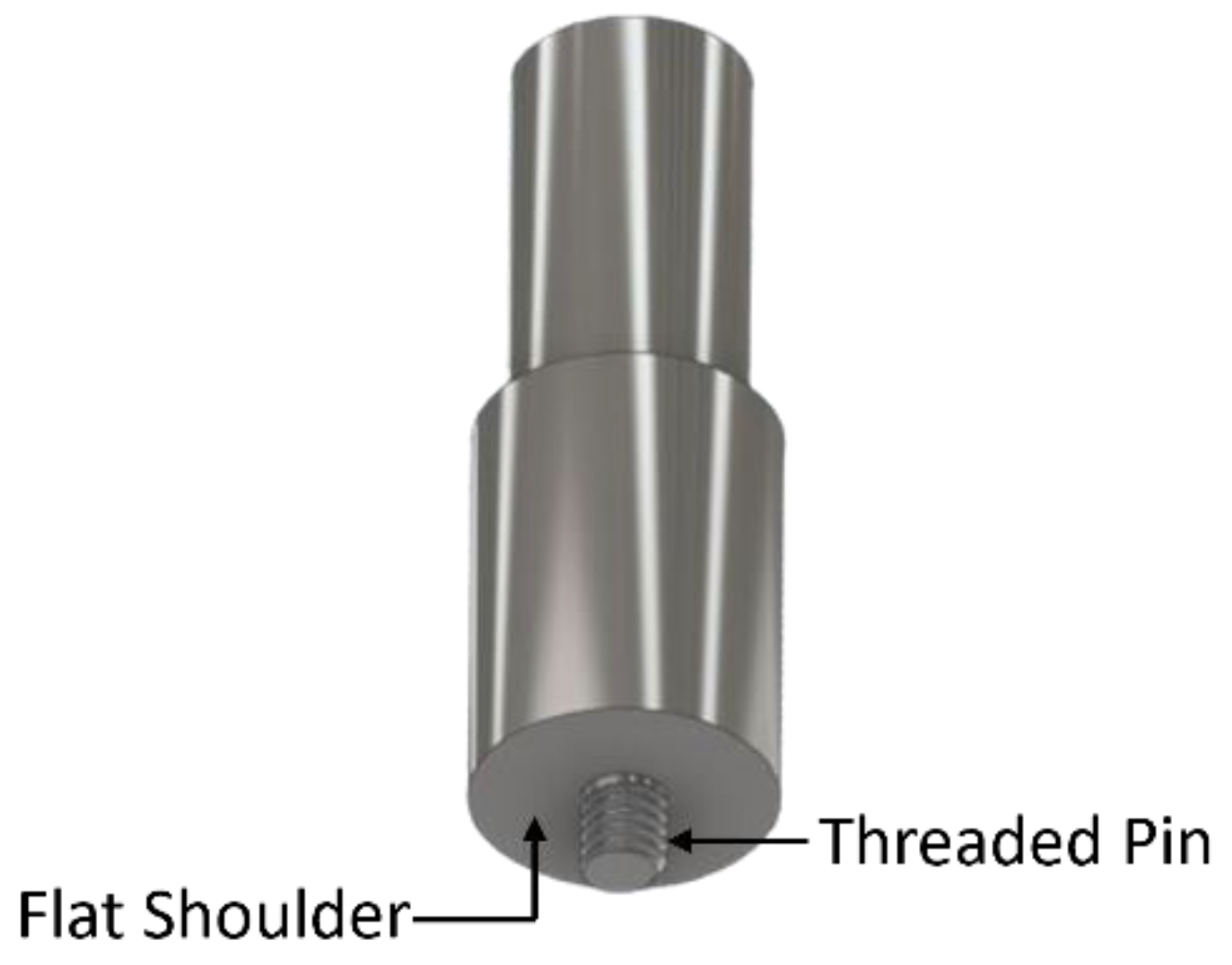
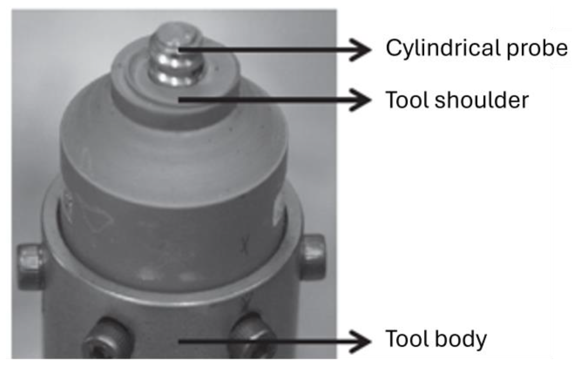
The tool tilt angle is the angle between the tool center line and normal line to the workpiece, where zero tilt angle represents the tool is normal to the workpiece. This angle represents the inclination of the tool shoulder relative to the upper surface of the workpiece. The tool tilt angle significantly influences the formation of step defects during the fabrication of channels using an unthreaded tool pin. At lower tilt angles (i.e., 2° and 2.5°), the material pulled out and rotating around the tool pin is insufficient, resulting in inadequate material flow and the formation of step defects on AS. These defects lead to irregularly shaped channels, as illustrated in Figure 23b and Figure 24a. Such step defects can cause abnormal failure under mechanical loads by reducing the distance between the channel and the workpiece’s upper surface.
Increasing the tilt angle to 3° enhances the material extraction and rotation around the pin, allowing for a greater material volume to fill the expected step defect region on the AS, thus forming rectangular-shaped channels. The channel integrity with different tilt angles is depicted in Figure 24a–c. This improvement in channel shape is attributed to the enhanced material flow in the nugget region. At a 3° tool tilt angle, tool-shoulder influence increases the forging force, thereby improving the downward material flow on the AS. The material flow characteristics in the nugget region are shown in Figure 24d, where the downward material flow responsible for eliminating step defects is indicated by blue and purple arrows. The tool tilt angle does not affect the material flow tendency from the leading to the trailing edge, as the width of region X4 in Figure 24 remains consistent regardless of the tool tilt angle [35].

5.3. Tool Geometry

The visco-plasticized material flows along with the threads of the tool pin. The material sheared from the workpiece rotates from the AS to the retreating side. A significant amount of material is extracted due to the upward flow along with the tool pin geometry. As a result, the continuous formation of voids due to the loss of the material fabricates a channel. Therefore, tool pin geometry plays a crucial role in the FSC process.

5.3.1. Depth of Cut, Thread Angle, and Pitch

Pin geometry parameters such as depth of cut and thread angle control the material flow tendency. As the depth of cut increases, more material is allowed to be extracted and form a larger void size. Therefore, channel size increases with an increase in the depth of cut and thread angle. The channel size, shape, and integrity for different depths of cut and thread angle are shown in Figure 25. The digits written in Figure 25 represent the cross-sectional area in mm2 [82].
The threads on the tool pin profile also influence the surface roughness of the advancing and retreating sides. The material shears and begins to rotate from the AS along the tool pin geometry. The tool pin profile also influences the surface of the extruded material on the retreating side. The surface roughness value decreases with an increase in thread pitch. Therefore, the smooth sidewalls of a channel are obtained for the higher thread pitch values [77]. Irrespective of the pitch, the highest surface roughness is observed for the channel roof, followed by RS, AS, and the channel bottom [77].

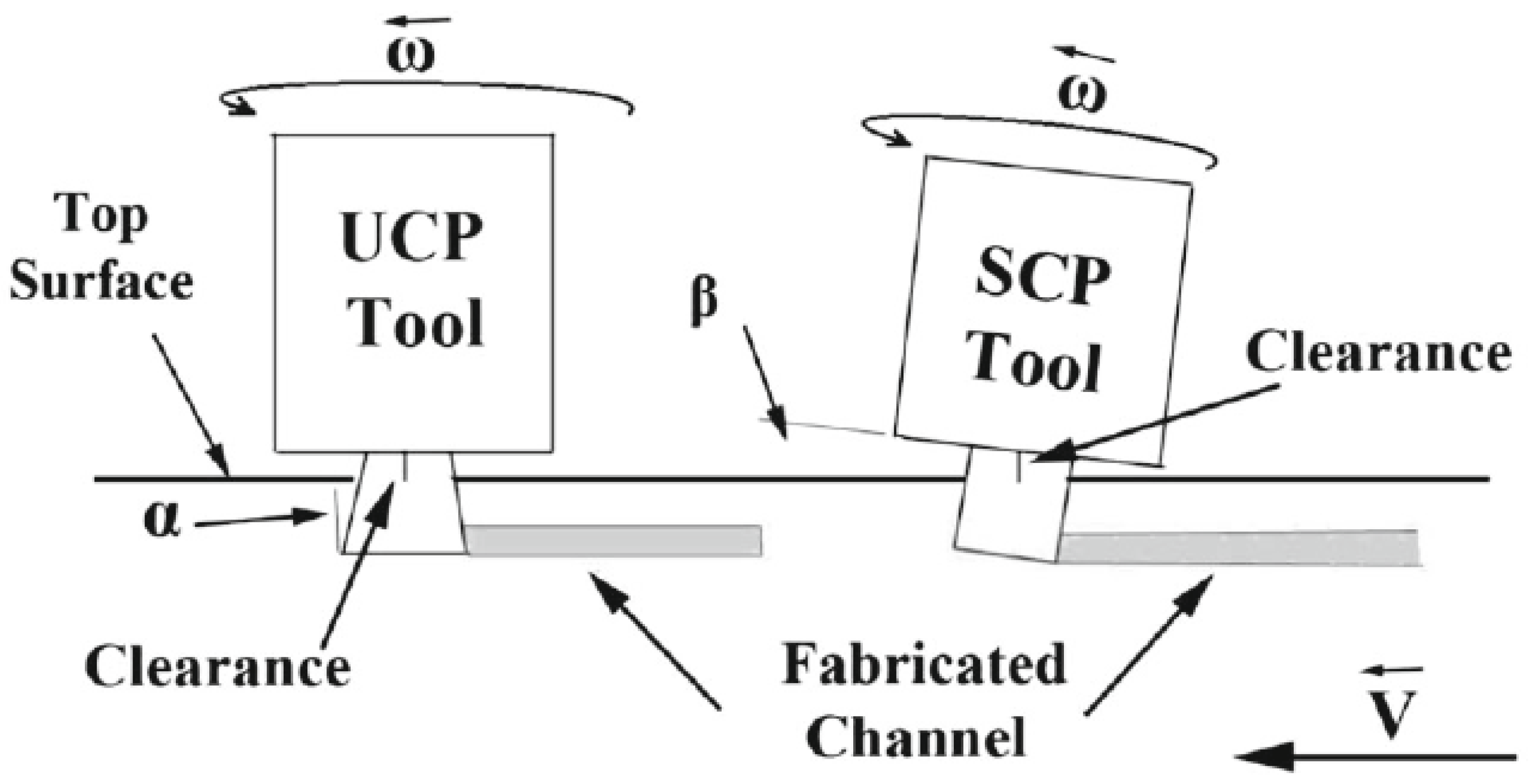
5.3.2. Upward Conical Pin Tool

The tilt angle is provided to extract the material upward to form the channel using the unthreaded tool. The tilt angle is incorporated in two aspects: (i) the physical tilting of the cylindrical tool-pin during the FSC process or (ii) providing the tilt angle on the tool-pin. In the second aspect, the pin with the upward conical profile is used to extract the material in place of physically tilting the tool. The size and integrity of the channels are different due to changes in the material flow. A significant amount of material rotates around the tool pin for the Upward Conical Pin (UCP) tool. Therefore, the pulled material increases at the AS just above the channel where the step defect may occur. Hence, the UCP tool eliminates the step defect, as shown in Figure 26. The channel height is also increased by 32% for the UCP tool compared to the physical tilting of the tool [73].
The selection of tool design and FSC process parameters is critical to obtaining defect-free, continuous, and integral channels with the desired shape and size. Defect-free channels are achieved through specific combinations of parameters, such as tool rotation speed and traverse speed, which ensure an optimal heat index to enhance material flow and fabricate a channel. The effect of heat generation on channel formation can be modified by external factors, such as external cooling or heating. Using a cooled copper backing plate facilitates faster heat extraction during the FSC process, enhancing channel stability. This approach enables the fabrication of channels across a wide range of heat index conditions, ensuring defect-free channels. Additionally, employing a cooled copper backing plate reduces the roughness of the internal channels, thereby lowering the pressure drop of the working fluid [83].

6. Mechanical Properties
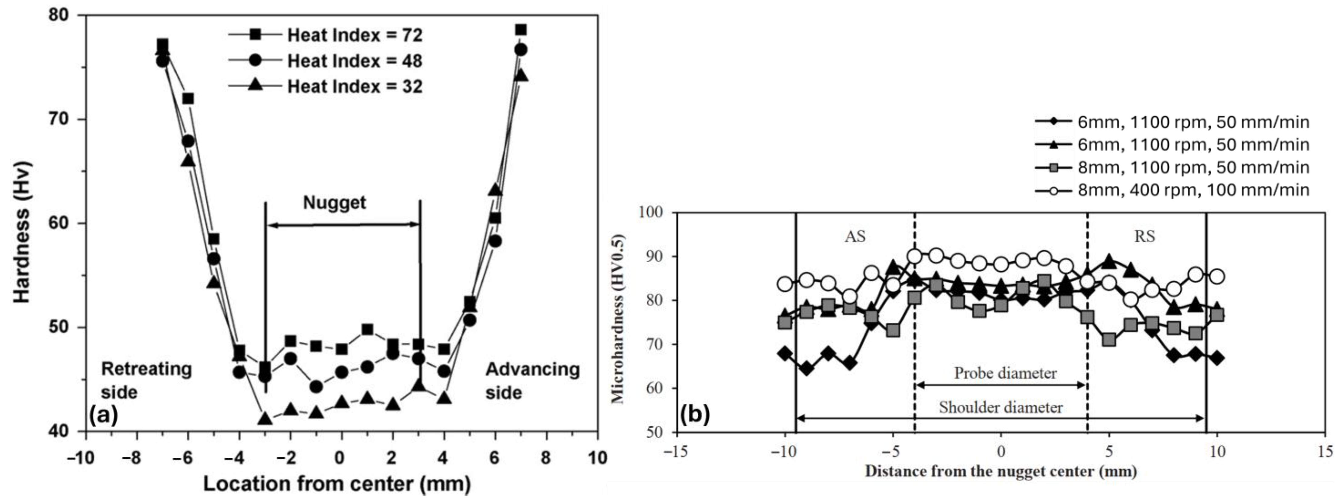
The heat exchangers formed using the FSC process may undergo mechanical loading. Furthermore, the stresses may be induced by thermal expansion and contraction. Mechanical properties such as hardness, tensile strength, and fatigue strength are attributed to the channel microstructure, material flow, and thermal variation. The mechanical properties also vary concerning the shape, size, and integrity of the channel. Here, the mechanical properties of the friction-stirred channels are analyzed and correlated with the microstructural characteristics in the vicinity of the channel.

6.1. Hardness

The microstructural variations in the channel vicinity are reflected in the hardness variations. Very fine equiaxed grains are formed in the nugget zone due to severe plastic deformation above the recrystallization temperature. Consequently, the nugget zone exhibits increased hardness compared to the AS and RS. Figure 27a depicts the microhardness distribution in the vicinity of the channel section in AA7178-T6. The hardness in the nugget is lower than that of the base material. Conversely, the non-heat-treatable aluminum alloy AA 5083-H111 is highly susceptible to strain hardening. Therefore, an increase in hardness is observed in the nugget zone and thermo-mechanically affected zone, exceeding the base material hardness, as depicted in Figure 27b. The strain-hardening aluminum alloys exhibit an increase in hardness within the nugget zone as a result of substantial plastic deformation occurring during friction stir-based processes [84,85,86]. The hardness at the AS and RS is close to the base material [30,71].
The hardness across the nugget zone between the channel and workpiece surface is measured for different processing parameters. A significant reduction in hardness is identified for the heat-treatable aluminum alloy AA 6061, as shown in Figure 28a. Material softening in the nugget zone is expected due to the coarsening or dissolution of precipitate particles. For the heat-treatable aluminum alloys, the strengthening precipitates start to dissolve in the solution matrix as the temperature crosses the solution limit [87,88,89]. Hence, the hardness reduces dramatically due to the annihilation of precipitation hardening [21].
The reduction in hardness is not observed in the strain-hardenable aluminum alloy AA 5083-H111 within the nugget region. Figure 28b presents the Vickers hardness measurements taken at the midpoint of the channel roof and the upper surface of the workpiece. The hardness within the nugget region is marginally higher compared to the AS and RS hardness values [55]. In another study of FSC in AA 5083-H111 alloy, a notable variation in hardness was observed in the vicinity of the channel. The nugget region, with a fragile layer of the RS channel wall, undergoes dynamic recrystallization. Therefore, peak hardness is observed in the nugget region. The hardness at the AS and RS follows an asymmetric trend as the material flow mechanism is different for both sides (Figure 29). Hardness is minimal in this region [77].

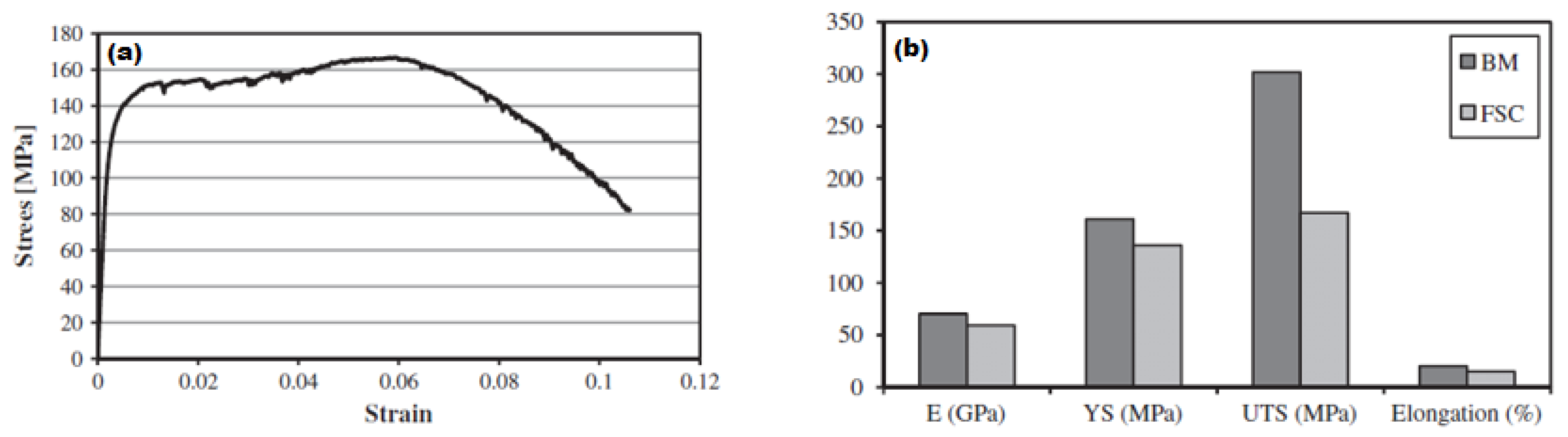
6.2. Tensile Strength

The tensile strength of the FSC specimen was assessed using a cylindrical specimen with a longitudinal channel. The stress-strain curve for the FSC is presented in Figure 30a. The tensile properties such as elastic modulus, yield strength (YS), ultimate tensile strength (UTS), and elongation are compared with the base material. The results are shown in Figure 30b. Interestingly, the channel specimen showed ductile behavior up to 10% of strain, although a significant microstructural variation was identified in the channel roof. As expected, the mechanical properties of the FSC channel are lower than those of the base material. A significant reduction in UTS leads to poor toughness [70].

6.3. Bending Strength

The influence of tool rotation speed and traverse speed on the bending strength is studied using four-point bending tests [30]. The channel area is found to be decreased with an increase in tool rotation speed at a constant tool traverse speed and a decrease with the increase in the tool traverse speed at a constant tool rotation speed. The reduction in channel area gives the closing layer more thickness. Closing layer thickness is a critical parameter, as the channel failure occurs by shearing this thickness under mechanical loading. Higher bending strength is obtained at high tool rotational speed and low tool traverse speed. The bending strength at different processing parameters is shown in Figure 31.

6.4. Fatigue Strength

Fatigue strength is one of the essential design criteria in engineering applications. The compact-size heat exchangers designed by the FSC process may undergo a fatigue load. Further, high-temperature performance is also necessary, as the applications are directly associated with thermal stresses. The fatigue analysis has been carried out under bending using a four-point bending test and under tension using uniaxial and biaxial tensile tests.

6.4.1. Four-Point Bend Fatigue Test

The fatigue analysis is carried out in load-controlled mode with sinusoidal four-point bending loading. The tests are also carried out at various temperatures to analyze fatigue behavior at higher temperatures [24,30]. A specimen is cut transverse to the channeling direction, and the load is applied normally to the channel. The applied load (P) is identified based on the below equation:
P = σ b h 2 3 w
where σ is maximum stress, and b ,   h , and w are the width, thickness, and smallest span of the specimen, respectively.
Fatigue strength is measured based on the S-N curve, where several cycles to fracture the specimens are obtained at different applied loads. The FSC specimens exhibit meager fatigue strength. The fatigue strength is reduced by 68.75% for the defect-free FSC specimen compared to the base material [55]. The fatigue strength is also firmly attributed to the working temperature. It decreases with an increase in temperature, and a significant difference is identified at 200 °C. A substantial drop in fatigue strength occurs due to the combined effect of thermally activated and time-dependent factors [24]. The fatigue life at different temperatures and peak stress conditions is shown in Figure 32. The reduction in the number of cycles also represents a loss of toughness at the higher temperature [24].
The closing layer thickness also plays a vital role in fatigue behavior. The distance between the channel and the top surface increases for the thicker closing layer specimen. Regardless of the channel cross-sectional area, the thicker closing layer specimens exhibit extended crack propagation periods. However, the crack propagation period is very short compared to the crack initiation period [24,31].
The fracture of the FSC specimen takes place at the nugget–TMAZ interface at the AS. The interface easily distinguishes between fine-equiaxed grains in the nugget zone and coarse grains in the TMAZ. The interface of nugget-TMAZ is identified in Figure 33a. The channel corner at the AS further amplifies the stress concentration effect at the nugget, TMAZ, and channel corner interaction points. Consequently, it acts as a crack initiation site, and it propagates under further loading.
A second crack initiates as the first crack reaches the top surface. It begins from the bottom channel corner and propagates towards the bottom workpiece surface. A schematic representation of both crack paths is shown in Figure 33b. The crack initiation corner (advancing or retreating side corner) depends on the shape of the channel bottom. The crack is initiated from the side where the distance between the channel bottom and the lower workpiece surface is minimal. Multiple ratchet marks found on the channel surface may act as crack initiation sites, as shown in Figure 34. The ratchet marks at the channel bottom indicate that the crack is initiated at the channel bottom and on the outer surface [24,31].
The fatigue fracture morphology is affected by the testing temperature. A fracture due to a combined mode of intergranular and transgranular cracking occurs at room temperature. Such cracking is shown in Figure 35a. Intergranular cracking is more common at higher temperatures [24,31]. The progressive stages of crack propagation are observed during high-temperature fatigue testing, which indicates multiple crack origins. The fracture surface becomes smooth with an increase in testing temperature [24]. A smooth fracture surface found at 200 °C is shown in Figure 35b.

6.4.2. Uniaxial and Biaxial Tests

Uniaxial and biaxial fatigue tests were performed using sinusoidal loading at a constant frequency rate. The FSC specimen undergoes axial and torsional shear stresses during a biaxial test. Uniaxial fatigue strength is very low compared to the base material. The fatigue life of friction stir channels and base material at different stresses is shown in Figure 36. The fatigue limit of the FSC specimen has been measured at 9% of the yield stress. FSC specimens cannot be used under biaxial loading conditions due to the thinner closing layer [70]. The first crack initiation and propagation in uniaxial/biaxial loading are similar to the four-point bending test. The second crack initiates in the transverse direction to the specimen axis. This crack propagates radially along with the path nugget-TMAZ interface—stirred zone—base material for both uniaxial and biaxial fatigue stress conditions.

7. Channel Performance

It is challenging to fabricate a channel in non-linear profiles at a low cost and with excellent microstructural properties using conventional manufacturing techniques. Water-based heat sinks can efficiently cool the component as the heat transfer coefficient of water for forced convection is considerably higher than that of air [20]. A vast field of thermal systems is associated with the heat transfer rate, and therefore FSC can be directly incorporated into such applications [90]. The channels can also be fabricated in a helical serpentine profile on a tubular workpiece, as shown in Figure 37. Compact heat exchangers are critically required to cool high-performance data centers [91,92,93], electronic components [94], aerospace applications [95], nuclear reactors [96], and communication systems [97]. The channels are useful to make a lubrication network for hydraulics. The cooling channels incorporated in thin-wall motor casings provide active cooling, reduce complexity and overall weight, and improve motor performance [36,98].
Hybrid FSC technology can be employed to design thermal management systems for cooling EV battery cells, as depicted in Figure 38. This approach achieves two key objectives of heat sinks: firstly, it forms channels in a serpentine profile, recognized as optimal for battery cell cooling efficiency [9], and secondly, it seamlessly welds these channels to the base to enhance heat transfer. The distinct material flow required for channel formation and welding is facilitated by the probe design of the FSC tool. In this process, channels are crafted in 8-mm thick aluminum alloy 5083 while simultaneously welding them with 3-mm thick oxygen-free copper. These heat sinks are integrated into battery packs to optimize the thermal management systems for battery cell cooling [37].
The axial wall conduction through channel walls is calculated using the thermo-hydraulic performance. The de-ionized water is used as a working fluid and flows at different Reynolds numbers. A digitally controlled DC power source controls the heat supply to the specimen. The temperature variation along the axial direction is measured using T-type thermocouples placed at the channel sidewalls. A peristaltic pump regulates the mass flow, whereas a damper is used to ensure smooth flow. The experimental setup to measure axial wall conduction is shown in Figure 39. The effect of axial wall conduction is analyzed using the numerical model as well [99].
Channel geometry identified using X-ray tomography is used for numerical modeling. The flow is considered turbulent even at the low Reynolds number due to the rough and irregular surface of the channel walls. Water viscosity changes with temperature. The governing equations for continuity, momentum, and energy equilibrium equations are solved for steady, incompressible, and Newtonian fluid flow [99].
Fluid flow is provided at the channel inlet such that the Reynolds number of the model remains the same as in the experiments. Heat is supplied from the channel bottom, which has a constant heat input at the plate center. The remaining plate is considered adiabatic, and the heat transfer proceeds to place at the solid-fluid interface. The boundary conditions for the heat transfer prediction are shown in Figure 40. The influence of the surface roughness of the channel walls on the heat transfer performance was estimated by the average Nusselt number [99].
Axial wall conduction at the fluid-plate interface significantly affects the heat transfer rate. The wall temperature is not distributed uniformly throughout the channel length. The wall temperature increases at the entrance up to the middle of the channel length and then decreases at the channel end. The reduction in the wall temperature is attributed to axial wall conduction. The bulk fluid temperature increases throughout the length due to the heat absorption by the fluid. Numerically predicted wall temperatures are higher than experimental values for all Reynolds numbers. Similarly, the numerical bulk fluid temperature is higher compared to the experimental fluid flow temperature. Numerical bulk fluid temperature is linear for the low Reynolds numbers, and it slightly decreases at the end region. The variation in experimental and numerical results of channel wall temperatures and bulk fluid temperatures at different fluid flow rates is shown in Figure 41a–d [99].
The numerically predicted local heat flux at different locations of the channel wall–fluid interface is shown in Figure 41e. The local heat is not uniform throughout the channel length. It slightly increases at the inlet and decreases rapidly near the end region. The combination of convective heat transfer by the fluid and conductive heat transfer by the channel walls leads to unconventional variations in the heat flux. The variation in the heat flux throughout the length is significant for the lower Reynolds number, and the difference in the heat flux distribution decreases with an increase in the Reynolds number. The reduction in the heat flux variation is attributed to the decrease in axial wall conduction at a higher Reynolds number. Péclet number (Pe) is also determined as it affects the axial wall conduction. Higher thermal conductivity of the substrate and a higher ratio of wall area to channel cross-section area nullify the effect of a higher Péclet number.
The heat transfer performance of cooling channels fabricated in 6-mm thick aluminum and copper plates is compared using compressed air as the working fluid and immersing the plates in 50 °C water. Compressed air at 34 °C is circulated in the channels at various flow rates. The copper channels demonstrate superior cooling performance, considering the higher thermal conductivity of copper compared to aluminum. This enhanced performance of the copper channels is consistent across all tested flow rates. Figure 42a illustrates the variation in water temperature over time, while Figure 42b depicts the cooling powers of copper and aluminum channels at different compressed air flow rates [100].
The heat transfer capacity of the hybrid friction stirred channel is compared with that of the milled channel. The retreating side and the top surface of the friction-stirred channel exhibit significantly higher roughness than those of the milled channel. Friction-stirred and milled channels with a similar size, length, and hydraulic diameter are considered so that heat transfer only attributed to the surface properties of the channel walls can be analyzed. The fluid flow is turbulent during the friction stir channels due to multiple micro paths in the channel. The vortices in the coolant flow are also created due to rough channel walls, which further helped to improve the cooling rate [20].
Two heat sink prototypes are manufactured using HFSC and milling processes for cooling an electronic device, as shown in Figure 43a,b. The milled section is sealed with a screwed lid to form an internal channel roof. A circuit includes a printed wiring board (PWB), thermal interface materials, and six resistors, which act as heat sources. Water–ethylene glycol solution is used as a coolant. The fluid flow is circulated at constant velocity in both friction-stirred and milled channels. The temperature of the coolant inlet, coolant outlet, heat sink, and ambient is measured using K-type thermocouples. The schematic of an experimental setup to measure the thermal performance of the channels is shown in Figure 43c [20].
The inlet temperature is also measured for all Reynolds numbers. The lower temperature difference in the HFSC channel reflects better cooling performance compared to the milled channel. The cooling performance of the HFSC is more efficient at all flow rates, as shown in Figure 44a. Inlet temperature also influences heat sink temperature. A considerable difference is not observed at the 2500 Reynolds number for the milled channel because of the increased inlet temperature. The temperature difference between the heat sink and the ambient is 30 to 40% lower in HFSC compared to the milled channel for steady-state conditions. This difference increases with an increase in flow rate. Better cooling performance is attributed to the surface roughness of the channel walls. The cooling rate is an important aspect of the cooling of electronic systems. Heat sinks with a higher cooling rate can effectively cool down the system against sudden increases in heat fluxes and improve product service life. The maximum cooling rate for the HFSC channel is 33% higher than the milled one for the transient state, as shown in Figure 44b [20].
The surface roughness of the channel walls formed is higher in the HFSC compared to milled channels. High surface roughness improves the cooling rate as turbulent flow can occur at the lower Reynolds number of the coolant flow. On the other hand, higher surface roughness increases the flow resistance, which leads to the drop in coolant pressure. Therefore, more mechanical power is required to flow the coolant at all flow rate values in hybrid friction stir channels. The required power difference also increases with an increase in the flow rate, as shown in Figure 44c. The cooling efficiency can be estimated based on the temperature drop of the heat sink for the equivalent coolant pump power. The cooling efficiency of HFSC prevails over the milled channels at all levels of inlet power (Figure 44d). Here, the power consumption significantly increases with an increase in flow rate, but it does not improve the cooling performance [20].

8. Future Scope

Channels have been successfully carried out in heat-treatable and non-heat-treatable aluminum alloys. The heat transfer rate of copper is even better than that of aluminum due to its higher thermal conductivity. However, channel fabrication using the FSC process is limited to aluminum alloys only, and the feasibility of other materials is not much explored. FSC in copper can enhance heat sink applications in the aerospace and nuclear industries. The channel feasibility can also be tested for the steels. The effect of the tool shoulder is critical to heat generation and channel formation. The channel’s feasibility can also be tested for the stationary tool shoulder.
Researchers have fabricated channels using different tool geometries. These geometries help to extract the material in different ways. Therefore, channel profiles with different shapes, sizes, and integrity have been registered during the FSC of aluminum alloys. The material flow during different FSC concepts is different, and it affects the microstructural and mechanical properties of the channel. Comparative analysis of the tool geometry can provide a better understanding of the tool selection and channeling process.
The 3-dimensional complex material flow has been analyzed experimentally using different techniques. The channel shape and size make it possible to predict if the material flow can be fully analyzed using numerical modeling. The heat transfer rate and pressure drop have been identified for the linear and serpentine channel profiles, and the same is predicted numerically. The complex shapes can be incorporated to determine the pressure drop due to the sharp bend and turn. The effect of heat on the channel geometry can be studied by providing external parameters such as a heating plate to enhance the heat supply or a water submerged FSC for faster heat dissipation. The channel properties may vary due to a combination of different heat and material flow characteristics. The friction stir channels can be filled with reinforcement particles, and FSP can be carried out to enhance the surface properties up to a certain depth.

Conclusions

This review paper emphasizes channel formation through friction stir channeling. Various tool designs have been used to enhance material flow in the channel vicinity. The complex three-dimensional material flow during the FSC process results in integral changes in the desired path. Distinct features of FSC, such as processing from the surface end, a single-step process for fabricating integral channels, and the higher roughness of the internal channel surfaces, make the process futuristic for fabricating the heat sinks. The research conducted on the FSC technology is summarized as follows:
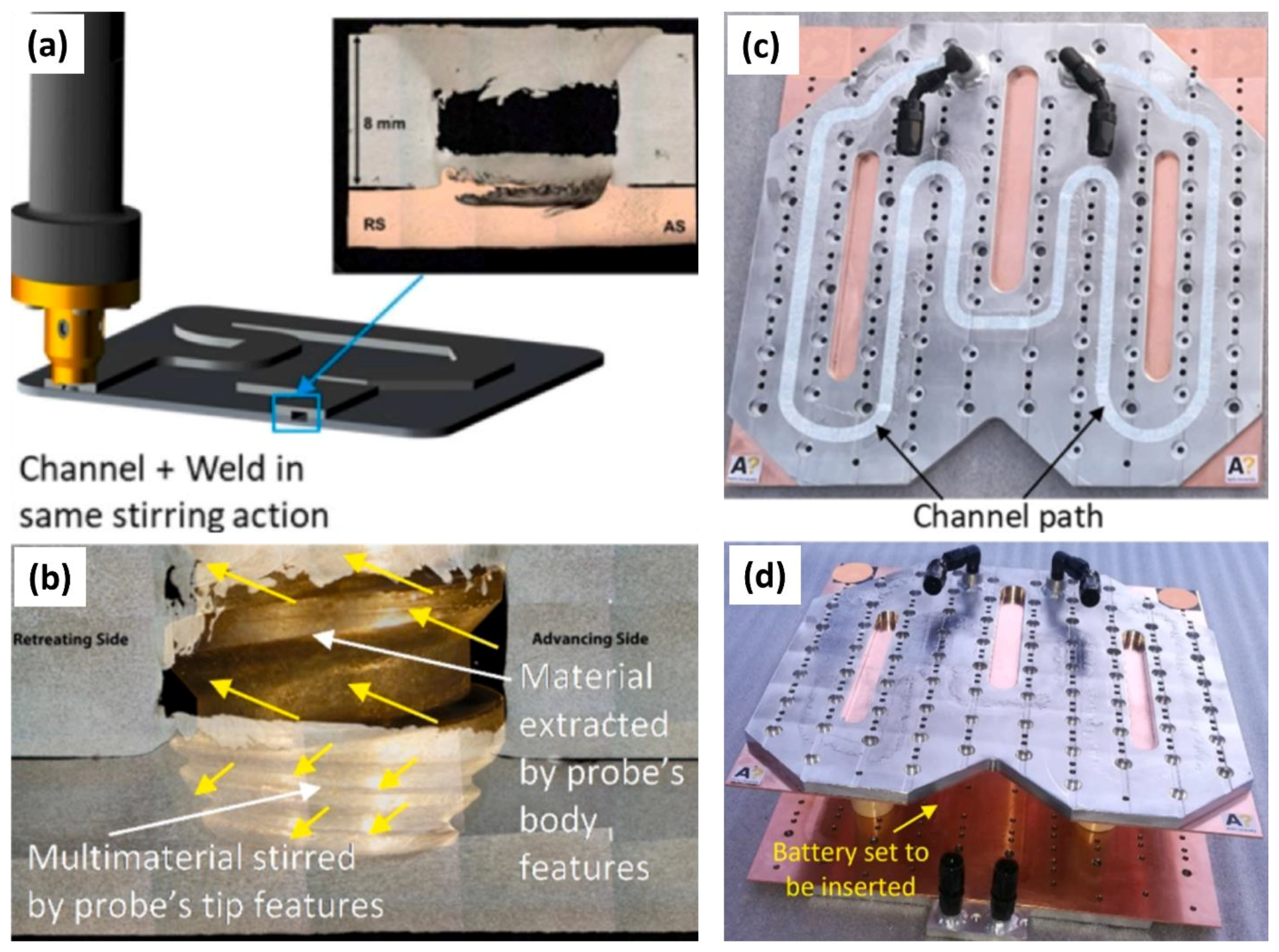
  • Channels are formed due to upward-rotational material flow, with the tool pin geometry being a critical factor in directing the material flow toward the channel formation.
  • Material flow is not consistent along the path geometry. In serpentine profiles, larger channels are created when the advancing side (AS) is on the inner curve, attributed to increased upward material flow and fewer shear layers.
  • Processing Parameters such as tool rotation speed, traverse speed, and tilt angle govern the channel shape, size, and integrity. Higher tool rotation speeds combined with lower traverse speeds enhance heat generation, promoting material flow due to increased material softening. Optimal channels are produced within a specific range of tool traverse and rotational speeds.
  • Severe plastic deformation at elevated temperatures in the nugget zone leads to dynamic recrystallization, increasing the hardness of strain-hardenable alloys. At high temperatures, precipitate dissolution causes a significant drop in nugget zone hardness.
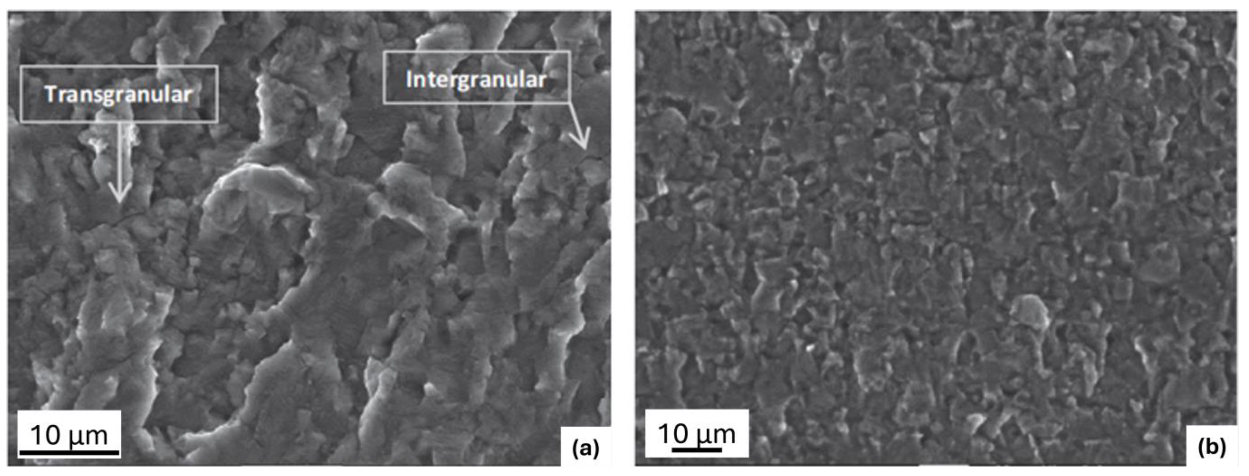
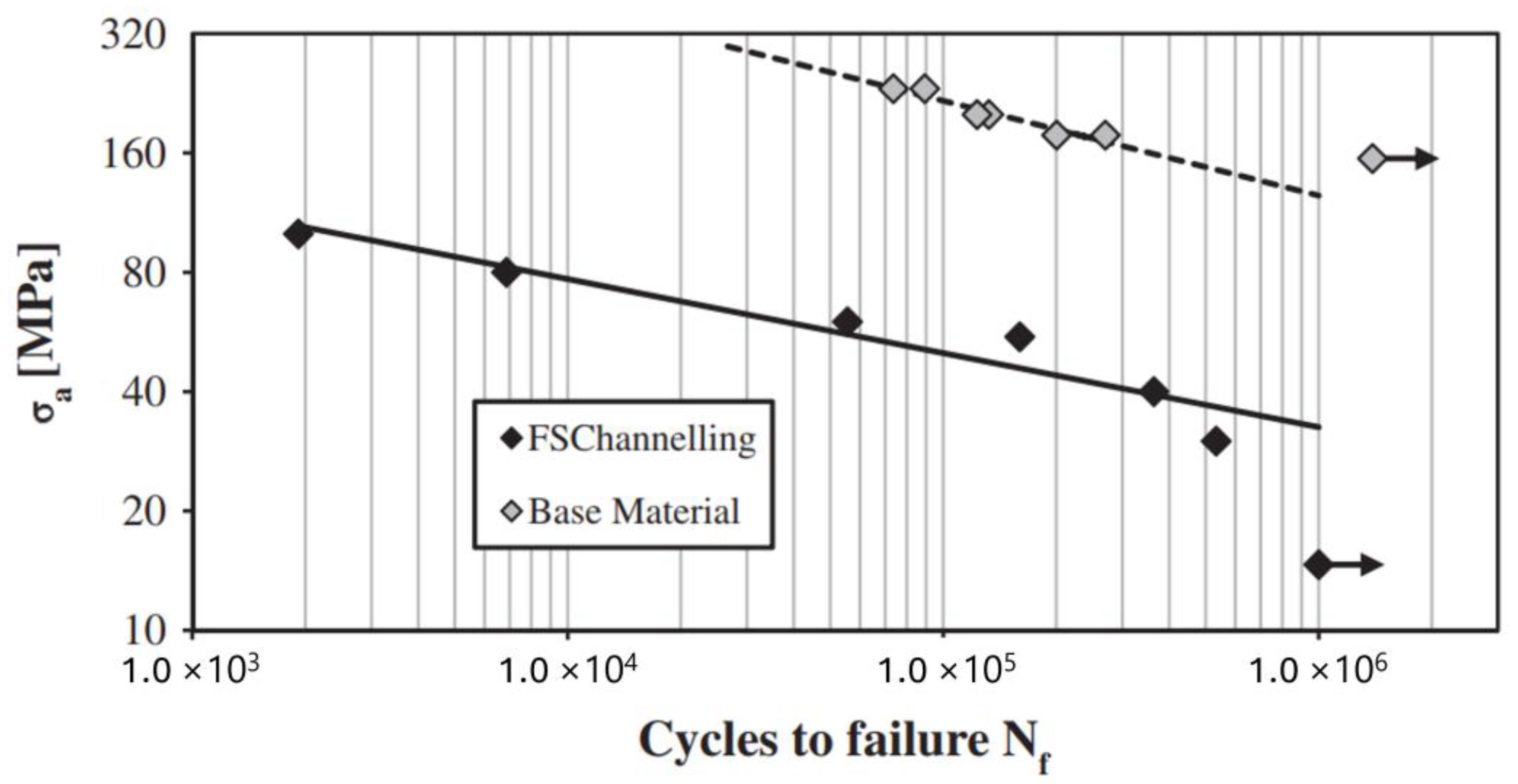
  • FSC specimens exhibit lower fatigue strength than the parent metal, with fatigue strength further decreasing at higher temperatures. Regardless of channel size, specimens with a thicker closing layer show a longer crack propagation period.
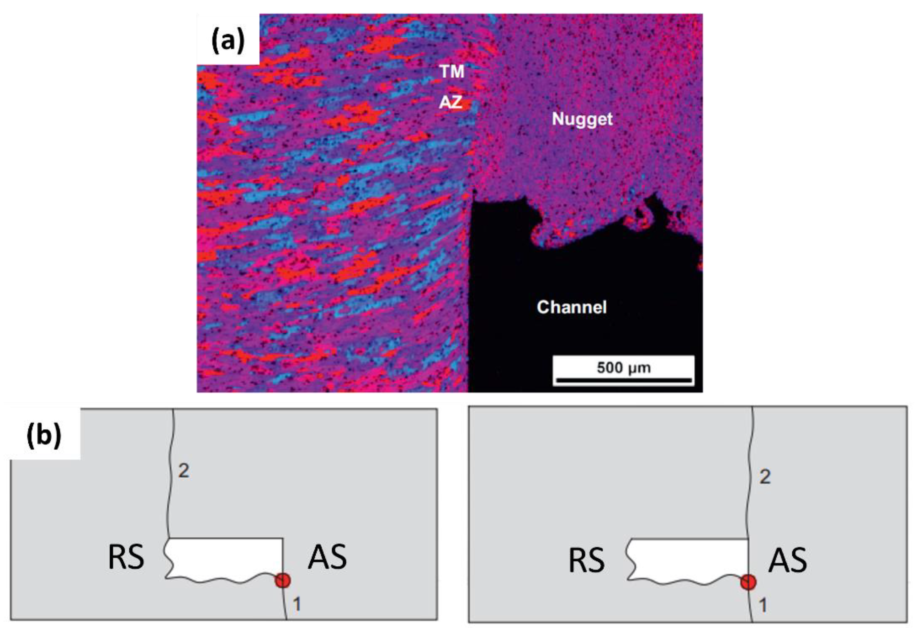
  • A distinct interface separates fine equiaxed grains in the nugget zone from coarse grains in the TMAZ. The corner at the nugget zone-TMAZ interface on the AS amplifies stress concentration, initiating the cracks that propagate upward through the interface.
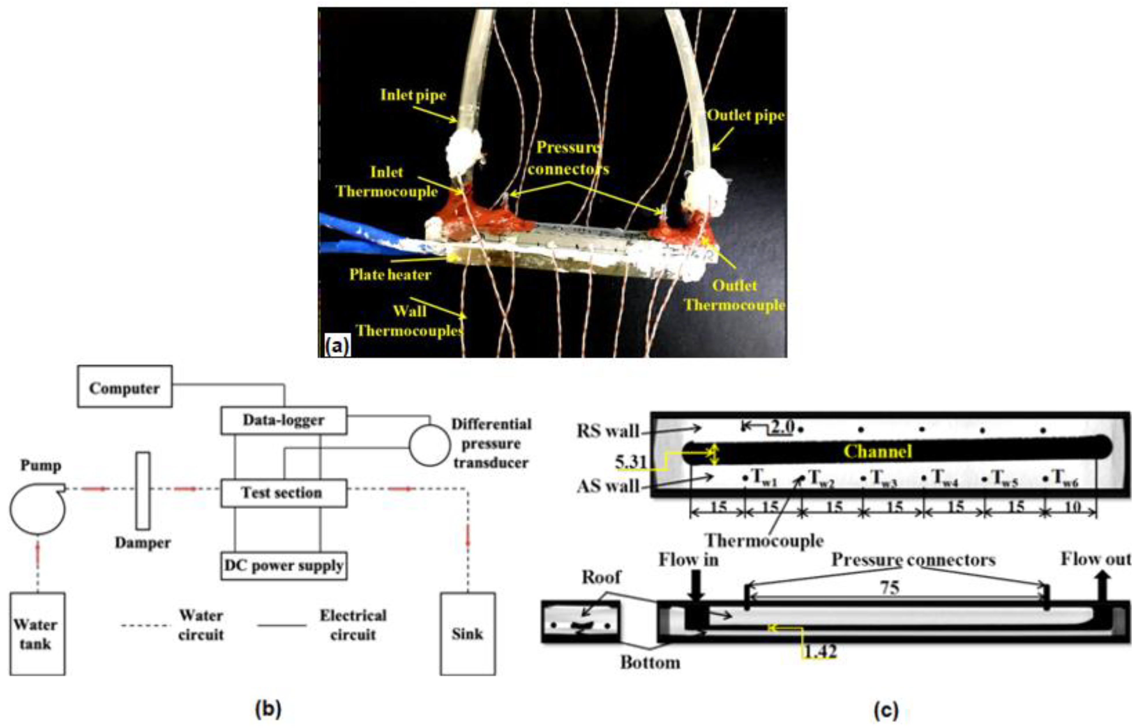
  • Higher surface roughness increases surface area and creates turbulent flow at low Reynolds numbers, enhancing heat transfer in friction stir channels.
This review article delineates the intricate mechanisms and influences affecting FSC, providing a comprehensive understanding of the factors driving channel formation and their implications on material properties.

Author Contributions

Conceptualization, S.P. and A.A.; writing—original draft preparation, S.P.; writing—review and editing, A.A.; visualization, S.P.; supervision, A.A.; project administration, A.A.; funding acquisition, A.A. All authors have read and agreed to the published version of the manuscript.

Funding

This research was funded by the Board for Research in Nuclear Sciences (BRNS), (project number 57/14/05/2019-BRNS/).

Acknowledgments

The authors express their gratitude for the support received from members of the Advanced Materials Processing Research Group, Indian Institute of Technology Gandhinagar, Gandhinagar 382355, Gujarat, India, and the University of Oklahoma, Norman, OK 73019, USA.

Conflicts of Interest

The authors declare no conflict of interest.

References

  1. Ambrose, H.; Kendall, A.; Lozano, M.; Wachche, S.; Fulton, L. Trends in life cycle greenhouse gas emissions of future light duty electric vehicles. Transp. Res. Part D Transp. Environ. 2020, 81, 102287. [Google Scholar] [CrossRef]
  2. Electric Vehicle Database. Available online: https://ev-database.org/car/1405/Tesla-Model-S-Plaid (accessed on 14 July 2024).
  3. Rao, Z.; Wang, S. A review of power battery thermal energy management. Renew. Sustain. Energy Rev. 2011, 15, 4554–4571. [Google Scholar] [CrossRef]
  4. Lu, M.; Zhang, X.; Ji, J.; Xu, X.; Zhang, Y. Research progress on power battery cooling technology for electric vehicles. J. Energy Storage 2020, 27, 101155. [Google Scholar] [CrossRef]
  5. Lyu, Y.; Siddique, A.; Majid, S.; Biglarbegian, M.; Gadsden, S.; Mahmud, S. Electric vehicle battery thermal management system with thermoelectric cooling. Energy Rep. 2019, 5, 822–827. [Google Scholar] [CrossRef]
  6. Bandhauer, T.M.; Garimella, S.; Fuller, T.F. A Critical Review of Thermal Issues in Lithium-Ion Batteries. J. Electrochem. Soc. 2011, 158, R1. [Google Scholar] [CrossRef]
  7. Pesaran, A. Battery thermal models for hybrid vehicle simulations. J. Power Sources 2002, 110, 377–382. [Google Scholar] [CrossRef]
  8. Hamed, M.M.; El-Tayeb, A.; Moukhtar, I.; El Dein, A.; Abdelhameed, E.H. A review on recent key technologies of lithium-ion battery thermal management: External cooling systems. Results Eng. 2022, 16, 100703. [Google Scholar] [CrossRef]
  9. Benabdelaziz, K.; Lebrouhi, B.; Maftah, A.; Maaroufi, M. Novel external cooling solution for electric vehicle battery pack. Energy Rep. 2020, 6, 262–272. [Google Scholar] [CrossRef]
  10. Panchal, S.; Khasow, R.; Dincer, I.; Agelin-Chaab, M.; Fraser, R.; Fowler, M. Thermal design and simulation of mini-channel cold plate for water cooled large sized prismatic lithium-ion battery. Appl. Therm. Eng. 2017, 122, 80–90. [Google Scholar] [CrossRef]
  11. Ye, B.; Rubel, R.H.; Li, H. Design and optimization of cooling plate for battery module of an electric vehicle. Appl. Sci. 2019, 9, 754. [Google Scholar] [CrossRef]
  12. Huang, Y.; Mei, P.; Lu, Y.; Huang, R.; Yu, X.; Chen, Z.; Roskilly, A.P. A novel approach for Lithium-ion battery thermal management with streamline shape mini channel cooling plates. Appl. Therm. Eng. 2019, 157, 113623. [Google Scholar] [CrossRef]
  13. Balasubramanian, N. Friction Stir Channeling: An Innovative Technique for Heat Exchanger Manufacturing; Missouri University of Science and Technology: Rolla, MO, USA, 2008. [Google Scholar]
  14. Mei, F.; Parida, P.R.; Jiang, J.; Meng, W.J.; Ekkad, S.V. Fabrication, assembly, and testing of Cu- and Al-based microchannel heat exchangers. J. Microelectromech. Syst. 2008, 17, 869–881. [Google Scholar] [CrossRef]
  15. Collins, I.L.; Weibel, J.A.; Pan, L.; Garimella, S.V. A permeable-membrane microchannel heat sink made by additive manufacturing. Int. J. Heat Mass Transf. 2019, 131, 1174–1183. [Google Scholar] [CrossRef]
  16. Narendran, G.; Mallikarjuna, B.; Nagesha, B.K.; Gnanasekaran, N. Experimental investigation on additive manufactured single and curved double layered microchannel heat sink with nanofluids. Heat Mass Transf. Und Stoffuebertragung 2023, 59, 1311–1332. [Google Scholar] [CrossRef]
  17. Kempers, R.; Colenbrander, J.; Tan, W.; Chen, R.; Robinson, A. Experimental characterization of a hybrid impinging microjet-microchannel heat sink fabricated using high-volume metal additive manufacturing. Int. J. Thermofluids 2020, 5–6, 100029. [Google Scholar] [CrossRef]
  18. Mehta, K.P.; Vilaça, P. A review on friction stir-based channeling. Crit. Rev. Solid State Mater. Sci. 2021, 47, 1–45. [Google Scholar] [CrossRef]
  19. Sarkar, P.; Pal, S.K.; Bhattacharya, A.; Shollock, B. The influence of shoulder-workpiece clearance on channel formation during friction stir channeling at low and high heat inputs. J. Manuf. Process 2023, 101, 701–713. [Google Scholar] [CrossRef]
  20. Karvinen, H.; Nordal, D.; Galkin, T.; Vilaça, P. Application of hybrid friction stir channeling technique to improve the cooling efficiency of electronic components. Weld. World 2018, 62, 497–509. [Google Scholar] [CrossRef]
  21. Balasubramanian, N.; Mishra, R.; Krishnamurthy, K. Friction stir channeling: Characterization of the channels. J. Mater. Process Technol. 2009, 209, 3696–3704. [Google Scholar] [CrossRef]
  22. Mishra, R.S.; Ma, Z.Y. Friction stir welding and processing. Mater. Sci. Eng. R Rep. 2005, 50, 1–78. [Google Scholar] [CrossRef]
  23. Godet, M. The third-body approach: A mechanical view of wear. Wear 1984, 100, 437–452. [Google Scholar] [CrossRef]
  24. Vidal, C.; Infante, V.; Vilaça, P. Characterisation of fatigue fracture surfaces of friction stir channelling specimens tested at different temperatures. Eng. Fail. Anal. 2015, 56, 204–215. [Google Scholar] [CrossRef]
  25. Heidarzadeh, A.; Mironov, S.; Kaibyshev, R.; Çam, G.; Simar, A.; Gerlich, A.; Khodabakhshi, F.; Mostafaei, A.; Field, D.; Robson, J.; et al. Friction stir welding/processing of metals and alloys: A comprehensive review on microstructural evolution. Prog. Mater. Sci. 2021, 117, 100752. [Google Scholar] [CrossRef]
  26. El-Sayed, M.M.; Shash, A.; Abd-Rabou, M.; ElSherbiny, M.G. Welding and processing of metallic materials by using friction stir technique: A review. J. Adv. Join. Process. 2021, 3, 100059. [Google Scholar] [CrossRef]
  27. Singh, V.P.; Patel, S.K.; Ranjan, A.; Kuriachen, B. Recent research progress in solid state friction-stir welding of aluminium–magnesium alloys: A critical review. J. Mater. Res. Technol. 2020, 9, 6217–6256. [Google Scholar] [CrossRef]
  28. Balasubramanian, N.; Mishra, R.S.; Krishnamurthy, K. Development of a mechanistic model for friction stir channeling. J. Manuf. Sci. Eng. Trans. ASME 2010, 132, 054504. [Google Scholar] [CrossRef]
  29. Vidal, C. Development and Mechanical Characterization of a New Manufacturing Technology: Friction Stir Channelling. Ph.D. Dissertation, Universidade De Lisboa, Lisbon, Portugal, 2014. [Google Scholar]
  30. Vidal, C.; Infante, V.; Vilaça, P. Fatigue behaviour at elevated temperature of friction stir channelling solid plates of AA5083-H111 aluminium alloy. Int. J. Fatigue 2014, 62, 85–92. [Google Scholar] [CrossRef]
  31. Vidal, C.; Baptista, R.; Infante, V. Experimental and numerical investigation on the fatigue behaviour of friction stirred channel plates. Eng. Fail. Anal. 2019, 103, 57–69. [Google Scholar] [CrossRef]
  32. Filgueiras, M.; Ferraz, S.; Pedro, D.; Vilaça, S. Friction Stir Channeling Industrial Applications Prototype Design and Production May 2012 Agradecimentos. Master’s Thesis, Technical Universty of Lisboa, Lisbon, Portugal, 2012. [Google Scholar]
  33. Rashidi, A.; Mostafapour, A.; Salahi, S.; Rezazadeh, V. modified friction stir channeling: A novel technique for fabrication of friction stir channel. Appl. Mech. Mater. 2013, 302, 365–370. [Google Scholar] [CrossRef]
  34. Rashidi, A.; Mostafapour, A. Influence of tool pin geometry and moving paths of tool on channel formation mechanism in modified friction stir channeling technique. Int. J. Adv. Manuf. Technol. 2015, 80, 1087–1096. [Google Scholar] [CrossRef]
  35. Rashidi, A.; Mostafapour, A. Influence of machine parameters on material flow behavior during channeling in modified friction stir channeling. Int. J. Mater. Form. 2014, 9, 1–8. [Google Scholar] [CrossRef]
  36. Gandra, J. Coreflow: A Sub-Surface Machining Process. Available online: https://www.twi-global.com/media-and-events/insights/coreflow-a-sub-surface-machining-process (accessed on 22 September 2020).
  37. Karvinen, H.; Mehta, K.P.; Vilaça, P. Novel manufacturing of multi-material component by hybrid friction stir channeling. CIRP J. Manuf. Sci. Technol. 2023, 45, 271–284. [Google Scholar] [CrossRef]
  38. Nordal, D. Design, Development and Analysis of Tools for Hybrid Friction Stir Channeling. Master’s Thesis, Aalto University, Espoo, Finland, 2017. [Google Scholar]
  39. Yan, F.; Zhang, Y.; Fu, X.; Li, Q.; Gao, J. A new calculating method of frictional heat and its application during friction stir welding. Appl. Therm. Eng. 2019, 153, 250–263. [Google Scholar] [CrossRef]
  40. Chiumenti, M.; Cervera, M.; de Saracibar, C.A.; Dialami, N. Numerical modeling of friction stir welding processes. Comput. Methods Appl. Mech. Eng. 2013, 254, 353–369. [Google Scholar] [CrossRef]
  41. Mahesh, V.P.; Patel, S.; Gumaste, A.; Arora, A. Joining of Polymer Matrix Composites Through Friction Stir Processes. Encycl. Mater. Compos. 2021, 3, 352–379. [Google Scholar]
  42. Sun, Z.; Wu, C.; Kumar, S. Determination of heat generation by correlating the interfacial friction stress with temperature in friction stir welding. J. Manuf. Process. 2018, 31, 801–811. [Google Scholar] [CrossRef]
  43. Andrade, D.; Leitão, C.; Rodrigues, D. Influence of base material characteristics and process parameters on frictional heat generation during Friction Stir Spot Welding of steels. J. Manuf. Process. 2019, 43, 98–104. [Google Scholar] [CrossRef]
  44. Tang, W.; Guo, X.; McCLURE, J.C.; Murr, L.E.; Nunes, A. Heat input and temperature distribution in friction stir welding. J. Mater. Process. Manuf. Sci. 1998, 7, 163–172. [Google Scholar] [CrossRef]
  45. Silva, A.C.F.; De Backer, J.; Bolmsjö, G. Temperature measurements during friction stir welding. Int. J. Adv. Manuf. Technol. 2017, 88, 2899–2908. [Google Scholar] [CrossRef]
  46. Lambiase, F.; Paoletti, A.; Di Ilio, A. Forces and temperature variation during friction stir welding of aluminum alloy AA6082-T6. Int. J. Adv. Manuf. Technol. 2018, 99, 337–346. [Google Scholar] [CrossRef]
  47. Murr, L.E.; Liu, G.; McClure, J.C. Dynamic recrystallization in friction-stir welding of aluminium alloy 1100. J. Mater. Sci. Lett. 1997, 16, 1801–1803. [Google Scholar] [CrossRef]
  48. Jata, K.; Semiatin, S. Continuous dynamic recrystallization during friction stir welding of high strength aluminum alloys. Scr. Mater. 2000, 43, 743–749. [Google Scholar] [CrossRef]
  49. Fratini, L.; Buffa, G. Continuous dynamic recrystallization phenomena modelling in friction stir welding of aluminium alloys: A neural-network-based approach. Proc. Inst. Mech. Eng. Part B J. Eng. Manuf. 2007, 221, 857–864. [Google Scholar] [CrossRef]
  50. McNelley, T.; Swaminathan, S.; Su, J. Recrystallization mechanisms during friction stir welding/processing of aluminum alloys. Scr. Mater. 2007, 58, 349–354. [Google Scholar] [CrossRef]
  51. Singh, A.K.; Kaushik, L.; Pawar, S.; Singh, J.; Das, H.; Mondal, M.; Hong, S.-T.; Choi, S.-H. Unraveling the heterogeneous evolution of the microstructure and texture in the thermomechanically affected zone of commercially pure titanium during friction stir processing. Int. J. Mech. Sci. 2023, 239, 107894. [Google Scholar] [CrossRef]
  52. Mahmoudiniya, M.; Kestens, L.A. Microstructural development and texture evolution in the stir zone and thermomechanically affected zone of a ferrite-martensite steel friction stir weld. Mater. Charact. 2021, 175, 111053. [Google Scholar] [CrossRef]
  53. Donatus, U.; Thompson, G.; Momoh, M.; Maledi, N.; Tsai, I.-L.; Ferreira, R.O.; Liu, Z. Variations in stir zone and thermomechanically affected zone of dissimilar friction stir weld of AA5083 and AA6082 alloys. Trans. Nonferrous Met. Soc. China 2018, 28, 2410–2418. [Google Scholar] [CrossRef]
  54. Pandya, S.; Mishra, R.S.; Arora, A. Channel formation during friction stir channeling process—A material flow study using X-Ray micro-computed tomography and optical microscopy. J. Manuf. Process. 2019, 41, 48–55. [Google Scholar] [CrossRef]
  55. Vidal, C.; Infante, V.; Vilaça, P. Effect of microstructure on the fatigue behavior of a friction stirred channel aluminium alloy. Procedia Eng. 2013, 66, 264–273. [Google Scholar] [CrossRef]
  56. Fonda, R.; Reynolds, A.; Feng, C.R.; Knipling, K.; Rowenhorst, D. Material flow in friction stir welds. Met. Mater. Trans. A Phys. Metall. Mater. Sci. 2012, 44, 337–344. [Google Scholar] [CrossRef]
  57. Lorrain, O.; Favier, V.; Zahrouni, H.; Lawrjaniec, D. Understanding the material flow path of friction stir welding process using unthreaded tools. J. Mater. Process Technol. 2009, 210, 603–609. [Google Scholar] [CrossRef]
  58. Liu, F.; Nelson, T. In-situ material flow pattern around probe during friction stir welding of austenitic stainless steel. Mater. Des. 2016, 110, 354–364. [Google Scholar] [CrossRef]
  59. Yu, Z.; Zhang, W.; Choo, H.; Feng, Z. Transient heat and material flow modeling of friction stir processing of magnesium alloy using threaded tool. Met. Mater. Trans. A Phys. Met. Mater. Sci. 2011, 43, 724–737. [Google Scholar] [CrossRef]
  60. Gerlich, A.; Su, P.; Yamamoto, M.; North, T.H. Material flow and intermixing during dissimilar friction stir welding. Sci. Technol. Weld. Join. 2008, 13, 254–264. [Google Scholar] [CrossRef]
  61. Galvão, I.; Leal, R.M.; Loureiro, A.; Rodrigues, D.M. Material flow in heterogeneous friction stir welding of aluminium and copper thin sheets. Sci. Technol. Weld. Join. 2010, 15, 654–660. [Google Scholar] [CrossRef]
  62. Gratecap, F.; Girard, M.; Marya, S.; Racineux, G. Exploring material flow in friction stir welding: Tool eccentricity and formation of banded structures. Int. J. Mater. Form. 2011, 5, 99–107. [Google Scholar] [CrossRef]
  63. Seidel, T.U.; Reynolds, A.P. Visualization of the material flow in AA2195 friction-stir welds using a marker insert technique. Met. Mater. Trans. A Phys. Met. Mater. Sci. 2001, 32, 2879–2884. [Google Scholar] [CrossRef]
  64. Chen, Z.; Pasang, T.; Qi, Y. Shear flow and formation of Nugget zone during friction stir welding of aluminium alloy 5083-O. Mater. Sci. Eng. A 2008, 474, 312–316. [Google Scholar] [CrossRef]
  65. Wang, T.; Komarasamy, M.; Liu, K.; Mishra, R.S. Friction stir butt welding of strain-hardened aluminum alloy with high strength steel. Mater. Sci. Eng. A 2018, 737, 85–89. [Google Scholar] [CrossRef]
  66. Zeng, X.H.; Xue, P.; Wang, D.; Ni, D.R.; Xiao, B.L.; Wang, K.S.; Ma, Z.Y. Material flow and void defect formation in friction stir welding of aluminium alloys. Sci. Technol. Weld. Join. 2018, 23, 677–686. [Google Scholar] [CrossRef]
  67. Coelho, R.S.; Kostka, A.; dos Santos, J.; Pyzalla, A.R. EBSD technique visualization of material flow in aluminum to steel friction-stir dissimilar welding. Adv. Eng. Mater. 2008, 10, 1127–1133. [Google Scholar] [CrossRef]
  68. Liu, X.; Zhao, S.; Chen, K.; Ni, J. Material flow visualization of dissimilar friction STIR welding process using nano-computed tomography. J. Manuf. Sci. Eng. Trans. ASME 2018, 140, 111010. [Google Scholar] [CrossRef]
  69. Rashidi, A.; Mostafapour, A.; Rezazadeh, V.; Salahi, S. Channel formation in modified friction stir channeling. Appl. Mech. Mater. 2013, 302, 371–376. [Google Scholar] [CrossRef]
  70. Vidal, C.; Infante, V.; Vilaça, P. Fatigue assessment of friction stir channels. Int. J. Fatigue 2014, 62, 77–84. [Google Scholar] [CrossRef]
  71. Vidal, C.; Infante, V.; Vilaça, P. Metallographic characterization of friction stir channels. Mater. Sci. Forum 2013, 730–732, 817–822. [Google Scholar] [CrossRef]
  72. Snyder, B.; Li, K.; Wirtz, R. Heat transfer enhancement in a serpentine channel. Int. J. Heat Mass Transf. 1993, 36, 2965–2976. [Google Scholar] [CrossRef]
  73. Rashidi, A.; Mostafapour, A. Influence of tool geometry on the channel formation along the linear and non-linear channeling using modified friction stir channeling. Proc. Inst. Mech. Eng. Part B J. Eng. Manuf. 2015, 231, 1438–1447. [Google Scholar] [CrossRef]
  74. Yu, P.; Wu, C.; Shi, L. Analysis and characterization of dynamic recrystallization and grain structure evolution in friction stir welding of aluminum plates. Acta Mater. 2021, 207, 116692. [Google Scholar] [CrossRef]
  75. Abbasi, M.; Bagheri, B.; Sharifi, F. Simulation and experimental study of dynamic recrystallization process during friction stir vibration welding of magnesium alloys. Trans. Nonferrous Met. Soc. China 2021, 31, 2626–2650. [Google Scholar] [CrossRef]
  76. Hu, Y.; Niu, Y.; Zhao, Y.; Yang, W.; Ma, X.; Li, J. Friction stir welding of CoCrNi medium-entropy alloy: Recrystallization behaviour and strengthening mechanism. Mater. Sci. Eng. A 2022, 848, 143361. [Google Scholar] [CrossRef]
  77. Vidal, C.; Infante, V.; Vilaça, P. Metallographic and morphological characterization of sub-surface friction stirred channels produced on AA5083-H111. Int. J. Adv. Manuf. Technol. 2019, 105, 2215–2235. [Google Scholar] [CrossRef]
  78. Kumar, R.; Singh, K.; Pandey, S. Process forces and heat input as function of process parameters in AA5083 friction stir welds. Trans. Nonferrous Met. Soc. China 2012, 22, 288–298. [Google Scholar] [CrossRef]
  79. Elangovan, K.; Balasubramanian, V.; Valliappan, M. Influences of tool pin profile and axial force on the formation of friction stir processing zone in AA6061 aluminium alloy. Int. J. Adv. Manuf. Technol. 2008, 38, 285–295. [Google Scholar] [CrossRef]
  80. Kim, Y.; Fujii, H.; Tsumura, T.; Komazaki, T.; Nakata, K. Three defect types in friction stir welding of aluminum die casting alloy. Mater. Sci. Eng. A 2006, 415, 250–254. [Google Scholar] [CrossRef]
  81. Papantoniou, I.; Karmiris-Obratański, P.; Manolakos, D. Investigation of process parameters and tool design on friction stir channeling (FSC) of AA5083 monolithic plates and microstructural characterization. Int. J. Adv. Manuf. Technol. 2022, 121, 981–992. [Google Scholar] [CrossRef]
  82. Balasubramanian, N.; Mishra, R.; Krishnamurthy, K. Process forces during friction stir channeling in an aluminum alloy. J. Mater. Process Technol. 2010, 211, 305–311. [Google Scholar] [CrossRef]
  83. Vidal, C.; Ferreira, P.M.; Ferreira, F.B.; Buinho, M.; Silva, T.T.; Santos, T.G. Improving the stability of the friction stir channelling technology via a cooled copper backing plate. Int. J. Adv. Manuf. Technol. 2023, 129, 525–546. [Google Scholar] [CrossRef]
  84. Gungor, B.; Kaluc, E.; Taban, E.; Sik, A. Mechanical, fatigue and microstructural properties of friction stir welded 5083-H111 and 6082-T651 aluminum alloys. Mater. Des. 2014, 56, 84–90. [Google Scholar] [CrossRef]
  85. Ahmed, M.M.Z.; Ataya, S.; El-Sayed Seleman, M.M.; Ammar, H.R.; Ahmed, E. Friction stir welding of similar and dissimilar AA7075 and AA5083. J. Mater. Process. Technol. 2017, 242, 77–91. [Google Scholar] [CrossRef]
  86. Emamikhah, A.; Kazerooni, A.; Rakhshkhorshid, M. A Mechanical and Microstructural Study on Friction Stir Welding of 5083 Aluminum Alloy Based on Optimal Values of the Response Surface Method. J. Mater. Eng. Perform. 2022, 31, 9448–9461. [Google Scholar] [CrossRef]
  87. Gholami, S.; Emadoddin, E.; Tajally, M.; Borhani, E. Friction stir processing of 7075 Al alloy and subsequent aging treatment. Trans. Nonferrous Met. Soc. China 2015, 25, 2847–2855. [Google Scholar] [CrossRef]
  88. Al-Fadhalah, K.J.; Almazrouee, A.I.; Aloraier, A.S. Microstructure and mechanical properties of multi-pass friction stir processed aluminum alloy 6063. Mater. Des. 2014, 53, 550–560. [Google Scholar] [CrossRef]
  89. Abnar, B.; Gashtiazar, S.; Javidani, M. Friction Stir Welding of Non-Heat Treatable Al Alloys. Crystals 2023, 13, 576. [Google Scholar] [CrossRef]
  90. Karvinen, H.; Hasani Aleni, A.; Salminen, P.; Minav, T.; Vilaça, P. Thermal Efficiency and Material Properties of Friction Stir Channelling Applied to Aluminium Alloy AA5083. Energies 2019, 12, 1549. [Google Scholar] [CrossRef]
  91. Kandasamy, R.; Ho, J.Y.; Liu, P.; Wong, T.N.; Toh, K.C.; Chua, S.J. Two-phase spray cooling for high ambient temperature data centers: Evaluation of system performance. Appl. Energy 2022, 305, 117816. [Google Scholar] [CrossRef]
  92. Ling, L.; Zhang, Q.; Yu, Y.; Liao, S. A state-of-the-art review on the application of heat pipe system in data centers. Appl. Therm. Eng. 2021, 199, 117618. [Google Scholar] [CrossRef]
  93. Zhang, Q.; Meng, Z.; Hong, X.; Zhan, Y.; Liu, J.; Dong, J.; Bai, T.; Niu, J.; Deen, M.J. A survey on data center cooling systems: Technology, power consumption modeling and control strategy optimization. J. Syst. Arch. 2021, 119, 102253. [Google Scholar] [CrossRef]
  94. Mozafari, M.; Lee, A.; Mohammadpour, J. Thermal management of single and multiple PCMs based heat sinks for electronics cooling. Therm. Sci. Eng. Prog. 2021, 23, 100919. [Google Scholar] [CrossRef]
  95. Meng, B.; Wan, M.; Zhao, R.; Zou, Z.; Liu, H. Micromanufacturing technologies of compact heat exchangers for hypersonic precooled airbreathing propulsion: A review. Chin. J. Aeronaut. 2021, 34, 79–103. [Google Scholar] [CrossRef]
  96. Yan, B.; Wang, C.; Li, L. The technology of micro heat pipe cooled reactor: A review. Ann. Nucl. Energy 2020, 135, 106948. [Google Scholar] [CrossRef]
  97. Cui, S.; Zhang, Y.; Bai, J.; Li, H.; Zheng, H.; Zhang, Z. Experimental study on high temperature performance of heat pipe and vapor compression compound cooling unit for communication base station. Energy Rep. 2023, 10, 4436–4446. [Google Scholar] [CrossRef]
  98. Mishra, R.S. Integral Channels in Metal Components and Fabrication. U.S. Patent 6923362 B2, 2 August 2005. [Google Scholar]
  99. Pandya, S.; Gurav, S.; Hedau, G.; Saha, S.K.; Arora, A. Effect of axial conduction in integral rough friction stir channels: Experimental thermo-hydraulic characteristics analyses. Heat Mass Transf. Und Stoffuebertragung 2020, 56, 1725–1738. [Google Scholar] [CrossRef]
  100. Pandya, M.; Patel, N.P.; Mehta, K.P. Channel formation characteristics under the influence of tool design and comparative analysis on friction stir channeling between copper and aluminum materials. CIRP J. Manuf. Sci. Technol. 2024, 49, 128–149. [Google Scholar] [CrossRef]
Figure 1. Schematic of FSC process: (a) FSC tool and workpiece before processing (b,c) an integral channel fabricated in the workpiece.
Machines 12 00494 g001
Figure 2. FSC regions (A and B) Channel nugget (C) Base material (D) Channel (E) Material deposited on the workpiece underneath the shoulder. Reprinted from Ref. [21] with permission from Elsevier.
Machines 12 00494 g002
Figure 3. A schematic of the FSC tool having a flat tool shoulder and threaded pin.
Machines 12 00494 g003
Figure 4. FSC tool with a scroll on the plane shoulder. Reprinted from Ref. [30] with permission from Elsevier.
Machines 12 00494 g004
Figure 5. A schematic representation of (a) extracted material deposition on the workpiece surface during the FSC with clearance, and (b) removal of extracted material as flashes during FSC without clearance.
Machines 12 00494 g005
Figure 6. FSC tool geometry (a) a scroll design covering half of the tool shoulder surface, (b,c) scroll designs encompassing the entire tool shoulder surface. Reprinted from Ref. [31] with permission from Elsevier.
Machines 12 00494 g006
Figure 7. FSC tool featuring (a) an upward conical tool pin, and (b) a straight cylindrical tool pin. Reproduced from Ref. [34] with permission from Springer Nature.
Machines 12 00494 g007
Figure 8. Implementation of the tilt angle using the Upward Conical Pin (UCP) tool and physical tilting of the Straight Cylindrical Pin (SCP) tool. Reproduced from Ref. [34] with permission from Springer Nature.
Machines 12 00494 g008
Figure 9. (a) Schematic of FSC process with stationary shoulder (b) material extraction from the vents (c) channel formation in serpentine profile (d) extruded wire from the expelled material [36]. Courtesy of TWI Ltd.
Machines 12 00494 g009
Figure 10. (a) A schematic of the Hybrid Friction Stir Channeling (HFSC) process (b) butt and lap joint arrangements for the FSC in multiple components [20,37].
Machines 12 00494 g010
Figure 11. Schematic representation of FSC regions: Nugget, TMAZ, and HAZ.
Machines 12 00494 g011
Figure 13. (a) Cross-section of the channel featuring regions surrounding the channel; (b) Horizontal protrusions and vertical material deposition at RS. Reprinted from Ref. [54] with permission from Elsevier.
Machines 12 00494 g013
Figure 14. Material flow using the broken tool pin technique: Region 1 indicates the presence of a cavity on the AS, attributed to inadequate material flow (Region 2) that failed to fill the void. w and v represent tool rotation speed and traverse speed, respectively. Reprinted from Ref. [69] with kind permission of Trans Tech Publications.
Machines 12 00494 g014
Figure 15. FSC channels formed in serpentine profile using an unthreaded upper conical pin with (a) the AS at the inward curve and (b) the AS at the outward curve. Used with permission of SAGE Publications Ltd. Journals, from Ref. [73]; permission conveyed through Copyright Clearance Center, Inc.
Machines 12 00494 g015
Figure 16. Schematic for the material flow with (a) the AS at the inward curve and (b) the AS at the outward curve. Used with permission of SAGE Publications Ltd. Journals, from Ref. [73]; permission conveyed through Copyright Clearance Center, Inc.
Machines 12 00494 g016
Figure 17. Variation of the dynamic recrystallization zone concerning the pseudo heat index. Reproduced from Ref. [77] with permission from Springer Nature.
Machines 12 00494 g017
Figure 18. Channel cross-section area with different sets of tool rotational and traverse speeds for the plunge depths of (a) 2.8 mm and (b) 3 mm. Reprinted from Ref. [21] with permission from Elsevier.
Machines 12 00494 g018
Figure 19. FSC using the unthreaded tool with the tilt angle for the tool rotation speed and a tool traverse speed of (a) 630 rpm and 25 mm/min; (b) 1000 rpm and 12 mm/min; and (c) 1000 rpm and 25 mm/min, respectively. Reproduced from Ref. [35] with permission from Springer Nature.
Machines 12 00494 g019
Figure 20. Longitudinal cross-section of (a) RS and (b) AS walls at a tool rotational speed of 800 rpm and a traverse speed of 150 mm/min. Used with permission of Trans Tech Publications Ltd., from Ref. [71]; permission conveyed through Copyright Clearance Center, Inc.
Machines 12 00494 g020
Figure 21. Channel bottom, RS wall, channel ceiling, and AS wall at tool rotational and traverse speeds of (a,e) 600 rpm and 80 mm/min, (b,f) 600 rpm and 150 mm/min, (c,g) 800 rpm and 80 mm/min, and (d,h) 800 rpm and 150 mm/min. The scale corresponds to a length of 1 mm. Used with permission of Trans Tech Publications Ltd., from Ref. [71]; permission conveyed through Copyright Clearance Center, Inc.
Machines 12 00494 g021
Figure 22. Cross-section of the channels fabricated in aluminum alloy AA5083 at different tool-shoulder workpiece clearances: (a) 0.10 mm, (b) 0.25 mm, (c) 0.55 mm, and (d) 0.70 mm. Inset digits show channel cross-sectional area in mm2. Reproduced from Ref. [81] with permission from Springer Nature.
Machines 12 00494 g022
Figure 23. Average load during the FSC at lower heat input (ω = 600 rpm, ν = 150 mm/min) and higher heat input (ω = 1600 rpm, ν = 40 mm/min) conditions for the tool shoulder—workpiece clearance of 0.8 mm and 1.2 mm. Reprinted from Ref. [19] with permission from Elsevier.
Machines 12 00494 g023
Figure 24. The macroscopic images of the channel cross-sections for FSC using an unthreaded tool with tilt angles of (a) 2°, (b) 2.5°, and (c) 3°; (d) The material flow within the nugget region is illustrated by blue, purple, and green arrows, each representing distinct characteristics of flow. Reproduced from Ref. [35] with permission from Springer Nature.
Machines 12 00494 g024
Figure 25. Channel formed during the FSC: (a) thread angle of 60° and depth of cut 0.2 mm, (b) thread angle of 60° and depth of cut 0.5 mm, and (c) thread angle of 75° and depth of cut 0.8 mm. Inset digits show channel cross-sectional area in mm2. Reprinted from Ref. [82] with permission from Elsevier.
Machines 12 00494 g025
Figure 26. Cross-section of channels fabricated at 1000 rpm, 31.5 mm/min, and 0.8 mm clearance using (a) a straight cylindrical pin with tilt angle and (b) a UCP tool. Used with permission of SAGE Publications Ltd. Journals, from Ref. [73]; permission conveyed through Copyright Clearance Center, Inc.
Machines 12 00494 g026
Figure 27. Microhardness at the cross-section of FSC for the aluminum alloy (a) AA 7178-T6 (base material hardness 194 HV0.5). Used with permission of Trans Tech Publications Ltd., from Ref. [71]; permission conveyed through Copyright Clearance Center, Inc. (b) AA 5083-H111 (base material hardness 92 HV1). Reprinted from Ref. [30] with permission from Elsevier.
Machines 12 00494 g027
Figure 28. Microhardness variation across the nugget zone for different processing parameters: (a) heat-treatable AA 6061. Reprinted from Ref. [21] with permission from Elsevier. (b) Strain-hardenable AA 5083-H111 at different processing parameters of tool-pin depth, tool rotation speed, and tool traverse speed, respectively. Reprinted from Ref. [55] with permission from Elsevier.
Machines 12 00494 g028
Figure 29. Micro-hardness mapping in the vicinity of the friction stir channel for the strain-hardenable aluminum alloy AA 5083-H111. Reproduced from Ref. [77] with permission from Springer Nature.
Machines 12 00494 g029
Figure 30. (a) Stress-strain curve for the FSC specimen, (b) mechanical properties of the FSC specimen compared with the base material. Reprinted from Ref. [70] with permission from Elsevier.
Machines 12 00494 g030
Figure 31. Four-point bending strength at different processing parameters. Reprinted from Ref. [30] with permission from Elsevier.
Machines 12 00494 g031
Figure 32. The fatigue life at room temperature, 120 °C, and 200 °C under different maximum stress conditions. Reprinted from Ref. [30] with permission from Elsevier.
Machines 12 00494 g032
Figure 33. (a) Microstructural variation at the interface of nugget and TMAZ at AS; (b) schematic representation of channel roof (1) and channel bottom (2) crack paths. The red dot denotes the location of crack initiation on the AS. Reprinted from Ref. [24] with permission from Elsevier.
Machines 12 00494 g033
Figure 34. Ratchet marks at the channel surface. Reprinted from Ref. [24] with permission from Elsevier.
Machines 12 00494 g034
Figure 35. SEM fractography of the fracture surfaces at (a) room temperature and (b) 200 °C. Reprinted from Ref. [24] with permission from Elsevier.
Machines 12 00494 g035
Figure 36. Uniaxial fatigue strengths of friction stir channels and base material. Reprinted from Ref. [70] with permission from Elsevier.
Machines 12 00494 g036
Figure 37. Friction-stirred channels in helical trajectories on tubular workpieces [36]. Courtesy of TWI Ltd.
Machines 12 00494 g037
Figure 38. Hybrid FSC applied in fabricating thermal management systems for EV battery cells cooling: (a) A schematic of hybrid FSC, (b) material stirring action due to welding and channeling probe feature, (c,d) hybrid FSC to fabricate channels in 8-mm thick aluminum alloy AA5083 and simultaneously weld it with 3-mm thick copper for the EV battery cells thermal management systems [37].
Machines 12 00494 g038
Figure 39. (a) Experimental setup to measure axial wall conduction, (b) schematic of an experimental setup, (c) placements of thermocouples and pressure connectors. Reproduced from Ref. [99] with permission from Springer Nature.
Machines 12 00494 g039
Figure 40. Boundary conditions for the heat transfer measurement using friction stir channeling. Reproduced from Ref. [99] with permission from Springer Nature.
Machines 12 00494 g040
Figure 41. (a) Experimental results of local wall temperature and fluid flow temperature along the channel length, (b) validation of local wall temperature and fluid flow temperature (c) with the numerical prediction, (d) experimental and numerical results of wall and fluid flow temperature differences along the channel length, (e) numerical heat flux throughout the channel length. Reproduced from Ref. [99] with permission from Springer Nature.
Machines 12 00494 g041
Figure 42. Cooling performance of channels fabricated in aluminum and copper: (a) Change in temperature of water over time when compressed air at different flow rates is used as a working fluid; (b) Cooling power of channels fabricated in aluminum and copper at different flow rates (lpm—liters per minute). Reprinted from Ref. [100] with permission from Elsevier.
Machines 12 00494 g042
Figure 43. Experimental setup to measure the thermal performance: (a) top view of the channeling path and heat sources, (b) schematic front view, and (c) experimental setup [20].
Machines 12 00494 g043
Figure 44. Thermal performance of HFSC and milled channels: (a) cooling of the heatsink concerning the Reynolds number, (b) cooling rate of the heatsink, (c) pump power to flow the coolant for different Reynolds numbers, (d) cooling efficiency at different power inputs [20].
Machines 12 00494 g044
Table 1. Summary of friction stir channeling process.
Primary FSCFSC with Scroll ShoulderFSC with Tilted Tool-PinFSC with Stationary Shoulder
PinThreaded pinThreaded pinUnthreaded cylindrical pinUnthreaded upward conical pinThreaded pin
ShoulderFlat shoulderShoulder having scroll/scrollsFlat shoulderFlat shoulderStationary shoulder with vents
Shoulder—Workpiece interfaceClearanceNo clearanceClearanceClearanceNo clearance
Tool orientationNo tilt angleNo tilt angleTilt angleNo tilt angleNo tilt angle
Disclaimer/Publisher’s Note: The statements, opinions and data contained in all publications are solely those of the individual author(s) and contributor(s) and not of MDPI and/or the editor(s). MDPI and/or the editor(s) disclaim responsibility for any injury to people or property resulting from any ideas, methods, instructions or products referred to in the content.

