Abstract
During the sintering process in iron production, wheel swing is a sign of sintering machine trolley axle faults, which may lead to the wheel falling off and affect the production operation of the sintering machine system in serious cases. To solve this problem, this paper proposes a fault detection and localization method based on the You Only Look Once version 9 (YOLOv9) object detection algorithm and frame difference method for detecting sintering machine trolley wheel swing. The wheel images transmitted from the camera were sent to a trolley wheel and side panel number detection model that was trained on YOLOv9 for recognition. The wheel recognition boxes of the previous and subsequent frames were fused into the wheel region of interest. In the wheel region of interest, the difference operation was carried out. The result of the difference operation was compared with the preset threshold to determine whether the trolley wheel swings. When a wheel swing fault occurs, the image of the side plate at the time of the fault is collected, and the number on the side plate is identified so as to accurately locate the faulty trolley and to assist the field personnel in troubleshooting the fault. The experimental results show that this method can detect wheel swing faults in the industrial field, and the detection accuracy of wheel swing faults was 93.33%. The trolley side plate numbers’ average precision was 99.2% in fault localization. Utilizing the aforementioned method to construct a system for detecting wheel swing can provide technical support for fault detection of the trolley axle on the sintering machine.
1. Introduction
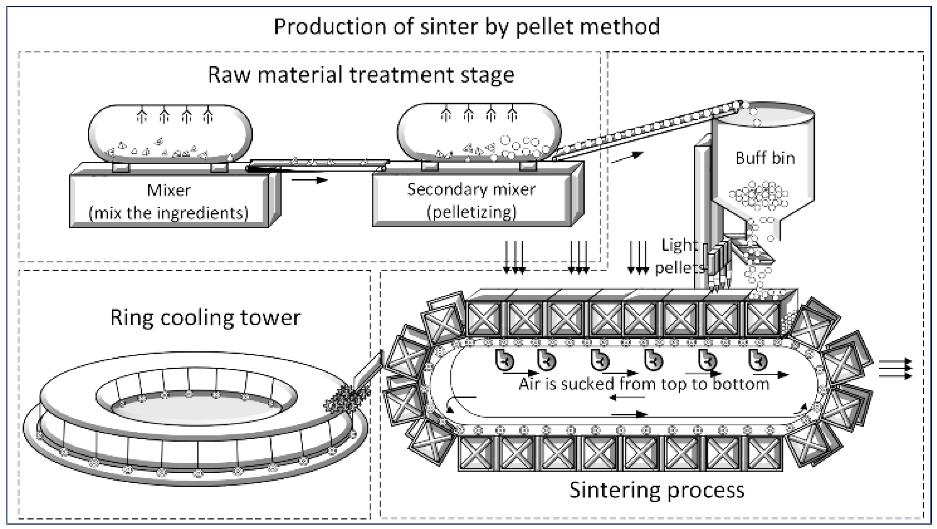
The iron-bearing kiln pellet method is a common method for producing pellet ore in iron production. The main equipment for the production of pellet ore by the iron-bearing kiln pellet production process consists of a sintering machine, a rotary kiln, and a ring cooler, with the sintering machine being the key equipment. The sinter trolley operates cyclically, periodically loading iron ore raw materials and unloading sinter ore. The process flow diagram of the iron-containing kiln pellet method is shown in Figure 1.
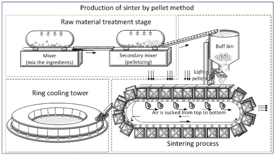
Figure 1.
Production of sinter by the pellet method.
During the sintering process in iron production, the sintering machine’s surface temperature can reach up to 1000 °C, and that of the trolley body can reach 45–50 °C due to the thermal conductivity of the trolley body. The sintering machine trolley axle must be subjected to severe static loads while operating in an extreme environment of high temperature and high torque [1]. The axle structure is subjected to higher torque forces at the turns, and the axle parts are highly susceptible to faults [2]. If sintering machine trolley axle faults are not detected or handled in a timely manner and the trolley continues to operate, the wheel of the trolley may fall off, which will cause the sintering machine trolley to jam and shut down, thus affecting the efficiency of the sintering production process [3,4]. Therefore, the automated monitoring of sintering machine trolley axle faults and providing faulty axle location information through the side plate number on the trolley to assist field maintenance personnel in troubleshooting are essential to ensure the safety and efficiency of sintering production.
Common methods for detecting axle faults include monitoring the temperature and vibration signals. When the axle fails, the wheel cannot operate normally, and the axle temperature will rise. By combining the temperature signal of the axle with the intelligent method, the fault of the axle can be identified and early prediction of faults can be performed. This can help maintenance teams to predict and repair axle faults in a timely manner [5,6,7]. When the axle is faulty, its vibration signal will contain clutter. By analyzing the vibration signal of the axle, the fault of the axle can be detected [8,9]. The use of machine learning for identifying and diagnosing axle faults has become more prevalent in recent years [10,11]. With the improvement in computer power, machine learning [12,13] and deep learning methods [14] have been applied to fault detection and early warning systems in the industrial field. By using machine learning methods to extract signal features, a variety of techniques can be combined to improve the accuracy of feature extraction [15,16].
The above studies mainly focus on axle fault detection in high-speed trains. However, the sintering machine trolley is a typical low-speed and full-load type of equipment. Due to the slow speed and the difficulty of heat accumulation, it is difficult to find faults in time by using temperature detection methods. Because of the cyclic operation of trolley wheels, it is difficult to install sensors in axles, which is not conducive to vibration signal acquisition. At present, the fault detection methods for axles are still based on manual detection, which is time-consuming, labor-intensive, and lacks automation.
Aiming to address the problem of axle fault detection in low-speed and full-load vehicles, this paper proposes a method to detect the axle faults of sintering machine trolleys based on the characteristics of wheel swing. Image processing technology and a deep learning object detection algorithm were used to determine the region of interest of the target. The frame difference method [17] was used to obtain the pixel differences between images of two adjacent wheels in the region of interest, and the difference was compared with the preset threshold to determine whether there was sintering machine trolley wheel swing so as to detect an axle fault. When an axle fault is detected, a deep learning algorithm is used to identify the number on the side plate corresponding to the wheel swing so as to locate the fault location. Finally, the fault detection system was constructed to provide information on the wheel swing fault detection and location, and to guide maintenance personnel in determining whether the axle is faulty, which can save on labor and improve work efficiency. The main contributions of this paper are summarized as follows:
- A computer vision method was combined with an object detection algorithm to determine the region of interest for the wheel, and wheel swing detection was completed in the region;
- This paper proposes a new method for axle fault detection in low-speed and heavy-load vehicles based on wheel swing and realizes a visual detection localization algorithm;
- An axle fault detection and location system was constructed based on the wheel swing detection and location algorithm. Real-time monitoring and early warning of wheel swing faults were realized.
The rest of the paper is outlined as follows: In Section 2, the axle fault-detection-related methods are mentioned. Section 3 describes the sinter machine trolley axle fault detection scheme. Section 4 describes the determination of the region of interest for the wheel and the algorithms for the detection and location of wheel swing faults. Section 5 discusses the axle fault detection methods and presents the axle fault detection system. The final section summarizes the innovativeness and limitations of the research work.
2. Related Work
In this section, we introduce the current mainstream application of artificial intelligence and vision methods to detect axle faults, as well as their applications in the sintering machine field. Methods for fault location and fault detection system are also mentioned.
2.1. Application of Artificial Intelligence and Vision Methods in Axle Fault Detection
Artificial intelligence techniques have been widely used in recent years in rail transportation and industrial production [18]. A large number of techniques combining traditional methods with artificial intelligence are being proposed in the industry.
Based on the YOLOv4 deep learning algorithm, Wang et al. [19] proposed a chain grate machine trolley side plate offset detection method. Based on convolutional neural networks with short-time Fourier transform, Pham et al. [20] proposed a new method for diagnosing bearing faults and their degradation level at variable speeds. By combining empirical wavelet transform and an improved self-attention-enhanced convolutional neural network, Dong et al. [21] proposed a new approach for bearing fault classification, which achieved 100% classification accuracy on three different bearing datasets. Based on axle box temperature data, using temperature data with artificial intelligence algorithms, Liu et al. [22] proposed predicting future axle box bearing temperatures by using time-series data of axle box bearing temperature-related variables as input for MLSTM models. Through the application of deep learning and multi-sensor data, Xue et al. [23] proposed a novel framework for motor bearing fault diagnosis from the perspectives of multi-transformation domain and multi-source data fusion, thereby negating the repercussions of rudimentary fusion on the precision of fault diagnosis. Dong et al. [24] proposed a framework for bearing fault diagnosis, aiming to improve the classification performance for complex bearing fault types. Oh et al. [25] proposed a denoising autoencoder and multiscale convolutional recurrent neural network, in which the denoising autoencoder accurately detects bearing defects in the same environment as the field bearing vibration signals, and the MS-CRNN was used to inspect and classify the defects with an accuracy of more than 90%. Using the YOLO architecture, Cui et al. [26] developed a fully convolutional network (FCN)-based defect detection method for noise barriers, named Skip Connection YOLO Detection Network (SCYNet). Based on the above network, a method for the automatic detection of noise barriers using UAV images was proposed.
To realize the real-time robust detection of moving vehicles in complex traffic scenes, San et al. [27] proposed a combined ViBe and inter-frame difference method, which can effectively remove the “ghosting” phenomenon that occurs in traditional methods. Based on the contour-processing inter-frame difference, Enze et al. [28] proposed an inter-frame difference optimization method for a production safety monitoring system for vehicles under different illumination environments. Based on the improved Canny operator with the adaptive frame difference method, Shi et al. [29] proposed a new method for the real-time monitoring of moving targets that can be used to detect moving axle faults.
2.2. Fault Location Technology
There are many classical algorithms for locating faults in axles [30]. Based on the mutual correlation analysis of accelerometer data from the left front and right rear of a vehicle axle, Li et al. [31] proposed a signal-based heavy-duty sway fault detection and localization system. The integration of deep learning with fault location is becoming increasingly close as deep learning algorithms continue to evolve. Based on the use of CNN and a convolutional autoencoder, Jana et al. [32] proposed a deep learning framework for time-invariant parameters that identifies the presence and type of fault from sensor data and provides the location of the faulty sensor. To solve the vehicle monitoring problem, Vetriselvi et al. [33] proposed an effective deep learning-based VLPNR model to identify and recognize alphanumeric characters in license plates to locate vehicles.
2.3. Current Status of Axle Detection Systems
In order to solve the axle fault problem, many axle detection systems have been proposed. Based on the application of inductive loop sensors, Marszalek et al. [34] proposed a technical solution for axle detection. Jorge et al. [35] presented an unsupervised methodology based on a wayside system and a stacked sparse autoencoder, which allows the detection and classification of out-of-roundness damage wheels based on dynamic responses induced on the track by crossing freight railway vehicles. Based on an axle-based acceleration methodology for rail track fault diagnosis, Shah et al. [36] proposed a prototype that is an automated and portable track recording of vehicles that is 87% more efficient than the traditional push-trolley-based TRV mechanism.
The rapid development of computer vision technology has provided a new opportunity for industrial automation. It has the advantages of non-contact easy installation and the ability to monitor the early fault visual characteristics using algorithms. It is being used more and more on the production site. Sintering machine trolley axle faults can cause wheel swing. This study aims to provide an early warning of axle faults by monitoring the swing characteristics of the wheels. By using a trained trolley wheel and side panel number detection model and the inter-frame difference method to monitor the characteristics of early wheel swing, advance warning of axle failure can be provided, and accidents can be avoided.
3. Main Scheme
3.1. Hardware Scheme of the Sintering Machine Axle Fault Detection System
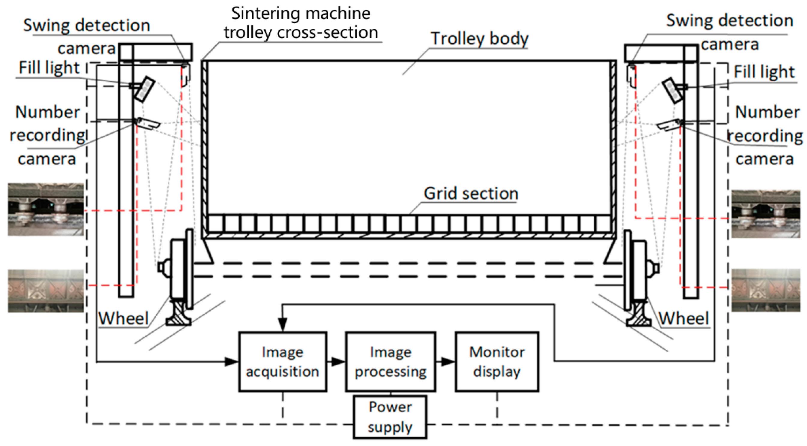
In this scheme, a fault detection system for the sintering machine axle based on wheel swing characteristics is proposed. The overall detection scheme for sintering machine trolley axle faults is shown in Figure 2. The support structures were built on both sides of the sintering machine trolley, and four industrial cameras were installed—two side plate number recording cameras and two wheel swing detection cameras. These can obtain real-time video images of the trolley wheel operation and record the side plate number. At the same time, the video frame images of the wheels were intercepted by fixed interval frames. The video images were transmitted to the server for algorithm processing. When the wheel swing fault is detected, the server sends the alarm information to the display terminal. The frame difference method requires high stability of illumination, so when the scene illumination is not good, it will affect the detection results. To solve this problem, we ensure consistent lighting conditions at the site by using a fill-light device.
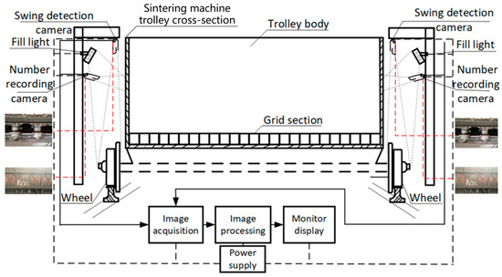
Figure 2.
Sintering machine axle fault detection scheme.
3.2. Implementation Scheme
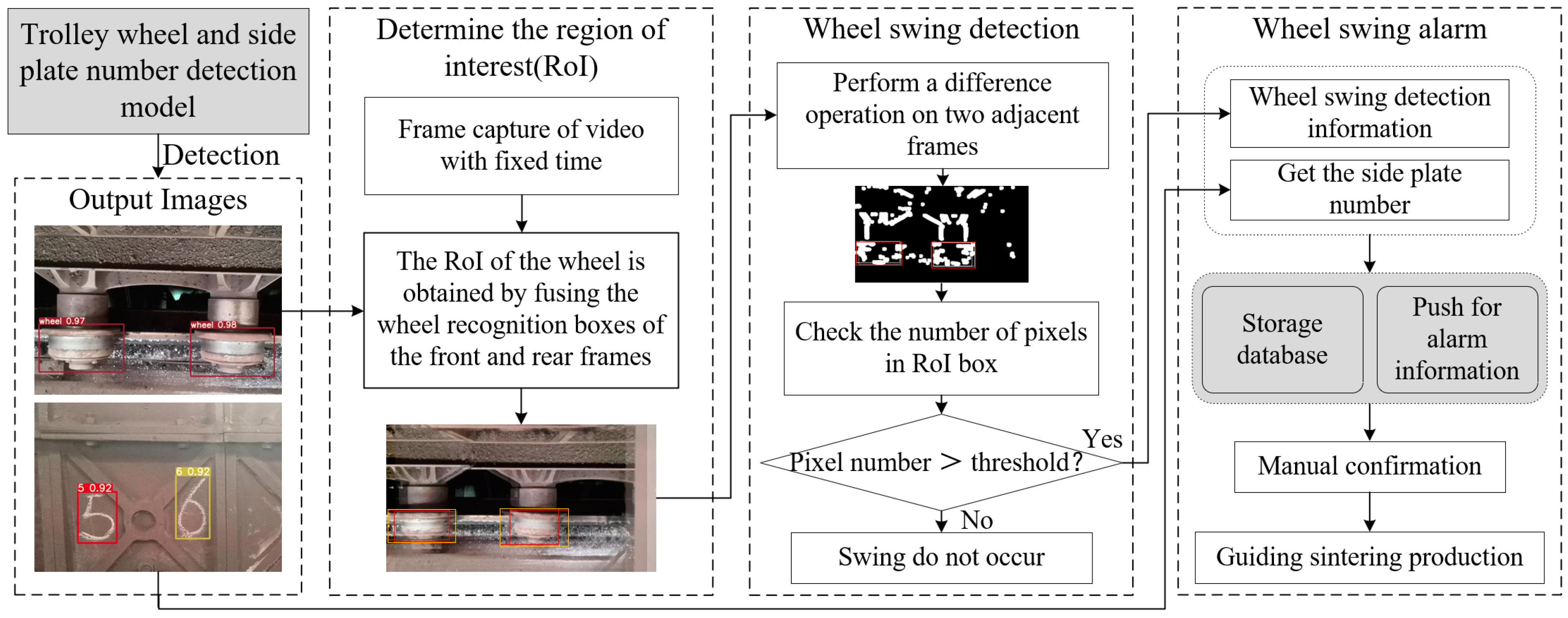
In this study, the YOLOv9 network, which performs relatively well on the trolley wheel and side plate number dataset, was selected as the basis for training to realize the detection of trolley wheels and side plate numbers. YOLOv9 incorporates the concept of programmable gradient information (PGI), which can provide complete input information for the target task to calculate objective functions so that reliable gradient information can be obtained to update network weights. It also utilizes the generalized efficient layer aggregation network (GELAN), which improves the parameter usage efficiency, accuracy, and inference speed [37]. It is more suitable to be applied in the scenario where real-time detection is required. The flow chart of the sintering machine trolley wheel swing detection is shown in Figure 3.
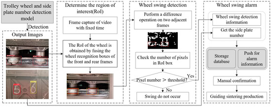
Figure 3.
The flow chart of the sintering machine trolley wheel swing detection method.
In the wheel fault detection stage, the trolley wheel and side plate number detection model was used to identify the wheel target in the video, and the coordinates of the wheel were obtained. In order to reduce the influence of the trolley vibration on the detection results, it is necessary to determine the region of interest detected by the frame difference method. According to the coordinate positions of the previous frame and the next frame of the same wheel, the region of interest for wheel swing detection was determined. In the region of interest of the wheel, the method of inter-frame difference was used to judge whether the wheel swings. When wheel swing was detected, a picture of the side plate number corresponding to the fault point was captured and recorded, and the side plate picture was sent to the trolley wheel and side plate number detection model for identification to locate the axle fault. Based on the above algorithm, the wheel swing detection system was constructed. The wheel swing detection system visually displays the fault information, including the fault time, fault location number, fault picture, etc. According to the alarm information provided by the detection system, field engineers can quickly go to the fault point for processing.
4. Materials and Methods
4.1. Wheel Position Detection
The training environment for the trolley wheel and side plate number detection model is as follows: Intel(R) Core(TM) i9-9900K CPU @3.60 GHz, running memory 64 GB, NVIDIA 3090 GPU*2, Ubuntu 18.04 operating system, deep learning framework using Pytorch1.7.0. Using the weight file obtained after training, the wheels of the trolley were identified. At the same time, the coordinate information of the wheel recognition boxes of the previous frame and the next frame were obtained.
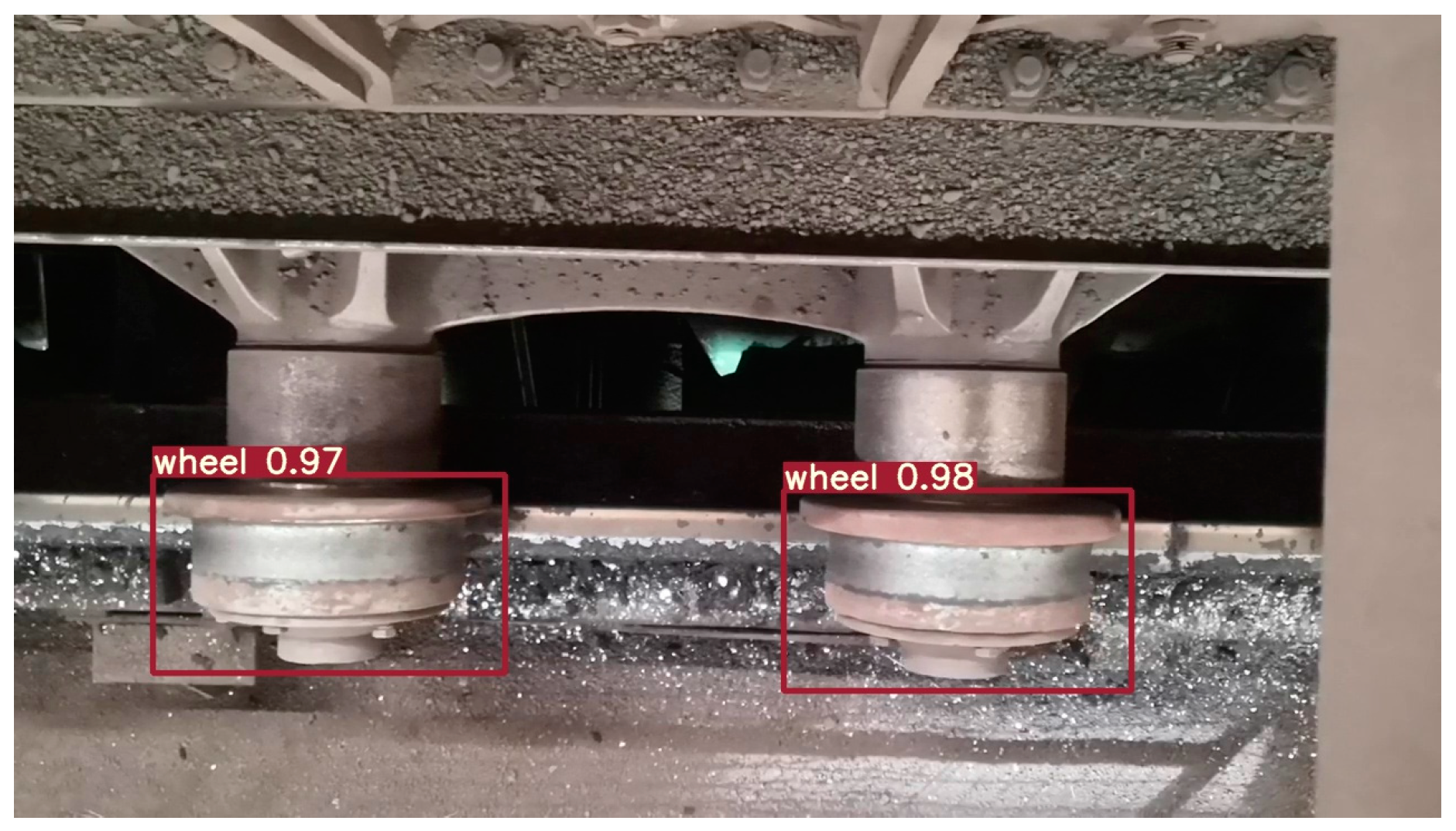
The wheel dataset was from the sintering production site of the Baotou Steel & Iron Group. The training set contains 424 wheel images. Data augmentation methods were used on the dataset to enhance the model’s robustness under different conditions while training the trolley wheel and side plate number detection model. Using the weight file obtained, the wheel of the trolley was identified. The recognition effect diagram of the wheel area is shown in Figure 4: the information displayed on the detection boxes in the figure indicates the class labels and confidence scores when detecting the wheels, where the confidence score is a decimal between 0 and 1, with values closer to 1 indicating that the model is more certain that the detection results are correct. The experimental results show that the average precision of wheel detection is 99.5%. By identifying the box of the wheel, the coordinate information of the wheel was determined for each frame. In the next step, the coordinate boxes of the previous frame and the next frame were fused into the region of interest.
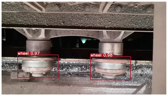
Figure 4.
Wheel area recognition results.
4.2. Determining the Wheel Region of Interest
In order to avoid interference from body vibration, the recognition box in the top view of the previous frame and the next frame of the same wheel were selected and fused into the region of interest (RoI) of the wheel. In the RoI, whether the wheel swings or not was determined.
The RoI calculation rule is as follows: For the same wheel, the upper-left and lower-right coordinates of the wheel identification box of the previous frame and the next frame were compared. The coordinates of the upper-left corner were taken as the minimum value, and the coordinates of the lower-right corner were taken as the maximum value. These two coordinates were used as the upper-left point and the lower-right point to construct a new coordinate box as the RoI for wheel identification. The green box in Figure 5a represents the identification box of the wheel that operated normally in the previous frame. The red box in Figure 5b represents the identification box of the wheel with a swing fault in the next frame. Figure 5c represents the interest region of wheel detection formed by the fusion of two identification boxes of the previous frame and the next frame, which is the orange part of the figure. In the RoI, the frame difference method was used for two adjacent images. The top-left coordinate calculation formula of the RoI is shown in Equation (1). The lower-right coordinate calculation formula of the RoI is shown in Equation (2).
where and are the coordinate information of the upper-left corner of the bounding boxes output by the trained wheel detection model when detecting the wheels, and both and are the coordinates of the lower-right corner of the bounding boxes.
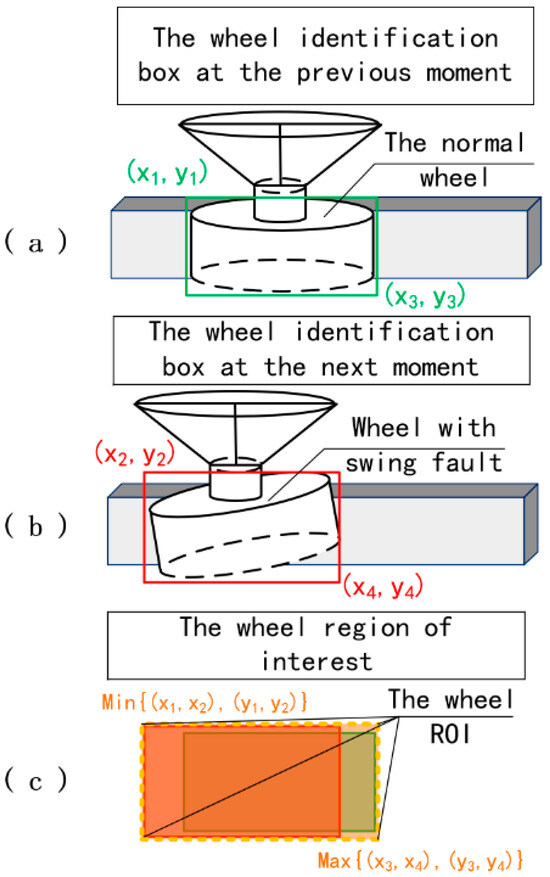
Figure 5.
Setting the wheel’s region of interest: (a) wheel identification at the previous moment, (b) wheel identification at the next moment, (c) wheel region of interest.
4.3. Wheel Swing Detection
This experiment was conducted in a Windows 10 environment. The inter-frame difference method and image processing algorithm were implemented on an AMD Ryzen 5 5600 H 3.30 GHz, 16 GB of RAM.
At the stage of wheel swing detection, the image obtained by the camera was processed by the above algorithm. The region of interest of the wheel was determined. The frame difference method was used in the identification box containing the RoI of the wheel. In the region of interest, the pixel difference between the previous frame and the next frame was compared. According to Equation (3), the angle of the forward wheel rotation in the image acquisition interval time can be obtained.
where is the angle at which the wheel rotates forward, is the interval time of image acquisition, is the linear velocity of the trolley, and is the radius of the wheel.
The trolley running speed at the site of the sintering machine trolley was roughly 0.03 m/s, and the frame rate of the camera image acquisition was 20 frames/s. Based on the running speed of the sintering machine trolley and the frame rate of the camera, an image was captured every 40 frames with an acquisition interval of 2 s in the task of detecting wheel swing using the frame difference method. According to Equation (3), the rotation angle of the wheel running in the direction of the track was about 21.6°. When the wheel swings, the algorithm can well detect the swing characteristics of the wheel.
The mathematical formula of the frame difference method is given as Equations (4) and (5):
In Equation (4), is the k frame image, and is the frame image. is the difference between the pixels of the two frames. In Equation (5), is the difference image after binarization, and the pixel value of the moving target is 255; otherwise, the value is 0. is the threshold selected by binarization, and its value can be appropriately selected according to the actual situation to meet the needs of the moving object detection in different scenes.
Checking the number of white pixels in the region of interest: If the number of pixels in the region of interest is less than the threshold set according to the actual production, it is judged that the wheel of the sintering machine trolley does not swing. If the number of white pixels is greater than the set threshold, it is judged that the wheel swings.
The setting rule of the threshold of the number of white pixels in the region of interest is as follows: By collecting 30 groups of normal wheel operation data, the number of white pixels obtained by the frame difference method in the region of interest under normal operation conditions was counted. By obtaining the maximum number of white pixels in normal operation and combining it with the experience of field workers, we selected 1.5 times the maximum number of white pixels in the normal operation group as the threshold to determine whether the wheel is swinging.
The axle fault detection result of the sintering machine as shown in Figure 6a is the image of the sintering machine running in the previous frame. Figure 6b shows the image of the sintering machine when the trolley is running in the later frame. Figure 6c shows the detection results obtained by the inter-frame difference method. Figure 6(I) shows the test results obtained when the left wheel and right wheel of the sintering machine trolley are in normal operation at the two frames before and after. In the figure, the number of pixels of the left and right wheels does not exceed the threshold, so it is determined that the wheels do not swing. Figure 6(II) shows the detection results where the left and right wheels of sintering machine trolley are in normal operation in the previous frame, and the left wheel of sintering machine trolley swings and the right wheel is in normal operation in the next frame. In the figure, the number of pixels in the RoI of the left wheel exceeds the threshold, and the left wheel is judged to be swinging. Figure 6(III) shows the detection results of a left wheel swing and a normal right wheel in the previous frame of the sintering machine trolley, and a normal left wheel and a right wheel swing in the next frame of the sintering machine trolley. In the figure, the number of pixels in the RoI of the left and right wheels exceeds the threshold, and it is determined that the left and right wheels swing. There is a positive correlation between the number of white pixels and the wheel swing angle; when the wheel swing angle becomes larger, the number of white pixels increases. In this paper, the number of white pixels exceeding the threshold is used to determine whether the wheel is swinging. In the wheel swing detection results, it can be seen that the larger the wheel swing detection angle, the greater the number of white pixels that will exceed the threshold, and the accuracy of wheel swing detection will be improved.
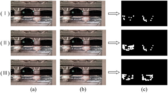
Figure 6.
The detection result diagram of the sintering machine trolley axle fault detection method: (a) previous frame of wheel images, (b) later frame of wheel images, (c) inter-frame differencing results.
This paper mainly lists three kinds of situations. Situation (I): The left and right wheels of the previous frame are normal (no swing), and the right wheel of the next frame swings and the left wheel is normal; Situation (II): The left and right wheels of the previous frame are normal (no swing), and the left wheel of the next frame swings and the right wheel is normal; Situation (III): The previous frame left wheel swings and right wheel is normal, and in the next frame, the right wheel swings and the left wheel is normal. A total of 75 tests were carried out on the field wheels under different running states, and the detection results are shown in Table 1. The experimental results show that the detection rate was 86.67% for swings of more than 1 degree and less than 2 degrees and 96.67% for swings of more than 2 degrees and less than 4 degrees, while the detection rate for swings of more than 4 degrees was 100%. The average detection rate was 93.33%. The method presented in this paper provides a possibility to replace the manual observation and detection of axle faults in production sites and can further guide industrial production.

Table 1.
The detection results of wheel swing.
The sinter trolley periodically loads raw materials and offloads sintered ore. During each cycle of the sintering machine operation, the trolley moves, and the wheels will be detected at least once. When faults become severe, they will be easier to detect. Multiple rounds of detection can further enhance the accuracy of detecting wheel swing faults that may not have been easily detected initially.
4.4. Swing Fault Location Algorithm
After the camera detected the wheel swing, the side plate number camera captured an image of the corresponding side plate at the fault location. This image was then sent to the trolley wheel and side plate number detection model for numerical recognition, which located the fault location of the axle based on the recognition results.
There were 610 images in the trolley side plate number dataset, consisting of categories 0 to 9. The trolley wheel and side plate number detection model was trained through these images and used to locate the faulty trolley. The training results showed an average precision of 99.2% in recognizing the side plate numbers of the trolley. Once the recognition results were obtained, the numbers were arranged and combined in the correct order to obtain the side plate numbers, which were then outputted.
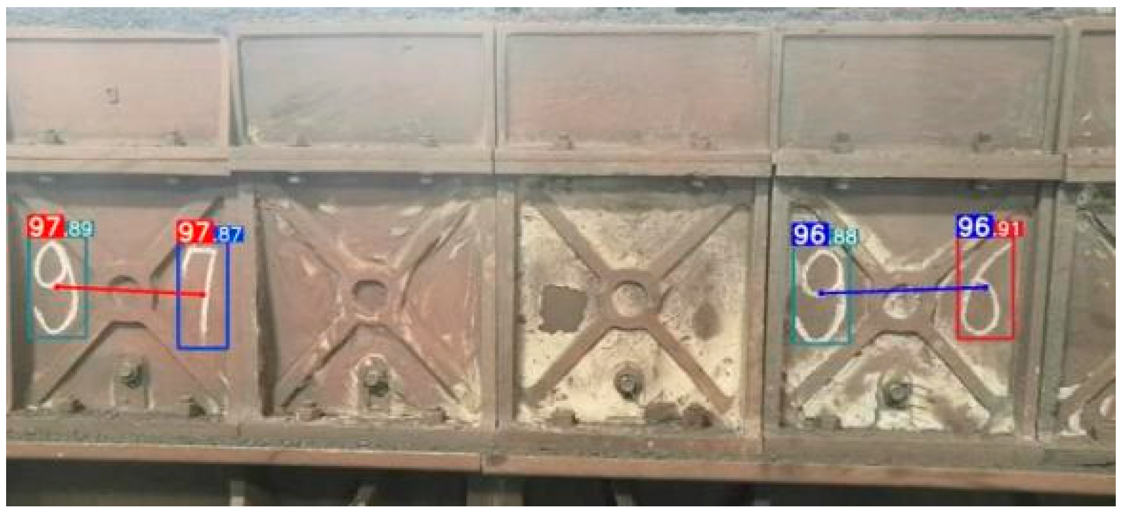
Upon observing the production site, it was discovered that the interval between numbers within the same group was smaller than that between numbers in different groups. Based on this observation, this paper proposes a method for determining group numbers. If the distance between two digits was smaller than the specified threshold, they were identified as a group of digits. Conversely, if the distance between two digits was greater than the specified threshold, they were identified as a different group of digits. Different groups of numbers were output as independent numbers, while the same group of numbers underwent digit place determination based on the x-coordinate value in the image coordinate system. Specifically, the digit place was higher for numbers with smaller x-coordinate values within the same group. Figure 7 shows a flow chart depicting the process of identifying and combining numbers. Figure 8 shows the recognition result of the side panel number. The number “96” and the number “97” in the figure are different groups of numbers, which can be easily recognized.
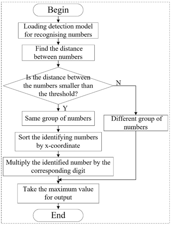
Figure 7.
The flow chart for determining the same group of numbers.
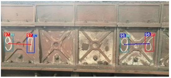
Figure 8.
The recognition results of side plate numbers.
5. Discussion of the Axle Fault Detection Method and System Construction
In the sintering process, the sintering machine trolley moves slowly at a speed of 0.03 m/s, and the speed of axle rotation is extremely low, which make it difficult for the vibration acquisition equipment to measure the fundamental frequency of the wheel operation. Acoustic emission analysis puts forward higher technical requirements for signal acquisition and identification. Due to the noisy environment of the sintering production site and the attenuation of the acoustic emission signal, it can be easily interfered with by environmental noise. In addition, due to the large number of trolley wheels, the additional installation of sensors and trackside acoustic device systems is costly and complex to realize. Due to the thermal conductivity of the sintering machine trolley body, the operating temperature of its wheels can reach 45~50 °C, and the temperature signals are also easily disturbed. Although axle fault detection is based on vibration, acoustic emission and temperature signals may be more efficient for the early detection of axle faults; however, this method is currently not suitable for the axle fault detection of sintering machine trolleys based on the actual conditions of sintering production. In this study, the wheel swing after the axle fault of a sintering trolley was taken as the detection feature based on the flexibility and non-contact characteristics of computer vision, and this was combined with the object detection algorithm and the frame difference method to realize the detection of sintering trolley axle faults under the conditions of low speed, full load, and temperature change.
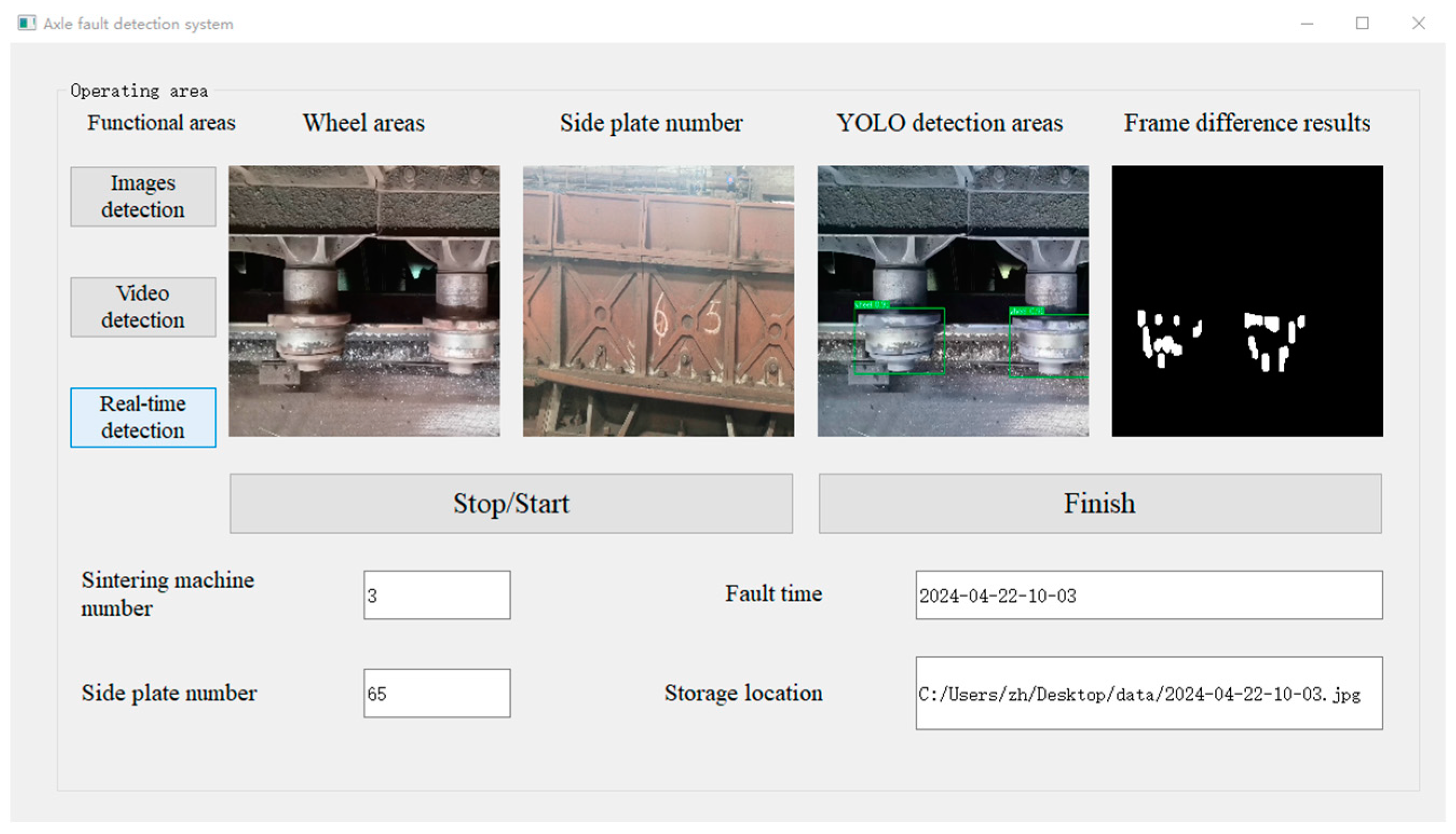
Based on the implementation of the axle fault detection and location algorithm, the axle fault detection system was constructed. In this system, the target wheels in the video were identified using the trained trolley wheel and side plate number detection model to obtain the wheel coordinates and to determine the RoI for wheel swing detection. Then, the frame difference method was applied to the region of interest to determine the difference between two frames of images. When wheel swing was detected, this system stored the fault alarm information in the database and sent it to staff in the field. The alarm information includes the number of the side plate corresponding to the fault location, the time of the fault, and the fault picture. The detection interface is shown in Figure 9. The video collected from the sintering plant was used to validate the axle fault detection system constructed in this research, which can effectively detect the wheel swing of the sinter trolley and identify the fault location.

Figure 9.
The sintering machine axle fault detection system.
6. Conclusions
Axle fault is a prevalent issue in sintering machine operation, which can significantly disrupt the entire sintering process if not addressed promptly. In this paper, a wheel swing detection algorithm based on computer vision is proposed for detecting wheel swing caused by axle faults. Firstly, the trolley wheel and side plate number detection model was trained on the constructed dataset of sintering machine trolley wheels and side plate numbers, and its average precision rate reached 99.2%; thus, the detection of sintering machine trolley wheels and side plate numbers was realized with relatively high precision. On this basis, the trained model was used to recognize the wheels and to determine the region of interest, and then the frame difference method was used in the region of interest to detect whether the wheel swings. The experimental results showed that the average detection rate of the method for wheel swing was 93.33%, which can be used as a basis for judging axle faults and to locate the trolleys where the axle faults occur according to the trolley side plate number and location algorithm. The axle fault detection system was constructed on this basis, which realized the real-time monitoring of axle faults. This system can effectively prevent the occurrence of sintering production accidents, reduce the consumption of human resources, and improve the stability of sintering production.
However, the frame difference method is sensitive to illumination changes and background interference, and its lighting conditions and threshold for judging wheel swing need to be adjusted according to the site conditions when applying it to other sintering production plants. In addition, in subsequent research, we will transform the wheel running videos into video feature sequences and further improve the accuracy of wheel swing detection by a deep learning model based on time series.
Author Contributions
Conceptualization, B.C. and Y.W.; methodology, B.C., H.Y. and Y.W.; validation, B.C., H.Y. and J.M.; formal analysis, Y.W.; resources, B.C. and Y.W.; data curation, J.M. and H.Z.; writing—original draft preparation, B.C.; writing—review and editing, B.C., H.Y. and Y.W.; visualization, B.C. and H.Z.; supervision, Y.W.; project administration, H.Y., J.M. and Y.W.; funding acquisition, B.C. and Y.W. All authors have read and agreed to the published version of the manuscript.
Funding
This research was supported by the Science and Technology Program of the Inner Mongolia Autonomous Region (grant no. 2021GG0045) and the Research Program of Science and Technology at Universities of the Inner Mongolia Autonomous Region (grant no. NJZY21400).
Data Availability Statement
The data presented in this study are available on request from the author at wym20017@imust.edu.cn.
Conflicts of Interest
All authors declare that they have no conflicts of interest affecting the research reported in this article.
References
- Gong, Y.H.; Wang, C.H.; Li, J.; Mahyuddin, M.N.; Seman, M.T.A. Application of deep learning in iron ore sintering process: A review. J. Iron Steel Res. Int. 2024, 31, 1033–1049. [Google Scholar] [CrossRef]
- Du, C.; Dutta, S.; Kurup, P.; Yu, T.; Wang, X. A review of railway infrastructure monitoring using fiber optic sensors. Sens. Actuators 2020, 303, 111728. [Google Scholar] [CrossRef]
- Shentsov, A.I.; Odintsov, A.A.; Svirin, E.B. Development of methods and technologies at the sinter plant. Metallurgist 2014, 58, 459–463. [Google Scholar] [CrossRef]
- Fernández-González, D.; Ruiz-Bustinza, Í.; Mochón, J.; González-Gasca, C.; Verdeja, L.F. Iron ore sintering: Process. Miner. Process. Extr. Metall. 2017, 38, 215–227. [Google Scholar] [CrossRef]
- Wang, B.; Liu, Y.; Zhang, B.; Huai, W. Analysis of the temperature characteristics of high-speed train bearings based on a dynamics model and thermal network method. Chin. J. Mech. Eng. 2022, 35, 104. [Google Scholar] [CrossRef]
- Yang, Z.; Wu, B.; Shao, J.; Lu, X.; Zhang, L.; Xu, Y.; Chen, G. Fault detection of high-speed train axle bearings based on a hybridized physical and data-driven temperature model. Mech. Syst. Signal Process. 2024, 208, 111037. [Google Scholar] [CrossRef]
- Yan, G.; Bai, Y.; Yu, C.; Yu, C. A multi-factor driven model for locomotive axle temperature prediction based on multi-stage feature engineering and deep learning framework. Machines 2022, 10, 759. [Google Scholar] [CrossRef]
- Zhao, L.; Yang, S.; Liu, Y. Weak fault feature extraction of axle box bearing based on pre-identification and singular value decomposition. Machines 2022, 10, 1213. [Google Scholar] [CrossRef]
- Sun, Q.; Chen, C.; Kemp, A.H.; Brooks, P. An on-board detection framework for polygon wear of railway wheel based on vibration acceleration of axle-box. Mech. Syst. Signal Process. 2021, 153, 107540. [Google Scholar] [CrossRef]
- Zhao, X.; Qin, Y.; He, C.; Jia, L. Intelligent fault identification for rolling element bearings in impulsive noise environments based on cyclic correntropy spectra and LSSVM. IEEE Access 2020, 8, 40925–40938. [Google Scholar] [CrossRef]
- Zhang, J.; Hu, X.; Zhong, X.; Zhou, H. Fault diagnosis of axle box bearing with acoustic signal based on chirplet transform and support vector machine. Shock Vib. 2022, 2022, 9868999. [Google Scholar] [CrossRef]
- Pedregosa, F.; Varoquaux, G.; Gramfort, A.; Michel, V.; Thirion, B.; Grisel, O.; Duchesnay, É. Scikit-Learn: Machine Learning in Python. J. Mach. Learn. Res. 2011, 12, 2825–2830. [Google Scholar]
- Zhang, J.M.; Harman, M.; Ma, L.; Liu, Y. Machine learning testing: Survey, landscapes and horizons. IEEE Trans. Softw. Eng. 2022, 48, 1–36. [Google Scholar] [CrossRef]
- Cao, H.; Shao, H.; Zhong, X.; Deng, Q.; Yang, X.; Xuan, J. Unsupervised domain-share CNN for machine fault transfer diagnosis from steady speeds to time-varying speeds. J. Manuf. Syst. 2022, 62, 186–198. [Google Scholar] [CrossRef]
- Chen, H.; Jiang, B.; Ding, S.X.; Huang, B. Data-driven fault diagnosis for traction systems in high-speed trains: A survey, challenges, and perspectives. IEEE Trans. Intell. Transp. Syst. 2020, 23, 1700–1716. [Google Scholar] [CrossRef]
- Li, W.; Zhong, X.; Shao, H.; Cai, B.; Yang, X. Multi-mode data augmentation and fault diagnosis of rotating machinery using modified ACGAN designed with new framework. Adv. Eng. Inf. 2022, 52, 101552. [Google Scholar] [CrossRef]
- He, H.; Ma, S.C.; Sun, L. Multi-moving target detection based on the combination of three frame difference algorithm and background difference algorithm. In Proceedings of the 2018 WRC Symposium on Advanced Robotics and Automation 2018, Beijing, China, 16 August 2018; pp. 141–146. [Google Scholar]
- Chen, H.; Jiang, B. A review of fault detection and diagnosis for the traction system in high-speed trains. IEEE Trans. Intell. Transp. Syst. 2019, 21, 450–465. [Google Scholar] [CrossRef]
- Wang, Y.; Li, Z.; Fang, L.; Li, Q. Offset detection of grate trolley’s side plate based on YOLOv4. J. Sens. 2021, 2021, 5552206. [Google Scholar] [CrossRef]
- Pham, M.T.; Kim, J.M.; Kim, C.H. Accurate bearing fault diagnosis under variable shaft speed using convolutional neural networks and vibration spectrogram. Appl. Sci. 2020, 10, 6385–6399. [Google Scholar] [CrossRef]
- Dong, Z.; Zhao, D.; Cui, L. An intelligent bearing fault diagnosis framework: One-dimensional improved self-attention-enhanced CNN and empirical wavelet transform. Nonlinear Dyn. 2024, 112, 6439–6459. [Google Scholar] [CrossRef]
- Liu, L.; Song, D.; Geng, Z.; Zheng, Z. A real-time fault early warning method for a high-speed emu axle box bearing. Sensors 2020, 20, 823. [Google Scholar] [CrossRef] [PubMed]
- Xue, Y.; Wen, C.; Wang, Z.; Liu, W.; Chen, G. A novel framework for motor bearing fault diagnosis based on multi-transformation domain and multi-source data. Knowl. -Based Syst. 2024, 283, 111205. [Google Scholar] [CrossRef]
- Dong, Z.; Zhao, D.; Cui, L. Non-negative wavelet matrix factorization-based bearing fault intelligent classification method. Meas. Sci. Technol. 2023, 34, 115013. [Google Scholar] [CrossRef]
- Oh, S.; Han, S.; Jeong, J. Multi-scale convolutional recurrent neural network for bearing fault detection in noisy manufacturing environments. Appl. Sci. 2021, 11, 3963. [Google Scholar] [CrossRef]
- Cui, J.; Qin, Y.; Wu, Y.; Shao, C.; Yang, H. Skip connection YOLO architecture for noise barrier defect detection using UAV-based images in high-speed railway. IEEE Trans. Intell. Transp. Syst. 2023, 24, 12180–12195. [Google Scholar] [CrossRef]
- Sun, W.; Du, H.; Ma, G.; Shi, S.; Zhang, X.; Wu, Y. Moving vehicle video detection combining ViBe and inter-frame difference. Int. J. Embed. Syst. 2020, 12, 371–379. [Google Scholar] [CrossRef]
- Enze, Y.; Miura, Y. Inter-frame differencing in training data for artificial intelligence: Contour processing for inter-frame differencing method. In Proceedings of the 2020 IEEE International Conference on Consumer Electronics—Taiwan 2020, Taiwan, China, 28–30 September 2020; pp. 1–2. [Google Scholar]
- Shi, G.; Suo, J.; Liu, C.; Wan, K.; Lv, X. Moving target detection algorithm in image sequences based on edge detection and frame difference. In Proceedings of the 2017 IEEE 3rd Information Technology and Mechatronics Engineering Conference 2017, Chongqing, China, 3–5 October 2017; pp. 740–744. [Google Scholar]
- Wu, G.; Yan, T.; Yang, G.; Chai, H.; Cao, C. A review on rolling bearing fault signal detection methods based on different sensors. Sensors 2022, 22, 8330. [Google Scholar] [CrossRef] [PubMed]
- Li, C.; Luo, S.; Cole, C.; Spiryagin, M.; Sun, Y. A signal-based fault detection and classification method for heavy haul wagons. Veh. Syst. Dyn. 2017, 55, 1807–1822. [Google Scholar] [CrossRef]
- Jana, D.; Patil, J.; Herkal, S.; Nagarajaiah, S.; Duenas-Osorio, L. CNN and Convolutional Autoencoder (CAE) based real-time sensor fault detection, localization, and correction. Mech. Syst. Signal Process. 2022, 169, 108723. [Google Scholar] [CrossRef]
- Vetriselvi, T.; Lydia, E.L.; Mohanty, S.N.; Alabdulkreem, E.; Al-Otaibi, S.; Al-Rasheed, A.; Mansour, R.F. Deep learning based license plate number recognition for smart cities. CMC Comput. Mater Contin. 2022, 70, 2049–2064. [Google Scholar] [CrossRef]
- Marszalek, Z.; Sroka, R.; Zeglen, T. Inductive loop for vehicle axle detection from first concepts to the system based on changes in the sensor impedance components. In Proceedings of the 2015 20th International Conference on Methods and Models in Automation and Robotics 2015, Miedzyzdroje, Poland, 24–27 August 2015; IEEE: Piscataway, NJ, USA, 2015; pp. 765–769. [Google Scholar]
- Jorge, T.; Magalhães, J.; Silva, R.; Guedes, A.; Ribeiro, D.; Vale, C.; Cury, A. Early identification of out-of-roundness damage wheels in railway freight vehicles using a wayside system and a stacked sparse autoencoder. Veh. Syst. Dyn. 2024, 1–26. [Google Scholar] [CrossRef]
- Shah, A.A.; Bhatti, N.A.; Dev, K.; Chowdhry, B.S. MUHAFIZ: IoT-based track recording vehicle for the damage analysis of the railway track. IEEE Internet Things J. 2021, 8, 9397–9406. [Google Scholar] [CrossRef]
- Wang, C.Y.; Yeh, I.H.; Liao, H.Y.M. YOLOv9: Learning What You Want to Learn Using Programmable Gradient Information. arXiv 2024, arXiv:2402.13616. [Google Scholar]


Disclaimer/Publisher’s Note: The statements, opinions and data contained in all publications are solely those of the individual author(s) and contributor(s) and not of MDPI and/or the editor(s). MDPI and/or the editor(s) disclaim responsibility for any injury to people or property resulting from any ideas, methods, instructions or products referred to in the content. |
© 2024 by the authors. Licensee MDPI, Basel, Switzerland. This article is an open access article distributed under the terms and conditions of the Creative Commons Attribution (CC BY) license (https://creativecommons.org/licenses/by/4.0/).