Article

The Effect of Cycloid Gear Wear on the Transmission Accuracy of the RV Reducer

by
Yourui Tao
1,
Huishan Liu
1,
Miaojie Wu
2,
Nanxian Zheng
1 and
Jiaxing Pei
3,*
1
College of Mechanical Engineering, Hebei University of Technology, Tianjin 300401, China
2
College of Mechanical Engineering, Tianjin University of Technology, Tianjin 300401, China
3
School of Mechanical and Equipment Engineering, Hebei University of Engineering, Handan 056038, China
*
Author to whom correspondence should be addressed.
Machines 2024, 12(8), 511; https://doi.org/10.3390/machines12080511
Submission received: 3 July 2024 / Revised: 22 July 2024 / Accepted: 26 July 2024 / Published: 29 July 2024
(This article belongs to the Special Issue Design and Manufacturing for Lightweight Components and Structures)

Abstract

:
The cycloid gear wear of RV reducers leads to the degradation of the industrial robots’ transmission accuracy, but the degradation law with respect to the wear volume is still unclear. In this paper, a method for determining transmission error (TE) through a combination of numerical and simulation analysis is proposed. The wear model of cycloid gear was ascertained based on the theory of Archard. Then, the full rigid body and rigid–flexible coupling model of RV reducers were established using the multibody dynamics theory. Finally, the static transmission error (STE) and dynamic transmission error (DTE) were investigated. The results show that as working hours increase, the cycloid gear wear volume increases, and transmission accuracy deteriorates, but the rate tends to slow down.

1. Introduction

In industrial robots, RV reducers are widely used due to large reduction ratios, high transmission accuracy, and compact design [1,2,3,4,5,6]. With the rapid development of robots in various fields like industry and healthcare, technological requirements have become more stringent, such as more accurate positioning and higher reliability [7]. Consequently, there are higher expectations for the behavior of RV reducers, especially in terms of transmission accuracy, which is closely tied to the positioning accuracy and reliability of robots.
The transmission error (TE) is an important performance indicator [8,9]. TEs can be classified into static transmission error (STE) and dynamic transmission error (DTE). STE is generated due to machining and installation under no load. DTE is formed due to deformation or friction during motion under load. Given the research on TE, scholars have focused on modeling, analysis, and optimization. For example, He and Shan [10] used the dynamic substructure approach to accurately develop a model of RV reducer’s TE. Xu et al. [11] proposed the concept of optimal measurement speed to accurately calculate TE. Based on such studies, Li et al. [12] developed a model of the cycloid pinwheel transmission and examined how cycloid gear manufacturing errors affected transmission accuracy. Zhang et al. [13] accurately simulated the tooth profile errors of involute gears and effectively predicted the transmission accuracy of the drive system. Han and Guo [14] comprehensively considered various factors and analyzed the global sensitivity of the RV reducer’s TE to identify the largest effect. Nowadays, with the development of technology, more and more scholars have built virtual prototype models of RV reducers for research. Jin et al. [15] used software to develop a model of the RV reducer and performed multibody dynamic simulations to explore parameters influencing the RV reducer’s TE. Zhang et al. [16] established the rigid–flexible coupling model to study the impact of gear clearance variation in TE. Li et al. [17] developed a lumped parameter dynamic model for the RV reducer and studied the effects of machining errors, assembly errors, and bearing clearance on transmission accuracy. Additionally, several studies have focused on reducing TE. Ren et al. [18] reduced TE by designing various tooth shape correction clearance curves. Jia et al. [19] reduced peak-to-peak TE by compensating for conjugation. Bruyere et al. [20] derived the optimal tooth correction formula based on the analysis of spur and helical gears to minimize TEs. In conclusion, many studies have been performed on transmission accuracy, with some encouraging findings, but none of the above studies have considered the degradation of transmission accuracy with time.
However, studies have shown that wear affects backlash accuracy, which further affects the accuracy of the robot [3]. Similarly, the gradual wear of the cycloid gear over time leads to a degradation in transmission accuracy. Therefore, numerous investigations have been conducted by researchers on wear. Archard [21] derived a mathematical model to quantify the wear volume, and numerous investigations make use of the Archard wear model. In accordance with this model, Bajpai et al. [22] predicted the wear volume on tooth surfaces using a gear contact force model based on finite elements. Shen et al. [23] combined finite element theory with numerical simulation methods to simulate the complex nonlinear wear process. Considering the impact of parameters on wear, Tunalioglu and Tuc [24] determined the effects of various torques and motor speeds on wear volume theoretically and verified the results experimentally. Brandão et al. [25] conducted wear tests to investigate the impact of contact stress, basestock, and particular film thickness on spur gear wear. To investigate material wear under real operating conditions, Mirparizi et al. [26] examined the nonlinear thermoelasticity of solids under mechanical and thermal loading. They also developed a nonlinear iterative finite element algorithm and analyzed finite strains resulting from impact loading [27].
In the above research, transmission accuracy and gear wear were given separately without considering the coupling relationship. Although Zhang et al. [28] explored the deterioration of TE with wear accumulation, the relationship remained unclarified. They did not clearly state the relationship between the wear, the working time of the reducer, and the transmission error. Additionally, the reducer’s load was assumed to be a constant torque, which does not align with real working conditions. The law governing the degradation of accuracy due to cycloid gear wear is not clear. Therefore, it is necessary to clarify the law of the transmission accuracy degradation caused by cycloid gear wear.
To investigate the effect of cycloid gear wear volume on the RV reducer’s transmission accuracy, the method for predicting transmission accuracy degradation through a combination of numerical and simulation analysis is proposed. Based on the RV reducer’s transmission principle, the cycloid gear wear is first determined. Next, the full rigid body and rigid–flexible coupled models are established using the multibody dynamics theory. Finally, the STE and DTE of the fully rigid body model and the STE of the rigid–flexible coupled models are discussed.

2. Wear Model in Cycloid Gear

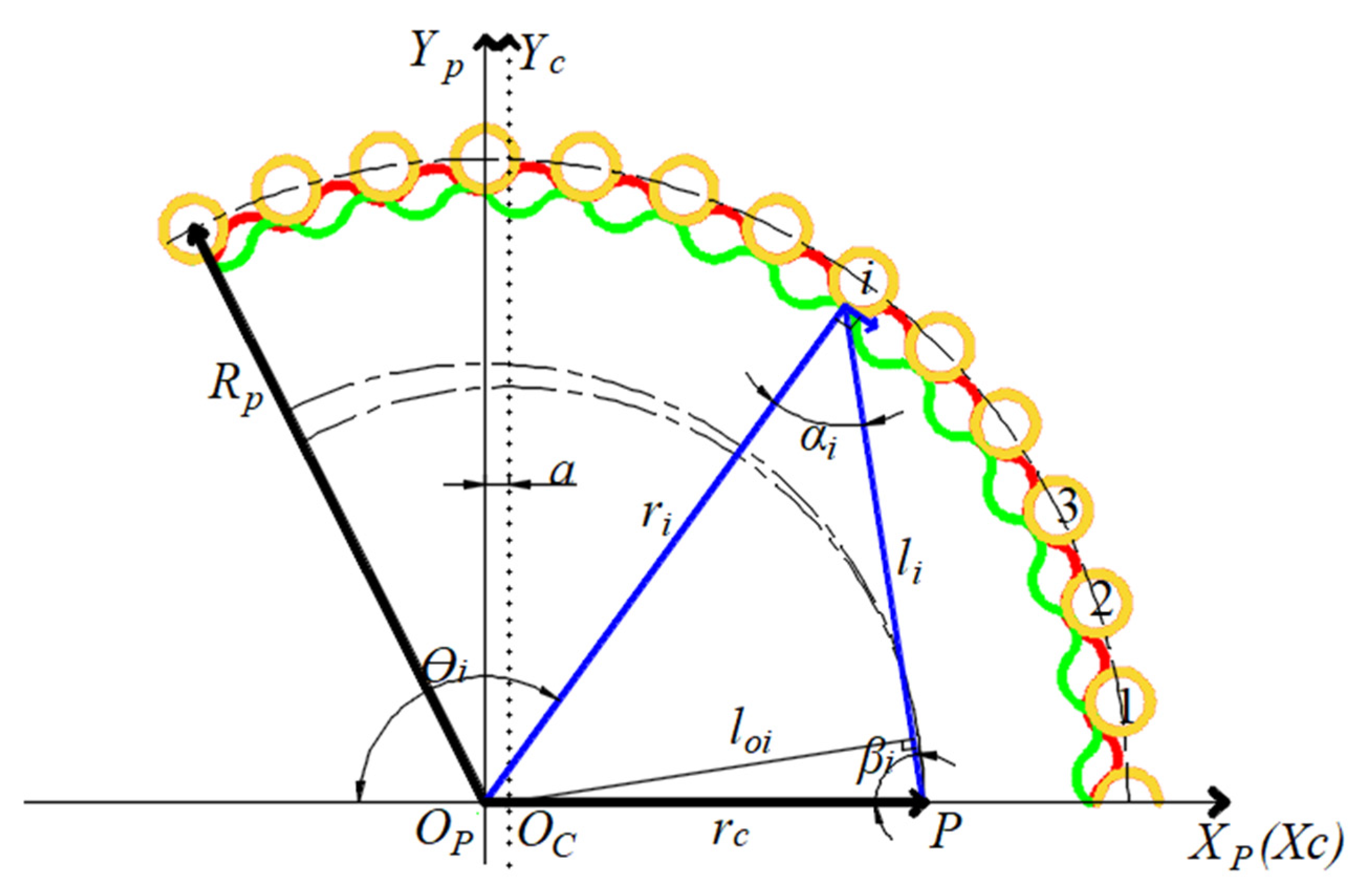
2.1. Tooth Profile of Cycloid Pinwheel Transmission

Figure 1 displays the RV reducer’s structure. It is made up of a high-speed planetary transmission and a low-speed cycloid pinwheel transmission. The transmission principle is as follows: the motor’s power is sent to the input shaft, which meshes and drives the planetary gear to accomplish the first stage of transmission. As the planetary gear and the crankshaft are fixed through splines, the crankshaft rotates with the planetary gear and drives the cycloid gears, moving eccentrically. Due to the meshing effect, the cycloid gears rotate around the pinwheel’s axis. As a result, the motion of the cycloid gears is transmitted to the output shaft by the crankshaft, achieving a second-stage transmission. Research has proven that the second-stage cycloid pinwheel transmission mainly affects the transmission accuracy of the RV reducer; thus, this paper focuses on the cycloid pinwheel transmission [10,29].
In accordance with the features of the cycloid pinwheel meshing [6], Figure 2 displays the tooth profile of the cycloid pinwheel transmission [28].
In Figure 2, XₚOₚYₚ and XCOcYc are the static coordinates axes of the pinwheel and cycloid gear, respectively, and P denotes the instantaneous velocity center of the cycloid pinwheel transmission. Op, Oc are the pinwheel and cycloid gear centers, respectively, θi depicts the meshing angle of rotation, αi represents the contact force angle, and βi is the normal angle.
The angular relationship in Figure 2 can be derived as follows [30]:
α i = tan 1 ( a Z p sin φ i R p a Z p cos φ i ) φ i = ϕ i 2 n π i H , n = 1 , 2 , 3 Z p γ i = mod ( 2 n π Z p ϕ i , π ) β i = π γ i α i
where γi is the pin position vector’s azimuth, φi represents the azimuth of the cycloid gear’s contact point, ϕi denotes the original angle of the crank. Rₚ represents the pin radius, a represents the eccentric distance of the crank, Zₚ denotes the cycloid gear’s tooth count, and iH depicts the transmission ratio.
The length relationship in Figure 2 can be expressed as follows:
l i = r c cos β i + r c sin β i tan α i
where rc is the cycloid gear’s base circle radius.
Based on (1) and (2), the cycloid gear’s standardized tooth profile is depicted using the following:
x = R p R r p 1 + K 1   2 2 K 1 cos ( θ ) 0.5 cos ( θ Z p Z c θ ) a K 1 R r p 1 + K 1   2 2 K 1 cos ( θ ) 0.5 cos ( Z p Z c θ ) y = R p R r p 1 + K 1   2 2 K 1 cos ( θ ) 0.5 sin ( θ Z p Z c θ ) + a K 1 R r p 1 + K 1   2 2 K 1 cos ( θ ) 0.5 sin ( Z p Z c θ )
where Rₚ represents the pin radius and Rrp is the radius of needle teeth. ZC denotes the number of pinwheels. K1 represents the short amplitude coefficient and can thus be calculated using the following:
K 1 = a Z p R p

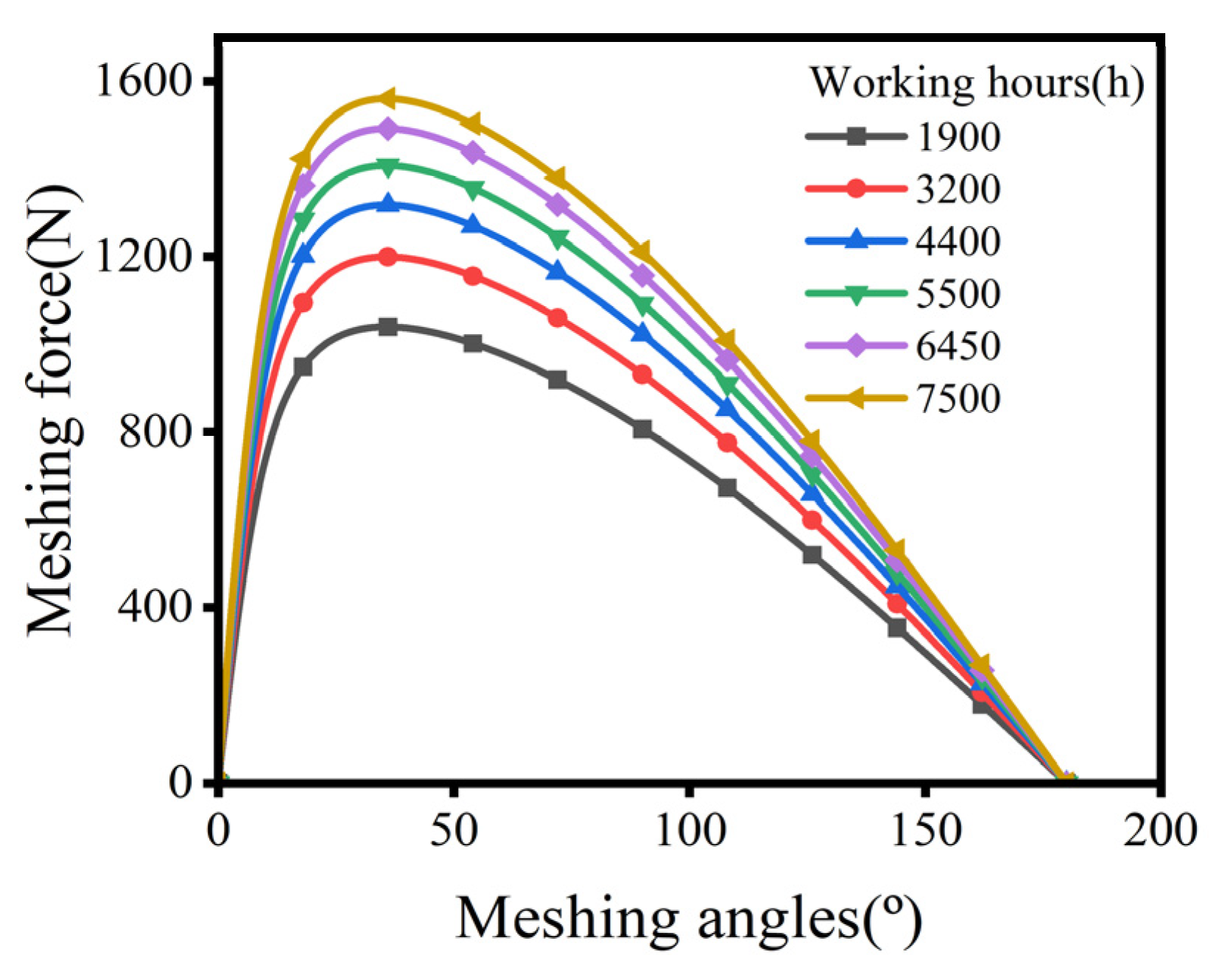
2.2. Meshing Force of the Cycloid Gear

In the cycloid pinwheel transmission, the meshing force of the cycloid gear is proportional to the amount of deformation [31]. The cycloid pinwheel transmission can be approximated as a Hertz contact [32], and the deformation in the normal direction can be defined as follows:
δ i = l i l max δ max = sin ϕ i 1 + K 1   2 + 2 K 1 cos ϕ i δ max
The deformation at the point of maximum contact force δmax can be defined as follows:
δ max = 2 F max π B [ 1 μ 1 2 E 1 ( 1 3 + ln 4 ρ c ) + 1 μ 2 2 E 2 ( 1 3 + ln 4 R r p c )
c = 4.99 × 10 3 ( 1 μ 1 2 E 1 + 1 μ 2 2 E 2 ) F max B ρ R r p ρ + R r p
where ρ represents the curvature’s radius and B represents the cycloid gear’s effective tooth width. E1, μ1 are the elasticity modulus and poison’s ratio of the cycloid gear, and E2, μ2 are the pinwheel’s corresponding values.
The pinwheel’s initial maximum contact force can be expressed as follows:
F max 0 = 2.2 T K 1 Z c R r p
where T is the load torque.
If pinwheels numbered m to n participate in meshing simultaneously, the maximum contact force can be formulated as follows:
F max = 0.55 T i = m i = n l i 2 l max
Then, the normal force can be defined as shown below:
F i = F max δ i δ max
A flowchart for solving the maximum contact force is presented in Figure 3.

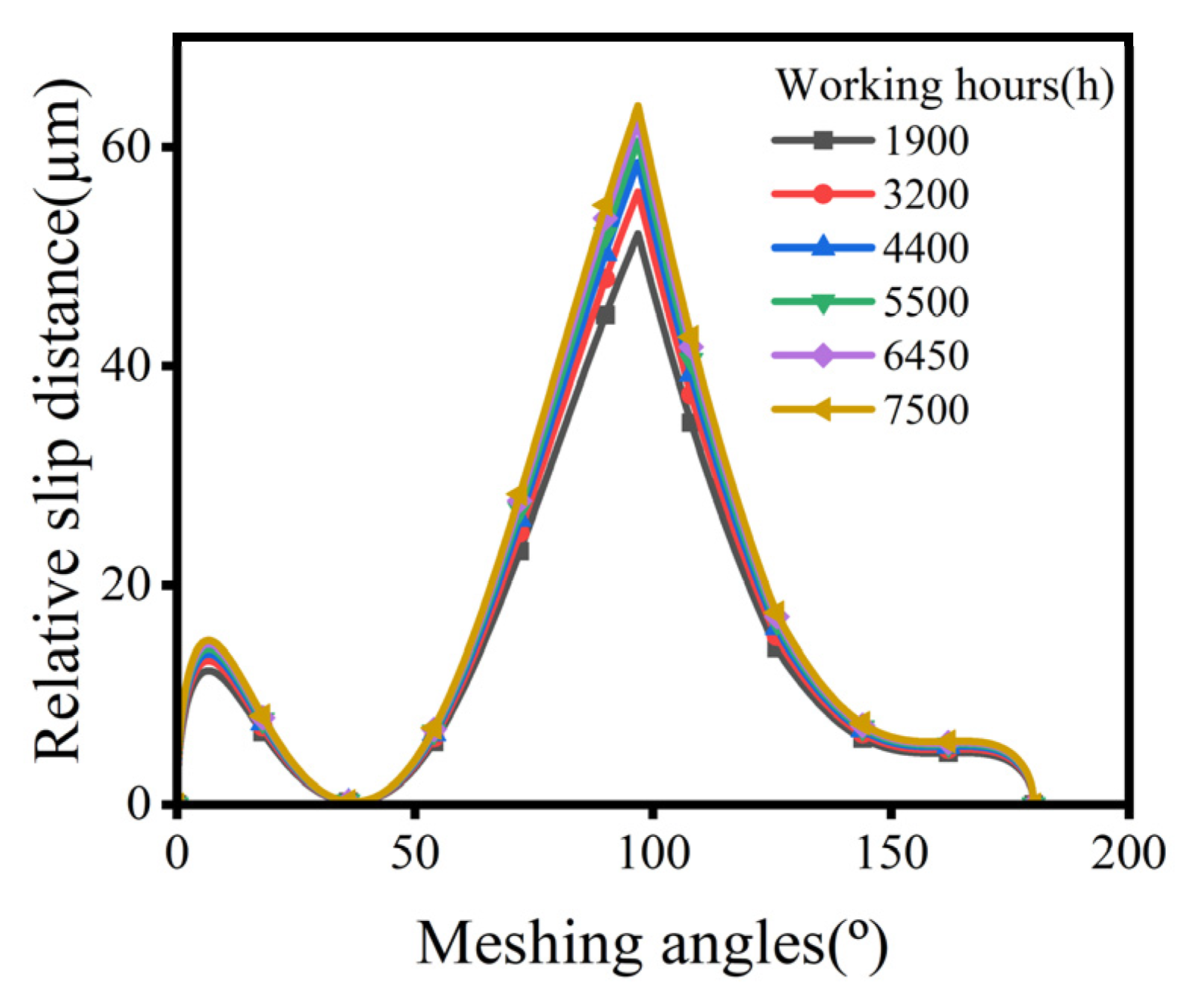
2.3. Wear Volume of the Cycloid Gear Tooth Profile

The cycloid pinwheel tooth profile meshing can be equivalent to two cylinders contacting at the meshing point, and the contact half-width can be calculated as follows [33]:
a H = 4 F i R π B E
where R* represents the equivalent radius of curvature and E* represents the equivalent elastic modulus.
1 R = 1 R 1 + 1 R 2
1 E = 1 μ 1 2 E 1 + 1 μ 2 2 E 2
where R1, R2 stand for the pinwheel’s and the cycloid gear’s radius of curvature, respectively.
The tangential velocity of the cycloid gear at the point of contact can be obtained as follows:
μ 1 = ω r i  
The tangential velocity of the pinwheel at the point of contact can be deduced from the following:
μ 2 = 1 i H ω l i
The relative sliding distance can, therefore, be found using the following [34]:
S = 2 a H ( 1 μ 1 cos α i μ 2 )
The RV reducer’s working time is t, the rotational speed is n1, and the degree of overlap is εa; then, the total friction distance during operation can be calculated using the following:
X = S n 1 t ε a
The average contact pressure P at any engagement point can be expressed as follows:
P = F i 2 a H B
The Archard model is utilized to compute tooth wear and can be obtained as follows:
V S = k W H
where V denotes the wear volume, k stands for the wear coefficient, S represents the sliding distance between different contact surfaces, W is the normal load, and H denotes the surface hardness.
The volume of wear can be expressed as follows [35]:
h q = k X P
where k = 1 × 10 13 [36].

3. TE Models Considering Wear

The RV reducer consists of planetary gear transmission and cycloidal pin gear transmission. The transmission error of the planetary gear primarily considers the axial and radial position errors of the planetary gears. The cycloidal pin gear system mainly involves the meshing errors between the cycloidal wheel and the pin gear. The transmission error of the RV reducer mainly arises from the geometric errors and manufacturing errors of the cycloidal pin gear system.
These errors lead to a discrepancy between the output shaft’s theoretical and actual angles, commonly referred to as transmission error. It can be defined as follows:
Δ θ = θ c a θ s i H
where θca denotes the output shaft’s actual rotation angle, and θs is the input shaft angle.
According to the value of load torque, TEs can be classified into STE and DTE. STE is generated due to machining and installation under no load. It can be expressed as follows:
Δ θ 1 = θ c a   1 θ s i H
DTE is formed due to deformation or friction during motion under load. It can be defined as follows:
Δ θ 2 = θ c a   2 θ s i H
To clarify the impact of cycloid gear wear on transmission accuracy, finite element software, and multibody dynamic software are utilized to develop the RV reducer’s dynamic model. The output shaft’s actual rotation angle and transmission accuracy degradation are then evaluated. Based on the results, the law between the cycloid gear wear and the RV reducer’s transmission accuracy is investigated. In this section, a rigid body model is developed with a focus on computational efficiency. Furthermore, to accurately describe the motion of the RV reducer and validate the rigid body model’s applicability, a rigid–flexible coupling model was also developed.

3.1. The Wear Model of Cycloid Gear

Numerical simulation can be used to generate the tooth profile of the wear model, as shown in (24).
x = ( R p + Δ r p ) ( R r p + Δ r r p ) 1 + K 1   2 2 K 1 cos ( θ ) 0.5 cos ( θ Z P Z C θ ) a K 1 ( R r p + Δ r r p ) 1 + K 1   2 2 K 1 cos ( θ ) 0.5 cos ( Z P Z C θ ) y = ( R p + Δ r p ) ( R r p + Δ r r p ) 1 + K 1   2 2 K 1 cos ( θ ) 0.5 sin ( θ Z P Z C θ ) + a K 1 ( R r p + Δ r r p ) 1 + K 1   2 2 K 1 cos ( θ ) 0.5 sin ( Z P Z C θ )
where Δrrp refers to the cycloid gear’s wear volume, Δrp = 0.
Table 1 shows the RV reducer’s fundamental parameters, such as the pin tooth radius and the number of teeth, which are used to calculate the wear volume of the cycloid gear. Additionally, the degree of overlap requires a formula for accurate calculation. However, to simplify the problem, it is assumed to be 1.3 [37].
The model without wear and the model with a wear volume of 60 μm are presented in Figure 4. The wear volume of the tooth profile varies at different meshing angles. Considering the significance of transmission accuracy, the maximum wear volume is taken for conservative TE analysis. After that, the tooth profile data are imported into the modeling software.

3.2. Full Rigid Body Model

The simulation modeling process is thus conducted with a wear volume of 10 μm on the cycloid gear. The previously unworn cycloid gears are replaced with the worn ones. After that, the solid model is imported into software, and each part of the material’s attributes needs to be defined, as listed in Table 2.
The material properties of the parts are correctly assigned, and the unit is set to MMKS. The constraints in Table 3 are intended to ensure that the parts are attached in the right way. The contact forces based on impact functions are utilized to simulate the interaction forces between gears, including elastic and damping forces [38]. Figure 5 shows the RV reducer’s mechanism.

3.3. Rigid–Flexible Coupling Model

High-precision modeling is essential to accurately determine the TE, so a rigid–flexible coupling model was developed. In the first stage of transmission, the planetary gear rotated faster and bore less torque, making local deformation relatively negligible. Due to the calculating efficiency, only the cycloid gear in the second-stage transmission was treated as a flexible body in which the elastic deformation could not be neglected. To mesh the cycloid gear, the 3D-tetramesh was selected.
Given the principle of motion of the RV reducer, a rigid point is established at the geometric center of the two cycloid gears, respectively, which coincides with the center of rotation. The center of rotation is rigidly connected to the surface nodes of each gear hole, and the cycloid gear rotation is achieved by releasing the Z-axis rotational degree of freedom. Figure 6 displays the finite element model. Then, the respective model center file (.MNF file) is generated, replacing the rigid body with the flexible body; thus, the rigid–flexible coupling model was established.

4. Results and Discussions

4.1. The Wear Volume on the Cycloid Gear Tooth Profile

With an input angular velocity of 9000°/s and a load torque of 412 Nm, Figure 7 shows the cycloid gear’s radius of curvature curve at different meshing angles. Around the meshing angle of 35°, the radius of curvature changed drastically due to the concave-convex transition of the tooth profile.
Figure 8 illustrates the impact of working hours on the meshing force. It shows that as the working hours increase, the meshing force increases, but it increments, and the quantity of meshing tooth pairs decreases.
Figure 9 presents the distribution of the relative slip distance for a single pair of meshing teeth along the tooth profile. The relative sliding distance approximates zero around a meshing angle of 35° due to the drastic change in curvature radius and the profile of the cycloidal gear approximating a half-plane. Additionally, two wear peaks appear around the meshing angle of 6° and 100°, which may be due to the higher linear speed of the pin gear or the larger contact half-width. The relative slip distances at different meshing angles rose unevenly with increasing working hours, implying that various positions of the tooth profile have different sensitivities to wear.
The wear volume along the cycloid gear’s tooth profile at different working hours is shown in Figure 10. The product of the wear coefficient and average contact pressure had a minor impact on the wear volume calculated by (20). The shape of the wear volume curve resembled that of the relative slip distance, varying at different meshing angles. Considering the significance of transmission accuracy, the subsequent calculations used the maximum wear volume from six simulations, which were 10, 20, 30, 40, 50, and 60 μm, respectively.

4.2. Effects of the Cycloid Gear’s Flexibility and Output Shaft’s Load on the TE

Transmission accuracy is significantly influenced by the characteristics of the transmission structure, such as the load on the output shaft and the cycloid gear’s flexibility. The study of TE at wear volumes of 10, 20, 30, 40, 50, and 60 μm, with different parameters, was conducted using the dynamic model. Due to space limitations, only the study of TE at a wear volume of 10 µm is shown in Section 4.2.
The input shaft speed, which powers the RV reducer, is set to 9000d × time × step (time, 0, 0, 0.1, 1). In Figure 11, the input and output speeds are displayed. The angular velocity of the input shaft fluctuates from 0 to 0.1 s and then stabilizes at 9000°/s from 0.1 s. The output shaft also reaches a stable speed, varying up and down around 111°/s from 0.1 s, satisfying the transmission relation. According to (21), the TE from 0.1 to 0.8 s can be determined, as shown in Figure 12. Its average value is 0.5351′.
To simulate the working conditions more accurately, a sinusoidal load torque was applied to the model [39], as shown in Figure 13.
Figure 14 displays the input and output speeds. Figure 15 illustrates the TE curve, with an average value of 0.2278′. In addition, the shape of the TE curve was affected by the load, mapping the sinusoidal pattern. The cycle of TE was approximately 0.3 s, with significant fluctuations reaching around 5.2′, which may be caused by the instability of the load.
Because the mechanical system was not an absolute rigid body in engineering, the flexible modeling of the worn cycloid gear was generated, replacing the original rigid body. As shown in Figure 16, the input and output speeds are depicted.
The STE curve is seen in Figure 17, with an average value of 1.7342′. In addition, the TE’s variation is clearly diminished, with the maximum value being approximately 7.5′.

4.3. Effects of Wear Volumes on the TE

Since the working hours were closer to the actual representation, the following figures show an investigation into the TE as the working hours changed.

4.3.1. The STE and DTE of the Full Rigid Model

Figure 18 depicts the rigid body’s STE and DTE. The STE initially increased with time, occasionally experiencing slight decreases, but ultimately continued to increase. The largest value reached 4.11′ at a working time of 6450 h. In addition, the DTE under sinusoidal load reached the largest value of 3.51′ at a working time of 6450 h. Although both exhibited a two-stage degradation process, the average value of the DTE was lower, likely because the gap was compensated with the load. Furthermore, the DTE fluctuated more as the load was unstable.

4.3.2. The STE of the Rigid–Flexible Coupling Model

To build a more accurate model of the RV reducer, the cycloid gear was regarded as a flexible body. The TE is presented in Figure 19a, and the largest value reached 6.77′ at a working time of 7500 h. Figure 19b compares the STEs of the rigid model and the rigid–flexible coupling model. It was found that even though the two have a similar trend, the TE increased with the growth of working time in general. But, under the rigid–flexible coupling model, the TE did not exhibit a two-stage degradation process. And the largest value reached 6.77′. Upon analysis, the rigid body model only considered the motion equations of the components, reflecting the movement relationships between them. Conversely, the rigid–flexible coupling model accounted for the elastic deformation and internal stress distribution of the components and could, therefore, more precisely simulate the interactions between contact surfaces. The computer runtime for the rigid body and rigid–flexible coupling model was 0 h 12 m 52 s and 1 h 56 m 33 s, respectively, based on the hardware (Intel core I5 12,400 CPU, DDR4 16G RAM) and software (ADAMS VIEW 2020).

5. Conclusions

The RV reducer is a crucial component in industrial robots, and its transmission accuracy affects the robot’s positioning accuracy. In this work, the cycloid gear’s wear volume was constructed using the Archard theory; then, the full rigid body and rigid–flexible-coupled models were established using multibody dynamics. Finally, the STE and DTE of the fully rigid body and the STE of the rigid–flexible coupled model were discussed. The following conclusions were obtained from the research:
(1)
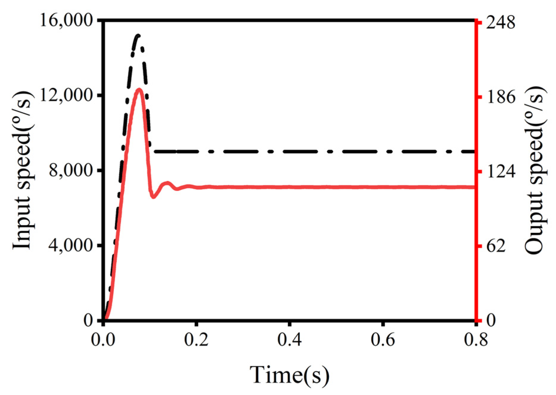
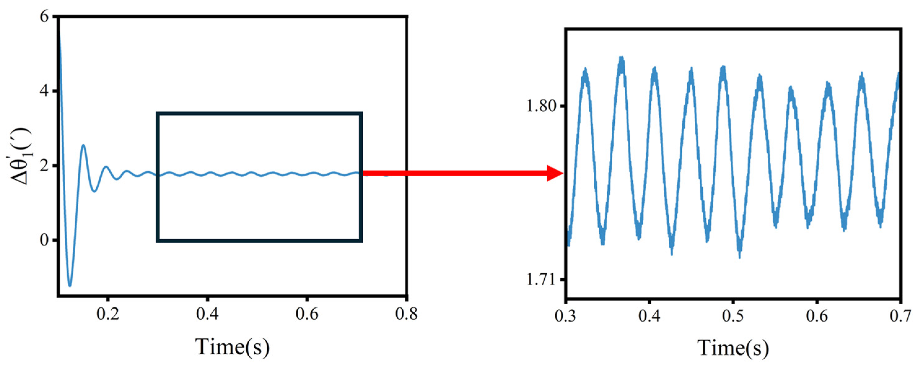
The following fact reflects the impact of the output shaft’s load on the TE at the same volume of wear: the average value of the DTE is smaller than the STE, probably because the gap is compensated by the load. And the instability of the load leads to greater fluctuations in the DTE. The following fact also reflects the impact of the cycloid gear’s flexibility on the TE: considering the flexible deformation, both the average value and the fluctuation of the TE are larger.
(2)
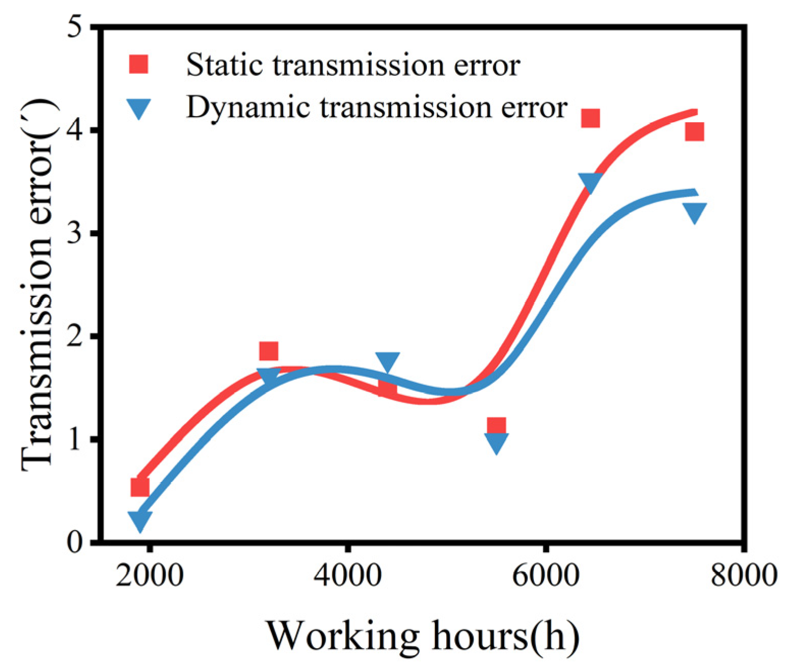
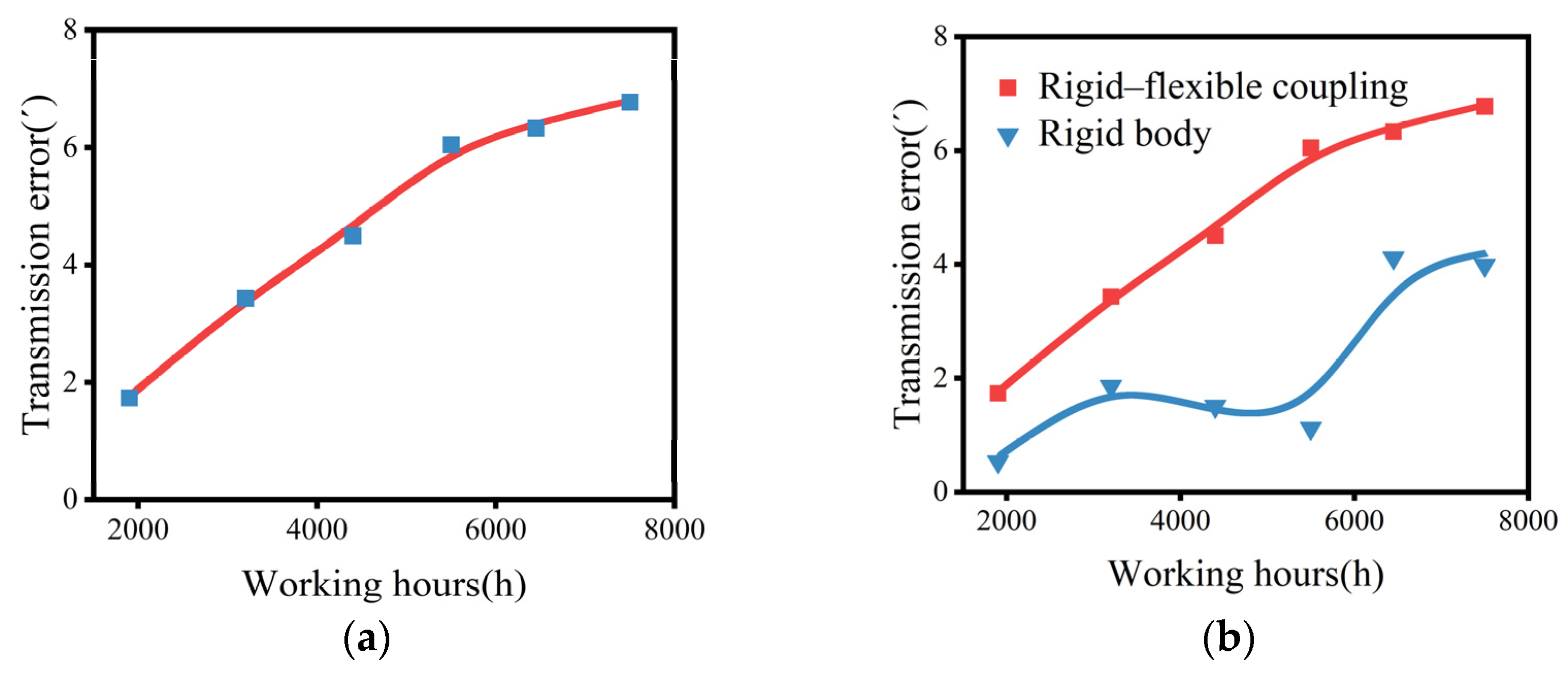
The following fact reflects the impact of different wear volumes on the TE: for both the STE and DTE of the full rigid body model, the wear volume increases with the growth of working time. Initially, the TE increases, occasionally decreases, and eventually tends to increase. For the rigid–flexible-coupled model, the TE monotonically increases with the existing wear volumes, but the rate tends to slow down.
(3)
While rigid-body analysis can save computational efficiency, there are certain differences in the degradation trend and degradation quantity compared to the rigid–flexible coupling model. Considering the actual wear test trend of the RV reducer [40], it is recommended to use the rigid–flexible coupling model for analysis.
(4)
In actual engineering, these measures can be taken to reduce the impact of wear on transmission accuracy, such as optimizing the tooth design, regular inspection and the replenishment of lubricants, keeping clean, and so on. In the later period, it is important to monitor the transmission accuracy to ensure that the performance of the RV reducer meets the requirements for usage.

Author Contributions

Conceptualization, M.W. and J.P.; methodology, M.W.; software, H.L.; validation, H.L. and J.P.; formal analysis, H.L., M.W., N.Z., Y.T. and J.P.; investigation, H.L.; writing—original draft preparation, H.L.; writing—review and editing, M.W., N.Z. and J.P.; visualization, H.L.; supervision, Y.T. and J.P.; project administration, Y.T.; funding acquisition, Y.T. All authors have read and agreed to the published version of the manuscript.

Funding

This research was funded by the National Natural Science Foundation of China [grant number 52075146], the National Natural Science Foundation of China Regional Joint Fund Integrative Project [grant number U23A6017], the National Key Research and Development Program [grant number 2022YFB4702100], and Science and Technology Cooperation Special Project of Shijiazhuang [grant number SJZZXA23001].

Data Availability Statement

Data are contained within the article.

Conflicts of Interest

The authors declare no conflicts of interest. The funders had no role in the design of the study; in the collection, analyses, or interpretation of data; in the writing of the manuscript; or in the decision to publish the results.

References

  1. Fang, L.T. Generation and investigation of a new cycloid drive with double contact. Mech. Mach. Theory 2012, 49, 270–283. [Google Scholar]
  2. Jang, D.J.; Kim, Y.C.; Hong, E.P.; Kim, G.S. Geometry design and dynamic analysis of a modified cycloid reducer with epitrochoid tooth profile. Mech. Mach. Theory 2021, 164, 104399. [Google Scholar] [CrossRef]
  3. Li, W.; Hao, L.J. Study on the degradation law of harmonic gear drive backlash with wear and assembly errors. Eng. Fail. Anal. 2022, 140, 106614. [Google Scholar] [CrossRef]
  4. Lin, K.; Chan, K.; Lee, J. Kinematic error analysis and tolerance allocation of cycloidal gear reducers. Mech. Mach. Theory 2018, 124, 73–91. [Google Scholar] [CrossRef]
  5. Sensinger, J.W. Unified Approach to Cycloid Drive Profile, Stress, and Efficiency Optimization. J. Mech. Des. 2010, 132, 024503. [Google Scholar] [CrossRef]
  6. Xu, L.X.; Chen, B.K.; Li, C.Y. Dynamic modelling and contact analysis of bearing-cycloid-pinwheel transmission mechanisms used in joint rotate vector reducers. Mech. Mach. Theory 2019, 137, 432–458. [Google Scholar] [CrossRef]
  7. Pham, A.-D.; Ahn, H.-J. High Precision Reducers for Industrial Robots Driving 4th Industrial Revolution: State of Arts, Analysis, Design, Performance Evaluation and Perspective. Int. J. Precis. Eng. Manuf.-Green Technol. 2018, 5, 519–533. [Google Scholar] [CrossRef]
  8. Duan, T.; Wei, J.; Zhang, A.; Xu, Z.; Lim, T.C. Transmission error investigation of gearbox using rigid-flexible coupling dynamic model: Theoretical analysis and experiments. Mech. Mach. Theory 2021, 157, 104213. [Google Scholar] [CrossRef]
  9. Xu, L.X.; Zhong, J.L.; Li, Y.; Chang, L. Design and dynamic transmission error analysis of a new type of cycloidal-pin reducer with a rotatable output-pin mechanism. Mech. Mach. Theory 2023, 181, 105218. [Google Scholar] [CrossRef]
  10. He, W.D.; Shan, L.J. Research and Analysis on Transmission Error of RV Reducer Used in Robot. Recent Adv. Mech. Des. Robot. 2015, 33, 231–238. [Google Scholar]
  11. Xu, H.; Shi, Z.; Yu, B.; Wang, H. Optimal Measurement Speed and Its Determination Method in the Transmission Precision Evaluation of Precision Reducers. Appl. Sci. 2019, 9, 2146. [Google Scholar] [CrossRef]
  12. Li, T.; Tian, M.; Xu, H.; Deng, X.; An, X.; Su, J. Meshing contact analysis of cycloidal-pin gear in RV reducer considering the influence of manufacturing error. J. Braz. Soc. Mech. Sci. Eng. 2020, 42, 133. [Google Scholar] [CrossRef]
  13. Zhang, M.; Zhang, Z.; Xiong, J.; Chen, X. Accuracy Analysis of Complex Transmission System with Distributed Tooth Profile Errors. Machines 2024, 12, 459. [Google Scholar] [CrossRef]
  14. Han, L.; Guo, F. Global sensitivity analysis of transmission accuracy for RV-type cycloid-pin drive. J. Mech. Sci. Technol. 2016, 30, 1225–1231. [Google Scholar] [CrossRef]
  15. Jin, S.; Tong, X.; Wang, Y. Influencing Factors on Rotate Vector Reducer Dynamic Transmission Error. Int. J. Autom. Technol. 2019, 13, 545–556. [Google Scholar] [CrossRef]
  16. Zhang, Y.; Chen, Z.; He, W. Virtual prototype simulation and transmission error analysis for RV reducer. Appl. Mech. Mater. 2015, 789, 226–230. [Google Scholar] [CrossRef]
  17. Li, X.; Huang, J.; Ding, C.; Guo, R.; Niu, W. Dynamic modeling and analysis of an RV reducer considering tooth profile modifications and errors. Machines 2023, 11, 626. [Google Scholar] [CrossRef]
  18. Ren, Z.-Y.; Mao, S.-M.; Guo, W.-C.; Guo, Z. Tooth modification and dynamic performance of the cycloidal drive. Mech. Syst. Signal Process. 2017, 85, 857–866. [Google Scholar] [CrossRef]
  19. Jia, C.; Fang, Z.D.; Zhang, Y.Z. Topography of modified surfaces based on compensated conjugation for the minimization of transmission errors of cylindrical gears. Mech. Mach. Theory 2017, 116, 145–161. [Google Scholar] [CrossRef]
  20. Bruyere, J.; Velex, P.; Guilbert, B.; Houser, D. An analytical study on the combination of profile relief and lead crown minimizing transmission error in narrow-faced helical gears. Mech. Mach. Theory 2019, 136, 224–243. [Google Scholar] [CrossRef]
  21. Archard, J.F. Contact and Rubbing of Flat Surfaces. J. Appl. Phys. 1953, 24, 981–988. [Google Scholar] [CrossRef]
  22. Bajpai, P.; Kahraman, A.; Anderson, N.E. A Surface Wear Prediction Methodology for Parallel-Axis Gear Pairs. J. Tribol. 2004, 126, 597–605. [Google Scholar] [CrossRef]
  23. Shen, X.; Liu, Y.; Cao, L.; Chen, X. Numerical Simulation of Sliding Wear for Self-lubricating Spherical Plain Bearings. J. Mater. Res. Technol. 2012, 1, 8–12. [Google Scholar] [CrossRef]
  24. Tunalioğlu, M.Ş.; Tuç, B. Theoretical and experimental investigation of wear in internal gears. Wear 2014, 309, 208–215. [Google Scholar] [CrossRef]
  25. Brandão, J.A.; Cerqueira, P.; Seabra, J.H.; Castro, M.J. Measurement of mean wear coefficient during gear tests under various operating conditions. Tribol. Int. 2016, 102, 61–69. [Google Scholar] [CrossRef]
  26. Mirparizi, M.; Fotuhi, A.R.; Shariyat, M. Nonlinear coupled thermoelastic analysis of thermal wave propagation in a functionally graded finite solid undergoing finite strain. J. Therm. Anal. Calorim. 2020, 139, 2309–2320. [Google Scholar] [CrossRef]
  27. Mirparizi, M.; Shariyat, M.; Fotuhi, A.R. A novel approach for generalized Green-Naghdi-type electro-magneto-thermo-hyperelasticity wave propagation and reflection investigations in near-incompressible layers under shock loads. J. Therm. Stress. 2024, 47, 743–765. [Google Scholar] [CrossRef]
  28. Zhang, R.H.; Zhou, J.X.; Wei, Z. Study on transmission error and torsional stiffness of RV reducer under wear. J. Mech. Sci. Technol. 2022, 36, 4067–4081. [Google Scholar] [CrossRef]
  29. Ishida, T.; Wang, H.; Hidaka, T.; Hashimoto, M. Rotational Transmission Error of K-H-V-Type Planetary Gears with Cycloid Gears: 2nd Report, Effects of Manufacturing and Assembly Errors on Rotational Transmission Error. Trans. Jpn. Soc. Mech. Eng. C 1994, 60, 3510–3517. [Google Scholar] [CrossRef]
  30. Wang, H.; Shi, Z.-Y.; Yu, B.; Xu, H. Transmission Performance Analysis of RV Reducers Influenced by Profile Modification and Load. Appl. Sci. 2019, 9, 4099. [Google Scholar] [CrossRef]
  31. Lu, L.S.; Zhang, F.X.; Tang, H.; Wan, Z.; Tang, Y. Equidistant & Radial-moving Modifications of Cycloidal Gear Tooth Profiles Used in RV Reducer Based on Optimized Carrying Capacity. China Mech. Eng. 2019, 30, 2022–2029. [Google Scholar]
  32. Su, J.X.; Li, C. Numerical Calculation and Analysis of Cycloidal Gear Wear Amount of RV Reducer. J. Mech. Transm. 2021, 45, 41–45+57. [Google Scholar]
  33. Zhang, J. Quasi-static-model-based wear analysis of spur gears. J. Mech. Eng. 2017, 53, 136–145. [Google Scholar] [CrossRef]
  34. Flodin, A.; Andersson, S. Simulation of mild wear in spur gears. Wear 1997, 207, 16–23. [Google Scholar] [CrossRef]
  35. Shen, Z.; Qiao, B.; Yang, L.; Luo, W.; Chen, X. Evaluating the influence of tooth surface wear on TVMS of planetary gear set. Mech. Mach. Theory 2019, 136, 206–223. [Google Scholar] [CrossRef]
  36. Ding, H.; Kahraman, A. Interactions between nonlinear spur gear dynamics and surface wear. J. Sound Vib. 2007, 307, 662–679. [Google Scholar] [CrossRef]
  37. Liang, S.F.; Deng, X.Z.; Li, T.X.; Wang, C.; Yang, J. Tooth contact analysis of cycloidal pinwheel drive in RV reducer of robot. J. Mech. Transm. 2017, 41, 17–22. [Google Scholar]
  38. Ambaye, G.A.; Lemu, H.G. Dynamic analysis of spur gear with backlash using ADAMS. Mater. Today Proc. 2021, 38, 2959–2967. [Google Scholar] [CrossRef]
  39. Cheng, M.; Qiu, C.; Li, J.F.; Zhang, J.; Zhang, W.; Feng, N.; Shi, X. Development and research of fatigue life testing device for robot reducer. J. Mech. Transm. 2019, 43, 156–160. [Google Scholar]
  40. Li, J.F.; Yang, Y.K.; Wang, X.F.; Yao, L.; Xiao, J. Reliability evaluation of RV reducers based on multi degenerate data. J. Mech. Transm. 2023, 47, 82–87. [Google Scholar]
Figure 1. The model of the RV reducer. 1—Planetary gear; 2—output shaft; 3—pin wheel housing; 4—crankshaft; 5—pinwheel; 6—cycloid gear; 7—rigid disk; and 8—input shaft.
Machines 12 00511 g001
Figure 2. Tooth profile of cycloid pinwheel transmission [28].
Machines 12 00511 g002
Figure 3. Flowchart for solving the maximum contact force.
Machines 12 00511 g003
Figure 4. The tooth profile of the cycloid gear with wear and without wear.
Machines 12 00511 g004
Figure 5. Construction of the RV reducer.
Machines 12 00511 g005
Figure 6. Finite element modeling of the cycloid gear.
Machines 12 00511 g006
Figure 7. The radius of curvature at different meshing angles.
Machines 12 00511 g007
Figure 8. Meshing force at different meshing angles.
Machines 12 00511 g008
Figure 9. Relative slip distance at different meshing angles.
Machines 12 00511 g009
Figure 10. Wear volume along the tooth profile under different working hours.
Machines 12 00511 g010
Figure 11. The full rigid body model without load: rotation speed of input gear (hidden line) and output shaft (solid line).
Machines 12 00511 g011
Figure 12. The static transmission error (STE) of the full rigid body model.
Machines 12 00511 g012
Figure 13. Sinusoidal load with an amplitude of 412 Nm.
Machines 12 00511 g013
Figure 14. The full rigid body model with sinusoidal load: rotation speed of the input gear (hidden line) and output shaft (solid line).
Machines 12 00511 g014
Figure 15. The dynamic transmission error (DTE) of the full rigid body model.
Machines 12 00511 g015
Figure 16. The rigid–flexible coupling model without load: rotation speed of input gear (hidden line) and output shaft (solid line).
Machines 12 00511 g016
Figure 17. The STE of the rigid–flexible coupling model.
Machines 12 00511 g017
Figure 18. The STE and the DTE of the full rigid body model.
Machines 12 00511 g018
Figure 19. The STEs are as follows: (a) a full rigid body model; (b) a comparison between the full rigid body model and rigid–flexible coupling model.
Machines 12 00511 g019
Table 1. The parameters of RV reducer.
ParametersValue
Number of cycloid gear teeth39
Pin number40
Eccentricity (mm)1.3
Pin radius (mm)3
Radius of center circle (mm)64
Degree of overlap1.3
Transmission ratio81
Radius of planetary gear indexing circle (mm)27
Pressure angle (°)30
Cycloid gear tooth width (mm)8.75
Rated output torque (Nm)412
Input speed (r/min)1500
Table 2. Material properties of the parts of the RV reducer.
ComponentsMaterialModulus of Elasticity/MPaPoisson’s RatioDensity/106
(kg/mm3)
Cycloid gearGCr15219,0000.37.83
Output shaftCrMnTi20212,0000.2897.86
CrankshaftGCr15219,0000.37.83
Pinwheel housingQT450169,0000.2577.06
PinwheelGCr15219,0000.37.83
Table 3. Virtual prototype constraint relation.
NumberComponentsConstraints
1Pin wheel housingGroundFixed
2Rigid diskOutput shaftFixed
3Planetary gear1Crankshaft1Fixed
4Planetary gear2Crankshaft2Fixed
5Input shaftGroundRevolution
6Input shaftRigid diskRevolution
7Planetary gear1Rigid diskRevolution
8Planetary gear2Rigid diskRevolution
9Crankshaft1Cycloid gear1Revolution
10Crankshaft1Cycloid gear2Revolution
11Crankshaft2Cycloid gear1Revolution
12Crankshaft2Cycloid gear2Revolution
13PinwheelPin wheel housingRevolution
Disclaimer/Publisher’s Note: The statements, opinions and data contained in all publications are solely those of the individual author(s) and contributor(s) and not of MDPI and/or the editor(s). MDPI and/or the editor(s) disclaim responsibility for any injury to people or property resulting from any ideas, methods, instructions or products referred to in the content.

