Article

Experimental Study on Vibration and Noise Reduction of Gear Transmission System Based on ISFD

Engineering Center of Ministry of Education of Chemical Safety, Beijing University of Chemical Technology, Beijing 100029, China
*
Author to whom correspondence should be addressed.
Machines 2024, 12(8), 531; https://doi.org/10.3390/machines12080531
Submission received: 13 June 2024 / Revised: 24 July 2024 / Accepted: 1 August 2024 / Published: 5 August 2024
(This article belongs to the Section Machine Design and Theory)

Abstract

:
Gear transmission systems are widely used in ship propulsion systems, but, during operations, they produce serious vibration and noise problems, reducing the fatigue life of gears and affecting the performance of ships and the comfort of operators. Taking into account the complex frequencies and vibration components of gear transmission systems, this study conducted wide-band vibration suppression and noise reduction research on a gear transmission system using an integral squeeze film damper (ISFD), providing a novel approach for reducing vibration and noise in gear transmission systems. By conducting a simulation analysis and numerical calculations, the ISFD was analyzed via a static analysis and a dynamic analysis. We developed an experimental platform for reducing vibration and noise in gear transmission systems using sliding bearings, and the experiments were conducted under different speed and load conditions to study the vibration suppression and noise reduction of gears based on the ISFD. The experimental results show that the ISFD has good vibration suppression capabilities for gears at different speeds, with a horizontal vibration reduction of 75.44% and a vertical vibration reduction of 68.48% at 2400 r/min. The ISFD has wide-band vibration suppression capabilities, especially for mesh frequency and twice-mesh frequency, with a vibration reduction of 86.96% or more. Moreover, the ISFD has good vibration suppression capabilities for gears at different load torques, with a reduction of more than 35% in all directions. In addition, the ISFD also has noise reduction capabilities, reducing the gears’ noise by 1.92 dB at different speeds.

1. Introduction

Gear transmission systems are widely used in marine transmission systems; in both surface ships and underwater submarines, gear transmission systems have been proven to exhibit high reliability and good transmission performance. The development of modern marine propulsion systems requires higher reliability, higher vibration levels, and lower noise levels in gear transmission systems. Therefore, it is highly important to study vibration and noise suppression methods for gear transmission systems to improve the performance of marine propulsion systems [1]. Although there are currently many passive vibration damping methods for gear transmission systems, these methods usually only have good damping effects on gear vibrations at specific frequencies, and they cannot achieve broadband damping [2].
The squeeze film damper (SFD) was initially used in aviation engines due to its excellent damping performance; it was then widely used in various kinds of rotating machinery, such as steam turbines and motors [3]. In recent years, the SFD has gradually been used to reduce the vibration of gear transmission systems [4]. Jian et al. [5] studied the nonlinear dynamic behavior of a squeeze film gear–damper system, considering the strong nonlinear oil film force, the nonlinear frictional-collision force between the rotor and the stator, and the meshing force of the gears. Chen et al. [6,7] studied the vibration control effect of the SFD on a high-speed helical gear transmission system via theoretical and experimental studies; they found that the SFD can suppress the vibration of the helical gear transmission system at high speeds. Chang et al. [8,9] studied the pressure distribution and dynamics of gears after using the SFD, finding that, under the influence of the lubricating oil film force after using the SFD, the gears present complex dynamics and need to be transformed from a chaotic motion to a steady periodic motion through the application of control strategies. Traditional squeeze film dampers exhibit severe nonlinear vibration issues in non-design conditions and adverse operating conditions [10]. Due to the harsh working conditions of gears (especially ship gears) and the need to work in multiple operating conditions, the traditional SFD cannot effectively suppress vibrations in gear transmission systems, and may even exacerbate vibrations in gear transmission systems. The commonly used squeeze film dampers are the cage-type squeeze film damper and the elastic ring-type squeeze film damper. The cage-type squeeze film damper requires a larger axial installation space and provides less damping; the elastic ring-type squeeze film damper has a very low stiffness and cannot withstand large loads. Traditional squeeze film dampers have only been applied and studied in ship steam turbines and gas turbines, and have not been applied in gear transmission systems.
The integral squeeze film damper (ISFD) is a new type of SFD. The design of the ISFD uses a squeeze film area as a segmented structure to avoid the circumferential flow of oil film in the gap, thus solving the highly nonlinear problem of the SFD. Meanwhile, the ISFD has the feature of being compact and easy to disassemble. Therefore, the ISFD not only shows superior vibration control performance, but also improves the rotor stability [11,12,13,14]. Ferfecki et al. [15] established a CFD model for a segmented ISFD and solved it; the calculation results show that the ISFD has better dynamic characteristics compared to a traditional SFD. Andres et al. [16] explored the influence of different end seals on the stiffness and damping of the ISFD; their experimental results show that the damping provided by the ISFD increases with the increase in the rotor eccentricity, and the ISFD with an end-cover seal provides damping that is up to nearly 20 times more effective than the ISFD without the end cover. Yan et al. [17,18] conducted experiments on the response of a single-disc rotor system to different fundamental excitation conditions with the ISFD. Zhang [19] used the non-dominated sorting genetic algorithm (NSGA-II) and gray correlation analysis (GRA) algorithm to optimize the stiffness and stress of the ISFD using multi-objective optimization. The ISFD has been used in steam turbines, centrifuges, gas turbines, etc. [20,21,22], and has achieved significant damping effects. However, there is currently a lack of research on the impact of ISFDs on the vibration of gear transmission systems.
This study applies the ISFD to a gear system for the purposes of vibration reduction; it establishes the ISFD model, and we conduct a static analysis and a dynamic analysis of the ISFD. Moreover, we establish an experimental platform for reducing vibration and noise levels in gear transmission systems using sliding bearings, and the experimental results show that ISFD can effectively suppress the vibrations transmitted from the gear meshing to the gearbox body; it can also effectively suppress the vibration of the gears within a wide frequency range. In addition, we conduct an experiment focused on reducing the noise of the gear transmission system with the ISFD, verifying the noise reduction capabilities of ISFD.

2. Materials and Methods

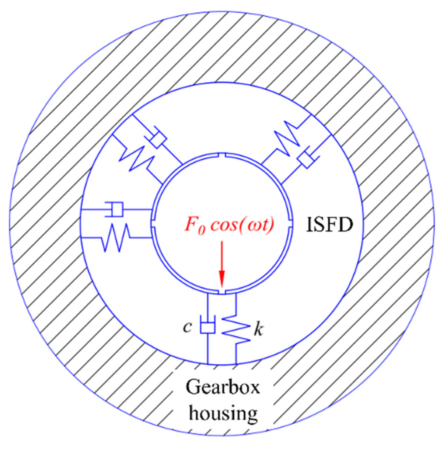
2.1. Vibration Isolation Modeling of the ISFD

The ISFD support is shown in Figure 1; it consists of bolts, end caps, gaskets, and the ISFD. The ISFD consists of the outer ring, the squeezing film area, the S-shaped elastomers, and the inner ring. The elastomers provide a lower stiffness for the damper. The inner ring of the ISFD is over-centered with the bearing, and the outer ring is also over-centered with the gearbox housing. The vibration isolation model of the ISFD is shown in Figure 2.
The vibration of the gear can be transmitted to the inner ring of the ISFD through the bearing. In Figure 2, k and c represent the stiffness and damping of the ISFD. Vibration ultimately manifests as a vibrating force F0cos(ωt), where ω represents the excitation frequency. The inner ring vibrates and the fluid is squeezed within the gaps in the film squeezing area, generating a viscous damping force to dissipate some of the vibration energy. The special structure of the ISFD gives it good vibration control abilities. The dynamic equation of the vibration isolation structure of ISFD is:
M x ¨ + C   x ˙ + K x = F 0 cos ( ω t )
where M, C, and K represent the mass, damping, and stiffness of the ISFD, respectively; x represents the vibrational displacement of the ISFD. The vibration response transmitted to the gearbox can be represented as:
x 0 = F 0 K 1 1 z 2 + 2 j ζ z
where z = ω/ω0 represents the frequency ratio of the ISFD, and ζ = C / 2 K M is the damping ratio of the system. The force transmitted through the ISFD to the bearing housing can be expressed as:
P = j ω C x 0 + K x 0
The force transmission coefficient from the ISFD to the gearbox is:
T f = P F 0 = 1 K j ω C + K ( 1 - z 2 + 2 j ζ z ) = 1 + ( 2 j ζ z ) 2 ( 1 - z 2 ) 2 + ( 2 ζ z ) 2
The elastomers of ISFD have very low levels of structural damping, which can be neglected, so Equation (4) becomes:
T f = P F 0 = 1 1 - z 2
Equation (5) shows that, when the frequency ratio z 2 , the force transmission coefficient is less than 1, and the system has an isolation effect. That is, when ω 2 ω0, the ISFD can play an isolating role. The primary excitation frequency of the gears is the meshing frequency, fm = 1120 Hz, and the double meshing frequency 2 fm = 2240 Hz. The natural frequency of ISFD was calculated to be 254 Hz. Consequently, the calculated transfer coefficient Tf equals 0.086 and 0.016, significantly less than 1, indicating that the ISFD effectively isolates vibration from the gear transmission system, reduces transmitted vibration energy to the surroundings, and enhances system stability.

2.2. Statics Analysis of ISFD

The inner diameter and outer diameter of the ISFD match both the outer diameter of the bearing and the inner diameter of the gearbox. The load-bearing capacity of the ISFD is influenced by its inner diameter, outer diameter, and axial width. Consequently, to prevent the ISFD from being subjected to excessive excitation forces that might cause failure, the stress distribution in the design must be verified. Therefore, a 3D model of the ISFD was established for the static analysis to ensure that the designed ISFD structure is reasonable and can operate safely and stably. The 3D analysis model of the ISFD is shown in Figure 3, and the structural parameters of the ISFD are shown in Table 1.
The material used for the ISFD is 4Cr13 stainless steel, which has good mechanical processing performance, high toughness, good overall performance, and strong corrosion resistance, thereby ensuring the safe and stable operation of the ISFD in the ship operating environment. The elastic modulus of 4Cr13 stainless steel is 215 GPa, the density is 7.75 g/cm3, and the yield limit is 540 MPa. The formula for calculating the allowable stress is:
σ = σ s n s
where σs represents the yield limit, the safety limit ns is taken to be 1.5, and the allowable stress [σ] = 360 MPa. The tangential force Fn generated by the gears can be calculated using the following formula:
F n = 2 T d / cos α
where T is the load torque, which is taken as 50 N·m. d is the diameter of the driven gear, which is 283.5 mm, and α is the pressure angle of the gear pair, which is 20°. The calculated value of Fn is 375.37 N. Taking into account the dynamic load caused by the weight of the gears, the weight of the gears is m = 33.52 kg, and the dynamic load coefficient nd = 2.5 is taken. The resultant force on ISFD is:
F 0 = m g × n d + F n = 1196.61 N
The result of the calculation is rounded up to obtain the ISFD subjected to the maximum force F0 = 1200 N. Since the outer ring of the ISFD is fixed to the bearing housing and the inner ring is connected to the bearing, the excitation force is transmitted from the bearing to the inner ring of the ISFD. Therefore, a fixed constraint is applied to the outer ring and a load of 1200 N is applied to the inner ring. Figure 4 shows the static analysis results for the ISFD.
The stress cloud map presented in Figure 4a reveals that the maximum stress experienced by the ISFD is 196.02 MPa, which falls below the allowable stress [σ] = 360 MPa. Notably, this peak stress occurs within the S-shaped elastomer, while exhibiting a uniform distribution throughout without any discernible concentration of stresses. This shows that the designed ISFD structure is reasonable, ensuring its safety and stability during operational usage.
The displacement analysis given in Figure 4b reveals that the maximum displacement is approximately 0.25 mm, which is less than the oil film gap of 0.5 mm. Consequently, during gear operations, there will be no contact between the ISFD and the bottom surface, ensuring its uninterrupted damping and vibration reduction capabilities. Moreover, the substantial overall displacement observed in the inner ring of the ISFD indicates that, upon transmission of vibrational excitation to the ISFD, significant motion is induced in its inner ring, resulting in the complete compression of the oil film region and generating a higher damping force for the ISFD. This unique finding, shown in Figure 4b, can be utilized to calculate the stiffness coefficient of the ISFD as k = 3.99 × 10⁶ N/m.
The above analysis ensures the safe and stable operations of the ISFD under rated loads, enabling it to effectively dampen vibrations and guaranteeing the reliability of the gear transmission system.

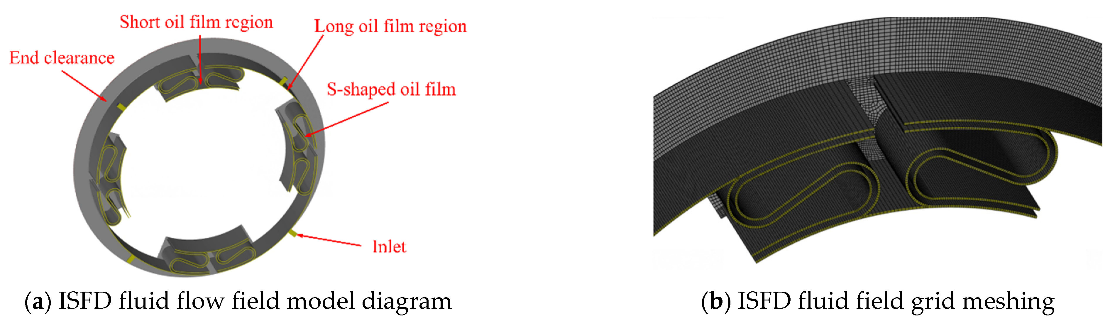
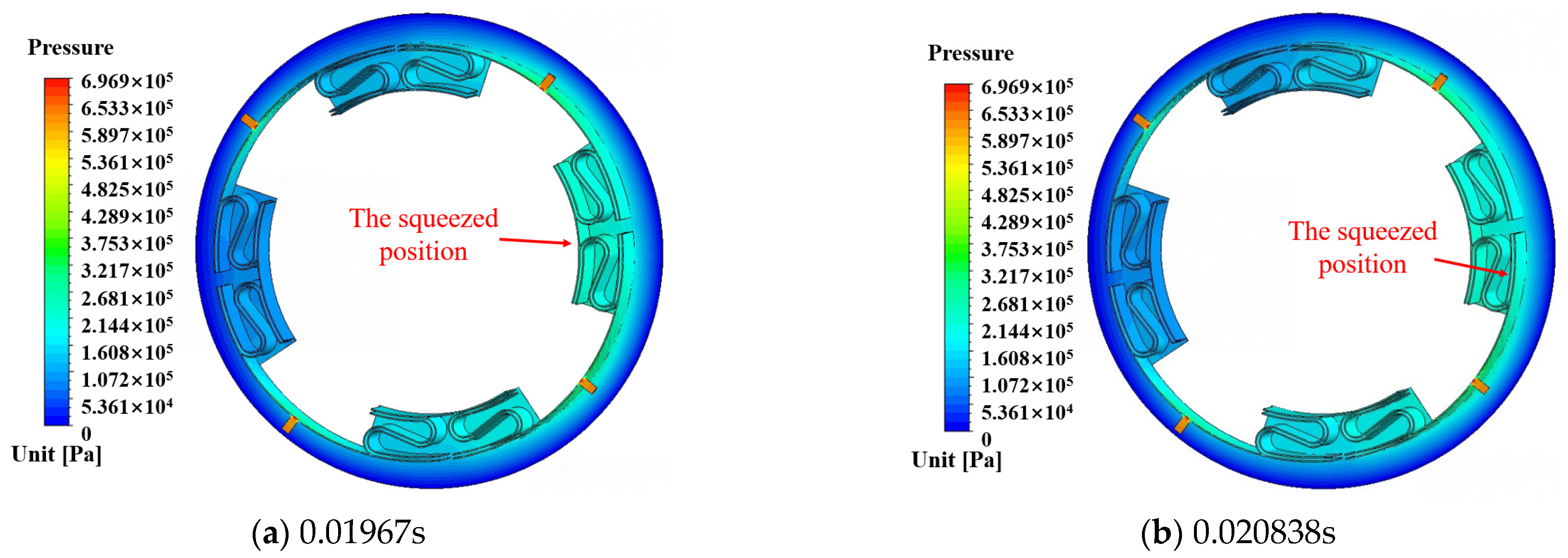
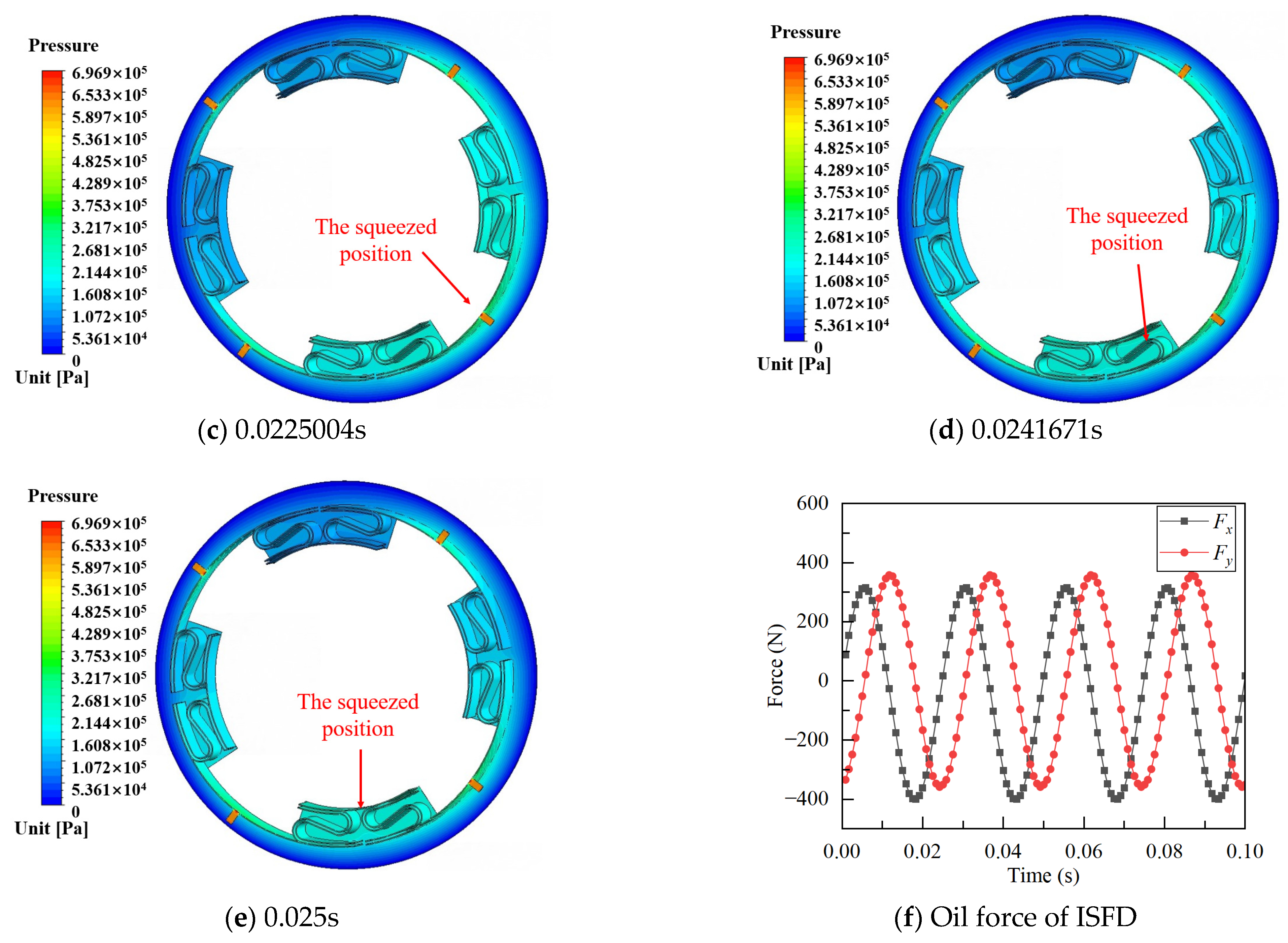
2.3. CFD Analysis of the ISFD

Since the ISFD is a symmetrical structure, based on the structural parameters of the ISFD, a 1/2 flow field model was established for ease of calculation. The flow field model is shown in Figure 5, and it comprises the following components: 4 long oil film regions, 4 short oil film regions, 4 inlet holes, 4 pairs of S-shaped oil films, and the end clearance. The lubricating oil enters the short oil film and long oil film of the ISFD from the 8 inlets. The inner ring of the ISFD receives vibration excitation and compresses the oil film region. Therefore, the inner walls of the flow field are set as dynamic grids that connect to the inner ring, and the rest are set as static grids. The lubricating oil is squeezed out from the end clearance, producing a large amount of damping. The dynamic simulation parameters of the ISFD are shown in Table 2.
Before conducting the CFD analysis, the Reynolds number must be calculated to determine the fluid’s flow state. The Reynolds equation for the squeezed oil film fluid is:
R e = ρ Ω h 2 μ
where Re represents the Reynolds number, ρ is the lubricating oil density, Ω is the whirling velocity, h is the oil film gap, and μ is the lubricating oil viscosity. By substituting the numerical values of the parameters in Table 2 into Equation (7), the Reynolds number Re in the ISFD flow field is calculated to be 1.44, which is much smaller than 2000. Therefore, the lubricating oil flow in the ISFD flow field is laminar. During the CFD analysis process, residual monitoring is turned on, and the convergence residual is set to 1 × 10⁻⁶. We use transient analysis to solve the problem, and the iteration time interval is set to 1/100 of the whirling cycle.
The equation for the whirling motion within the oil film on the inner wall of the ISFD is as follows:
d x = D cos Ω t d y = D sin Ω t
where dx and dy represent the displacements of the inner ring of the ISFD in the x and y directions, respectively, and D is the amplitude of the whirling motion. The velocities vx and vy of the inner ring of the ISFD in the x and y directions can be obtained by taking the derivative of Equation (8) with respect to time.
v x = D Ω sin Ω t v y =     D Ω cos Ω t
The flow field parameters of ISFD are set according to Table 2. The whirling frequency of the ISFD is 40 Hz, and the whirling cycle of the inner wall of the ISFD is 0.025 s. Considering the symmetrical nature of the ISFD’s structure, an analysis is conducted of the motion state during a quarter-cycle to elucidate the movement characteristics within the flow field during operation. Figure 6 presents the pressure distribution maps illustrating a quarter of the whirling cycle.
Figure 6a–e show that the squeezed position of the ISFD changes continuously over a quarter of the whirling cycle. The squeezed position moves from the short oil film region to the S-shaped oil film, then to the long oil film region, and then to the next short oil film region, and a quarter of the whirling cycle is completed. The pressure distribution of the ISFD’s flow field was calculated to obtain the oil film force distribution in the x direction and the y direction, as shown in Figure 6f. As indicated in Figure 6f, Fx is the x-direction oil film force, and Fy is the y-direction oil film force; the oil film force generated by the ISFD is sinusoidally distributed, and there is no obvious discontinuity in the oil film force generated by the ISFD. The ISFD can generate a stable damping force to absorb the vibration energy of the gear system and effectively prevent the occurrence of nonlinear problems.
The damping coefficients cxx and cyy in the x direction and y direction of the ISFD can be obtained by integrating the oil film force Fx in the x direction and the oil film force Fy in the y direction. The accuracy of both stiffness and damping calculation methods has been verified through experiments [23].
c x x = F x v x = F x v x c y y = F y v y = F y v y
The damping coefficient of the ISFD obtained via calculations is shown in Table 3.
To investigate the damping characteristics of the ISFD under different lubrication oil conditions, the damping characteristics of the ISFD were calculated at lubrication oil supply pressures of 0.3 MPa, 0.4 MPa, 0.5 MPa, 0.6 MPa, and 0.7 MPa. Since the oil film force and damping coefficient in the x and y directions of the ISFD are similar, only the damping force and damping coefficient in the x direction were compared. The oil film force and damping coefficient of the ISFD under different pressure conditions are shown in Figure 7.
As shown in Figure 7, with the increase in the lubrication oil pressures, the oil film force and damping coefficient of ISFD exhibit a marked upward trend: the oil film force increases by 45.46% and the damping coefficient increases by 46.9% as the lubrication oil pressures rises from 0.3 MPa to 0.7 MPa. Therefore, increasing the lubrication oil pressures of the ISFD within a certain range can effectively enhance its damping coefficient and improve its damping vibration ability.
In the design process of the ISFD, it is essential to consider the stiffness and damping of the bearing, ensuring that the stiffness of the ISFD is marginally lower than that of the bearing. An excessive stiffness coefficient in the ISFD may disperse gear transmission vibration and hinder the formation of a squeezing oil film effect. Conversely, insufficient stiffness in the ISFD could exacerbate vibration. Therefore, maintaining slightly lower stiffness than that of the bearing for the ISFD is crucial. Additionally, a significantly higher damping coefficient in the ISFD compared to that of the bearing can enhance its damping and vibration reduction effectiveness. The respective values for stiffness and damping coefficients in the bearing are 4.24 × 10⁶ N/m and 37.1 N·s/m, validating the rationality of the ISFD design.

3. Experimental Setup

To study the vibration reduction performance of the ISFD on the gear transmission system, we set up an experimental platform for assessing the vibration reduction of the gear transmission system using a sliding bearing. The detailed parameters of the gears used in the experiment are listed in Table 4. The installation space for the ISFD was reserved in advance in the support position of the gearbox. End caps and oil seals were installed on both sides of the support structure to form a closed oil chamber between the end caps and the gearbox body, ensuring that the ISFD and the sliding bearing could be fully lubricated. Figure 8 shows a schematic diagram of the experimental platform, including a schematic diagram of the gearbox and a schematic diagram of the ISFD.
The bearings use elliptical wedge sliding bearings, and the gearbox rated speed is 2400 r/min. The lubrication pressure for the bearing and the ISFD is 0.3 MPa. The test system uses the m + p Vibpilot. Acceleration sensors are installed on the input and output of the gearbox to measure the horizontal (x-direction) and vertical (y-direction) vibrations of the gearbox. A magnetic powder brake is used as the load for the gearbox, and a torque sensor is used to connect the output shaft of the gearbox to the magnetic powder brake and measure the load torque applied to the gearbox by the magnetic powder brake. The experimental platform for vibration reduction in the gear transmission system is shown in Figure 9.

4. Results and Discussion

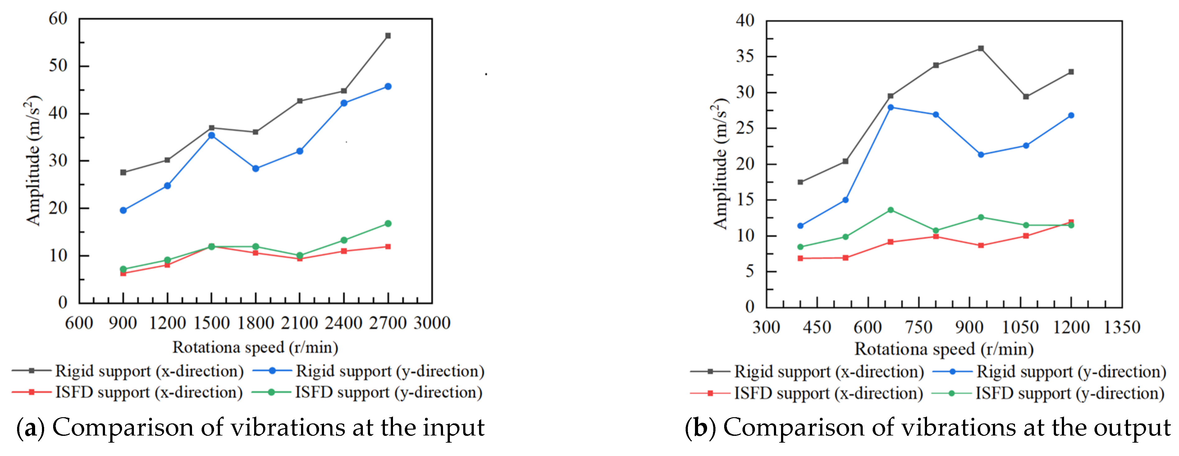
4.1. Experimental Analysis of Vibration Reduction in the Gear Transmission System Using the ISFD

To verify the vibration reduction capability of the ISFD for the gear transmission system, an experiment was conducted to suppress the vibration of the gearbox using the ISFD. During the experiment, the load torque of the gear system was set to 0 N·m, and the motor speed n1 was set to 900 r/min–2700 r/min, corresponding to the rotational speed of the driven shaft n2 = n1/I = 400 r/min–1200 r/min. The vibration data were recorded every 300 rpm when the motor speed increased. The comparison chart of the vibration acceleration of the gear transmission system under the two support structures was obtained, as shown in Figure 10.
Figure 10 shows that the vibration at the input of the gearbox is greater than that at the output within the experimental speed range, and the x-direction vibration is greater than the y-direction vibration. When the gearbox is supported by rigid supports, the vibration at both the input and output of the gearbox is at a relatively high level. There is an obvious trend of the gearbox body’s vibration increasing with speed. After replacing the ISFD supports, the vibration of the gearbox was significantly suppressed, and the trend of vibration increasing with speed became less pronounced. At 2400 r/min, the peak value of the x-direction vibration acceleration was reduced from 44.78 m/s2 to 11.00 m/s2, a reduction of 75.44%; the peak value of the y-direction vibration acceleration was reduced from 42.23 m/s2 to 13.31 m/s2, a reduction of 68.48%.
Because the rotational speed at the gear input end is higher, the vibration is more noticeable, and it has a greater impact on the overall vibration of the gearbox. Therefore, time-domain and frequency-domain analyses were performed on the x-direction vibration signals at the input of the gearbox. Time-domain and frequency-domain analyses were performed on the x-direction vibration signals at the input of gearbox. Figure 11 shows a comparison of time-domain and frequency-domain vibrations at the gearbox input in the x direction with rigid support and ISFD support.
The gearbox vibration exhibits noticeable impact vibrations, as shown in Figure 11a. The input speed of the gearbox is n1 = 2400, the rotating frequency (fn) of the input speed is calculated as n1/60, and the meshing frequency (fm) is determined to be z1n1/60 = z2n2/60 = 1120 Hz.
Figure 11b demonstrates that the gearbox exhibits relatively complex vibration components with prominent peaks at fn and its multiples (2fn, 3fn), the meshing frequency fm, and the double meshing frequency (2fm). Upon replacing the rigid support with the ISFD, significant vibration reduction can be observed across all frequencies, particularly for fm and 2fm, where a pronounced damping effect is evident. The ISFD displays remarkable capabilities in suppressing complex vibrations within transmission systems. The ISFD possesses wide-band vibration suppression abilities. The vibration reduction effects of the gearbox at fm and 2fm by the ISFD are summarized in Table 5, which shows that the reduction at fm and 2fm is more than 86.96% after using ISFD. The ISFD has good vibration suppression effects on the impact vibration caused by gear meshing, which can reduce the external force caused by the gear meshing impact.

4.2. The Effect of Different Torque Loads on the Vibration Control of the ISFD

The load torque has a significant impact on the vibration of the gear transmission system. In order to study the influence of torque loads on the ISFD, an experiment was conducted to investigate their effect on the vibration reduction performance of the ISFD. The input speed of the gearbox was set at 2400 r/min, and the load torque was set at 0 N·m–30 N·m, with data recorded every 5 N·m. By comparing the vibrations of the gearbox under different load torque conditions with ISFD support and rigid support, the influence of torque on the vibration reduction ability of the ISFD was explored. Figure 12 shows the comparison of the vibration of the gearbox under different load torque conditions with ISFD support and rigid support.
Figure 12 shows that, under rigid support conditions, as the torque increases, the vibrations in the x and y directions of the gearbox increase, and the y-direction vibration is more sensitive to changes in torque. After replacing the ISFD support, the vibration amplitudes in the x and y directions of the gearbox show good effects at all torque levels. The vibration reduction rate slightly decreases with the increase in the load torque. In the test range, the vibration reduction rate is more than 35% at all torque levels.

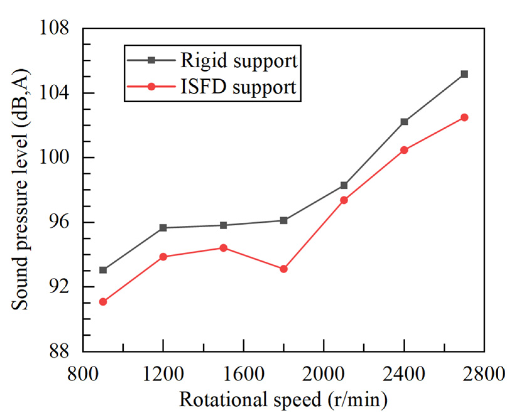
4.3. Experimental Study of the ISFD’s Reduction in Gear Transmission System Noise

We investigated the effect of the ISFD on the suppression of noise in the gear transmission system, while at the same time reducing vibrations. An experiment was conducted to suppress noise in the gear transmission system with the ISFD. A noise sensor was installed 200 mm away from the input end of the gearbox to collect the noise radiated from the gearbox to the outside. The noise reduction capabilities of the ISFD support at different speeds were investigated by comparing the noise obtained under rigid support and ISFD support. Figure 13 shows the noise of the gearbox under different support conditions.
Figure 13 shows that the noise of the gearbox increases with an increase in the input speed. The ISFD has a suppressing effect on the noise of the gearbox under different rotational speed conditions. When the input speed of the gearbox was 2400 rpm, the sound pressure of the rigid support noise reached 102.21 dB. After replacing the rigid support with the ISFD, the noise sound pressure was reduced to 100.47 dB, a decrease of 1.74 dB. The average noise reduction at different rotational speeds was 1.92 dB. The ISFD not only reduces the external vibration of the gearbox but also suppresses the noise it emits, improving the performance of the ship’s power system.

5. Conclusions

In order to achieve wide-band vibration suppression for the complex vibration characteristics of gear transmission systems in ship propulsion systems, this study used an ISFD to suppress the vibration and reduce the noise of a gear transmission system. Static and dynamic analyses of the ISFD were conducted. We set up an experimental test rig for the vibration reduction and noise suppression of the gear transmission system with sliding bearings. The experimental verification confirmed the vibration suppression and noise reduction performance of the ISFD for the sliding bearing–gear transmission system, and the following conclusions were drawn:
(1) An ISFD model was established, and a static analysis and a dynamic analysis were conducted. The results show that the structural design of the ISFD is reasonable, and the maximum stress is lower than the allowable stress. The stiffness of the ISFD was calculated to be k = 3.99 × 10⁶ N/m. The law of change in the flow field during ISFD operations was explored. The ISFD can provide a uniform damping force to dissipate the vibration energy. The damping coefficient of the ISFD was calculated to be cxx = 4.57 × 10⁴ N·m/s, cyy = 4.54 × 10⁴ N·m/s.
(2) Vibration reduction tests were conducted for the gear transmission systems at different speeds. After installing the ISFD, the vibrations of the gearbox were effectively suppressed: at 2400 r/min, the horizontal vibrations of the gearbox were reduced by 75.44%; the vertical vibrations were reduced by 68.48%. The ISFD also has wide-band vibration suppression abilities, especially the vibrations at fm and 2fm. After using the ISFD, the drop in vibration levels at fm and 2fm was greater than 86.96%.
(3) Vibration reduction tests were conducted for gear transmission systems under different load torques. The ISFD showed effective control over gearbox vibrations under different load conditions, with vibration reductions of more than 35% in all cases.
(4) Noise reduction tests were conducted for the gear transmission systems. The experimental results show that the ISFD also suppresses the noise emitted by the gear transmission system. The average noise reduction of a gear transmission system emitting noise at different speeds is 1.92 dB.

Author Contributions

Conceptualization, G.Z.; methodology, G.Z.; validation, G.Z., and Q.Q.; investigation, G.Z., and Z.T.; data curation, G.Z.; writing—original draft preparation, G.Z.; writing—review and editing, X.J.; visualization, G.Z.; supervision, L.H.; project administration, L.H. All authors have read and agreed to the published version of the manuscript.

Funding

This research received no external funding.

Data Availability Statement

The data that support the findings of this study are available on request from the corresponding author upon reasonable request.

Conflicts of Interest

The authors declare no conflict of interest.

References

  1. Geng, Z.; Li, J.; Xiao, K.; Wang, J. Analysis on the vibration reduction for a new rigid-flexible gear transmission system. J. Vib. Control 2022, 28, 2212–2225. [Google Scholar] [CrossRef]
  2. Xiao, W.Q.; Xu, Z.H.; Wang, S.; Yu, S.W.; Qin, K.; Hu, D.K. Research on vibration reduction characteristics of continuum and noncontinuum system on coupling for high-power gear transmission based on particle damping materials. Shock Vib. 2021, 2021, 8845526. [Google Scholar] [CrossRef]
  3. Wang, S.; Han, F.; Sun, B.; Li, H. Squeeze-film air damping of a five-axis electrostatic bearing for rotary micromotors. Sensors 2017, 17, 1119. [Google Scholar] [CrossRef]
  4. Chen, W.; Chen, S.; Hu, Z.; Tang, J.Y.; Li, H.N. A novel dynamic model for the spiral bevel gear drive with elastic ring squeeze film dampers. Nonlinear Dyn. 2019, 98, 1081–1105. [Google Scholar] [CrossRef]
  5. Jian, B.L.; Chu, L.M.; Chang, Y.P.; Chang, J.; Cai, W. Nonlinear dynamic analysis of gear-rotor-bearing system equipped with HSFD under hydraulic actuator active control. J. Low Freq. Noise Vib. Act. Control 2019, 40, 146134841988621. [Google Scholar] [CrossRef]
  6. Dong, H.; He, L.; Jia, X. Using integral squeeze film damper to suppress vibration of gas turbine. J. Vib. Eng. Technol. 2023, 11, 3163–3170. [Google Scholar] [CrossRef]
  7. Chen, W.; Chen, S.; Tang, J.; Li, H. Stability and bifurcation analysis of a bevel gear system supported by finite-length squeeze film dampers. Nonlinear Dyn. 2020, 100, 3321–3345. [Google Scholar] [CrossRef]
  8. Chang, J.; Cai, W.; Yau, H.T. Non-linear dynamic analysis of hybrid squeeze-film damper-mounted gear-bearing system and hydraulic active control. Proc. Inst. Mech. Eng. Part K J. Multi-Body Dyn. 2010, 224, 249–259. [Google Scholar]
  9. Chang, J.; Cai, W. Gear dynamics analysis with turbulent journal bearings mounted hybrid squeeze film damper—Chaos and active control analysis. ASME J. Comput. Nonlinear Dyn. 2015, 10, 011011. [Google Scholar] [CrossRef]
  10. Zapoměl, J.; Ferfecki, P.; Molčan, M. Optimization of control parameters of magnetorheological squeeze film dampers to minimize the vibration amplitude of rotors passing the critical speed. Appl. Sci. 2023, 13, 6905. [Google Scholar] [CrossRef]
  11. Andrés, L.S.; Jeung, S. Experimental performance of an open ends, centrally grooved, squeeze film damper operating with large amplitude orbital motions. ASME. J. Eng. Gas. Turbines Power 2015, 137, 032508. [Google Scholar] [CrossRef]
  12. Adiletta, G.; Pietra, L.D. The squeeze film damper over four decades of investigations. Part II: Rotordynamic analyses with rigid and flexible rotor. Shock Vib. Dig. 2002, 34, 97–126. [Google Scholar]
  13. Pietra, L.D.; Adiletta, G. The squeeze film damper over four decades of investigations. Part I: Characteristics and operating features. Shock Vib. Dig. 2002, 34, 3–26. [Google Scholar]
  14. Wang, W.; He, L.; Sun, Y.; Wang, Z.; Zhang, H.; Bao, Q. Research on new integral squeeze film damper vibration control of micro turbojet engine at high speed. J. Vib. Eng. Technol. 2023, 40, s451–s462. [Google Scholar] [CrossRef]
  15. Ferfecki, P.; Zapoměl, J.; Gebauer, M.; Polerich, V.; Křenek, J. A computational fluid dynamics investigation of the segmented integral squeeze film damper. MATEC Web Conf. 2019, 254, 8005. [Google Scholar] [CrossRef]
  16. Lu, X.L.; Andres, L.S.; Koo, B.; Tran, S. On the effect of the gap of end seals on force coefficients of a test integral squeeze film damper: Experiments and predictions. J. Eng. Gas. Turb. Power 2020, 143, 011014. [Google Scholar] [CrossRef]
  17. Yan, W.; He, L.; Zhu, G.; Wang, S.; Deng, Z. Experimental study on vibration suppression in a rotor system under base excitation using an integral squeeze film damper. High Technol. Lett. 2020, 26, 11. [Google Scholar]
  18. Yan, W.; He, L.; Zhu, G.; Jia, X. Effect of G-type integral squeeze film damper on the dynamic characteristics in rotor system. Int. J. Turbo Jet. Eng. 2023, 40, s195–s205. [Google Scholar] [CrossRef]
  19. Zhang, Y.; He, L.; Yang, J.; Zhu, G.; Jia, X.; Yan, W. Multi-objective optimization design of a novel integral squeeze film bearing damper. Machines 2021, 9, 206. [Google Scholar] [CrossRef]
  20. Ertas, B.; Cerny, V.; Kim, J.; Polreich, V. Stabilizing a 46 MW multistage utility steam turbine using integral squeeze film bearing support dampers. J. Eng. Gas. Turb. Power 2015, 137, 052506. [Google Scholar] [CrossRef]
  21. Ertas, B.; Delgado, A.; Moore, J. Dynamic characterization of an integral squeeze film bearing support damper for a supercritical CO2 expander. J. Eng. Gas. Turb Power 2018, 140, 052501. [Google Scholar] [CrossRef]
  22. Ertas, B. Compliant hybrid gas bearing using integral hermetically sealed squeeze film dampers. J. Eng. Gas. Turb. Power 2019, 141, 101020. [Google Scholar] [CrossRef]
  23. Yan, W.; Lu, J.; Pan, J.; Liu, J.; Fu, Y.C.; Ye, D. Research on dynamic characteristic coefficients of integral squeeze film damper. Machines 2024, 12, 274. [Google Scholar] [CrossRef]
Figure 1. ISFD structure diagram.
Machines 12 00531 g001
Figure 2. ISFD vibration isolation model.
Machines 12 00531 g002
Figure 3. ISFD model and meshing.
Machines 12 00531 g003
Figure 4. Stress cloud diagram and strain cloud diagram for the ISFD.
Machines 12 00531 g004
Figure 5. ISFD three-dimensional flow field diagram and mesh division.
Machines 12 00531 g005
Figure 6. Pressure distribution maps during a quarter of a whirling cycle and the oil force of the ISFD.
Machines 12 00531 g006aMachines 12 00531 g006b
Figure 7. Oil film force and damping coefficient of the ISFD under different lubrication oil pressures.
Machines 12 00531 g007
Figure 8. Schematic diagram of the experimental platform.
Machines 12 00531 g008
Figure 9. Experimental platform for vibration reduction in the gear transmission system.
Machines 12 00531 g009
Figure 10. Comparison of gearbox vibrations under different supports.
Machines 12 00531 g010
Figure 11. Comparisons of the x-direction vibrations at the input of the gearbox.
Machines 12 00531 g011
Figure 12. Comparison of gearbox vibration with different torque loads.
Machines 12 00531 g012
Figure 13. Comparison of gearbox noise under different support conditions.
Machines 12 00531 g013
Table 1. ISFD structural parameters.
ParametersValue
Inner diameter (mm)80
Distribution angle of elastomers (°)40
Radial position of elastomers (mm)46
Radial thickness of elastomers (mm)10
Axial length (mm)22
Outside diameter (mm)125
Table 2. Dynamic simulation analysis parameters of the ISFD.
ParametersValue
Inlet oil pressure (MPa)0.3
Outlet oil pressure (MPa)0
Whirling frequency (Hz)40
Whirling amplitude (μm)20
Whirling velocity (rad/s)251.32
Oil film gap (mm)0.5
End-face oil gap (mm)0.1
Lubricating oil viscosity (kg/(m·s))0.038
Lubricating oil density (kg/m3)871
Table 3. Damping coefficient of the ISFD.
Parameterscxxcyy
Value4.57 × 104 N·m/s4.54 × 104 N·m/s
Table 4. Parameters of the gear in the sliding bearing gearbox.
ParametersValue
Number of driving gear teeth 28
Number of driven gear teeth63
Driving gear thickness (mm)35
Driven gear thickness (mm)44
Gear module (mm)3.5
Transmission ratio2.25
Table 5. Vibration comparison at fm and 2 fm of the gearbox.
Frequency (Hz)Rigid Support (m/s2)ISFD Support (m/s2)Vibration Reduction (%)
11200.690.0986.96
22406.400.1497.81
Disclaimer/Publisher’s Note: The statements, opinions and data contained in all publications are solely those of the individual author(s) and contributor(s) and not of MDPI and/or the editor(s). MDPI and/or the editor(s) disclaim responsibility for any injury to people or property resulting from any ideas, methods, instructions or products referred to in the content.

