Article

Effect of Roundness Error of the Grooves on the Inner Ring Runout of Angular Contact Ball Bearings

1
School of Mechanical and Electrical Engineering, Henan University of Science and Technology, Luoyang 471003, China
2
Longmen Laboratory, Luoyang 471000, China
3
Henan Key Laboratory for Machinery Design and Transmission System, Henan University of Science and Technology, Luoyang 471003, China
4
Henan Collaborative Innovation Center for High-End Bearings, Luoyang 471003, China
5
Luoyang Bearing Group Company Ltd., Luoyang 471000, China
*
Author to whom correspondence should be addressed.
Machines 2024, 12(8), 532; https://doi.org/10.3390/machines12080532
Submission received: 10 July 2024 / Revised: 31 July 2024 / Accepted: 2 August 2024 / Published: 6 August 2024
(This article belongs to the Special Issue Advancements in Mechanical Power Transmission and Its Elements)

Abstract

:
In this paper, a prediction model of the inner ring runout of angular contact ball bearings is established according to the geometric and kinematic relationships of the bearing, considering factors such as the roundness error of the inner and outer grooves, the dimensional error of the balls, and the change of the contact angle between the balls and the grooves. The correctness of the model is verified through experiments. The effects of the order and amplitude of the roundness error of the inner groove and the order and amplitude of the roundness error of the outer groove on the inner ring runout are analyzed. The coupling effect of the roundness error of the inner and outer grooves on the inner ring runout is further analyzed. The results show that the inner ring runout changes periodically with a change to the roundness error order of the grooves, which increases with an increase in the roundness error amplitude. Under the coupling of the roundness error of the inner and outer grooves, the magnification of the inner ring runout increases as a whole. When there are specific relationships between the roundness error orders of the grooves and the number of balls, the magnification of the axial or radial runout changes significantly.

1. Introduction

Angular contact ball bearings are widely used in high-precision machine tools, aerospace and other precision machinery fields, due to their good load-carrying ability and high rotational accuracy [1,2,3]. The rotational accuracy of the bearing affects the working accuracy and reliability of the whole machine [4,5,6]. However, roundness error will be produced inevitably during the machining process of bearing parts, and the interaction of the roundness error of bearing parts will have an important effect on the rotational accuracy of the bearing. The inner ring runout is an important evaluation index reflecting the rotational accuracy of the bearing, including axial runout and radial runout [7]. Therefore, it is of great significance to study the effect of the roundness error of the bearing parts on the inner ring runout in order to improve the level of design and production of high-precision angular contact ball bearings.
Noguchi, S. et al. [8,9,10] established a mathematical model of the non-repetitive runout of ball bearings and the factors affecting the non-repeatable runout of bearings were analyzed. The research indicated that the geometrical error of the grooves, the dimensional error of the balls and the number of balls have important effects on the non-repeatable runout. Okamoto, J. [11] developed an apparatus that enabled the setting of the outer ring of the ball bearing in a prescribed profile and they analyzed the loci of the center of the shaft during rotation. The results showed that the loci vary with the relationship between the profile of the raceway and the number of balls. Tada, S. [12] analyzed the effects of the corrugation of the grooves and balls on the non-repeatable runout of the bearings. The research showed that the harmonic order of the grooves is nonlinearly related to the non-repeatable runout of the bearing. Yang, Z. [13,14] et al. studied the effects of the geometrical errors of the bearing parts on the non-repeatable runout of the bearing and the research indicated that the specific relationship between the corrugation of the grooves and the number of the balls significantly affects the non-repeatable runout. Chen G. et al. [15] established a simulation model for the rotational accuracy of cylindrical roller bearings and analyzed the effects of the bearing raceway roundness error and roller diameter error on the rotational accuracy of the bearing. Their results showed that the clearance and runout periodically vary with the increase in the harmonic number of raceways. Ma, F. et al. [16] developed a numerical simulation model for calculating the axis orbit of spherical roller bearings and researched the effects of single off-sized roller and multiple off-sized rollers on the axis orbit of the bearing, The research indicates that the diameter error of the rollers largely affects the radial runout of the inner ring. Yu, Y. et al. [17,18,19] proposed the prediction methods of the radial runout of the inner and outer rings of cylindrical roller bearings, considering the dimension and form errors of the bearing parts and the change of contact positions. The research indicated that the roundness error of the inner raceway and outer raceway and the motion error of rollers have great effects on the rotational accuracy of the bearing. Zha, J. et al. [20] studied the relationship between the elliptical form error and rotation accuracy for hydrostatic journal bearings. The results revealed that the effect of the shaft elliptical form error on rotation accuracy is six times larger than the bearing bush. Hu, G. et al. [21] investigated the formative mechanism of dynamic rotational error. Their research indicated that the SRB system produced an obvious asynchronous error motion when the difference between the order and the number of rolling elements is one. Zhang, X. et al. [22] analyzed the rotational accuracy and its influencing factors of angular contact ball bearings at high speed. The analysis results showed that the raceway curvature coefficient and the number of balls are positively correlated with the bearing rotation accuracy. Zhang, P. et al. [23] studied the effect of the roundness error of the raceway on the error motion of bearings by considering nonlinear roller force. The research showed that the wave number of the roundness error of the raceway has a major effect on the error motion.
Scholars have achieved a large number of research results; however, the research on the inner ring runout of angular contact ball bearings still needs to be improved. The existing models only considered the roundness error of a single groove and did not consider the factor of the change of the contact angle, which could only analyze the effect of the roundness error of a single groove on the bearing runout. However, the coupling effect of the roundness error of the inner and outer grooves, and the change of the contact angle due to the roundness error of the grooves and the dimensional error of the balls, among other factors, have significant effects on the runout of the bearing. In this paper, a prediction model of the inner ring runout of the angular contact ball bearings is established according to the geometric and kinematic relationships of the bearing, considering factors such as the roundness error of the inner and outer grooves, the dimensional error of the balls and the change of the contact angle between the balls and the grooves. The model realizes the prediction of the axial and radial runout of the inner ring with the known structural parameters of the bearing, the roundness error of the grooves, and the dimensional error of the balls. The correctness of the model is verified through experiments. The effects of the order and amplitude of the roundness error of the inner groove and the order and amplitude of the roundness error of the outer groove on the inner ring runout are analyzed. The coupling effect of the roundness error of the inner and outer grooves on the inner ring runout is further analyzed. These provide theoretical support for the design of high-precision angular contact ball bearings.

2. The Prediction Model of the Inner Ring Runout of the Bearing

This prediction model considers the roundness error of the inner and outer grooves, the dimensional error of the balls, and the change in the contact angle between the balls and the grooves. It also realizes the prediction of the axial and radial runout of the inner ring when the structural parameters of the bearing, the roundness error of the grooves, and the dimensional error of the balls are known.
The processes of this model are as follows: (1) the inner ring is rotated according to the set step, and the balls are rotated to the new position; (2) according to the roundness error of the grooves, the equations of the contour curves of the grooves are obtained; (3) the contact angles between the balls and the grooves are changed, due to the existence of the roundness error of the grooves and the dimensional error of the balls. The coordinates of the expected contact points on the grooves are calculated at this point; (4) all balls are moved in the direction of the contact angle until they are in contact with the outer groove, then the coordinates of the center of the balls are calculated; and (5) the inner ring is given different positions to find the optimal stable position and obtain the optimal center coordinate of the inner ring. The displacement of the center of the inner ring is calculated according to the coordinates of the optimal center of the inner ring. The inner ring is rotated one step further and the above processes are repeated. After the inner ring has been rotated for several weeks, the difference between the maximum and minimum displacement of the inner ring in the axial or radial direction is the axial or radial runout of the inner ring of the bearing.

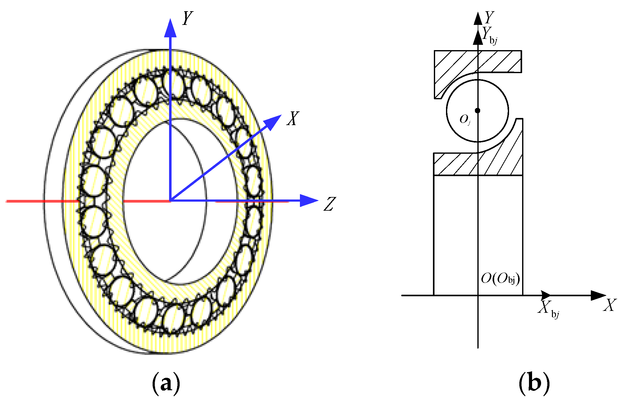
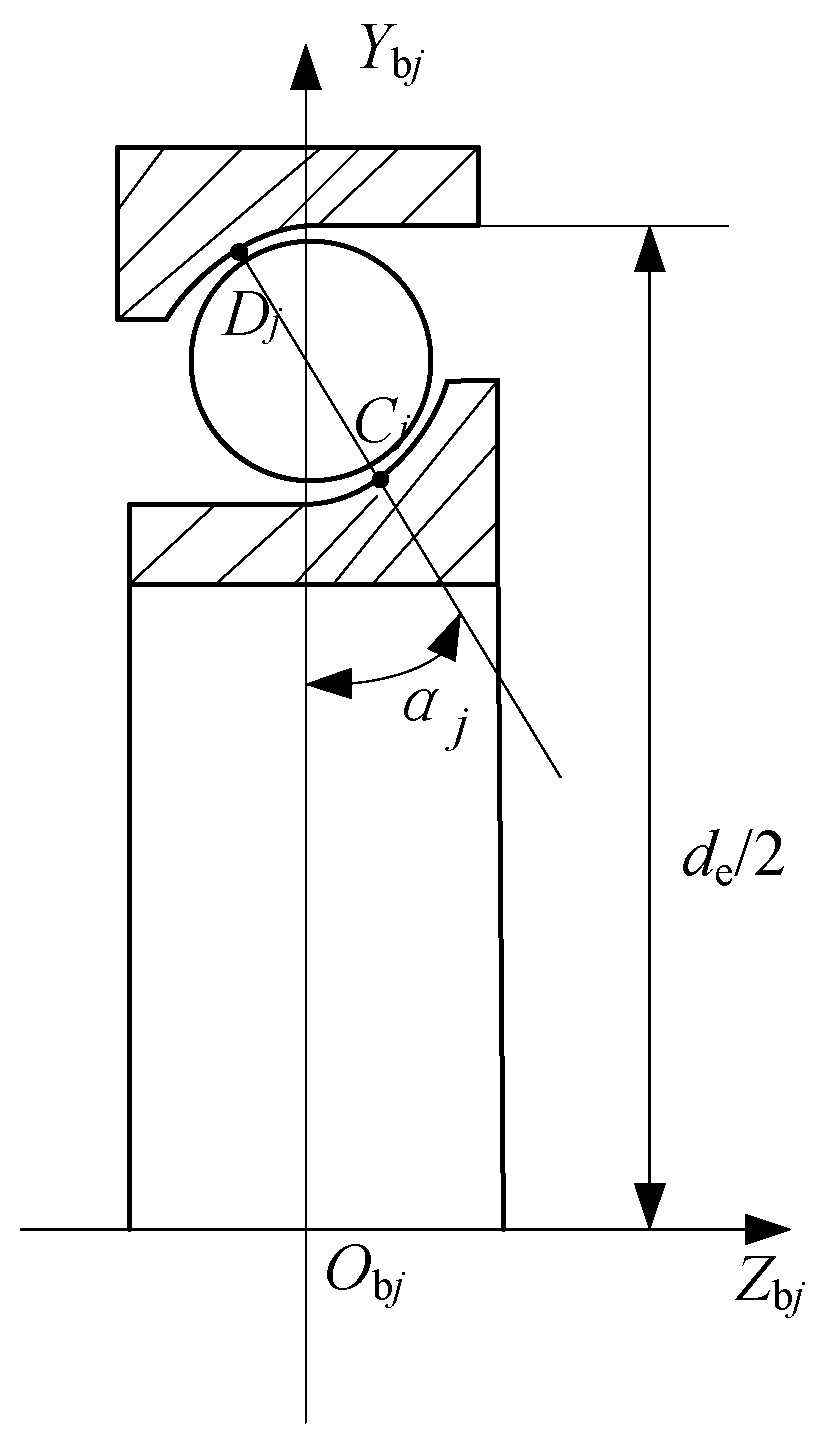
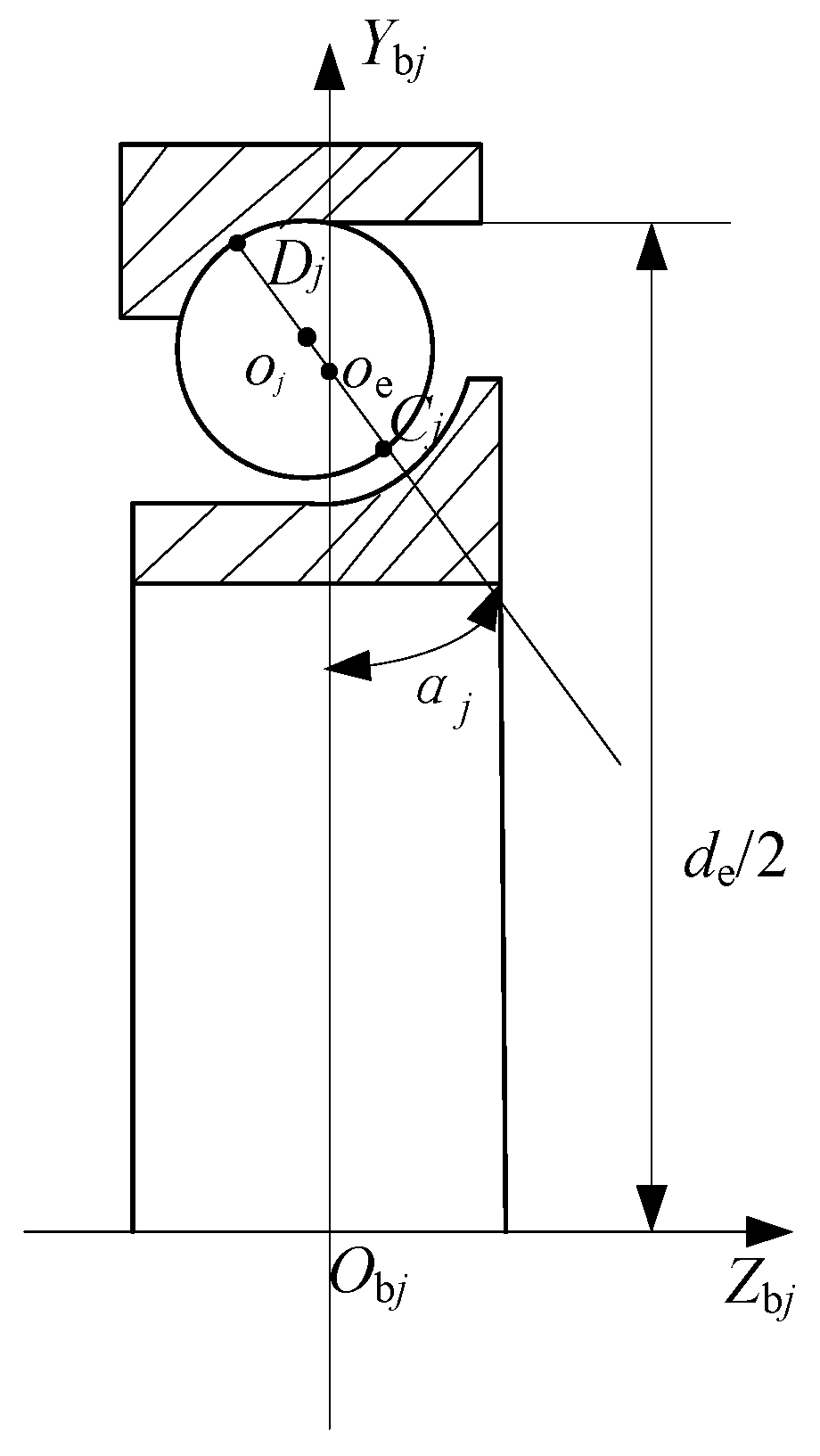
2.1. The Geometric and Kinematic Relationships of the Bearing

When the inner ring of the bearing is rotated counterclockwise at an angle α i , the balls rotate clockwise around their axes and are also rotated around the axis of the bearing [24]. The rotation angle, orbital angle, and position angle of the balls are as follows:
ω b = d m 2 D w 2 cos 2 α 2 d m D w α i
ω m = 0.5 α i ( 1 D w cos α / d m )
β j = 2 π ( j 1 ) / Z + ω m
where ω b , ω m are the angle of rotation and revolution of the balls,   d m is the diameter of the bearing pitch circle,   D w is the diameter of the balls,   α is the contact angle,   Z is the number of balls,   β j is the position angle of the j th ball, and where j is the serial number of the ball ( j = 1, 2, …, Z ).
The overall coordinate system of the bearing, XYZ, is fixed at the center of the outer ring. The local coordinate system Y b j O b j Z b j is fixed to the center of rotation of the outer ring, the Y b j axis passes through the center of rotation of the j th ball, as shown in Figure 1.

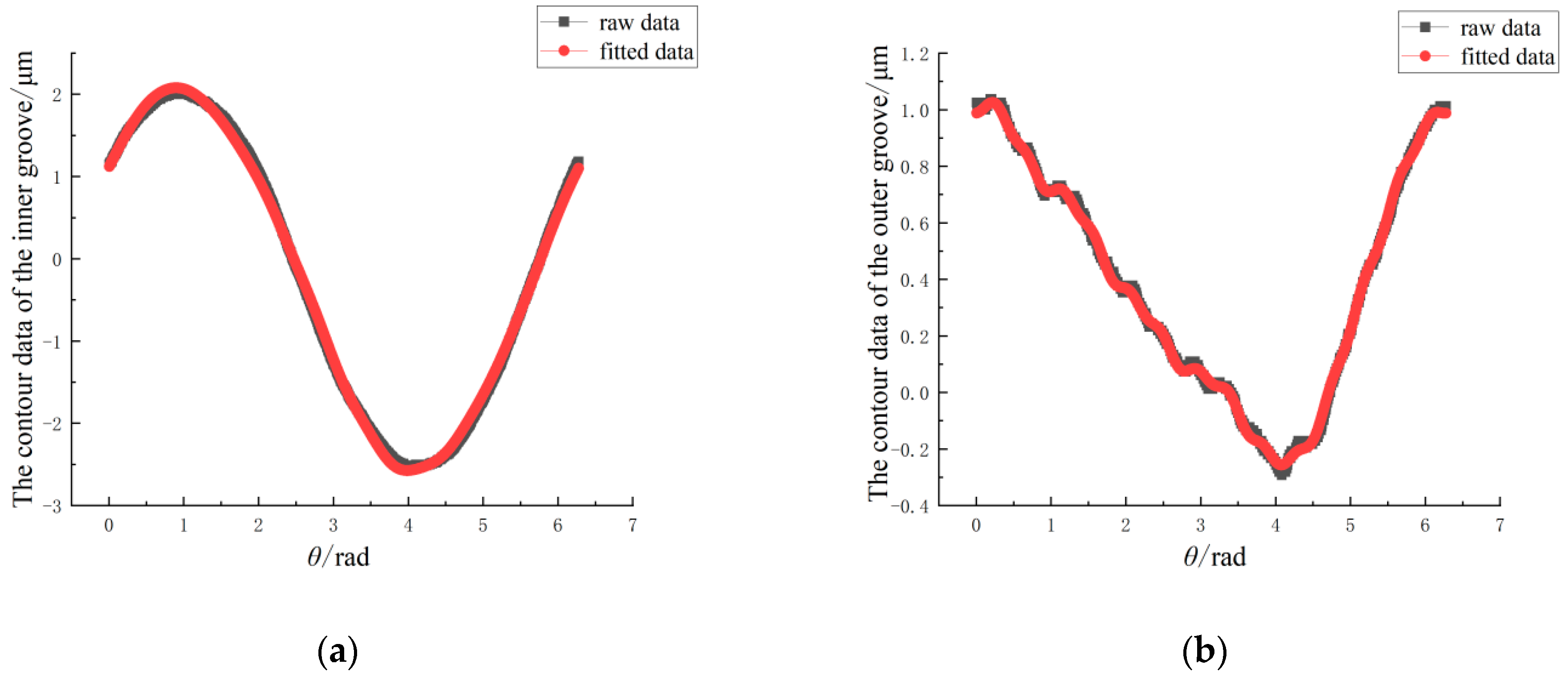
2.2. Equations of the Contour Curves of the Grooves

Fourier series is composed of a series of trigonometric functions and it is often used to characterize complex surface contours [25,26]. Here, the Fourier series is used to characterize the contour curves of the grooves, as shown in Equation (4).
Δ S ( θ ) = m = 2 C m cos ( m θ + ψ m )
where   S is roundness error of the grooves, m is the roundness error order, which characterizes the contour shape of the bearing parts, C m is the amplitude of the m th-order roundness error, which characterizes the peak value of the deviation of the contour of the bearing parts from the ideal circle, ψ m is the initial phase angle of the m th-order roundness error, and θ is the position angle.
The roundness error S i ( θ i ) of the inner groove and S e ( θ e ) of the outer groove are expressed as:
Δ S i ( θ i ) = m i = 2 C i m i cos ( m i ( θ i α i ) + ψ i m i ) Δ S e ( θ e ) = m e = 2 C e m e cos ( m e θ e + ψ e m e )
where   θ i is the position angle of any point on the inner groove, θ e is the position angle of any point on the outer groove, m i and m e are the roundness error orders of the inner and outer grooves, respectively, C i m i and C e m e are the amplitudes of the m i th-order and m e th-order roundness error, respectively, ψ i m i and ψ e m e are the phase angles of the m i th-order and m e th-order roundness error, respectively.
After considering the roundness error, the radius of curvature of the inner groove contour r i ( θ i ) , the radius of curvature of the outer groove contour r e ( θ e ) , as well as the diameters of the bottom of the inner groove contour d i ( θ i ) , and the bottom of the outer groove contour d e ( θ e ) are expressed as:
r i ( θ i ) = r i + Δ r i Δ S i ( θ i )
r e ( θ e ) = r e + Δ r e + Δ S e ( θ e )
d i ( θ i ) = d i + Δ d i + Δ S i ( θ i ) + Δ S i ( θ i + π )
d e ( θ e ) = d e + Δ d e + Δ S e ( θ e ) + Δ S e ( θ e + π )
where r i and r e are the radii of the curvature of the inner and outer grooves, respectively, Δ r i and Δ r e are the dimensional errors of the radii of the curvature of the inner and outer grooves, respectively, and d i , d e , Δ d i and Δ d e are the diameters of the bottom of the inner and outer grooves and their dimensional errors, respectively.

2.3. Coordinates of Contact Points on Grooves

The contact points on the grooves and the contact angles are changed due to the existence of the roundness error of the grooves and the dimensional error of the balls. The j th ball will be in contact with point C j on the inner groove and point D j on the outer groove if the j th ball can be in contact with both the inner and outer grooves. In the bearing, the positions of the expected contact points on the grooves and the j th ball in the axial plane are as shown in Figure 2. The position of the j th ball in the radial plane is as shown in Figure 3. The three-dimensional coordinates of C j and D j are expressed by the following derivation.
The coordinates of the center of curvature o i of the inner groove in the Y b j O b j Z b j are:
Y o i = d i / 2 + r i Z o i = 0
Similarly, the coordinates of the center of curvature o e of the outer groove in the Y b j O b j Z b j are:
Y o e = d e / 2 r e Z o e = 0
The contact angles are changed due to the existence of the roundness error of the grooves and the dimensional error of the balls. The contact angle of the j th ball is calculated by Equation (12).
α j = arccos 1 d e ( β j ) d i ( β j ) 2 ( D w + Δ D r j ) 2 ( r i ( β j ) + r e ( β j ) ( D w + Δ D r j ) )
where D r j is the dimensional error of the j th ball.
The distance from point D j on the outer groove to the center of curvature o e of the outer groove is equal to the sum of the outer groove radius of curvature and the roundness error at that point. The coordinates of point D j in the Y b j O b j Z b j plane are as follows:
Y D j = Y o e + r e ( β j ) cos α j Z D j = Z o e r e ( β j ) sin α j
On the overall coordinate system XYZ, the three-dimensional coordinates of point D j on the outer groove can be obtained:
X D j = ( Y o e + r e ( β j ) cos α j ) cos β j Y D j = ( Y o e + r e ( β j ) cos α j ) sin β j Z D j = Z o e r e ( β j ) sin α j
Similarly, the C j point on the inner groove can be expressed as:
X C j = ( Y o i r i ( β j ) cos α j ) cos β j Y C j = ( Y o i r i ( β j ) cos α j ) sin β j Z C j = Z o i + r i ( β j ) sin α j

2.4. Coordinates of the Center of the Balls

When the inner ring is rotated at a certain angle, all the balls are rotated to a new position and then moved to the outer groove until the balls contact the outer groove (as shown in Figure 4). Through the geometrical relationship of the bearing, the center coordinates of the j th ball in contact with the outer groove are obtained.
When the inner ring is rotated by an angle α i , the balls are rotated to a certain position. The j th ball is in contact with the outer groove point D j . The center o j of the ball and the curvature center o e of the outer groove are both on the contact normal D j o e . At this time, the distance between the two center points is calculated using Equation (16).
o e o j ¯ = D j o e ¯ D j o j ¯
where D j o j ¯ is the radius of the j th ball contour at this time, calculated using Equation (17). D j o e ¯ is the radius of curvature at point D j on the outer groove contour at this time.
D j o j ¯ = D w / 2 + Δ D r j / 2
D j o e ¯ = r e ( β j )
When the j th ball is in contact with the outer groove, the distance from the center of the ball to the curvature center of the outer groove is known. The coordinates of the center of the j th ball in the local coordinate system Y b j O b j Z b j are derived, according to the geometrical relationship (Equation (19)).
Z o j = Z o e o j o e ¯ sin α j Y o j = Y o e + o j o e ¯ cos α j
The coordinates of the center of the ball in the global coordinate system XYZ are deduced:
X o j = ( Y o e + o j o e ¯ cos α j ) cos β j Y o j = ( Y o e + o j o e ¯ cos α j ) sin β j Z o j = Z o e o j o e ¯ sin α j

2.5. Coordinates of the Rotation Center of the Inner Ring

In order to find the coordinates of the optimal rotation center of the inner ring, the inner ring needs to be translated in the direction of the ball, according to the set step size during the rotation process. Some balls will not be in contact with the inner groove due to the existence of the roundness error of the grooves and the dimensional error of the balls. At this time, when at any given position of the inner ring, there are three possible contact states between the inner groove and each ball: contact, separation, or interference. The contact state between the ball and the inner groove is determined by calculating the shortest distance between the surface of the ball and contact point C j   of the inner groove.
The inner ring is displaced in the X, Y, and Z directions and the coordinates of contact point C j on the inner groove are changed to:
X C j = ( Y o i r i ( β j ) cos α j ) cos β j + Δ x Y C j = ( Y o i r i ( β j ) cos α j ) sin β j + Δ y Z C j = Z o i + r i ( β j ) sin β j + Δ z
The coordinates of center O b j of the j th ball are known and the distance between the center of the ball and the contact point C j on the inner groove can be obtained. The difference between this distance and the radius of the ball contour is the distance between the surface of the ball and the contact point C j on the inner groove.
L = ( X o j X C j ) 2 + ( Y o j Y C j ) 2 + ( Z o j Z C j ) 2 ( D w + Δ D r j ) / 2
ε is set to the allowable interference error. When | L | < ε , the inner groove is in contact with the ball. When | L | > ε , the inner groove is separated from the ball. When | L | < ε , the inner groove interferes with the ball.
The contact state of the inner groove can be obtained under several inner ring positions and the stable position of the inner ring is determined from the criteria of the stable contact state of the inner ring. The stable position of the inner ring should meet the following criteria:
  • None of the balls interfered with the inner groove. When one ball interferes with the inner ring groove, it indicates that the position of the inner ring is not the stable position of the inner ring;
  • The number of balls that contacted the inner groove is not less than three. Owing to the point contact between the ball and the inner ring groove, the number of balls contacted in the inner groove must be more than or equal to three when the inner groove is in a stable state. Otherwise, the force on the inner ring will not be able to keep the inner ring stable.
  • The balls that made contact with the inner groove were distributed in at least three different quadrants or two symmetrical quadrants. When the contact balls are distributed in three different quadrants, each ball that made contact with the inner groove is equivalent to a fulcrum; three fulcrums located in three quadrants cause the inner ring to be in a stable state. When the contact ball is located in two quadrants, these quadrants must be symmetrical, i.e., either quadrants one and three or quadrants two and four.
Through the above criteria, the coordinates of the rotation center of the inner ring that satisfy the force balance constraints and geometric constraints are obtained. When there are multiple inner ring positions that satisfy the criteria, the average value will be used as the center coordinates of the inner ring.

3. Experimental Validation of the Prediction Model of the Inner Ring Runout of the Bearing

In order to verify the correctness of the above prediction model, five sets of ZYS-B7008C/P4 bearings were selected to carry out the measurement of the bearing parts and the measurement of the inner ring runout at the National Bearing Quality Inspection Center. The contour and roundness of the grooves, as well as the axial and radial runout of the inner ring, were measured.

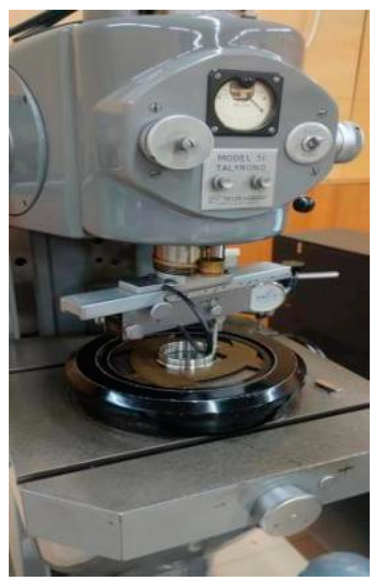
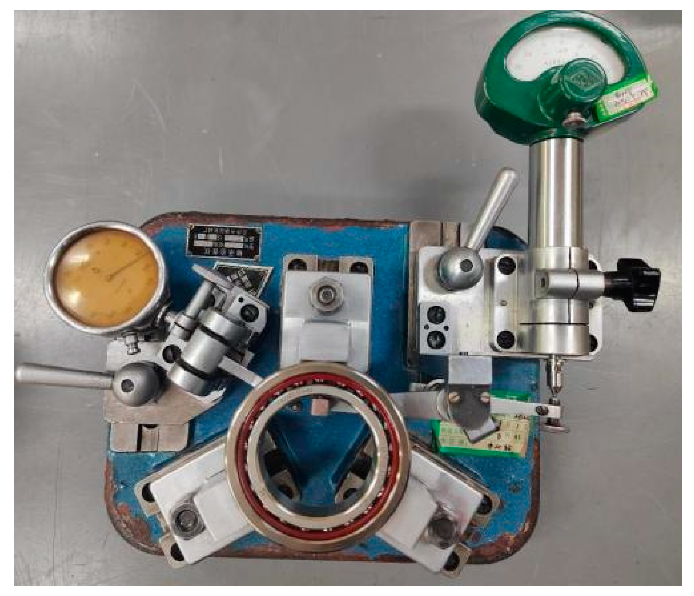
3.1. Measurement of the Contours and Roundness of the Grooves

The contours of the grooves were measured with the Talyrond Model 51 roundness gauge, as shown in Figure 5. During the measurement, the ring was fixed to the table and the measuring head was mounted on the rotating spindle and was in contact with the surface of the groove. The measuring head was driven by the rotating spindle for a week, and 1024 points on each groove were measured. The raw data of the measured contours were stored.
The raw data were subjected to spectral analysis to obtain the harmonic orders, amplitudes, and phase angles on the inner and outer grooves of the bearing. The harmonic components with the higher amplitudes were isolated for further investigation. Table 1 and Table 2 show the data for the middle cross-section of the measured B7008C-1 bearing, for example. The harmonic orders and their corresponding amplitudes and phase angles were substituted into Equation (4) to construct the equations of the contour curves of the grooves. The greater the selected harmonic components, the closer the fitted contour curves are to the actual contour.
A comparison of the fitted contour curves of the grooves with the original contour curves of the grooves is given in Figure 6, where it can be seen that the fitted contour curves of the grooves reflect the true contour curves well.
The roundness values of the measured cross-sections were determined by the difference between the maximum and minimum radius of the measured contours of the grooves, derived by the least squares method. The measured data are shown in Table 3. The roundness value of the outer groove is in the range of 0.28 μm~0.57 μm, and the variation of the roundness value at three positions of the outer groove is in the range of 0.02 μm~0.18 μm. The roundness value of the inner groove is in the range of 0.15 μm~0.57 μm, and the variation of the roundness value at three positions of the inner groove is in the range of 0.03 μm~0.07 μm.

3.2. Measurement of the Inner Ring Runout and Validation of the Prediction Model

Measurement of the inner ring runout of the bearing was carried out on the assembled bearings using the B024 bearing inner ring runout gauge, as shown in Figure 7. The axial and radial runouts of the inner ring of the measured bearings were measured. The measurement principle is shown in Figure 8. During measurement, the outer ring of the bearing is fixed and the small axial load a is applied to the inner ring. The two measuring heads of the instrument are in contact with the inner circular surface and the end face of the inner ring. The inner ring is rotated for several weeks and the axial and radial runouts of the inner ring are determined according to the maximum and minimum values on the micrometers of the gauge.
The structural parameters of the bearings as well as the dimensional differences of the balls were also measured, as shown in Table 4.
The structural parameters and the fitted equations of the contour curves of the grooves were substituted into the prediction model and the predicted values of the inner ring runout of the measured bearings were obtained. Taking the measured B7008C-1 bearing as an example, in the model, the inner ring is rotated 1° per step and rotated for one week. The minimum displacement of the center of the inner ring in the axial direction is obtained as 0.20205 mm and the maximum displacement is 0.20405 mm, meaning that the predicted value of the axial runout is 2.00 μm. In the radial direction, the minimum displacement of the center of the inner ring is 0.00072 mm and the maximum displacement is 0.00184 mm; therefore, the predicted value of the radial runout is 1.12 μm.
The measurement results and the model prediction results are shown in Table 5. From the tabular data, it can be seen that the prediction results were close to the measurement results, which verified the correctness of the prediction model established in this paper.

4. Results and Analysis

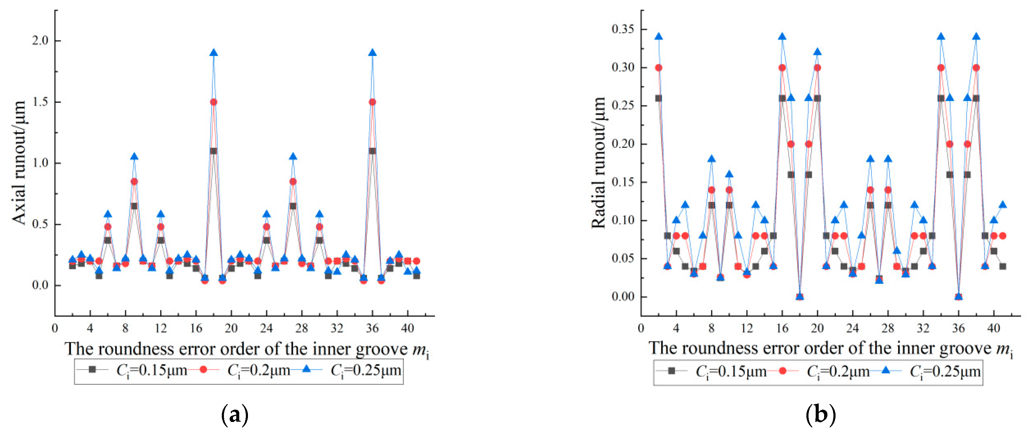
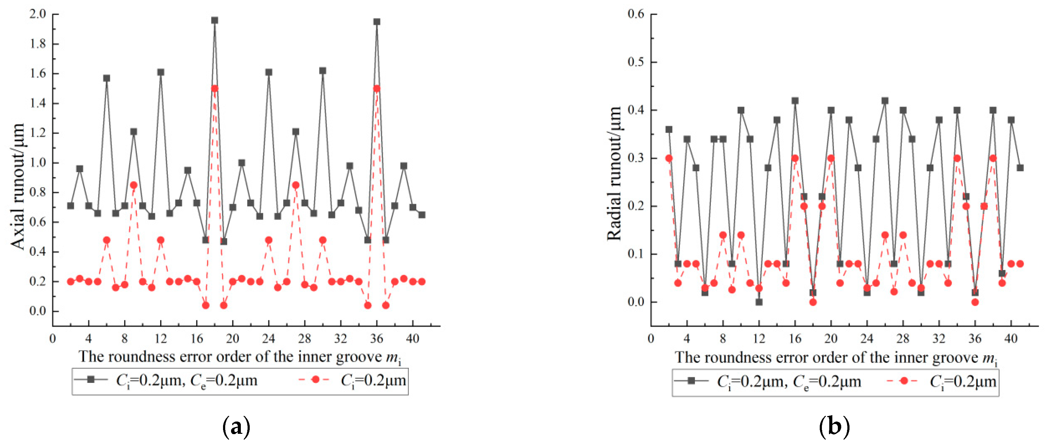
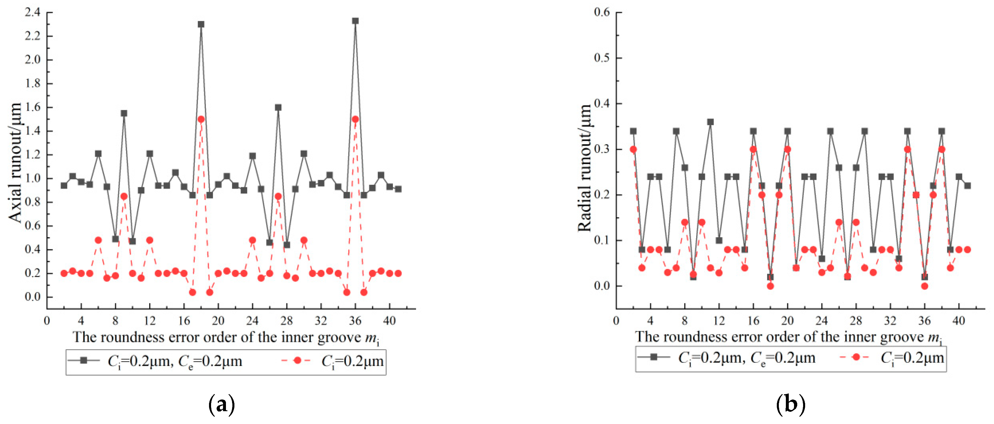
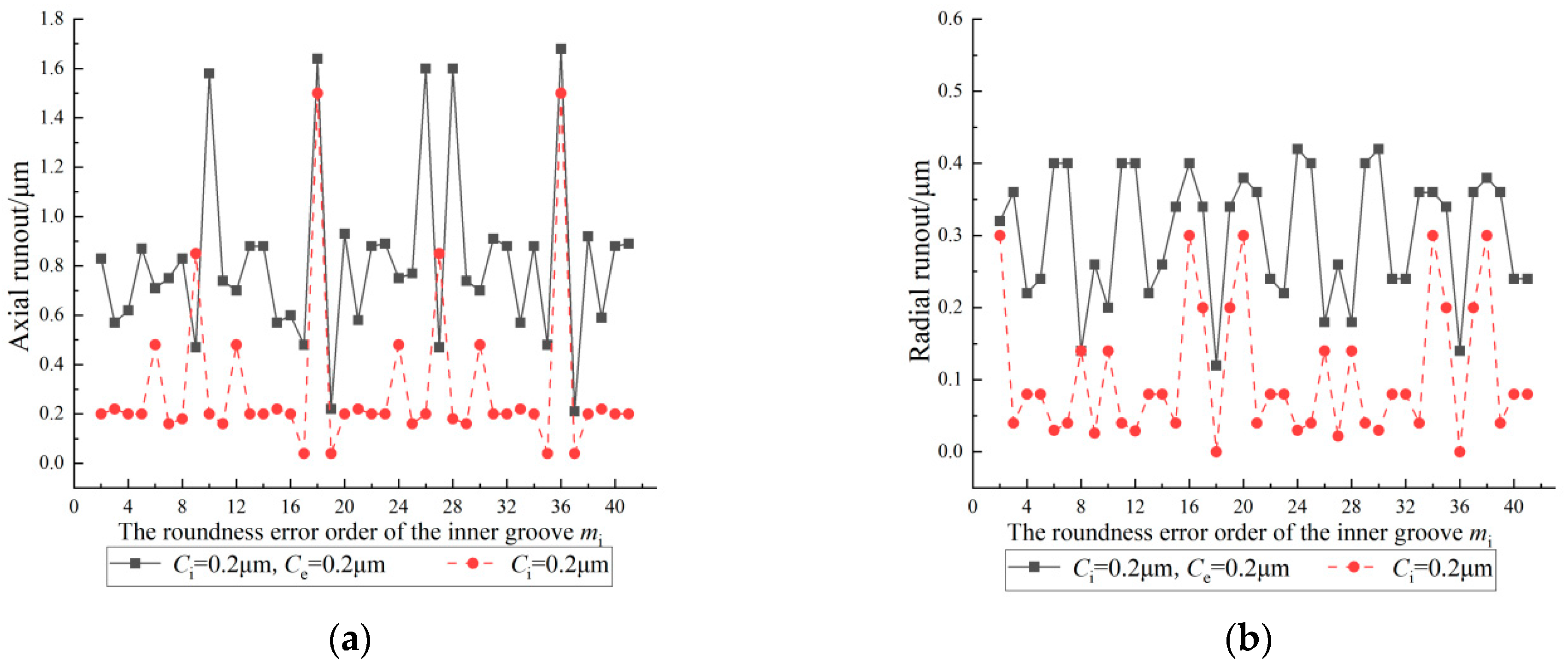
4.1. Effect of the Roundness Error Order of the Inner Groove on the Inner Ring Runout

Figure 9 shows the effect of the roundness error order of the inner groove on the inner ring runout. In the figure, the number of balls Z is 18 and the roundness error amplitudes of the inner groove are 0.15 μm, 0.2 μm, and 0.25 μm. From the figure, it can be seen that the axial runout and the radial runout of the inner ring show periodic changes with changes to the roundness error order of the inner groove; the period is Z . For the axial runout, when the roundness error order is n Z ( n is a positive integer), the axial runout increases significantly and reaches the maximum value. The ratio of the runout value to the roundness error amplitude value (referred to as the magnification) is between 7.33 and 7.6. When the roundness error order is n Z /3 ( n is a positive integer and is not a multiple of 3), the axial runout reaches a peak value, and the magnification is between 2.32 and 2.47. When the roundness error order is n Z /2 ( n is an odd positive integer), the axial runout reaches a larger peak value and the magnification is between 4.2 and 4.33. In the remaining cases, the magnification of the axial runout is between 0.28 and 1.14.
For the radial runout, when the roundness error order is ( n Z /2 ± 1) (n is a positive integer), the radial runout reaches a peak value: the magnification is between 0.6 and 0.88 when n is an odd positive integer, and between 1 and 1.07 when n is an even positive integer. When the roundness error order is (nZ ± 2) (n is a positive integer), the radial runout reaches the maximum value and the magnification is between 1.36 and 1.73. When the roundness error order is n Z /3 (n is a positive integer other than a multiple of 3) or n Z /2 (n is an odd positive integer), the radial runout decreases to a low value. When the roundness error order is n Z (n is a positive integer), the radial runout is 0 μm and achieves the minimum value. In the rest of the order cases, the magnification of the radial runout is between 0 and 0.53.
After considering the effect of the roundness error order of the inner groove on the inner ring runout, it was found that when the roundness error order of the inner ring has the specific relationship with the number of balls, the magnification of the axial runout or radial runout of the inner ring of the bearing changed significantly. Therefore, the roundness error order of the inner groove should be distributed in reasonable intervals by utilizing the harmonic control theory. The inner ring runout can be effectively reduced by avoiding these specific roundness error orders.

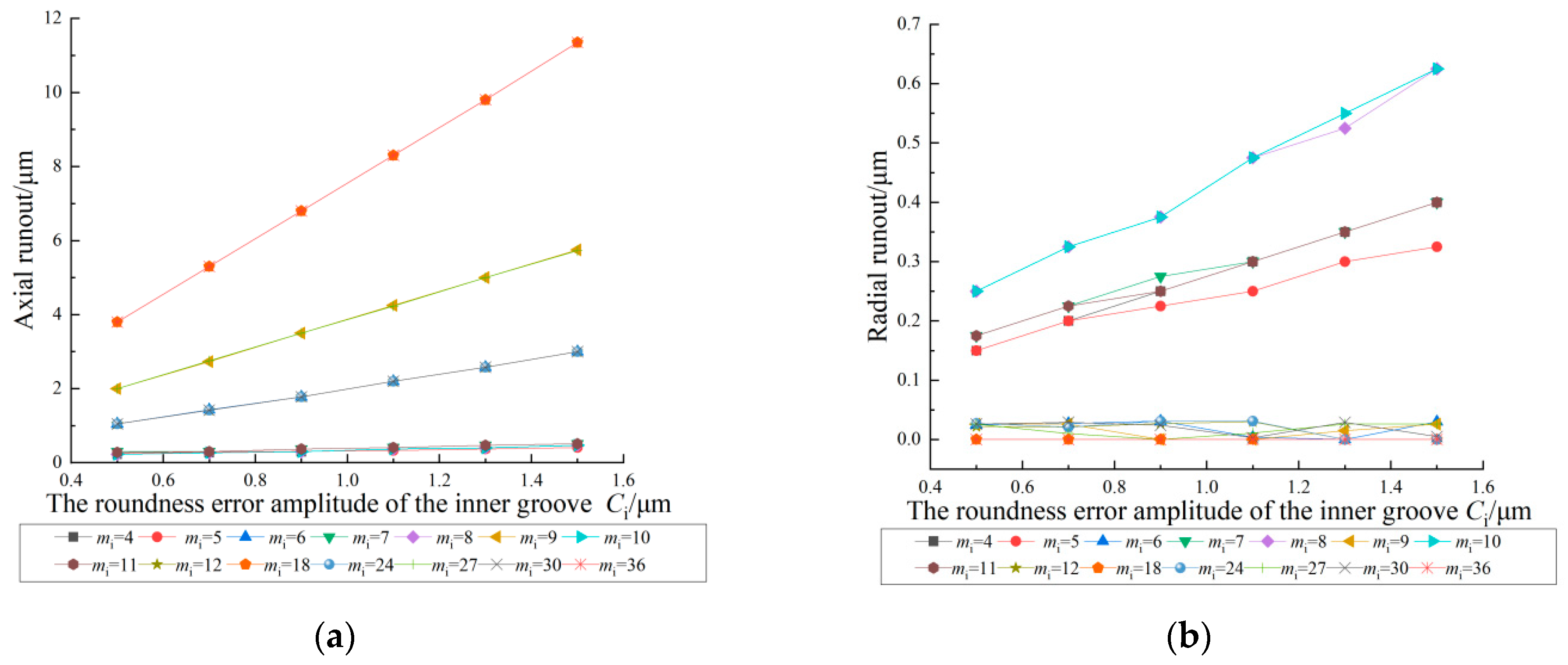
4.2. Effect of the Roundness Error Amplitude of the Inner Groove on the Inner Ring Runout

Figure 10 shows the effect of the roundness error amplitude of the inner groove on the inner ring runout. In the figure, the number of balls Z is 18, the roundness error orders of the inner groove are 4, 5, 6, 7, 8, 9, 10, 11, 12, 18, 24, 27, 30, and 36, and the roundness error amplitude of the inner groove varies in the range of 0.5 to 1.5 μm. As shown in the figure, when the roundness error orders are 4, 5, 7, 8, 10, and 11, the inner ring runout increases with an increase in the roundness error amplitudes of the inner groove. The magnifications of the axial runout are distributed between 0.3 and 0.5 and the magnifications of the radial runout are distributed between 0.21 and 0.5. When the roundness error orders are n Z /3 (n is a positive integer other than a multiple of 3), n Z /2 (n is an odd positive integer), and n Z (n is a positive integer), the axial runout increases significantly with an increase in the roundness error amplitudes of the inner groove. The magnifications range from 1.94 to 2.1, 3.83 to 4.0, and 7.53 to 7.6, respectively. The radial runout does not change with an increase in the roundness error amplitude of the inner groove and the magnifications of the radial runout fluctuate only slightly between 0 and 0.05 when the roundness error order is n Z /3 or n Z /2. There is no radial runout when the roundness error order is n Z .
These results show that the effect of the roundness error amplitude of the inner groove on the inner ring runout is significant. This is because the increase in the roundness error amplitude increases the distance between the peaks and valleys of the groove, the center of the inner ring displacement is increased, and the runout of the inner ring is obvious. Therefore, the inner groove runout can be reduced by appropriately reducing the roundness error amplitude of the inner groove. However, when the roundness error orders are n Z /3 (n is a positive integer other than a multiple of 3), n Z /2 (n is an odd positive integer), and n Z (n is a positive integer), the radial runout is relatively stable and not easily affected by the roundness error amplitude of the inner groove.

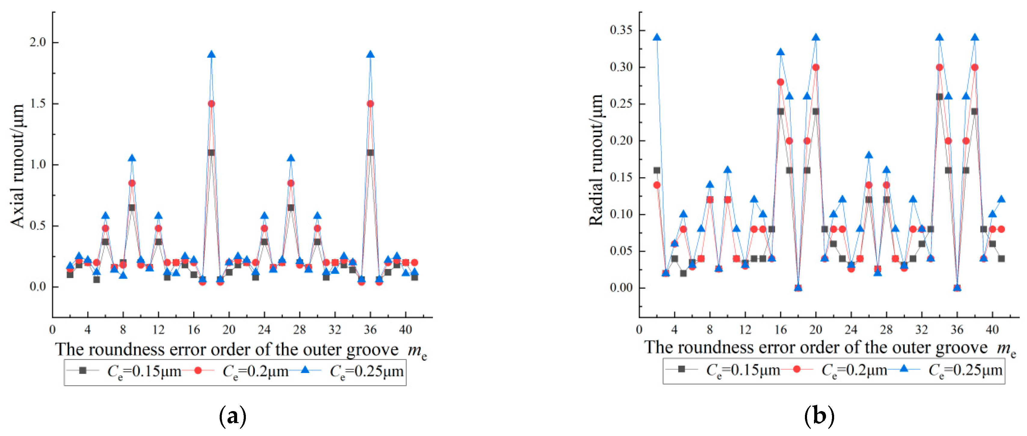
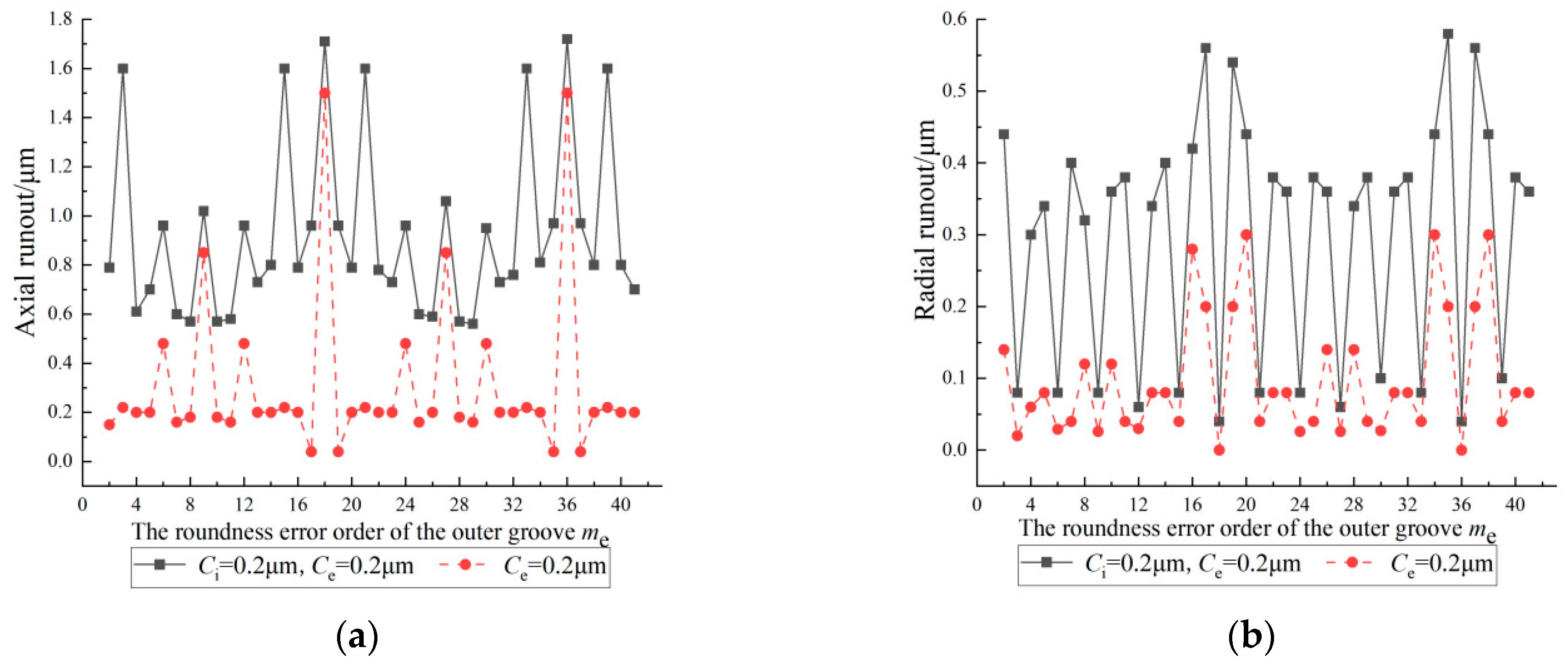
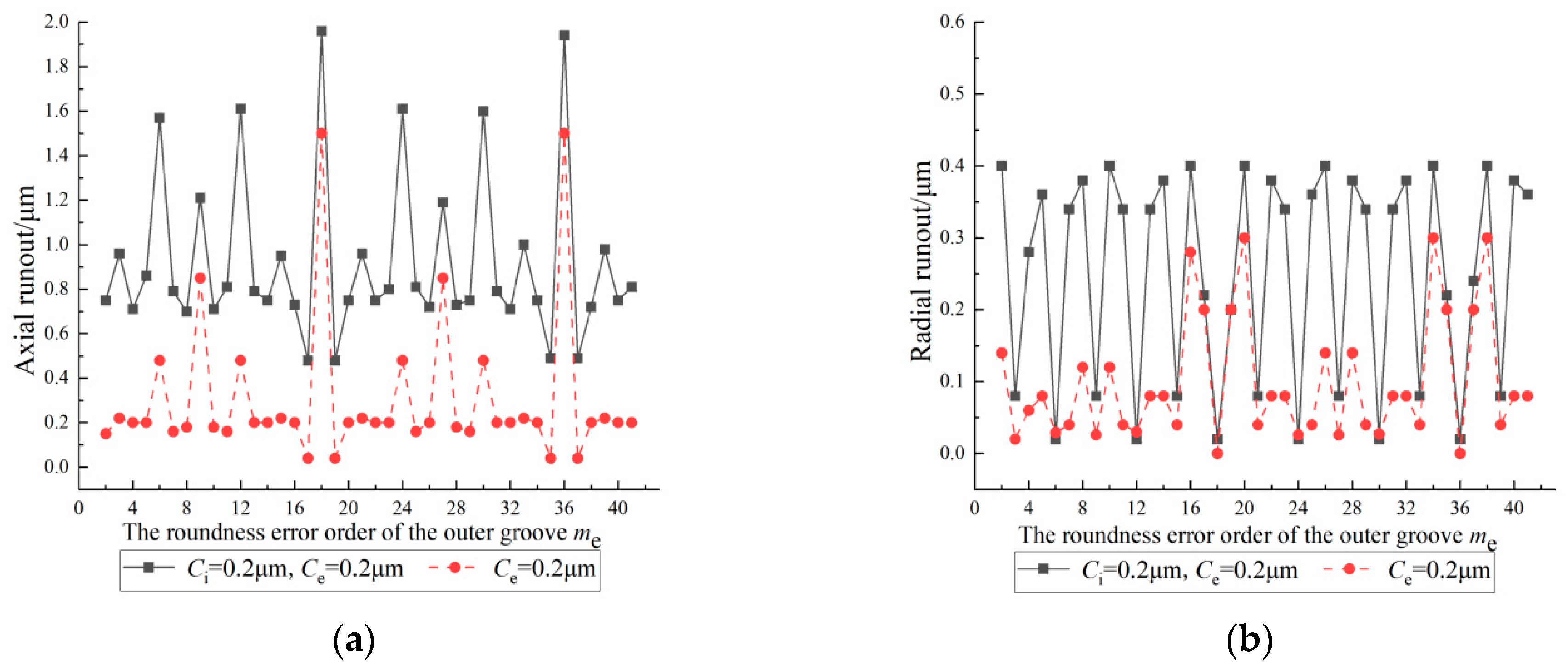
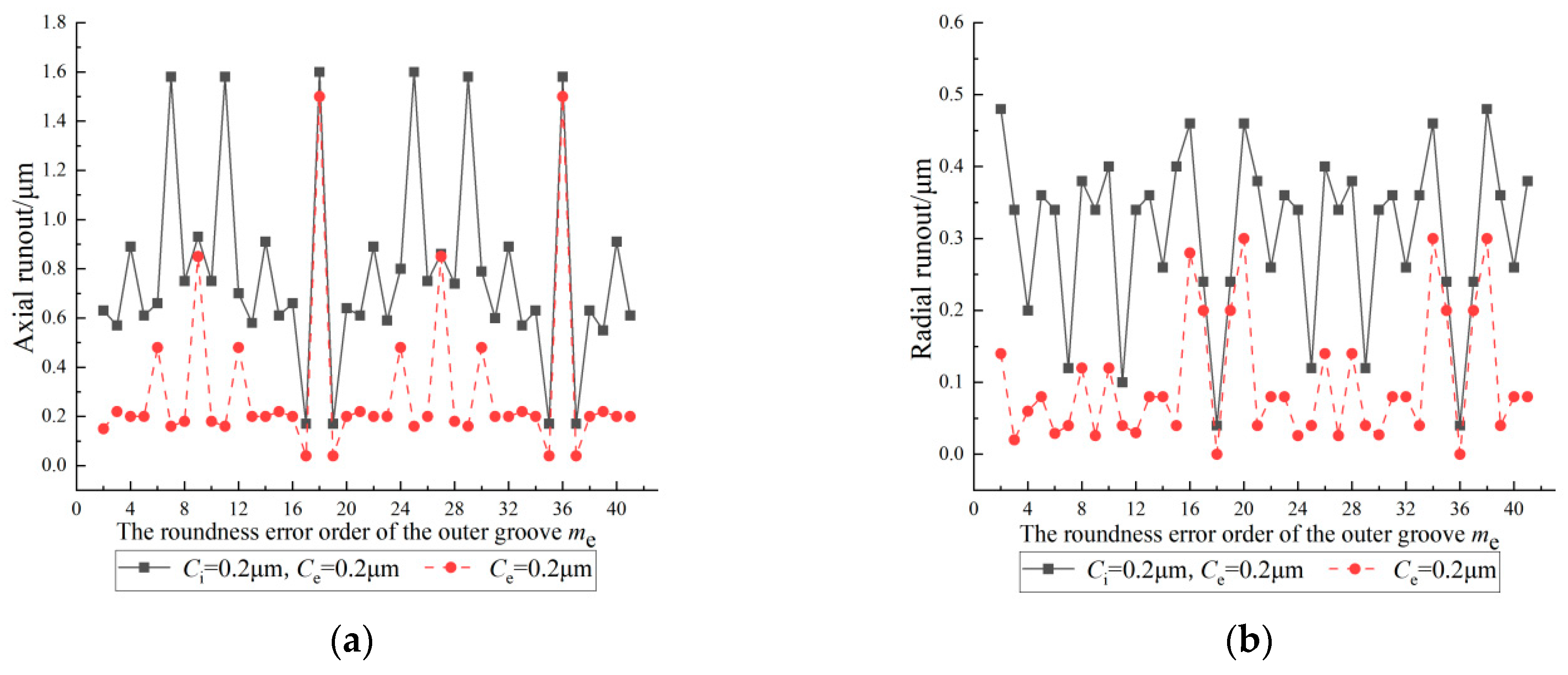
4.3. Effect of the Roundness Error Order of the Outer Groove on the Inner Ring Runout

Figure 11 shows the effect of the roundness error order of the outer groove on the inner ring runout. In the figure, the number of balls Z is 18 and the roundness error amplitudes of the outer groove are 0.15 μm, 0.2 μm, and 0.25 μm. From the figure, it can be seen that the roundness error order of the outer groove and the roundness error order of the inner groove have the same effect on the inner ring runout. When the roundness error orders are n Z /3 (n is a positive integer other than a multiple of 3), n Z /2 (n is an odd positive integer), and n Z (n is a positive integer) in these specific orders, the magnifications of the axial runout increase significantly. When the roundness error orders are ( n Z /2 ± 1), (nZ ± 2) (n is a positive integer) in these specific orders, the magnifications of the radial runout increase significantly. Therefore, the roundness error order of the outer groove should also be controlled in reasonable intervals to reduce the inner ring runout of the bearing.

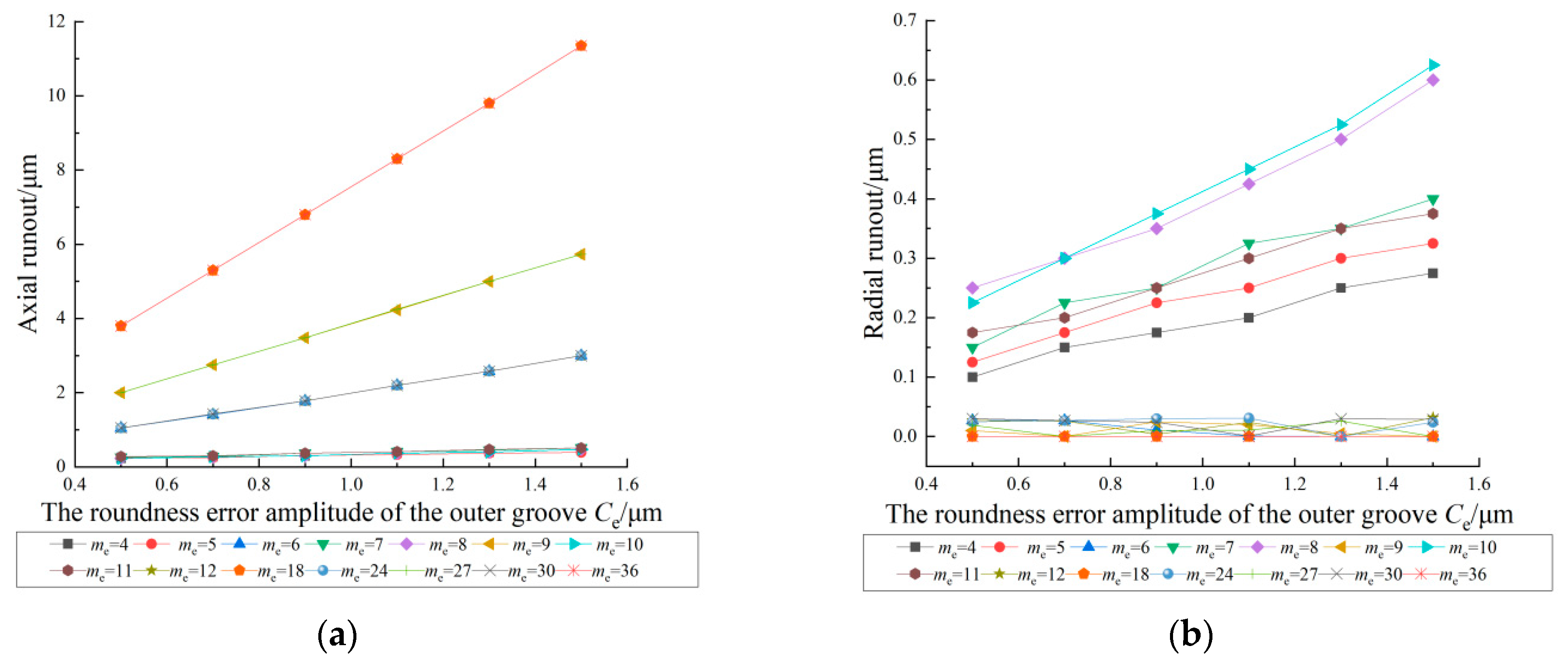
4.4. Effect of the Roundness Error Amplitude of the Outer Groove on the Inner Ring Runout

Figure 12 shows the effect of the roundness error amplitude of the outer groove on the inner ring runout. In this case, the number of balls Z is 18 and the roundness error orders of the outer groove are 4, 5, 6, 7, 8, 9, 10, 11, 12, 18, 24, 27, 30, and 36, and the roundness error amplitude of the outer groove varies in the range of 0.5 to 1.5 μm. From the figure, it can be seen that the roundness error amplitude of the outer groove and the roundness error amplitude of the inner groove have the same effect on the inner ring runout. The inner ring runout increases with an increase in the roundness error amplitude of the outer groove. When the roundness error orders are n Z /3 (n is a positive integer other than a multiple of 3), n Z /2 (n is an odd positive integer), and n Z (n is a positive integer), the magnifications of the axial runout increase significantly with an increase in the roundness error amplitude, but the magnifications of the radial runout do not change with an increase in roundness error amplitude. When the roundness error orders are n Z /3 and n Z /2, the radial runout is obviously reduced and only a slight radial runout is produced. There is no radial runout when the roundness error order is n Z .
These results show that the effect of the roundness error amplitude of the outer groove on the inner ring runout is significant. Therefore, the inner ring runout can also be reduced by appropriately reducing the roundness error amplitude of the outer groove.

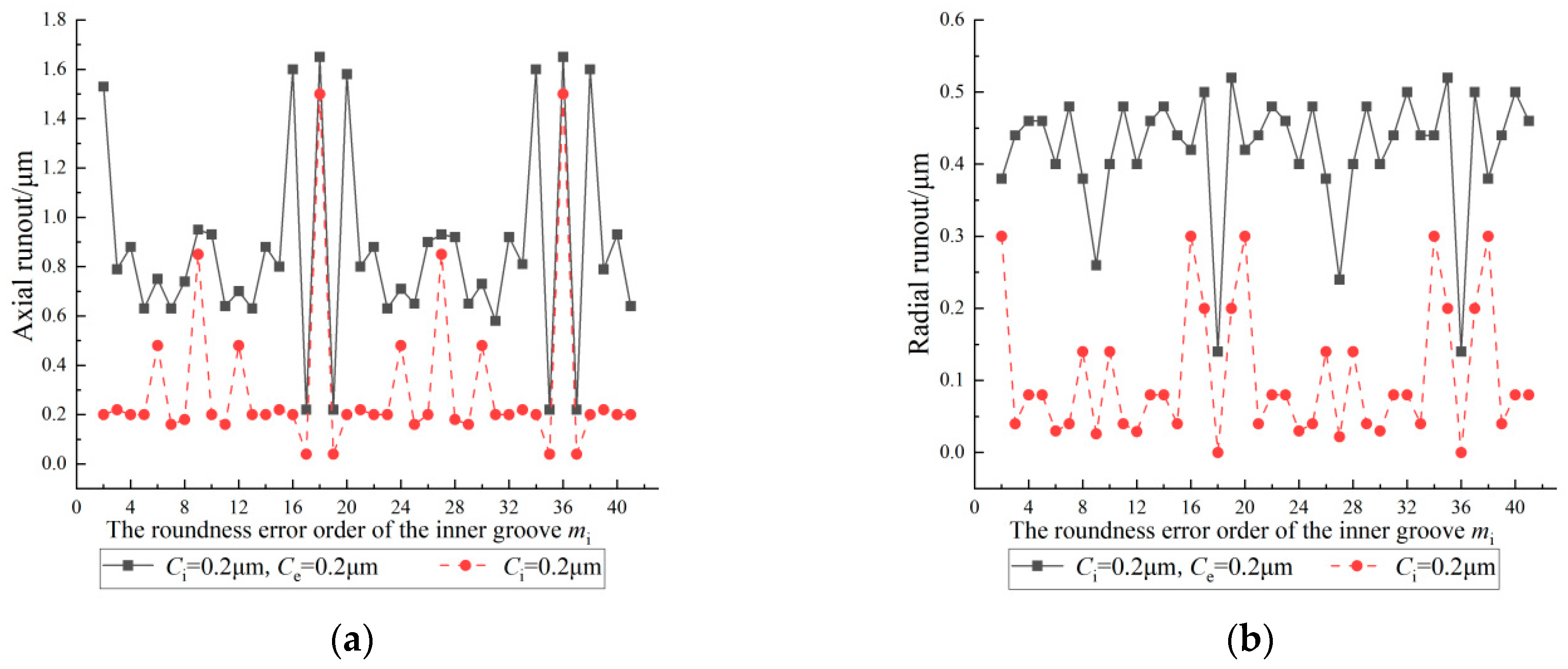
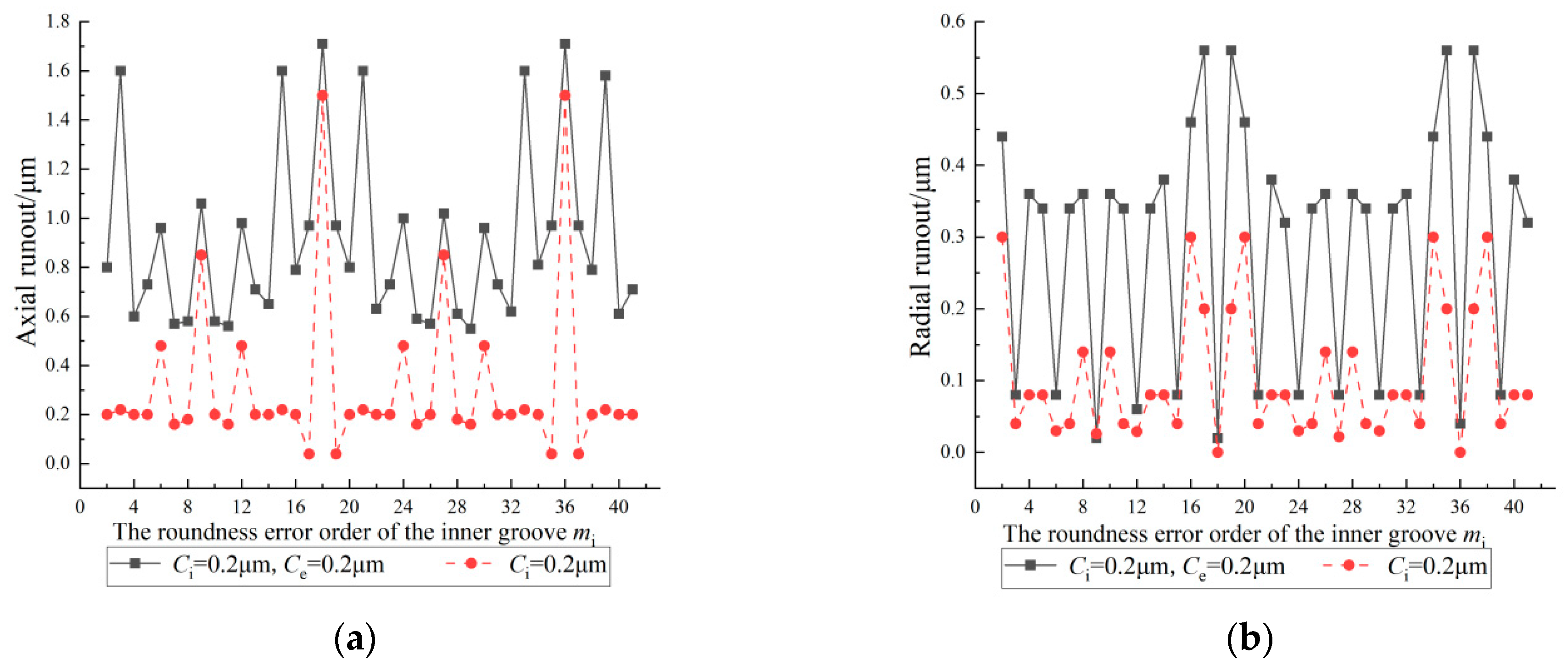
4.5. Coupling Effect of the Roundness Error of the Inner and Outer Grooves on the Inner Ring Runout

Figure 13, Figure 14, Figure 15, Figure 16, Figure 17, Figure 18, Figure 19, Figure 20, Figure 21, Figure 22, Figure 23 and Figure 24 show the coupling effect of the roundness error of the inner and outer grooves on the inner ring runout. In this case, the number of balls Z is 18 and the roundness error amplitude of both the inner and outer grooves is 0.2 μm. Figure 13, Figure 14, Figure 15, Figure 16, Figure 17 and Figure 18 show that the roundness error orders of the outer groove are 2, 3, 6, 7, 9, and 10, and the range of the roundness error order of the inner groove is 2~41. Figure 19, Figure 20, Figure 21, Figure 22, Figure 23 and Figure 24 show that the roundness error orders of the inner groove are 2, 3, 6, 7, 9, and 10, and the range of the roundness error order of the outer groove is 2~41. It can be seen that under the coupling effect of the roundness error of the inner and outer grooves, the inner ring runout shows a periodic change with the period of Z . In addition, compared with the effect of the roundness error of a single groove, the magnifications of the inner ring runout increase as a whole when the roundness error of the inner and outer grooves are coupled.
From Figure 13, Figure 14, Figure 15, Figure 16, Figure 17 and Figure 18, it can be seen that when the roundness error order of the inner groove is n Z (n is a positive integer), the axial runout reaches the maximum value and the radial runout reaches the minimum value. When the roundness error order of the inner groove is the same as that of the outer groove, the axial runout rises to a peak value, while the radial runout decreases. When the roundness error order of the inner groove is ( n Z ± m e ), the axial runout rises to a peak value again and the radial runout decreases to a low point. When the roundness error order of the inner groove is ( n Z ± 1) or ( n Z ± 2) (n is a positive integer), the radial runout increases significantly and reaches the maximum value.
From Figure 19, Figure 20, Figure 21, Figure 22, Figure 23 and Figure 24, it can be seen that when the roundness error order of the outer groove is n Z (n is a positive integer), the axial runout reaches the maximum value and the radial runout reaches the minimum value. When the roundness error order of the outer groove is the same as that of the inner groove, the axial runout rises to a peak value while the radial runout decreases. When the roundness error order of the outer groove is ( n Z ± m i ), the axial runout rises to a peak value again and the radial runout decreases to a low point. When the roundness error order of the outer groove is ( n Z ± 1) or ( n Z ± 2) (n is a positive integer), the radial runout increases significantly and reaches the maximum value.

5. Conclusions

In order to find the effect law of the roundness error of the grooves on the inner ring runout of the angular contact ball bearings, a prediction model of the inner ring runout of the bearing is established. The effects of the order and amplitude of the roundness error of the inner groove and the order and amplitude of the roundness error of the outer groove on the inner ring runout are analyzed. The coupling effect of the roundness error of the inner and outer grooves on the inner ring runout is further analyzed. The results show that:
  • The inner ring runout changes periodically with a change in the roundness error order of the grooves; the period is the number of balls.
  • The inner ring runout increases with an increase in the roundness error amplitude and the roundness error order affects the magnitude of the increase.
  • Under the coupling of the roundness error of the inner and outer grooves, the magnification of the inner ring runout increases as a whole.
  • When there are specific relationships between the roundness error orders of the grooves and the number of balls, the magnification of the axial or radial runout changes significantly.
According to the tolerance ranges in which the geometric errors of the bearing parts are located, the bearing parts can be classified into different accuracy levels. Obviously, the bearings assembled with bearing parts of different accuracy levels have different accuracy levels. Therefore, a prediction model for the distribution of the rotational accuracy of angular contact ball bearings will be developed in the future to study the dependent relationship between the distribution of the geometric error of the bearing parts and the distribution of the rotational accuracy of the bearings.

Author Contributions

Conceptualization, D.C.; methodology, D.C.; validation, D.C.; resources, Y.Y.; writing—original draft, D.C.; writing—review & editing, Y.Y., Y.X. and H.H.; supervision, H.C.; project administration, P.G. All authors have read and agreed to the published version of the manuscript.

Funding

This work was supported by the Special Project of the Ministry of Industry and Information Technology (Approval No. TC220H05V), the Open Fund Program of Henan Provincial Key Laboratory of High-Performance Bearing Technology (Approval No. ZYSKF202408), and the Key Scientific Research Project of Higher Education Institutions in Henan Province (Approval No. 22A460018).

Data Availability Statement

The authors confirm that the data supporting the findings of this study are available within the article.

Conflicts of Interest

Pengge Guo is employed by Luoyang Bearing Group Company Ltd., which has no role in the design of the study; in the collection, analyses, or interpretation of data; in the writing of the manuscript, or in the decision to publish the results. The authors declare no conflicts of interest.

References

  1. Li, X.; Yu, K.; Ma, H.; Cao, L.; Luo, Z.; Li, H.; Che, L. Analysis of varying contact angles and load distributions in defective angular contact ball bearing. Eng. Fail. Anal. 2018, 91, 449–464. [Google Scholar] [CrossRef]
  2. Bodewig, A.H.; Pape, F.; Poll, G. Optimizing Stainless Steel Bearings: Enhancement of Stainless Steel Bearing Fatigue Life by Low-Temperature Forming. Metals 2024, 14, 512. [Google Scholar] [CrossRef]
  3. Pape, F.; Coors, T.; Wang, Y.; Poll, G. Fatigue Life Calculation of Load-Adapted Hybrid Angular Contact Ball Bearings; Springer: Singapore, 2019; pp. 401–414. [Google Scholar]
  4. Takabi, J.; Khonsari, M. On the thermally-induced seizure in bearings: A review. Tribol. Int. 2015, 91, 118–130. [Google Scholar] [CrossRef]
  5. Gao, S.; Wang, L.; Zhang, Y. Modeling and dynamic characteristic analysis of high speed angular contact ball bearing with variable clearance. Tribol. Int. 2023, 182, 108330. [Google Scholar] [CrossRef]
  6. Singh, S.; Howard, C.Q.; Hansen, C.H. An extensive review of vibration modelling of rolling element bearings with localised and extended defects. J. Sound Vib. 2015, 357, 300–330. [Google Scholar] [CrossRef]
  7. Rejith, R.; Kesavan, D.; Chakravarthy, P.; Murty, S.N. Bearings for aerospace applications. Tribol. Int. 2023, 181, 108312. [Google Scholar] [CrossRef]
  8. Noguchi, S.; Tanaka, K.; Ono, K. Theoretical analysis of a ball bearing used in HDD spindle motors for reduction of NRRO. IEEE Trans. Magn. 1999, 35, 845–850. [Google Scholar] [CrossRef]
  9. Noguchi, S.; Ono, K. Reduction of NRRO in ball bearings for HDD spindle motors. Precis. Eng. 2004, 28, 409–418. [Google Scholar] [CrossRef]
  10. Noguchi, S.; Obinata, S.; Saito, Y.; Akamatsu, Y.; Sakaguchi, T. The influence of the unequal orbital intervals of balls on the NRRO of rotational frequency of the cage in a ball bearing. Toraibarojisuto/J. Jpn. Soc. Tribol. 2005, 50, 90–96. [Google Scholar]
  11. Okamoto, J. Study on run-out of ball bearings-relation between unroundness of race and locus of shaft in rotation. J. Jpn. Soc. Tribol. 2001, 46, 578–584. [Google Scholar]
  12. Tada, S. Three-dimensional analysis of non-repeatable runout (NRRO) in ball bearing. KOYO Eng. J. 2002, 161, 31–37. [Google Scholar]
  13. Yang, Z.; Hong, J.; Liu, J.; Zhu, Y. Theoretical model to analyze the non-repetitive run-out (NRRO) of ball bearings. Adv. Sci. Lett. 2011, 4, 2522–2527. [Google Scholar] [CrossRef]
  14. Yang, Z.; Hong, J.; Liu, J.; Ding, Y.; Wang, M.Y. Theoretical method to reduce the non-repetitive run-out (NRRO) of angular contact ball bearings. In Proceedings of the 2011 IEEE International Symposium on Assembly and Manufacturing (ISAM), Tampere, Finland, 25–27 May 2011; pp. 1–6. [Google Scholar]
  15. Chen, G.; Wang, B.; Mao, F. Effects of raceway roundness and roller diameter errors on clearance and runout of a cylindrical roller bearing. Proc. Inst. Mech. Eng. Part J J. Eng. Tribol. 2013, 227, 275–285. [Google Scholar] [CrossRef]
  16. Ma, F.; Ji, P.; Li, Z.; Wu, B.; An, Q. Influences of off-sized rollers on mechanical performance of spherical roller bearings. Proc. Inst. Mech. Eng. Part K J. Multi-Body Dyn. 2015, 229, 344–356. [Google Scholar] [CrossRef]
  17. Yu, Y.; Chen, G.; Li, J.; Xue, Y.; Pang, B. Prediction Method for the Radial Runout of Inner Ring in Cylindrical Roller Bearings. Math. Probl. Eng. 2017, 2017, 6584561. [Google Scholar] [CrossRef]
  18. Yu, Y.; Chen, G.; Li, J.; Xue, Y. A method to predict the radial runout of outer ring in cylindrical roller bearings. Adv. Mech. Eng. 2017, 9, 168781401773325. [Google Scholar] [CrossRef]
  19. Yu, Y.; Li, J.; Xue, Y. Influence of roundness errors of bearing components on rotational accuracy of cylindrical roller bearings. Sci. Rep. 2022, 12, 6794. [Google Scholar] [CrossRef]
  20. Zha, J.; Chen, Y.; Zhang, P. Relationship between elliptical form error and rotation accuracy of hydrostatic journal bearing. Ind. Lubr. Tribol. 2017, 69, 905–911. [Google Scholar] [CrossRef]
  21. Hu, G.; Chen, Y.; Cui, L.; Jin, G.; Wang, T.; Qi, H.; Tian, Y. Investigation on modeling and formation mechanism of dynamic rotational error for spindle-rolling bearing system. Appl. Sci. 2020, 10, 5753. [Google Scholar] [CrossRef]
  22. Zhang, X.; Meng, Q.; Ma, J.; Zhang, Y.; Wen, B.; Guo, Z. Rotation Accuracy Analysis of High-speed Angular Contact Ball Bearings. Des. Eng. 2020, 38–49. Available online: https://www.semanticscholar.org/paper/Rotation-Accuracy-Analysis-of-High-speed-Angular-Xu-Qingguo/b91bb1ee79a91c732b734927e9f3f4bef1605dae (accessed on 31 July 2024). [CrossRef]
  23. Zhang, P. Accuracy prediction and roller number optimization of journal roller bearing based on averaging coefficient considering raceway roundness error. J. Braz. Soc. Mech. Sci. Eng. 2023, 45, 203. [Google Scholar] [CrossRef]
  24. Wang, W.; Hu, L.; Zhang, S.; Zhao, Z.; Ai, S. Modeling angular contact ball bearing without raceway control hypothesis. Mech. Mach. Theory 2014, 82, 154–172. [Google Scholar] [CrossRef]
  25. Cho, N.; Tu, J. Roundness modeling of machined parts for tolerance analysis. Precis. Eng. 2001, 25, 35–47. [Google Scholar] [CrossRef]
  26. Viitala, R.; Widmaier, T.; Hemming, B.; Tammi, K.; Kuosmanen, P. Uncertainty analysis of phase and amplitude of harmonic components of bearing inner ring four-point roundness measurement. Precis. Eng. 2018, 54, 118–130. [Google Scholar] [CrossRef]
Figure 1. Bearing coordinate system: (a) overall coordinate system; (b) localized coordinate system.
Machines 12 00532 g001
Figure 2. Position of the j th ball in the axial plane.
Machines 12 00532 g002
Figure 3. Position of the j th ball in radial plane.
Machines 12 00532 g003
Figure 4. Coordinates of the center of the ball in contact with the outer groove.
Machines 12 00532 g004
Figure 5. Roundness gauge to measure the grooves.
Machines 12 00532 g005
Figure 6. Comparison of fitted contour data and raw contour data: (a) the inner groove; (b) the outer groove.
Machines 12 00532 g006
Figure 7. B024 bearing inner ring runout gauge.
Machines 12 00532 g007
Figure 8. Measurement principle of the inner ring runout.
Machines 12 00532 g008
Figure 9. Effect of the roundness error order of the inner groove on the inner ring runout: (a) axial runout; (b) radial runout.
Machines 12 00532 g009
Figure 10. Effect of the roundness error amplitude of the inner groove on the inner ring runout: (a) axial runout; (b) radial runout.
Machines 12 00532 g010
Figure 11. Effect of the roundness error order of the outer groove on the inner ring runout: (a) axial runout; (b) radial runout.
Machines 12 00532 g011
Figure 12. Effect of the roundness error amplitude of the outer groove on the inner ring runout: (a) axial runout; (b) radial runout.
Machines 12 00532 g012
Figure 13. Coupling effect of the roundness error of the grooves on the inner ring runout (outer groove order is 2): (a) axial runout; (b) radial runout.
Machines 12 00532 g013
Figure 14. Coupling effect of the roundness error of the grooves on the inner ring runout (outer groove order is 3): (a) axial runout; (b) radial runout.
Machines 12 00532 g014
Figure 15. Coupling effect of the roundness error of the grooves on the inner ring runout (outer groove order is 6): (a) axial runout; (b) radial runout.
Machines 12 00532 g015
Figure 16. Coupling effect of the roundness error of the grooves on the inner ring runout (outer groove order is 7): (a) axial runout; (b) radial runout.
Machines 12 00532 g016
Figure 17. Coupling effect of the roundness error of the grooves on the inner ring runout (outer groove order is 9): (a) axial runout; (b) radial runout.
Machines 12 00532 g017
Figure 18. Coupling effect of the roundness error of the grooves on the inner ring runout (outer groove order is 10): (a) axial runout; (b) radial runout.
Machines 12 00532 g018
Figure 19. Coupling effect of the roundness error of the grooves on the inner ring runout (inner groove order is 2): (a) axial runout; (b) radial runout.
Machines 12 00532 g019
Figure 20. Coupling effect of the roundness error of the grooves on the inner ring runout (inner groove order is 3): (a) axial runout; (b) radial runout.
Machines 12 00532 g020
Figure 21. Coupling effect of the roundness error of the grooves on the inner ring runout (inner groove order is 6): (a) axial runout; (b) radial runout.
Machines 12 00532 g021
Figure 22. Coupling effect of the roundness error of the grooves on the inner ring runout (inner groove order is 7): (a) axial runout; (b) radial runout.
Machines 12 00532 g022
Figure 23. Coupling effect of the roundness error of the grooves on the inner ring runout (inner groove order is 9): (a) axial runout; (b) radial runout.
Machines 12 00532 g023
Figure 24. Coupling effect of the roundness error of the grooves on the inner ring runout (inner groove order is 10): (a) axial runout; (b) radial runout.
Machines 12 00532 g024
Table 1. Harmonic components on the inner groove.
Orders012345678910
Amplitudes/μm0.3780.5550.1440.0340.0230.0100.0140.0140.0090.0030.001
Phase/rad0−0.4630.4912.008−0.5820.189−1.3763.0703.019−0.871−0.817
Table 2. Harmonic components on the outer groove.
Orders012345678910
Amplitudes/μm0.708 1.688 0.251 0.037 0.030 0.009 0.011 0.004 0.004 0.010 0.002
Phase/rad3.142 0.689 0.364 2.008 −2.075 −2.087 0.351 −2.480 −1.646 −1.727 −1.979
Table 3. Roundness value of B7008C/P4 bearings.
Bearing NumberB7008C-1B7008C-2B7008C-3B7008C-4B7008C-5
Radial cross-sections123123123123123
Roundness value of the outer groove/μm0.40.350.530.370.330.440.350.280.390.540.550.530.560.420.57
Roundness value of the inner groove/μm0.530.570.560.360.30.30.220.150.160.210.150.20.180.180.15
Table 4. Main parameters of B7008C bearing.
ParametersNumerical Value
The bottom diameter of the inner groove d i /mm46.964
The bottom diameter of the outer groove d e /mm61.019
The radius of curvature of the inner groove r i /mm3.99
The radius of curvature of the outer groove r e /mm3.78
Original contact angle α 15
Diameter of the balls D w /mm7.001 ( ± 0.0002 )
Number of balls Z 18
Table 5. Measured and predicted results of B7008C bearing.
The Inner Ring Runout/μmB7008C-1B7008C-2B7008C-3B7008C-4B7008C-5
Measured ValuePredicted ValueMeasured ValuePredicted ValueMeasured ValuePredicted ValueMeasured ValuePredicted ValueMeasured ValuePredicted Value
K i a 11.1210.9610.8811.2011.20
S i a 22.0021.9521.7533.3021.92
Disclaimer/Publisher’s Note: The statements, opinions and data contained in all publications are solely those of the individual author(s) and contributor(s) and not of MDPI and/or the editor(s). MDPI and/or the editor(s) disclaim responsibility for any injury to people or property resulting from any ideas, methods, instructions or products referred to in the content.

