Abstract
The positioning control of the hydraulic support pushing system in the fully mechanized mining face is the key technical support to realize intelligent mining. The opening and closing of the existing support switch reversing valve will cause a sudden change in the system pressure and flow under the conditions of high pressure and large flow, which will affect the life of the components, the precision, and stability of the actuator movement. To solve the problem, the structure of a two-speed buffer valve for the hydraulic support pushing circuit is designed. Firstly, the pushing system is analyzed theoretically, and the characteristics of the flow field in the valve and the applicable working conditions are simulated. Then, an experimental platform was built to test the improvement effect of the two-speed buffer valve on the characteristics of the pushing system. Finally, the pressure, flow, and positioning characteristics of the two-valve series pushing system under different flow rates are studied by the test results. The research results show that when the two-speed buffer valve is used, the pressure and velocity change thresholds of the system are reduced, which reduces the pressure fluctuation in front of the valve and its effect on the system pressure. At the same time, under a different system flow, the downstream pressure characteristics of the valve are improved, and the steady-state pressure anti-interference is enhanced. The positioning error of the system is reduced under different flow rates. The effectiveness of the scheme is verified by the test, which provides a basis for the optimization of the downhole valve control cylinder scheme and the subsequent valve.
1. Introduction
Coal is an important basic energy in the world, and its reserves are more abundant than oil and natural gas, etc. [1]. The demand for coal in economic development is still urgent. At present, comprehensive mechanized mining is the main way to mine coal and the surrounding environment is unstable. In order to prevent the roof from falling and other accidents, the working face must be equipped with hydraulic support [2]. This is the premise to ensure the safety of the working face and the efficient production of coal [3,4].
The pushing system of hydraulic support [5] adopts an electro-hydraulic directional valve, which has relatively high action delay and only supports discrete input [6]. The impact phenomenon will occur when the opening and closing, reversing or load changes sharply, which will become a safety hazard in the working face. Many scholars have optimized the structure of the directional valve to improve the impact characteristics of the system [7]. HAO Yun-xiao et al. [8], through the analysis of the steady-state flow characteristics of the new principle valve, concluded that the pre-opening of the feedback throttling groove will cause the main valve flow to decrease with the increase in the pressure drop, thus changing the pump speed, continuously controlling the flow of the reversing valve, and reducing the influence of load change on the flow. ZHAO Rui-hao [7] proposed a method of a proportional directional valve with two pilot valves. The two pilot stages cooperate with each other to control the movement of the two main spools, namely the inlet spool and the outlet spool. The inlet valve spool adopts the Valvistor principle. Thus, the response linearity and speed of the system are improved. LIU Jian-bin et al. [9] proposed two methods to improve the static and dynamic performance of hydraulic feedback valves for load control. Firstly, force feedback is introduced between the pilot spool and the main spool, which broadens the control stroke and enhances the static control performance. Secondly, by introducing a compensation orifice plate on the guide spool, the damping effect appears, and the oscillation and overshoot in the opening process of the guide spool are eliminated, thereby improving the dynamic performance. In addition, some scholars have added other components to improve the system.
Many studies have controlled the displacement [10] and opening of the valve core [11,12,13], which enhances the continuous controllability of the pressure and flow of the valve-controlled cylinder system. However, in high-pressure, large-flow, high water-based media, considering the harsh working conditions, anti-pollution, economy, explosion-proof and other factors [14,15], there is no industrial application of clearance seal slide valve [16,17], proportional servo valve [18,19,20,21], etc. In addition, in terms of digital valve drivers [22,23,24], although linear stepper motors, ultrasonic motors, and permanent magnet synchronous motors replace ordinary stepper motors, the valve pressure and flow studied are small and have not yet formed a standardized product. In the actual production, the underground working conditions are relatively poor, the viscosity of high-pressure, large-flow, and high-water-based emulsion is low, and the lubricity is poor, which limits the industrial application of some high-performance, continuously controlled slide valves, high-speed on-off valves, and proportional servo valves. In practice, the electro-hydraulic directional valve is still widely used. However, the electro-hydraulic directional valve itself is an on-off valve. Some valve-controlled cylinder methods for continuous control of spool displacement and opening are not applicable here, and the control method will be limited by factors such as the delay of the switching action of the directional valve. Because the underground hydraulic support system uses near-water medium, some existing high-performance proportional servo valves are rarely used under this working condition. Although there are many schemes for transforming electro-hydraulic directional valves with proportional servo valves in research, they are rarely used in industry. Therefore, the control valve suitable for complex working conditions of high-pressure, large-flow, and high water-based medium still needs further research [21,25,26].
According to the above problems, a two-speed buffer valve suitable for underground high-pressure, high-flow and high water-based medium is proposed, and it is connected with the electro-hydraulic directional valve to form a fully mechanized mining hydraulic support pushing system. First, the theoretical analysis of the pushing system is conducted, and then the Fluent software (Workbench 2020 R2) is used to simulate the internal flow field characteristics of the valve and the applicable working conditions of the valve. Finally, the simulation experiment is carried out on the experimental table built to test the buffering effect of the double-speed buffer valve on the system, and to study the pressure, flow rate, and positioning characteristics of the double-valve series pushing system.
The working principle of the fully mechanized mining double-valve series hydraulic push system is as follows.
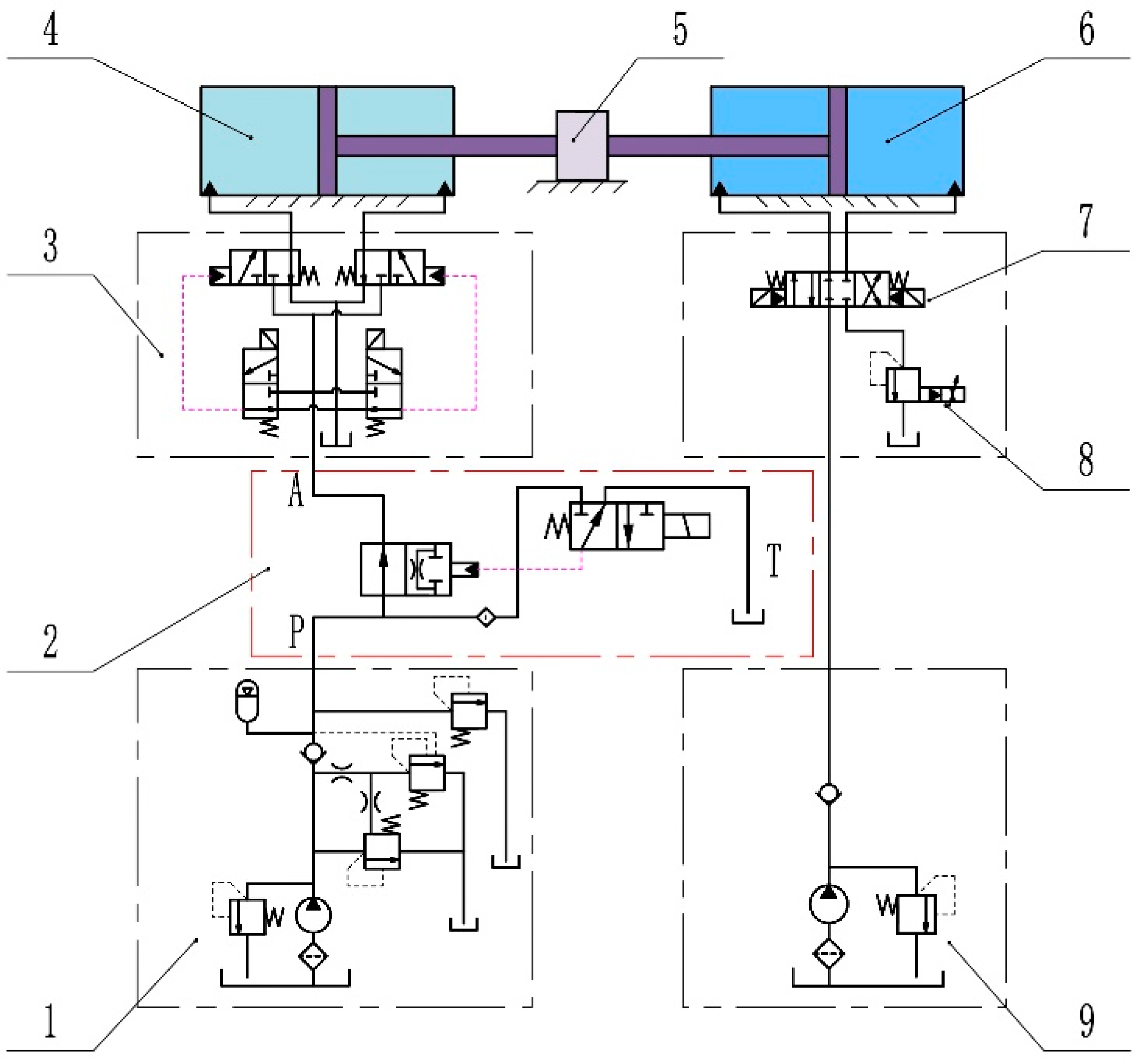
The double-valve series system studied in this paper is shown in Figure 1.

Figure 1.
Schematic of double-valve series pushing system. 1: Emulsion pump station, 2: two-speed buffer valve, 3: electro-hydraulic directional valve, 4: push hydraulic cylinder, 5: the link block, 6: the load cylinder, 7: the reversing valve; 8: the relief valve, 9: the loading pump.
The double-valve series push system uses the emulsion pump as the hydraulic source, and supplies the liquid to the push circuit after the safety valve and the unloading valve. The push process is controlled by the double-speed buffer valve 2 and the electro-hydraulic directional valve 3. The loading circuit is replenished by the loading pump, and the relief valve is adjusted to simulate the change in different loads. Compared with the pushing system of fully mechanized mining support, the double-valve series pushing system adds a double-speed buffer valve in front of the electro-hydraulic directional valve to adjust the liquid supply flow, and the direction and on-off of the liquid supply flow are controlled by the electro-hydraulic directional valve; when the electromagnetic pilot valve of the two-speed buffer valve is not powered, the emulsion is fed through the main channel of the two-speed buffer valve; when the electromagnetic pilot valve is energized, the hydraulic control main spool is closed, forming a conical seal with the valve seat, and the throttling flow channel opened on the spool is used to split the liquid supply, resulting in pressure difference and throttling, reducing the amplitude of the sudden change in pressure and flow, thereby slowing down the hydraulic impact.
Usually, in the process of hydraulic support pushing, the amplitude of the sudden change in the pressure of the system in the start-stop stage is the largest. In view of this phenomenon, a pushing scheme of two-speed valve and directional valve series control is proposed. In the initial stage, the pilot of the double-speed buffer valve is energized, the main spool is displaced, and switched to the throttling gear. Then, the electro-hydraulic directional valve acts, the small flow liquid is passed, and the hydraulic cylinder starts at low speed. When the pressure is stable, in order to ensure the pushing efficiency, the two-speed valve is powered off, the main spool is reset, switched to the flow gear, and the large flow is supplied to ensure the rapid pushing of the hydraulic cylinder. In the stop stage, the double-speed valve is energized, the throttling liquid is supplied, and the hydraulic cylinder is positioned at low speed. On the one hand, the double-valve series scheme can adopt a small flow and low speed to improve the positioning accuracy. On the other hand, the step-by-step pressure reduction reduces the impact caused by the excessive pressure drop at the moment of on-off of the directional valve.
2. Structure and System Analysis of Double-Speed Buffer Valve
2.1. The Design of Two-Speed Buffer Valve
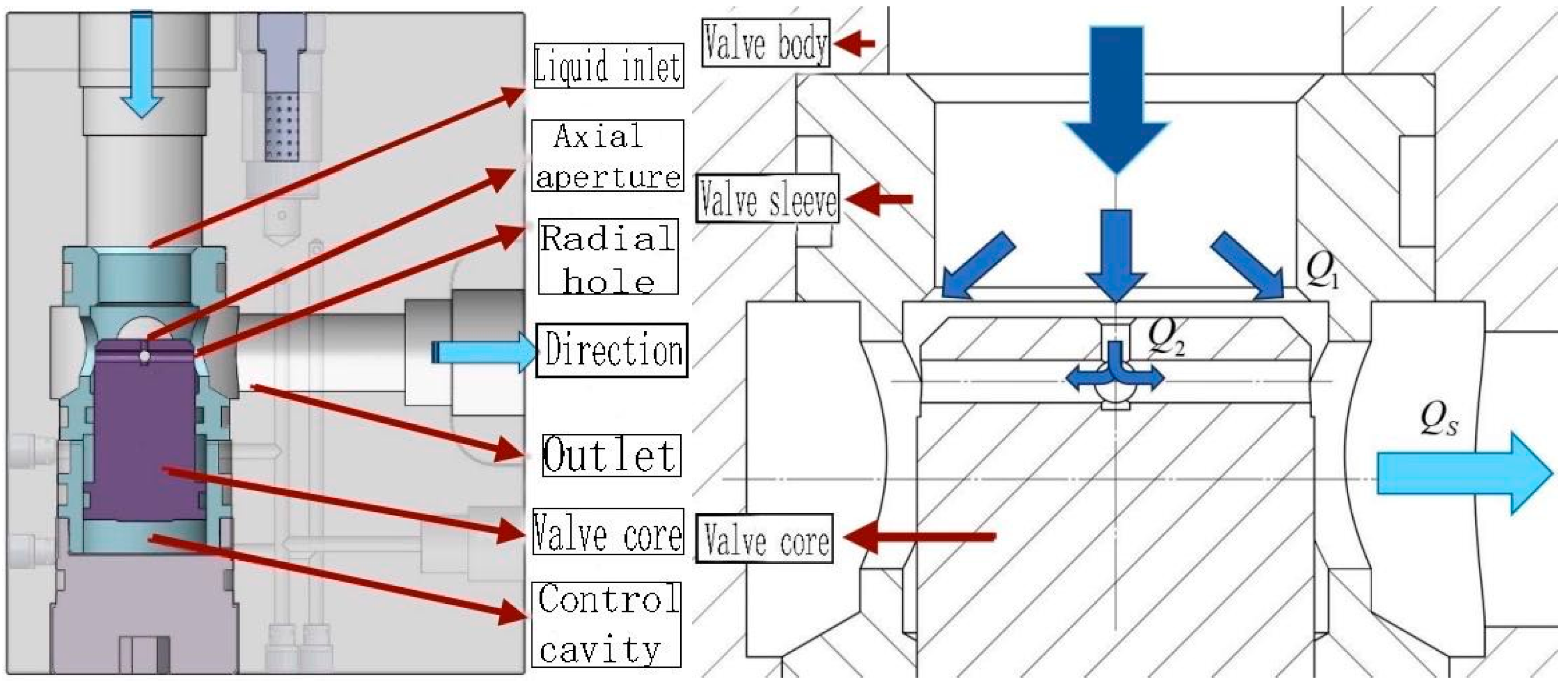
The scheme optimizes the valve core of the shut-off valve and opens radial holes and axial holes. Compared with the multi-channel switch speed control valve, the optimization scheme adopts a non-on-off structure, which always connects the liquid supply port and the liquid outlet port. The structure is simple and suitable for bad underground working conditions, and can avoid the sudden change in pressure and flow caused by the complete opening and closing of the flow channel. The structure of the two-speed buffer valve is shown in Figure 2.

Figure 2.
Structure of two-speed buffer valve.
When the double-speed buffer valve is used for liquid, a large amount of emulsion enters from the inlet into the main channel through the main valve core to the outlet. A small amount of emulsion enters the electromagnetic pilot valve through the fine flow channel and filter set by the side, and the hydraulic control circuit is controlled by the electrical signal. When the solenoid valve is energized, the hydraulic control flow channel is opened, the hydraulic control cavity at the lower end of the valve core is filled with liquid, the pressure difference formed by the area difference between the upper and lower ends of the valve core pushes the valve core upward, and the inlet port is closed. The axial and radial orifices opened at the upper and side ends of the valve core connect the inlet and outlet flow channels, and throttling is performed to supply liquid with small flow. When the solenoid valve is powered off, the pilot valve is connected with the outlet, and the liquid in the lower chamber of the valve core is discharged. The newly formed pressure difference between the upper and lower ends resets the valve core, and the main flow channel of the liquid supply is directly connected with the main flow channel of the liquid outlet for large-flow liquid supply. In the whole process of opening and closing, the throttling flow channel is always connected, which is beneficial to reduce the sudden change in pressure flow.
2.2. Analysis of Fully Mechanized Mining Support Moving System
Firstly, the mathematical model of the pushing system is established and the theoretical analysis is carried out. The pushing process is divided into two processes: unsteady opening and steady pushing. The pressure flow characteristics are studied to provide a theoretical basis for subsequent simulation and experiment. The mathematical model is established according to the push loop in Figure 1. Ignoring the system leakage, the volume from the double-speed buffer valve to the rodless cavity of the hydraulic cylinder is regarded as a dynamic closed cavity. When the rodless cavity is the inlet cavity, the dynamic equation of pressure and flow in this part is as follows:
: Inlet chamber pressure; : inlet flow rate; : effective bulk modulus of cavity; : initial volume of liquid inlet chamber; : effective area of liquid inlet cavity; : piston rod displacement.
The load force balance equation of the system is as follows:
When the static friction changes into the dynamic friction, the friction is positively correlated with the velocity υ. There is a linear positive correlation between liquid resistance and velocity υ. If , ,
: external load, linear scaling factor, : effective area of liquid outlet cavity.
According to the two-speed buffer valve, the static flow continuity equation is established as follows:
, : Valve port flow coefficient, : Pressure difference of valve port, , the equivalent liquid resistance is as follows:
: Axial throttling channel diameter, : diameter of radial throttling flow channel, : oil density, : dynamic viscosity, : radial hole length.
In the hydraulic system, before the electro-hydraulic directional valve (Y type) is opened, the rodless cavity and the rod cavity are connected to the oil tank, and the emulsion flow rate is zero. At the moment of opening the reversing valve, the hydraulic cylinder did not respond immediately under the action of load and static friction force, and the inlet chamber was closed and boosted. The pressure flow Equation (1) of the dynamic closed cavity shows that (the velocity of the piston rod) and (displacement) is zero. (the pressure rise rate in the cavity) is positively correlated with (inlet flow rate). Once the velocity and volume begin to increase, (the pressure change rate) decreases, but it is still related to (the inlet flow rate) until the pressure peak is reached.
The above process increases with the pressure of the inlet chamber until it is sufficient to overcome the static friction, load, and back pressure. Due to the pressure response lag, overshoot occurs. At this time, the static friction force decreases with the piston starting to move into the dynamic friction force, resulting in force imbalance. Therefore, as shown in Equation (2), the piston is accelerated and the is reduced until a new force balance is reached; during this process, the pressure will change sharply until it reaches a steady state. After the steady state, (the acceleration) of Equation (3) is basically zero. In addition to the constant parameters of the hydraulic cylinder and the given external load force, (the pressure) is related to the speed of the piston rod; that is, it is positively correlated with the inlet flow rate.
In summary, the start-up and operation pressure characteristics of the system can be improved by adjusting the flow rate. In Equation (4), when the two-speed buffer valve is opened, the hydraulic pressure on the spool acts on the valve seat, and (the flow rate at the valve edge) is reduced to zero. The flow rate through the throttling flow channel on the spool is , and the equivalent liquid resistance is . Combining Equations (4) and (5), it can be seen that reducing the diameter of the axial hole or the diameter of the radial hole alone will increase the equivalent liquid resistance of the throttling flow channel and reduce (the flow rate through the valve). When the two-speed valve is closed, the spool is reset, and (the flow through the valve) includes and , which no longer throttles with the increase in , equivalent to the flow directly through the pipe diameter. The above analysis shows the causes of hydraulic shock and its improvement methods. Because the two-speed buffer valve is opened first in the control scheme, and then the electro-hydraulic directional valve is opened after switching to a small flow rate, the small flow rate liquid supply reduces the maximum pressure drop during the start-stop process, which plays a buffering role and makes the operation process more stable.
3. Simulation of Flow Field Characteristics
3.1. Establishment of Flow Field Model in Valve
In order to study the internal flow field characteristics and applicable conditions of the two-speed buffer valve, a simulation study was carried out. According to the structure of the two-speed buffer valve shown in Figure 2, a three-dimensional geometric model of the two-speed buffer valve was built in Solidworks software (Solidworks 2021). The geometric model was preprocessed and meshed by Ansys/Fluent Meshing. The geometric model and the obtained flow field model are shown in Figure 3.
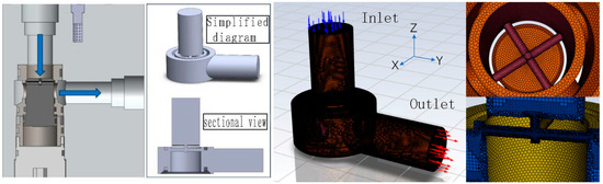
Figure 3.
Geometric model and flow field model after mesh division.
After the watershed is modeled and meshed in the software, the model parameters need to be set, such as the properties of the relevant fluid and the simplification of non-critical calculations. In addition, due to the complex working conditions of the double-speed buffer valve, only the maximum pressure difference is used to simulate the harsh working conditions, and the two-phase mixture of water and steam is regarded as an ideal fluid medium, ignoring the numerical changes of its physical properties such as density due to the environment. The parameter settings are shown in Table 1.

Table 1.
Related settings of the main runner simulation model.
When the parameters are set up, in order to ensure the credibility of the simulation results, it is necessary to achieve a certain convergence condition. After referring to the relevant literature, the model is judged in the following ways: the residual error of the discrete equation is set to , and if it is less than this value, the convergence condition is reached by default; the amount of output report of the system does not change with the increase in iteration steps or non-periodic oscillation, and the import and export substances are balanced.
3.2. The Simulation and Analysis
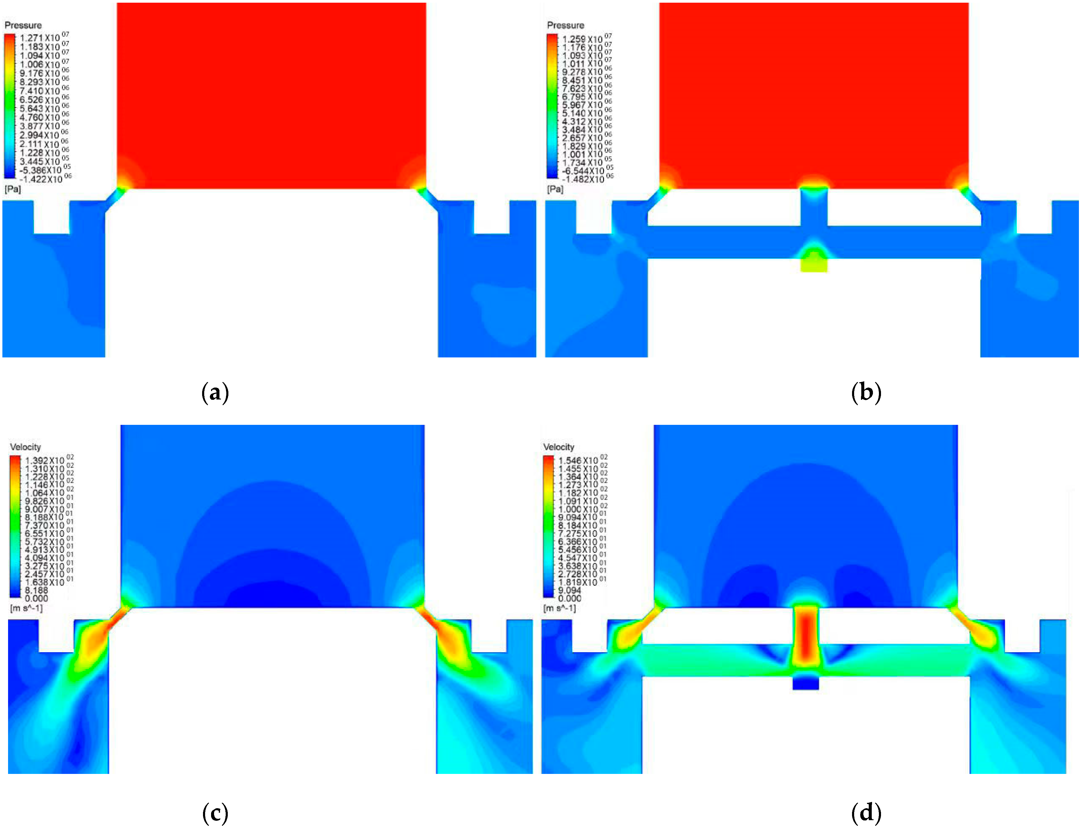
Relevant research shows that when the opening of the valve port is small, the medium will pass through the small valve edge flow channel at high speed, which is easy to cause excessive pressure difference near the valve port and lead to serious cavitation. Therefore, this paper compares the main valve structure of the general multi-channel speed control valve with the two-speed buffer valve with the throttling flow channel in this paper, and studies the improvement effect of the additional orifice of the two-speed valve on the flow field distribution under the displacement of 1 mm spool. The pressure flow distribution is analyzed. The Y-Z cross-section flow field calculation simulation results of the two types of valves are enlarged as shown in Figure 4.

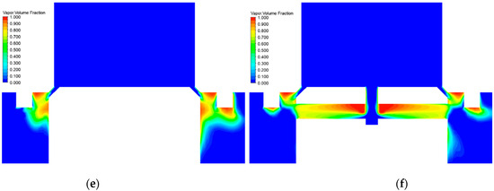
Figure 4.
Pressure-flow curve for opening two-speed valve. (a) Pressure cloud diagram of the structure without throttling runner; (b) pressure cloud diagram of the structure with throttling runner; (c) velocity cloud diagram of the structure without throttling runner; (d) velocity cloud diagram of the structure with throttling runner; (e) gas phase volume fraction cloud diagram of the structure without throttling runner; (f) gas phase volume fraction cloud diagram of the structure with throttling runner.
It can be seen from the pressure cloud diagram of the simulation results that the pressure changes obviously at the valve port of the two structures. When the medium flows through this position, the gradient of the pressure change is large, and the pressure value drops sharply. When the spool displacement is 1 m, it can be observed that there is a large low-pressure area at the top corner of the valve sleeve and the upper end of the valve core side wall without the orifice structure. The high-pressure medium has just flowed through the area with a large pressure gradient at the valve port, and then it is easy to produce cavitation after passing through these low-pressure areas. Under the same working conditions, the drainage effect of the throttling flow channel of the double-speed buffer valve has a certain pressure compensation effect on the valve port, which significantly reduces the area of the low-pressure area of the valve core side wall. The low-pressure area at the top of the valve sleeve decreases and moves to the right side, which is conducive to suppressing the occurrence of cavitation.
It can be seen from the velocity cloud diagram that the medium flows at a low speed before the entrance. When passing through the valve port, the flow velocity rises sharply with the decrease in the flow area, showing a jet state. At the corner of the cone surface of the valve core, the velocity gradient begins to increase and the velocity gradually decreases. When the displacement is small, the medium flow rate through the narrow mouth of the valve edge sealing surface is large, but the flow area is small, which has little effect on the pressure in front of the valve port, and the low-speed area in the back of the valve port is more obvious. However, after adding the orifice, in addition to the narrow orifice of the valve edge, the medium is also connected to the basin behind the valve port at a higher flow rate from the throttling flow channel, and the low-speed zone behind the valve port is widely reduced. In the above process, the additional throttling flow channel plays a role in connecting the surrounding media of the valve core, so that the overall pressure and velocity distribution of the flow field is more balanced. The overall flow rate will decrease rapidly with the increase in the flow area before and after the radial hole, and a large deceleration effect will be achieved.
By comparing the two structures, it can be observed that after adding the orifice, the medium flowing out from the orifice is affected by the high-speed jet at the valve port, and the streamline is shifted upward and converged with the tail of the small velocity gradient of the high-speed jet, so that the original high-speed jet tail is also shifted upward and the area of the high-speed area is weakened, and the medium flow direction is closer to the valve sleeve outlet wall; at the same time, it can be observed that after adding the orifice, the above effect makes the low-speed zone below the flow channel have a tendency to move up, and the gradient is more gentle. According to the above phenomenon, it can be seen that the addition of the orifice reduces the sudden change in the corner of the valve core sealing surface and its side velocity to varying degrees, which is conducive to suppressing the occurrence of cavitation. Through the low-pressure zone and the place where the pressure and velocity change gradient are large, it can be roughly inferred that the cavitation occurs at the valve sleeve port, the valve core seal corner and its side wall. In order to view the cavitation phenomenon more intuitively, it is also necessary to analyze it according to the gas phase volume fraction cloud map.
It can be seen from the gas volume fraction cloud diagram that when the displacement is small, the gas volume fraction in the low-pressure area of the high-speed jet and the valve sleeve wall and the low-pressure area of the valve sleeve port is large. For the non-throttle orifice structure, under the influence of the high-speed jet, the low-speed fluid at the side end of the valve core forms a large velocity gradient with it. The viscous shear force causes the fluid near the side wall to move away from the wall to form a low-pressure area, and the cavitation phenomenon is serious. After adding the orifice, the medium with high orifice emission velocity makes up for the low-pressure effect caused by the high-speed jet to a certain extent. The low-speed zone and low-pressure zone of the valve core side wall are improved to a certain extent, and the gas volume fraction at the side wall is significantly reduced. In addition, because the throttling medium has a certain interference effect on the tail of the high-speed jet when the opening of the valve port is small, the gradient of the tail velocity change is attenuated and the position of the tail velocity change is moved up as a whole, resulting in the improvement of the low-speed zone with a large gradient near the valve sleeve wall. In summary, by comparing the gas phase volume fraction cloud images of the two structures, it can be concluded that in the small opening state where cavitation is easy to occur, the additional throttle hole of the double-speed buffer valve can offset the incident streamline and increase the energy consumption of the medium flow, which has a significant effect on improving the cavitation phenomenon of the valve sleeve and the side wall of the valve core.
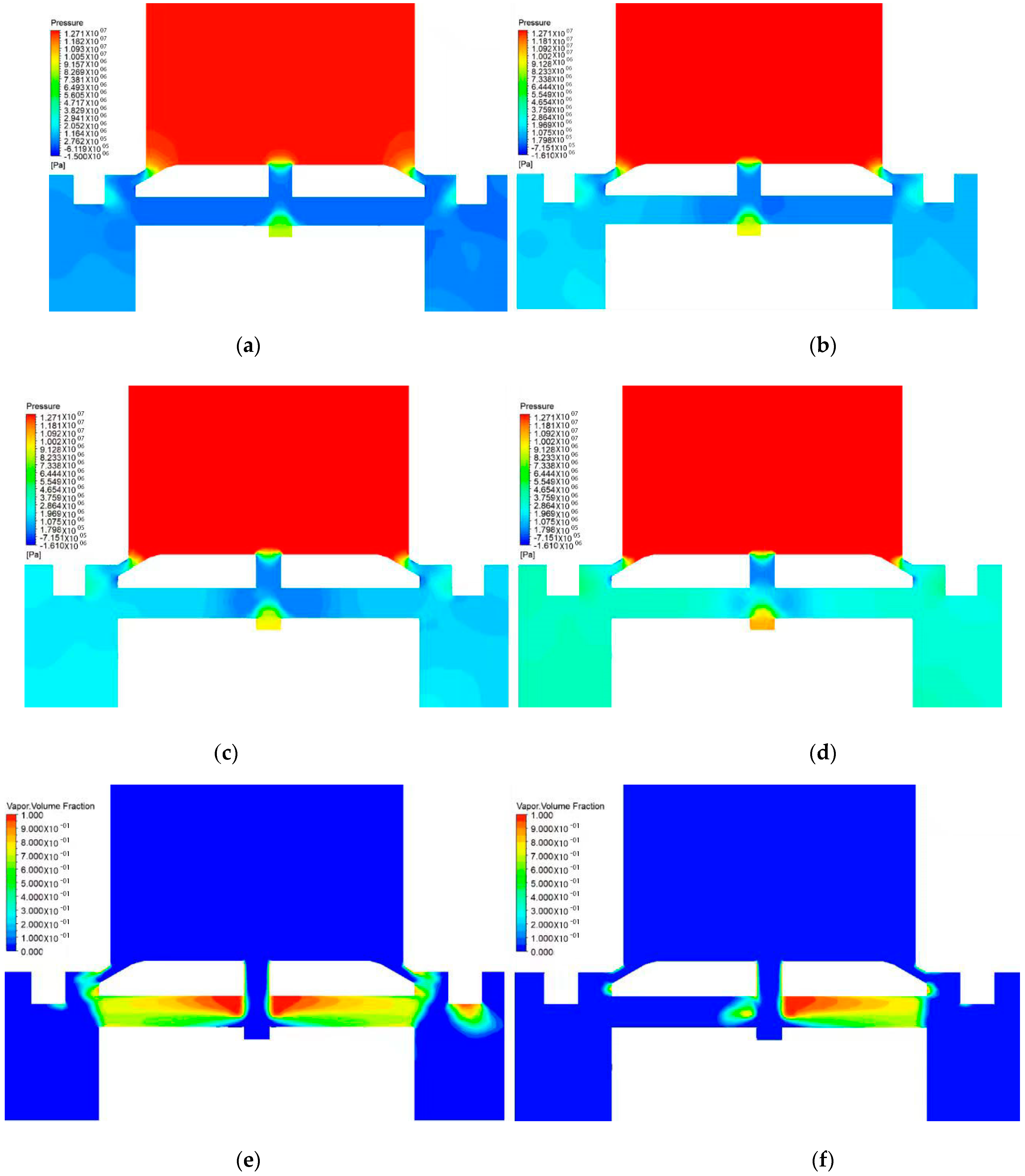
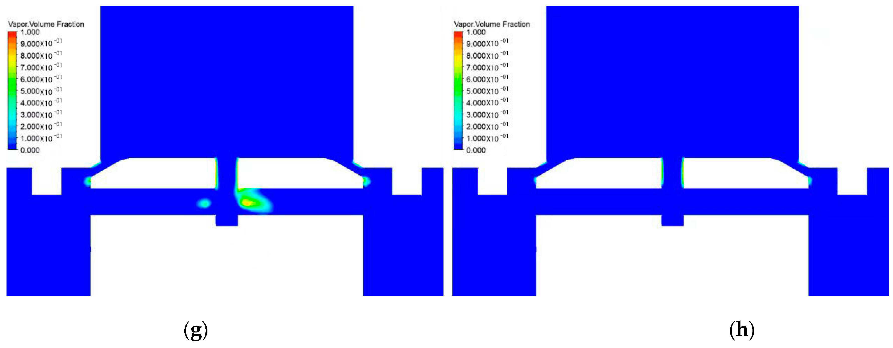
In the above research, the flow field distribution around the valve port, valve core, and valve sleeve has been greatly improved after the introduction of the throttling flow channel. However, due to the rapid change in the flow area of the throttling flow channel itself, the low-pressure area of the internal corner is difficult to reduce. However, according to the research process of the above opening degree, it is known that when the displacement of the valve core increases, the back pressure of the outlet of the throttling flow channel increases, and the cavitation phenomenon will gradually reduce. Therefore, the cavitation phenomenon in the valve basin under different working conditions is studied. After many simulations, it is found that the cavitation phenomenon gradually weakens with the increase in outlet pressure. In order to facilitate comparative analysis, different gradient pressure values are selected. According to the same maximum pressure difference condition, only the outlet pressure is 0 MPa, 1 MPa, 1.5 MPa, 3 MPa. The simulation results of the flow field are shown in Figure 5.


Figure 5.
Flow field distribution diagram of different working conditions. (a) Pressure cloud diagram at 0 MPa outlet pressure; (b) pressure cloud diagram at 1 MPa outlet pressure; (c) pressure cloud diagram at 1.5 MPa outlet pressure; (d) pressure cloud diagram at 3 MPa outlet pressure; (e) gas phase cloud diagram at 0 MPa outlet pressure; (f) gas phase cloud diagram at 1 MPa outlet pressure; (g) gas phase cloud diagram at 1.5 MPa outlet pressure; (h) gas phase cloud diagram at 3 MPa outlet pressure.
According to the flow field distribution cloud map, when the outlet pressure is set from 0 MPa to 1 MPa, the increase in the outlet back pressure leads to a general increase in the pressure behind the valve port, which can not only reduce the low-pressure area near the valve sleeve. When the pressure increases to 1.5 MPa, there is basically no negative pressure area in the throttling flow channel. When it rises to 3 MPa, the pressure difference between the inside and outside of the throttling flow channel is smaller, and the overall pressure distribution is more uniform. Observing the process of increasing the outlet pressure, due to the increase in the back pressure, the velocity in the radial flow channel of the closed end of the main flow channel decreases. With the increase in the pressure behind the valve, the velocity in the radial flow channel of the outlet end also begins to decrease, and finally, the medium velocity in the throttling flow channel is uniform and low. Combined with the gas volume fraction cloud diagram, it can be observed that with the increase in back pressure, the weakening trend of the cavitation phenomenon is consistent with the change trend of the pressure and velocity gradient. The cavitation phenomenon of the radial hole at the closed end of the main channel dissipates first. When the back pressure is large enough, the cavitation phenomenon in the radial hole at the outlet of the main channel and even in the whole throttling channel can be reduced. Therefore, according to the above research, in order to suppress the cavitation phenomenon, avoid destroying the structure of the two-speed buffer valve, and ensure its stable working performance, the two-speed buffer valve should work in an environment with an outlet pressure of at least 1.5 MPa. According to the relevant tests, in the working process of the support pushing system, even if it is lower than the normal working pressure and the input flow rate is small, the pressure in front of the (Y-type) electro-hydraulic directional valve can be guaranteed to meet the above requirements; that is, it is higher than 15 MPa before it is not opened, and it is always higher than 5 MPa after it is opened, which ensures that there is sufficient back pressure behind the two-speed buffer valve. Therefore, through the above analysis, the double-speed buffer valve is suitable for the working conditions of the downhole hydraulic support push system.
4. Experimental Study
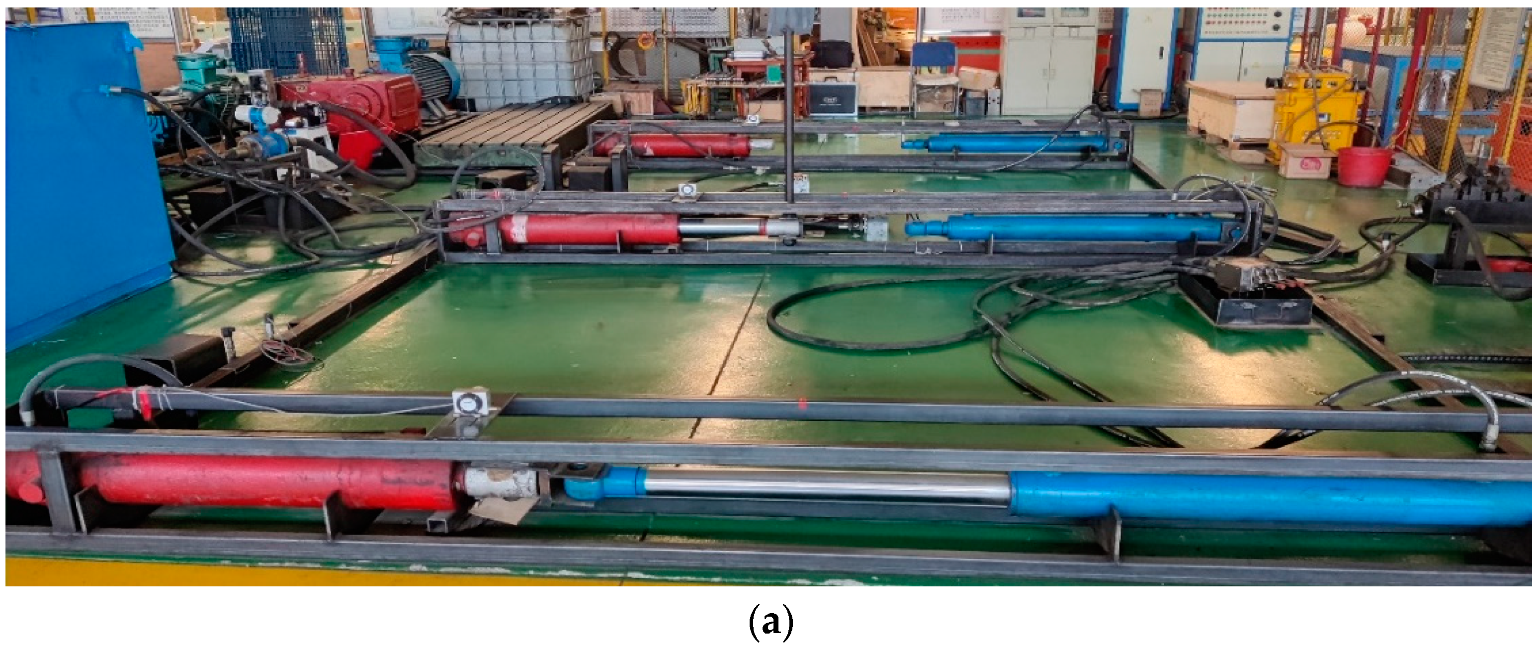
In order to test the improvement effect of the two-speed buffer valve on the characteristics of the hydraulic support pushing system and study the influence of different system inputs on the pushing characteristics, a simulation test bench of the hydraulic support pushing system was built in the engineering laboratory, as shown in Figure 6.


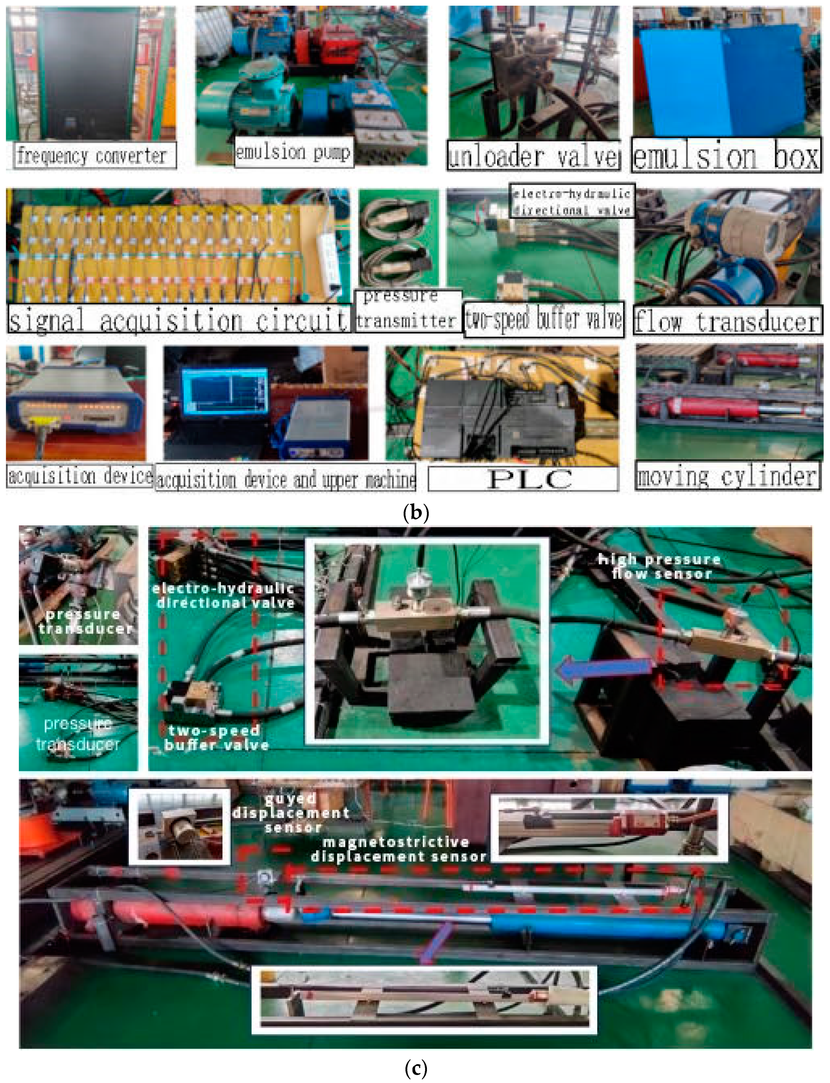
Figure 6.
Simulation experimental platform of pushing system. (a) The simulation test platform of the stent passage motion; (b) key components and equipment of the test bench; (c) installation position of the pressure, flow rate, and displacement speed sensor of the test system.
In the test system, the pumping station is used as the hydraulic source to provide power for the movement of the hydraulic cylinder, and the input flow of the system is adjusted by the frequency converter. The test system relies on the loading oil circuit to simulate the force of the push system, and the hydraulic cylinder motion is controlled by the double-speed buffer valve and the electro-hydraulic directional valve. By changing the input of the system to simulate different working conditions, the push process of the system under the corresponding conditions is studied. The acquisition system is installed on the test bench to collect and process the data. The pressure transmitter (MIK-P300) is installed before and after the control valve. The high-pressure flow sensor (CT turbine flow sensor) is installed on the liquid supply pipeline. The magnetostrictive linear displacement sensor is installed on the hydraulic cylinder. The state variables of the system are collected by the above sensors. The collected analog signal is transmitted to the host computer through the acquisition card for data processing and storage. Finally, the voltage of the PLC output terminal controls the on-off of the two valves, thereby controlling the movement of the pushing system. The relevant acquisition test system is shown in Figure 6.
4.1. The Pressure Characteristics
On the push system simulation test bench, in order to verify the impact mitigation effect of the two-speed buffer valve, when the input pressure of the system is 23 MPa, the hydraulic cylinder with 110 mm cylinder diameter is used to move the frame. The pressure test curve of the rod cavity of the hydraulic cylinder during the movement is shown in Figure 7.

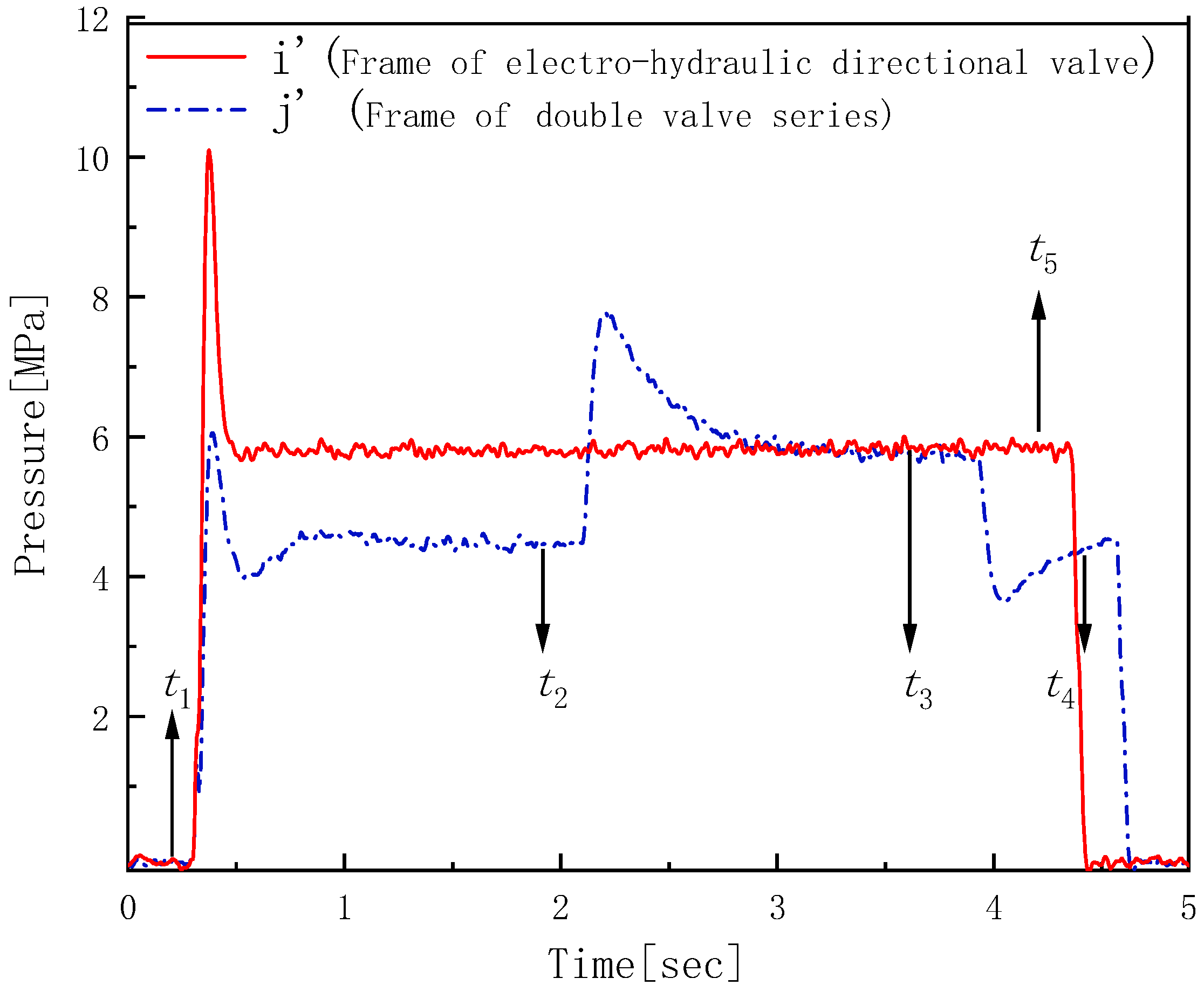
Figure 7.
The pressure test curve under two kinds of pulling processes.
In the shift curve of the electro-hydraulic directional valve (), the directional valve is opened at , and the directional valve is closed at ; in the process of the double-valve series moving frame (), it is divided into three stages: the two-speed buffer valve in 0 is opened, the electro-hydraulic directional valve is opened at , and the system starts at low speed with small flow; in ,the double-speed valve is closed, the large flow is supplied, and the system moves quickly; the double-speed buffer valve is opened at ; the small flow fluid is supplied in , and the system stops at low speed.
It can be seen from the measured pressure curve of the above figure that the steady-state operating pressure of the two moving modes is roughly the same at about 3 s. However, during the short start-up and final stop process after t1, the opening and closing double-speed buffer valves complete the graded pressure change, and the first pressure sudden change is converted into two small pressure changes, which significantly reduces the amplitude of the sudden change in the maximum pressure during the whole movement process, and its maximum overshoot is reduced from 76 to 36. Corresponding to the part with the largest pressure change in the curve, after the dual-speed buffer valve is enabled, the peak pressure decreases from 10.1 MPa to nearly 40 to 6.1 MPa, and the response time is extended by about 15 ms, so that the pressure change rate is greatly reduced, which verifies the previous theoretical analysis and the effectiveness of the dual-valve series shift scheme.
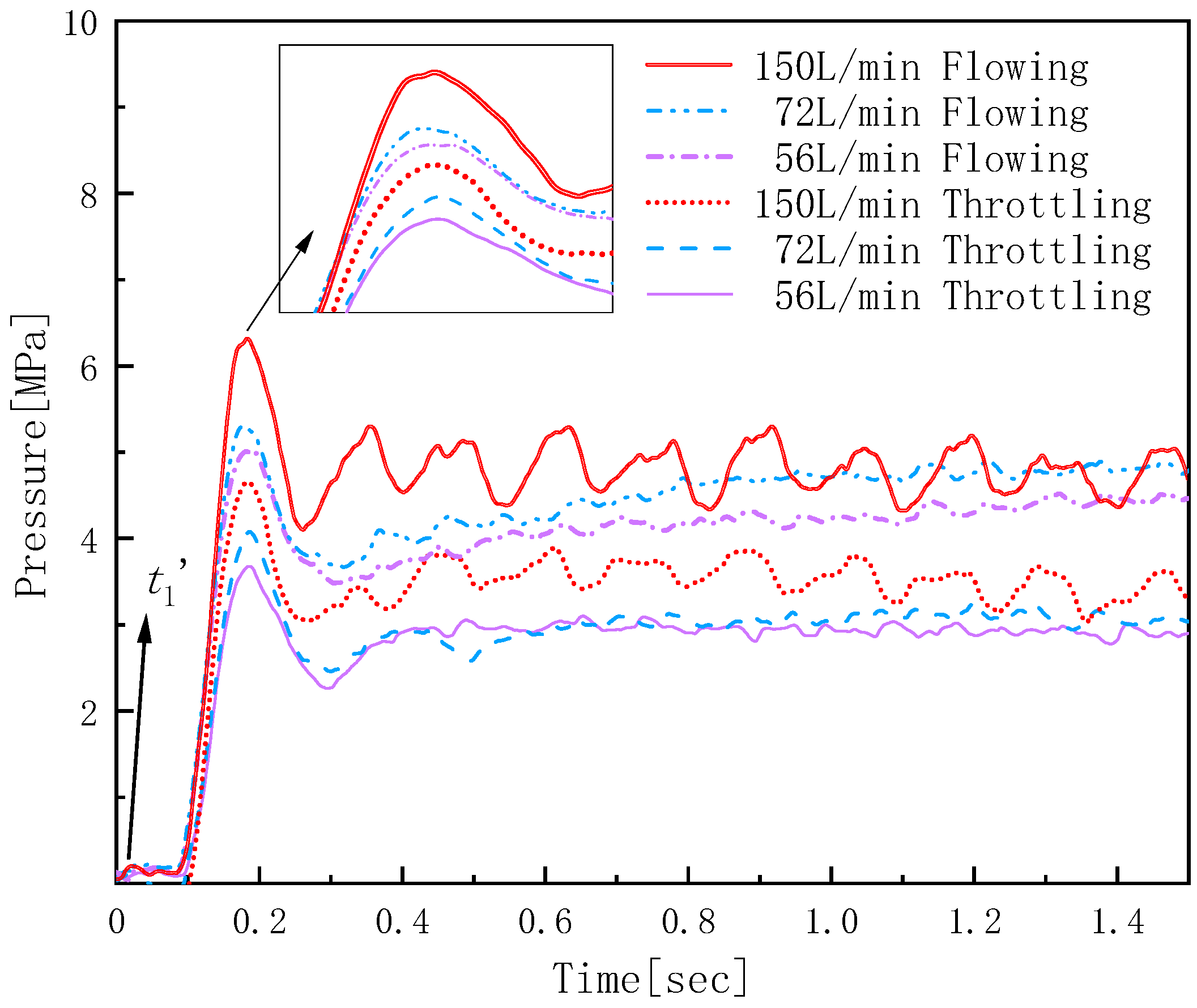
In order to verify the performance of the double-speed buffer valve under different working conditions and its influence on the system characteristics after the control valve, multiple sets of tests were carried out with a cylinder diameter of 160 mm and a rod diameter of 105 mm under the system input pressure of 23 MPa. It can be seen from the relevant research that the maximum part of the pressure impact during the moving process occurs in the start-up stage. In view of this phenomenon, multiple sets of tests under different input flow rates were carried out. The pressure response curve after the control valve is obtained by using the two-speed valve throttling and flow gear, respectively, as shown in Figure 8.
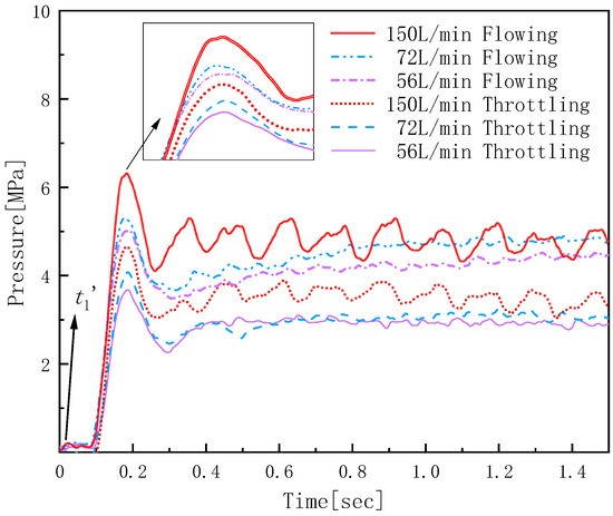
Figure 8.
Downstream pressure test curve at different system flow rates.
Through the analysis of the above curve, it can be seen that in the short time after the valve is opened, the change rate of pressure behind the valve is very large. After experiencing pressure rise and response change, it reaches a relatively stable operating state. Then, although the pressure fluctuates continuously, the overall trend is no longer changing. By comparing the pressure test curves of the two-speed valve under throttling and through-flow gears, it can be seen that under the same system input pressure, the start-up impact of the two liquid supply modes of the two-speed valve increases with the increase in the input flow rate. At the same time, the steady-state pressure value also increases as the speed and liquid resistance increase. This part of the test phenomenon is consistent with the previous theoretical analysis results.
In addition, by comparing the test data under the two liquid supply modes, it can be observed that under various input flow rates, the hydraulic impact phenomenon during the start-up process is slowed down after the throttling gear is turned on, and the pressure fluctuation amplitude is also reduced. Taking the test data under 56 L/min and 72 L/min flow rates as an example, when the increment of the system input flow is small, the change range of the test curve after the throttling gear is enabled is small, and the steady-state pressure trend and value are relatively close. The throttling liquid supply method is beneficial to reduce the influence of flow fluctuation on the pressure behind the valve and improve the anti-interference of the pressure behind the valve on the input flow change.
4.2. The Characteristics of Speed and Flow
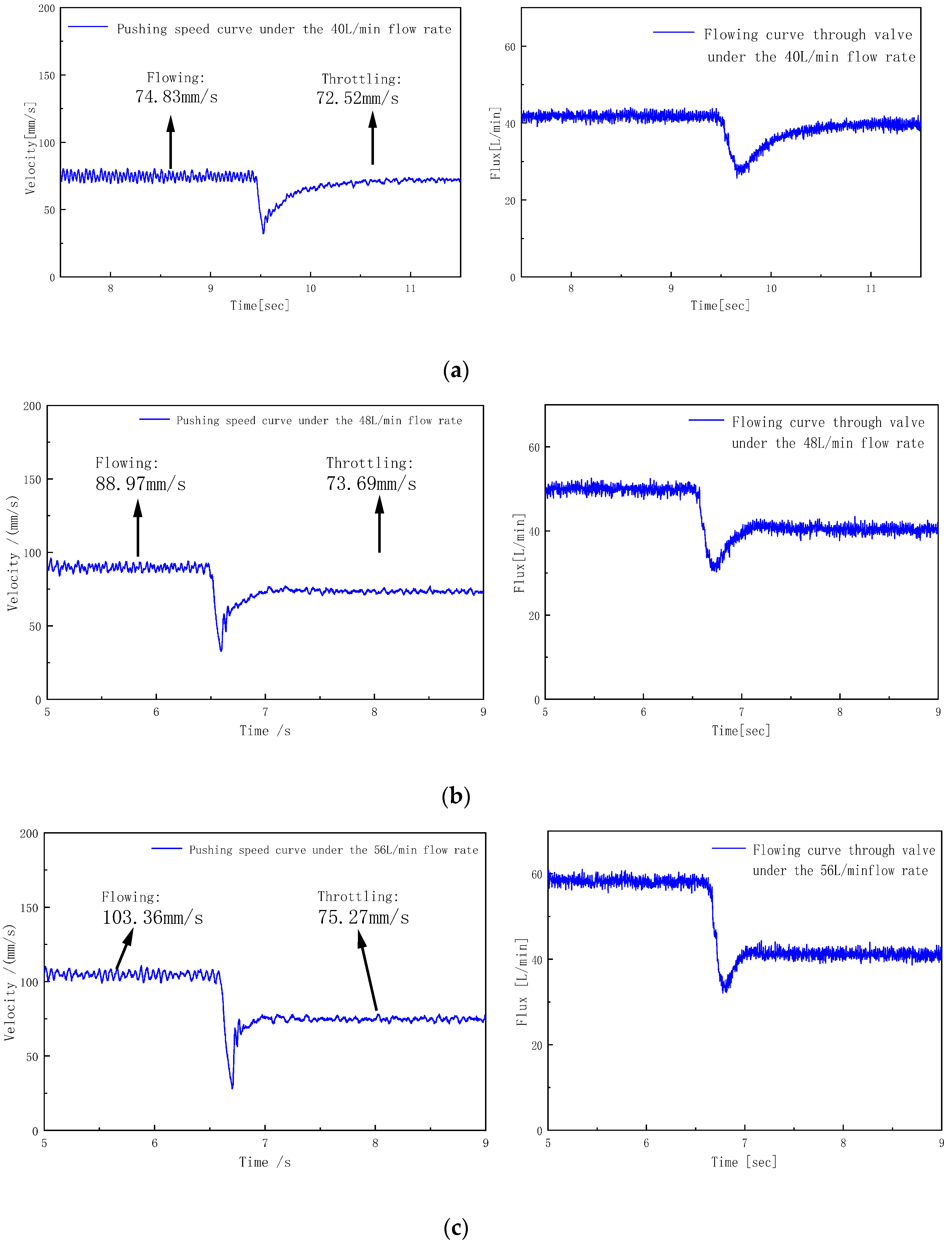
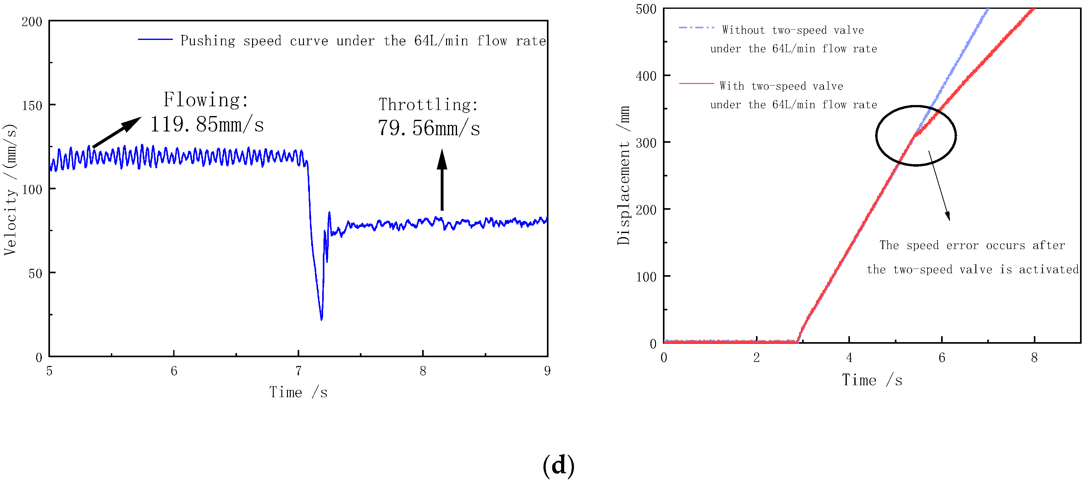
In order to study the influence of the two-speed buffer valve on the speed and flow characteristics of the system, the deceleration performance of the two-speed buffer valve was first tested. Under the system input flow of 40, 48, 56, and 64 L/min, the hydraulic cylinder with a cylinder diameter of 110 mm was used to carry out the push test. During the push process, the two-speed buffer valve throttling and flow gear were switched, respectively, to measure the following test curves (Figure 9).


Figure 9.
Test curve at different input flow rates. (a) Velocity flow test curve at 40 L/min system input flow; (b) velocity flow test curve at 48 L/min system input flow; (c) velocity flow test curve at 56 L/min system input flow; (d) velocity displacement test curve at 64 L/min system input flow.
From the above curves, it can be seen that when the system input flow increases, the flow and throttling gear speed before and after the dual-speed buffer valve is enabled increases. When the input flow rate changes from 40 L/min to 64 L/min, the increase percentage of the velocity under the through-flow liquid supply is 60.16%, while the increase ratio of the throttling gear is 9.71%. The change in the through-flow gear speed is approximately proportional to the change in the system input flow rate, while the change in the throttling gear speed is significantly reduced, which is beneficial to enhance the anti-interference of the system speed to the change in the input flow rate.
Comparing the influence of the two liquid supply methods on the speed under different flow rates, it can be seen that the throttling gear can play a certain speed reduction effect. When the input flow rate of the system is small at about 40 L/min, the speed of the through-flow gear system itself is slow. The speed reduction effect of the two-speed buffer valve is not obvious, and the speed difference between the two is about 15 mm/s. When the input flow rate continues to increase, due to the throttling characteristics of the two-speed valve, the speed difference between the two methods is increasing. When the speed difference increases to about 40 mm/s, the throttling effect is obvious, and it becomes more and more significant with the increase in the input flow rate, and the speed reduction effect of the system is obvious. From the displacement curve under the input flow of the 64 L/min system, it can also be observed that the slope of the curve changes significantly due to the speed difference after the dual-speed valve is enabled, and the speed reduction effect is obvious. At the same time, it can be observed that the fluctuation amplitude of the velocity is also significantly reduced after the two-speed buffer valve is turned on the throttling gear.
In the above diagram, it can also be seen that the change trend of the flow rate of the valve is highly similar to the change trend of the speed from the shape. The flow rate and the speed of the valve are reduced to a lower state value after the command switching of the two-speed buffer valve. It can be observed that with the increase in the input flow, the time of the change process is shortened, the system can reach a relatively stable state faster, and the speed and flow rate no longer have a large change trend. Therefore, sufficient input flow can make the system respond faster. Therefore, the above characteristics are beneficial to improve the motion characteristics of the system in the positioning stage, and make the moving cylinder easier to control in the stop stage of the system.
4.3. The Location Characteristic
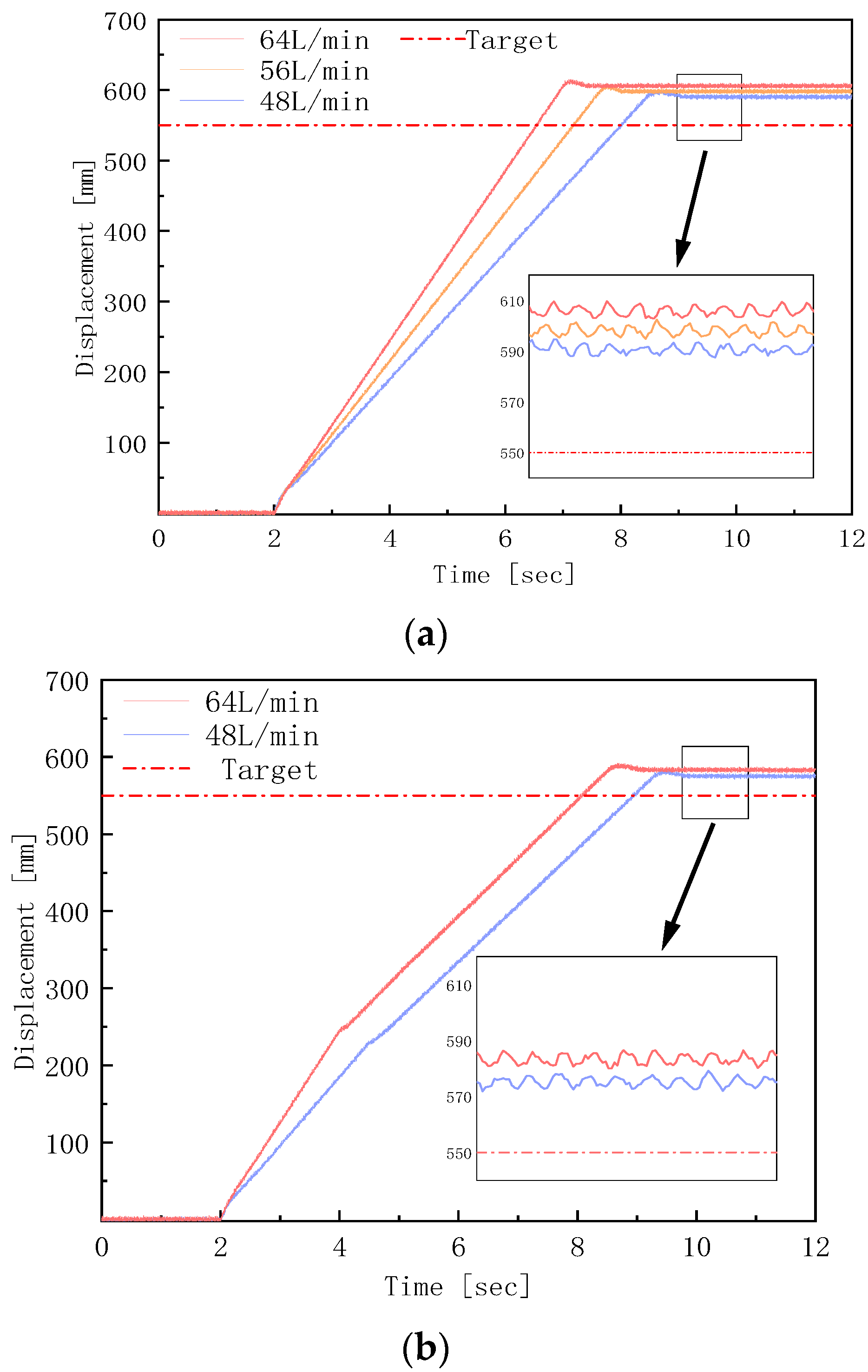
The above test process studied the speed and flow characteristics of the double-valve series push system, and then studied the improvement effect of the double-valve series push system. At present, most of the mining areas realize the final positioning by the logical positioning control and manual cooperation of the stroke sensor in the hydraulic cylinder. The following are the electro-hydraulic directional valve positioning test and the double-valve series positioning test based on the logical positioning control method. Taking 550 mm as the final positioning target position, multiple sets of tests are carried out under the system input flow of 48, 56, and 64 L/min, respectively. The test curve and its positioning results are shown in Figure 10 and Table 2.

Figure 10.
Displacement test curves of positioning process with different control methods. (a) Positioning test of electro-hydraulic directional valve based on logical positioning; (b) positioning test of two-valve series based on logical positioning.
Table 2.
Positioning results of different control methods.
From the displacement curve of the control element in Figure 10b, it can be observed that after the dual-speed buffer valve is enabled, the positioning error at the minimum 48 L/min flow rate is reduced by 14.85 mm, and the positioning error at the maximum 64 L/min flow rate is reduced by 22.88 mm. The final positioning error shows a downward trend. In addition, the error between the maximum and minimum flow rates of 64 L/min and 48 L/min decreased from 15.46 to 7.43 with the change in flow rate. Therefore, the speed and flow characteristics of the above two-speed buffer valve are beneficial to improve the positioning effect of the system. Firstly, it reduces the running speed of the system and indirectly reduces the influence of action delay, thus reducing the overall error of positioning. Secondly, due to the smaller change amplitude of the system speed after the two-speed valve is enabled, the degree of change in the positioning error due to the flow is reduced.
According to the previous research, the buffering and positioning effect of the double-valve series pushing system is basically in line with expectations. Its pressure and flow characteristics improve the motion characteristics of the system. The double-speed buffer valve reduces the positioning error of the system and weakens the influence of flow changes on the pushing process, which verifies the effectiveness of the double-valve series positioning control method.
5. The Conclusions
Aiming at the problem of a large hydraulic impact when the on-off switch valve of the pushing system in the fully mechanized mining face is started, the theoretical analysis of the pushing system is carried out, and a two-speed buffer valve structure for the underground pushing system is designed. The flow field characteristics are studied by simulation, and its applicable conditions are discussed. Finally, the pressure flow and positioning characteristics of the system are studied by experiments.
The results show the following:
The start-up pressure surge rate and steady-state pressure of the system are affected by the input flow rate. The throttling gear of the dual-speed buffer valve is beneficial to slow down the impact during the start-up stage. After the two-speed valve is enabled in the stop phase, the speed reduction effect is obvious, which is beneficial to reduce the positioning error of the system.
In the simulation, after the throttle flow channel is added to the valve core, there is a way to connect the valve before and after the valve, which increases the back pressure to a certain extent, makes the overall flow field distribution more uniform, reduces the gradient change in the main valve port, and greatly reduces the cavitation phenomenon of the valve sleeve and the valve core side wall under the small opening condition. After the two-speed valve is enabled, the hydraulic resistance of the system increases, the pressure drop change in the valve and the speed change in the hydraulic cylinder will be smaller when the external interference occurs, and the operation will be more stable. In the simulation of different working conditions, when the outlet pressure is higher than 1.5 MPa, the cavitation phenomenon in the throttle flow channel is no longer serious, and the high-pressure state is basically maintained under the support pushing condition, so it can be applied to the hydraulic support pushing system.
In the experiment, the maximum overshoot of the pressure during operation was reduced from 76% to 36%, and the peak pressure was reduced from 10.1 MPa to 6.1 MPa, which greatly slowed down the hydraulic impact phenomenon. The double-valve pushing scheme slowed down the start-up impact of the system. The influence of different working conditions on the pressure behind the valve is significantly reduced, so that the system runs more smoothly. The speed reduction effect of the system is obvious after the dual-speed buffer valve is enabled. When the input flow rate increases from 40 L/min to 64 L/min, the velocity increases by 60.16% under the through-flow liquid supply, while only 9.71% under the throttling state, thus weakening the influence of the system input flow rate on the velocity. After the dual-speed buffer valve is enabled, the displacement error of the logical positioning control method is greatly reduced, and the positioning error is reduced by 41.4% at the flow rate of 64 L/min. And when the flow rate changes, the error change range also decreases. Under the same 16 L/min flow rate increase, the error growth value decreases from 15.46 mm to 7.43 mm. Under the state predictive control method in this paper, the error is further reduced, and the positioning error at 64 L/min flow rate is reduced from 55.19 mm to 13.15 mm. The influence of working conditions on the system is also less obvious, and the influence on the system efficiency is less.
Author Contributions
Writing—original draft, Z.K., L.Z. and B.Z. All authors have read and agreed to the published version of the manuscript.
Funding
This research was funded by National Natural Science Foundation (U1910212).
Data Availability Statement
The original contributions presented in the study are included in the article, further inquiries can be directed to the corresponding author.
Conflicts of Interest
The authors declare no conflict of interest.
References
- Demirbas, M.F. Progress of fossil fuel science. Energy Sources Part B Econ. Plan. Policy 2007, 2, 243–257. [Google Scholar] [CrossRef]
- Yang, S.; Li, Q.; Yue, H.; Kong, D.; Wu, G.; Yang, S.; Liu, F. Study on Roof Deformation and Failure Law of Close Distance Coal Seams Mining Based on Digital Image Correlation. Exp. Tech. 2024, 1–22. [Google Scholar] [CrossRef]
- Zhao, L.-J.; Li, Y.; Duan, H.-F. Field experimental study on comprehensive dust control technology in fully mechanized caving face of extra thick coal seam. Therm. Sci. 2023, 27, 679–686. [Google Scholar] [CrossRef]
- Gao, Y.; Zhang, S.; Xie, W.; Zhang, Z.; Liu, Y.; Chen, H. Design of Mine Flameproof and Intrinsically Safe Combination Switch Protection System. In Proceedings of the 2020 Chinese Automation Congress, CAC 2020, Shanghai, China, 6–8 November 2020; pp. 6549–6553. [Google Scholar] [CrossRef]
- Hou, T.; Kou, Z.; Wu, J.; Xu, P.; Zhang, B.; Peng, Y. Positioning Control Strategy of Hydraulic Support Pushing System in Fully Mechanized Coal Face. Electronics 2023, 12, 3628. [Google Scholar] [CrossRef]
- Jin, L.; Wang, Q. Positioning control of hydraulic cylinder with unknown friction using on/off directional control valve. Proc. Inst. Mech. Eng. Part I J. Syst. Control Eng. 2018, 232, 983–993. [Google Scholar] [CrossRef]
- Zhao, R.; Liao, Y.; Lian, Z.; Li, R.; Guo, Y. Research on the performance of a novel electro-hydraulic proportional directional valve with position-feedback groove. Proc. Inst. Mech. Eng. Part E J. Process Mech. Eng. 2021, 235, 1930–1944. [Google Scholar] [CrossRef]
- Hao, Y.; Quan, L.; Huang, J. Research on the performance of electro-hydraulic proportional flow valve controlled by active pilot pump. Proc. Inst. Mech. Eng. Part E J. Process Mech. Eng. 2017, 231, 720–731. [Google Scholar] [CrossRef]
- Liu, J.; Xie, H.; Yang, H. Static and dynamic performance improvement of a hydraulic feedback valve for load control by introducing force feedback and compensation orifice. Proc. Inst. Mech. Eng. Part C J. Mech. Eng. Sci. 2019, 233, 3837–3848. [Google Scholar] [CrossRef]
- Li, C.; Liu, X.; Wang, X.; Chen, J.; Wang, Y. Optimization of multi-way valve structure in digital hydraulic system of loader. Energies 2021, 14, 700. [Google Scholar] [CrossRef]
- Liu, J.G.; Kuang, S.Z.; Zhu, J.R.; Chen, J.W. The study on the compensation for displacement of multi-way valve main spool. Adv. Mater. Res. 2014, 852, 432–436. [Google Scholar] [CrossRef]
- Jeong, Y.H.; Park, T.J. THD Analysis of a Hydraulic Servo Valve Using CFD. J. Drive Control 2014, 11, 8–13. [Google Scholar] [CrossRef]
- Rannow, M.B.; Li, P.Y. Soft switching approach to reducing transition losses in an on/off hydraulic valve. J. Dyn. Syst. Meas. Control. Trans. ASME 2012, 134, 064501. [Google Scholar] [CrossRef]
- Makarov, V.; Kovacs, P.; Dagmar, S.; Paulman, R. Technological Solutions for Processing Closed Coal Mines by Open Pit Method. E3S Web Conf. 2018, 41, 01041. [Google Scholar] [CrossRef]
- Zhang, J.; Ji, H.; Zhao, W.; Chen, Q.; Liu, X. Numerical Investigation of Micrometer-Sensitive Particle Intrusion in Hydraulic Valve Clearances and Its Impact on Valve Performance. Processes 2024, 12, 864. [Google Scholar] [CrossRef]
- Aengenheister, S.; Liu, C.; Broeckmann, C.; Schmitz, K. A ceramic flat slide valve for hydraulic applications. In Proceedings of the ASME/BATH 2019 Symposium on Fluid Power and Motion Control, FPMC 2019, Longboat Key, FL, USA, 7–9 October 2019. [Google Scholar] [CrossRef]
- Xinhua, W.; Wei, L.; Shuwen, S. Research on flow characteristics of slide valve used in water hydraulic servo valve. Appl. Mech. Mater. 2010, 29–32, 1651–1656. [Google Scholar] [CrossRef]
- Chen, L.; Zhang, C.; Jin, B.; Yuan, T. Simulation and experimental research on steady flow force compensation for a servo proportional valve. Flow Meas. Instrum. 2023, 94, 102457. [Google Scholar] [CrossRef]
- Chen, L.; Jin, B.; Zhang, C.; Guo, Q. State feedback spool position control with integral compensation for servo proportional valve. Proc. Inst. Mech. Eng. Part C J. Mech. Eng. Sci. 2023, 237, 4946–4956. [Google Scholar] [CrossRef]
- Kim, S.; Lee, J.; Shin, D. A Study on the Phase Bandwidth Frequency of a Directional Control Valve Based on the Hydraulic Line Pressure. J. Drive Control. 2018, 15, 1–10. [Google Scholar] [CrossRef]
- Zhang, H.; Liao, Y.; Tao, Z.; Lian, Z.; Zhao, R. Modeling and Dynamic Characteristics of a Novel High-Pressure and Large-Flow Water Hydraulic Proportional Valve. Machines 2022, 10, 37. [Google Scholar] [CrossRef]
- Wang, Q.; Wu, Z.; Wang, J.; Duan, Z.; Wu, X.; Wen, C. Research of magnetorheological digital flow control valve. Appl. Mech. Mater. 2012, 121–126, 1646–1650. [Google Scholar] [CrossRef]
- Cao, Q. Digital electro-hydraulic proportional control for bulldozer working device. Appl. Mech. Mater. 2011, 40–41, 771–773. [Google Scholar] [CrossRef]
- Li, Y.; Li, R.; Yang, J.; Xu, J.; Yu, X. Recent advances in control strategies and algorithms for pilot-operated electro-hydraulic proportional directional valves. Proc. Inst. Mech. Eng. Part E J. Process Mech. Eng. 2024, 09544089231223065. [Google Scholar] [CrossRef]
- Xu, B.; Ding, R.; Zhang, J.; Su, Q. Modeling and dynamic characteristics analysis on a three-stage fast-response and large-flow directional valve. Energy Convers. Manag. 2014, 79, 187–199. [Google Scholar] [CrossRef]
- Tian, J.; Liu, W.; Wang, H.; Yuan, X.; Zhou, R.; Li, J. Energy-Saving Testing System for a Coal Mine Emulsion Pump Using the Pressure Differential Flow Characteristics of Digital Relief Valves. Processes 2023, 11, 2632. [Google Scholar] [CrossRef]


Disclaimer/Publisher’s Note: The statements, opinions and data contained in all publications are solely those of the individual author(s) and contributor(s) and not of MDPI and/or the editor(s). MDPI and/or the editor(s) disclaim responsibility for any injury to people or property resulting from any ideas, methods, instructions or products referred to in the content. |
© 2024 by the authors. Licensee MDPI, Basel, Switzerland. This article is an open access article distributed under the terms and conditions of the Creative Commons Attribution (CC BY) license (https://creativecommons.org/licenses/by/4.0/).