Article

Novel Workstation Module and Method for Automatic Blanking of Surgical Forceps

1
School of Mechanical Engineering, Shandong University of Technology, Zibo 255000, China
2
Shandong Gongzhi Technology Co., Ltd., Zibo 255000, China
3
School of Mechanical Engineering, Qilu University of Technology (Shandong Academy of Sciences), Jinan 250353, China
*
Author to whom correspondence should be addressed.
Machines 2024, 12(8), 556; https://doi.org/10.3390/machines12080556
Submission received: 21 June 2024 / Revised: 28 July 2024 / Accepted: 10 August 2024 / Published: 14 August 2024
(This article belongs to the Section Advanced Manufacturing)

Abstract

:
During the manufacturing of surgical forceps, the flashes of the blanks need to be removed. Manual production has problems such as high labor intensity, low efficiency, and high-risk factors. To solve this problem and realize fully automatic resection, a novel modular workstation was designed and a corresponding process method was proposed. The workstation adopts robots, non-standard automation equipment, and image recognition technology instead of manual loading and blanking, but the blank storage still needs to be performed manually. The critical components were selected according to the workstation design scheme and process method, and the control system design was completed. The reliability of the separation unit was studied through a test platform, and the failure problem caused by uneven force was solved using a blank locking device, which showed that the separation success rate was stabilized at 100%. The detection speed of the image recognition system can reach 100 ms/piece, and the product qualification rate can reach 95.7%. The advantages of the workstation in terms of output and productivity were further analyzed by comparing it to manual production, where the average daily output increased by 12.5% (4500 pieces). In addition, the results of long-term test experiments and power consumption comparison tests showed that the workstations are highly stable and consume little additional power.

1. Introduction

Blanking is a metal fabrication process in which sheet material is cut, perforated, and bent as required by a press [1,2,3]. Blanking is characterized by high efficiency, accuracy, and repeatability, and has been widely used in the automotive, electronics, home appliances, and other industries [4,5]. As an essential surgical instrument, surgical forceps are widely used in clinical practice and are in great demand. The surgical forceps leave a round of flash after forging and molding, which must be removed before proceeding to the next step. The most widely used production process is to manually sort the surgical forceps blanks and place them into the press mold for blanking, and then place the finished products and the flashes into the finished product box and the waste box, respectively. This mode of production is characterized by heavy workload, low efficiency, and poor working environment, and is also highly prone to safety accidents.
In the face of increasing market demand, the automatic blanking of surgical forceps blanks has become an urgent problem to be solved. After conducting adequate market research and literature review, no relevant research has been found. This paper proposes a modular design scheme and processing method to solve the problem of automatic resection of flashes. Based on the detailed analysis of the requirements for the resection of flashes from surgical forceps blanks, the production system was divided into several functional modules. During the design process, each module can be developed, tested, and maintained independently, effectively improving the development efficiency [6,7]. The functional modules can be systematically integrated to form effective workstations for continuous production [8]. The modular design aims to improve system scalability, maintainability, and reusability, which can be adapted to different processing scenarios by adding or replacing functional modules [9,10]. Many scholars have conducted in-depth research on modular equipment [11,12,13,14,15,16,17,18].
The workstation uses non-standard equipment and robots as the main production method to realize the automatic blanking of surgical forceps blanks. Industrial robots are characterized by low cost, high efficiency, and high flexibility, and have been widely used in automation [19,20,21]. With the rapid development of machine vision technology, robots together with vision inspection systems can accomplish processing tasks in complex scenes [22,23]. The wide application of machine vision technology has effectively improved the flexibility and adaptability of industrial robots, which can make adaptive adjustments according to different processing objects and working environments [24]. Examples can be examined elsewhere [25,26,27,28,29].
In summary, although industrial robots with image recognition technology have achieved wide application, the research on automatic blanking of surgical forceps parts has not yet been published. The complexity of blank characteristics is a major constraint to the development of automation in this field. Therefore, in our work, an automatic blanking workstation was designed to realize the automatic resection of flashes of blanks for surgical forceps parts, and the corresponding processing method was proposed. This workstation realized the automatic separation, calibration, blanking, and waste transportation of surgical forceps blanks by integrating a separation unit, a loading unit, and a blanking unit. The effectiveness of the modular design scheme was verified by building experimental prototypes.

2. Process Analysis

The actual characteristics of the surgical forceps blank before and after blanking are shown in Figure 1. The surgical forceps size is about 150 mm × 50 mm × 3.5 mm and is characterized by large size, small thickness, and irregular shape. Manual production requires sorting out the blanks from the material box and placing them in the lower mold of the press worktable (blanking station), and the remaining flashes after blanking should be placed in the waste box. In the above production tasks, the realization of automatic sorting and blanking of blanks is difficult and challenging. The main reasons are as follows.
  • Due to the messy distribution of blanks in the material box, it is necessary to sort and store the blanks in advance to ensure the continuity of the blanking. Moreover, the blanks must be pre-positioned before they are put into the blanking station.
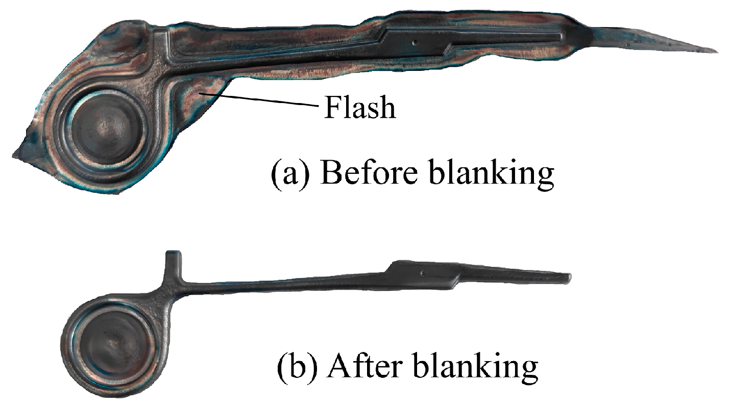
  • The shape of the flash after forging of surgical forceps blank is not exactly consistent, and it belongs to the special-shaped part.
  • The automatic transportation of flashes and finished products should be realized after blanking. Due to the small space between the upper and lower molds of the press, the limited operating space greatly increases the difficulty of automatic loading and unloading.

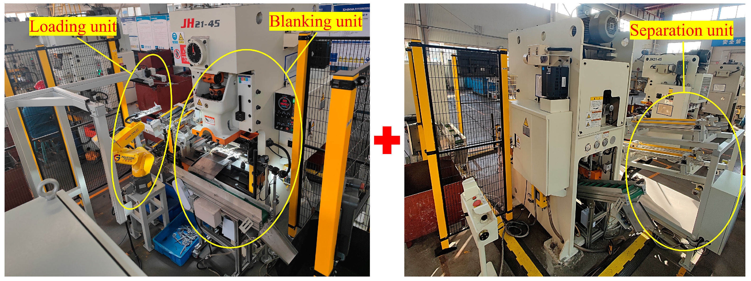
3. Modular Design of Workstation

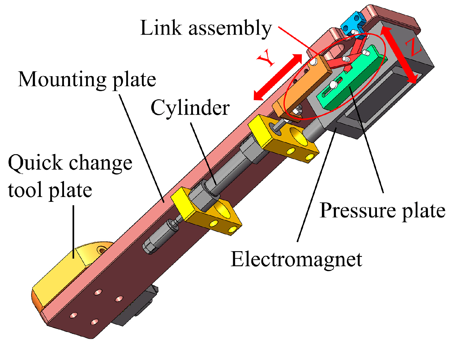
3.1. Design of Blank Fixture

The blank fixture consists of a mounting plate, a cylinder, an electromagnet, and a link assembly, as shown in Figure 2. Due to the complexity and inconsistency of surgical forceps blank features, traditional fixtures cannot work effectively. Therefore, this paper adopts the method of electromagnetic force adsorption. The function of the link assembly is to prevent the residual electromagnetic force causing the blank and fixture to fail to separate in time after the electromagnet is powered off. In the initial state, the cylinder is contracted and the surface of the pressure plate in the link assembly is lower than the surface of the electromagnet. The cylinder extends and moves in the Y-axis direction, pushing the pressure plate at the end of the link assembly in the Z-axis direction (shown in the red double arrows). As the robot grabs the blank and reaches the top of the mold, the cylinder starts working to separate the blank from the fixture.

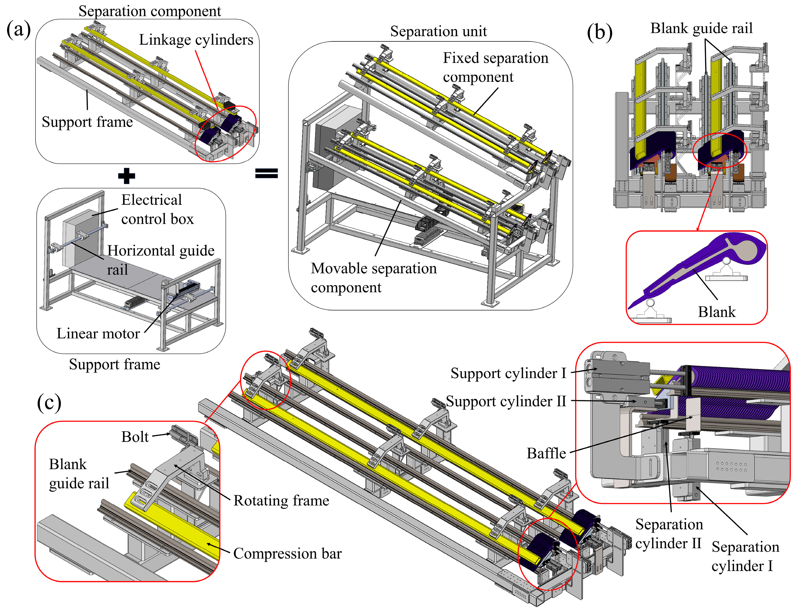
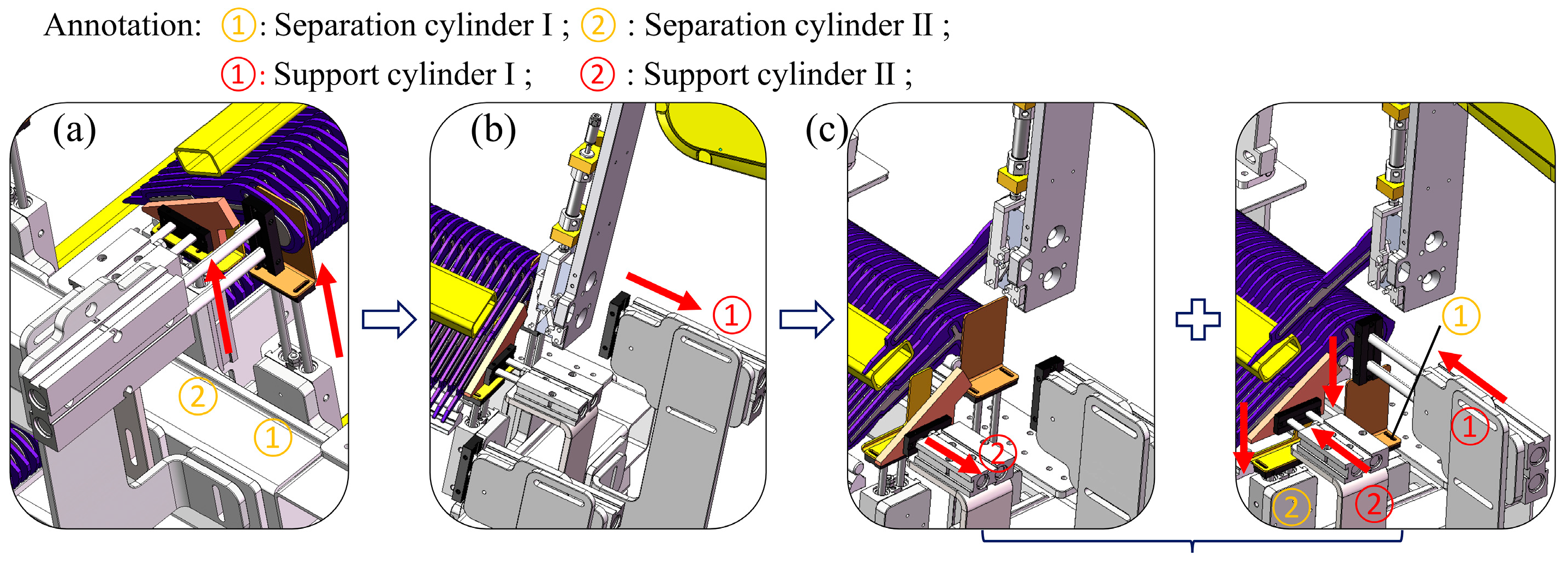
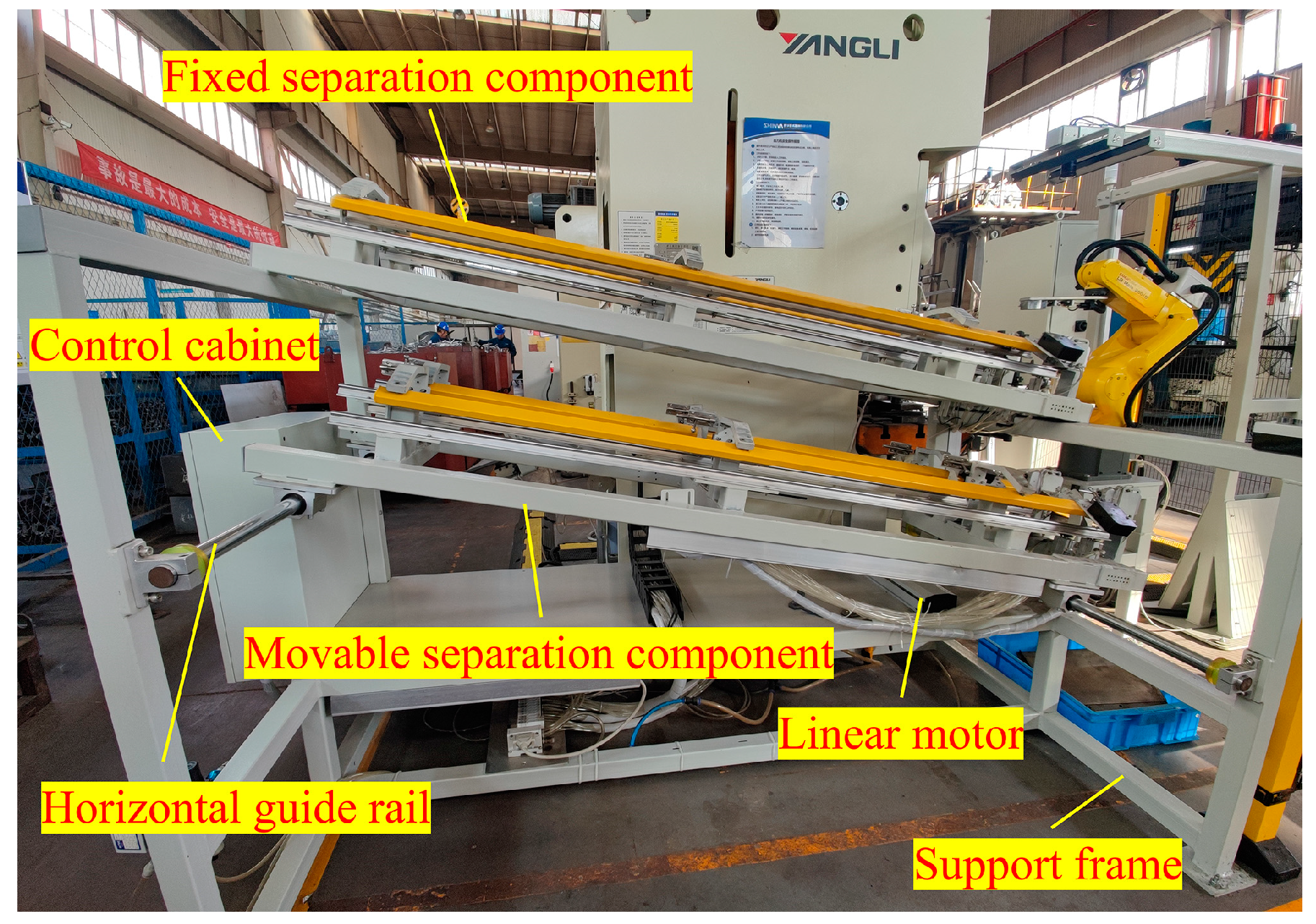
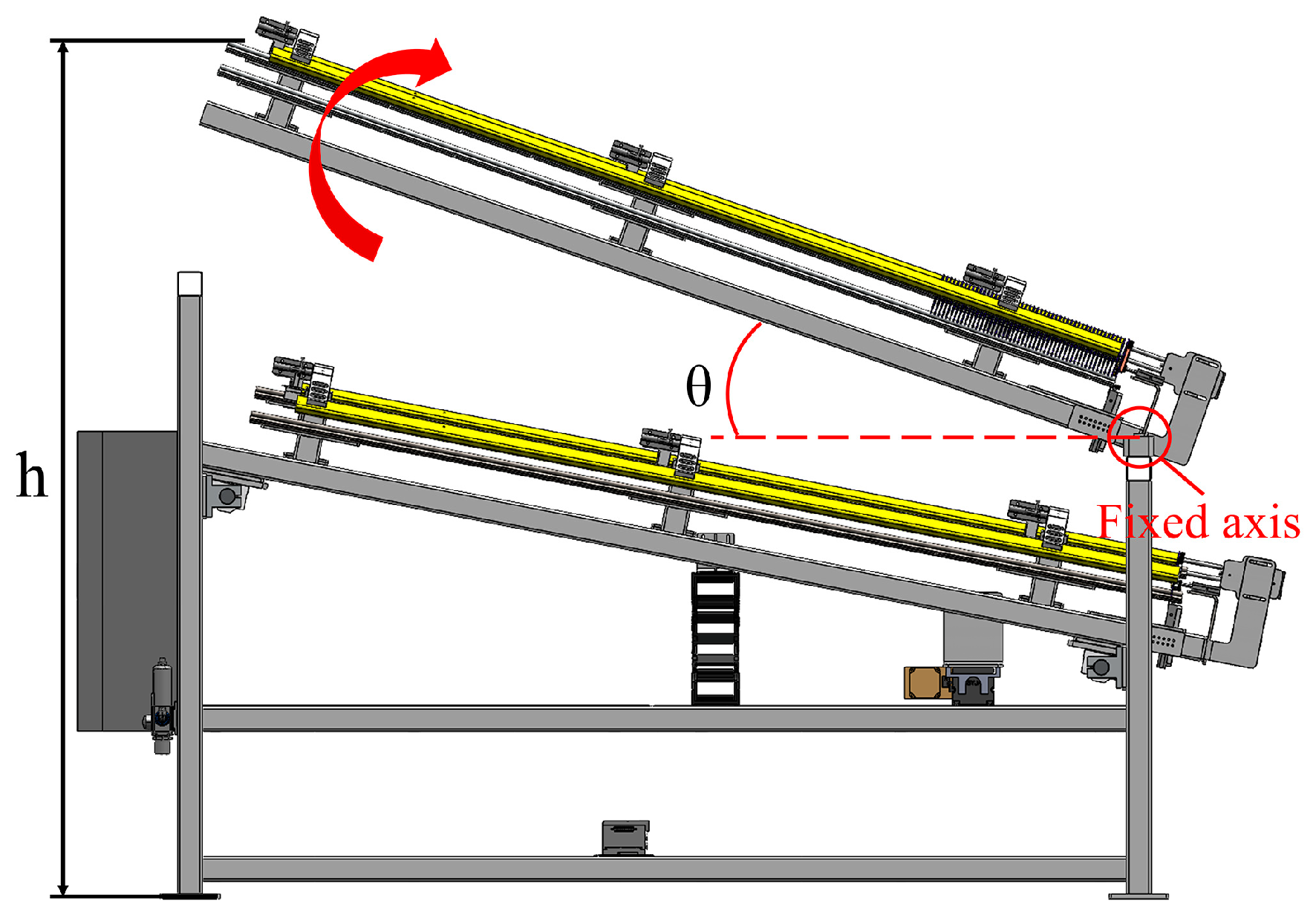
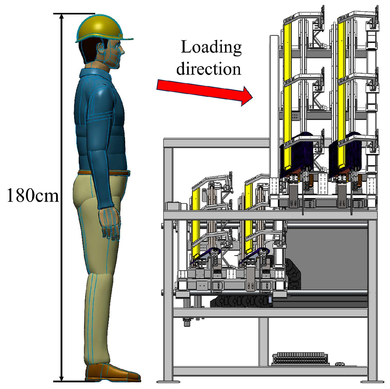
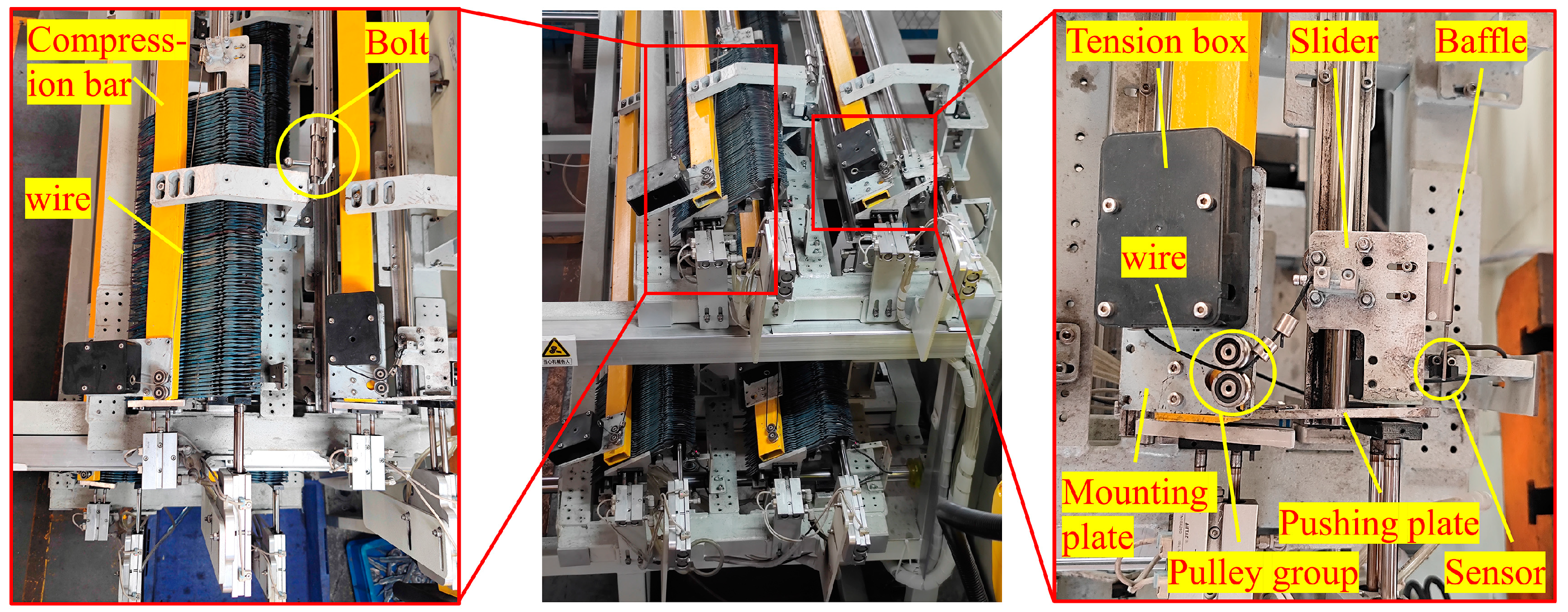
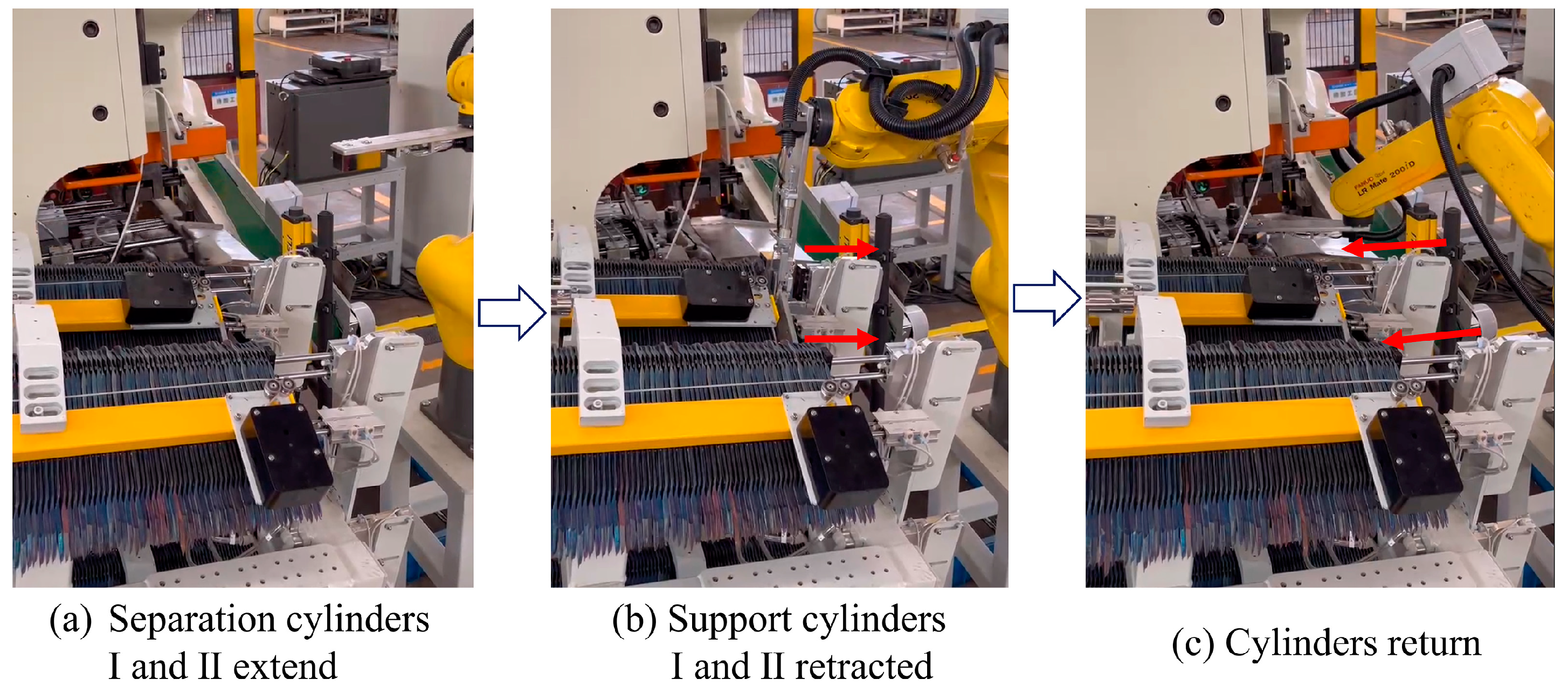
3.2. Design of Separation Unit

The separation unit consists of a support frame and separation components, as shown in Figure 3a, wherein the movable separation component can slide along the horizontal guide rail under the action of the linear motor to facilitate the input and output of the blanks. For the separation component, the design idea is to place the surgical forceps blanks on two guide rails arranged at an incline. After one piece is taken out by the linkage cylinders, the remaining blanks on the guide rail slide forward by gravity, and so on until all the blanks in the component are taken out, as shown in Figure 3b. The separation components are each provided with two storage bins, which can store enough blanks.
The separation component is shown in Figure 3c. The rotating frame is fitted with a compression bar to ensure the regularity of the blanks on the guide rail. After the blanks have been placed, the bolt is inserted into the locking holes of the rotating frame to achieve fixation. The front end of the surgical forceps blank is closely fitted with the supporting cylinders I and II. Then, the separation cylinders are extended to push the baffle into the blank gap. At this point, the support cylinders retract to realize the separation of the foremost blank.

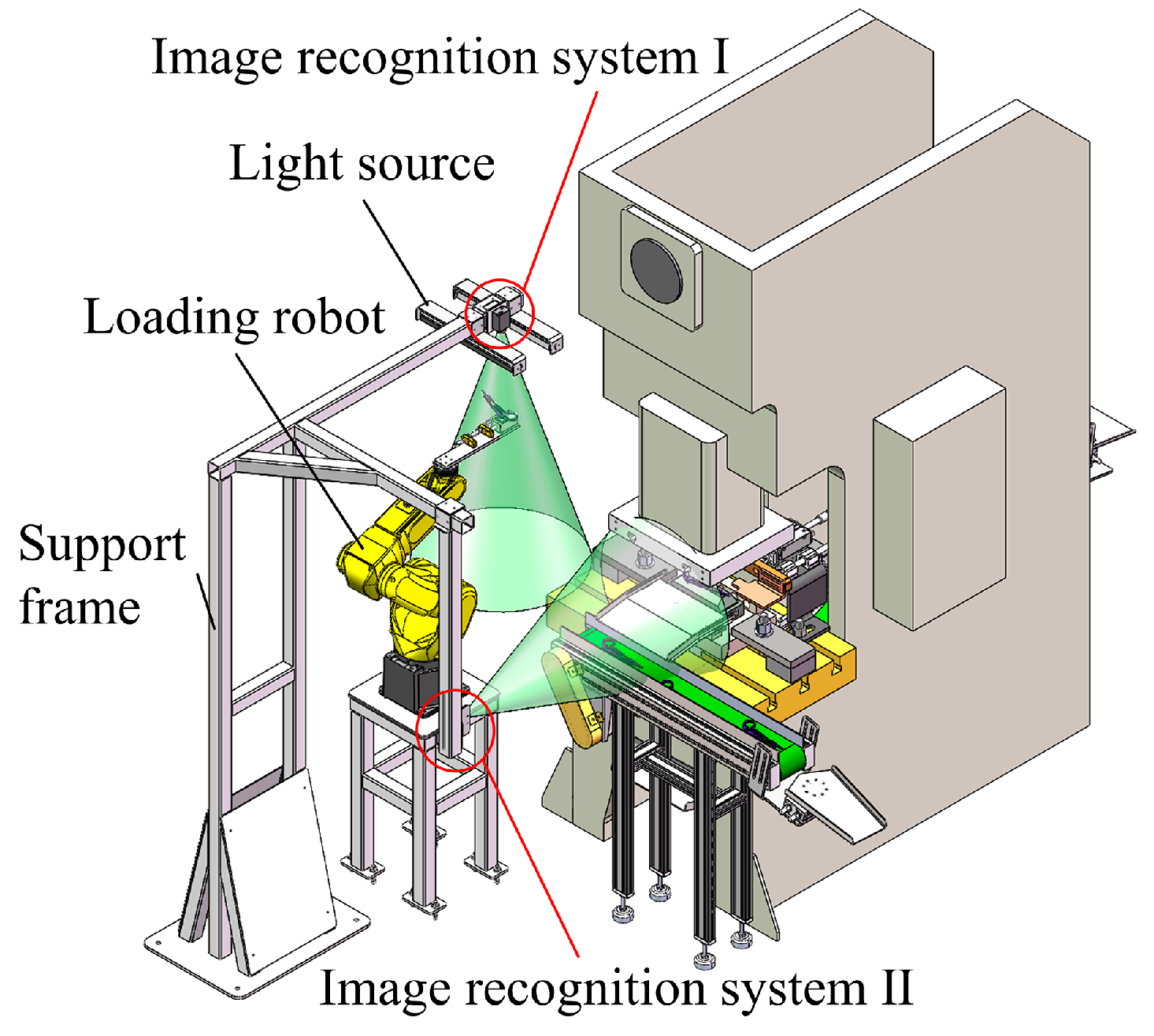
3.3. Design of Loading Unit

3.3.1. Design of General Structure

The loading unit consists of a loading robot, a support frame, a light source, and two image recognition systems, as shown in Figure 4. The light source is installed on both sides of the industrial camera of the image recognition system to ensure the clarity of the captured images. The loading robot grabs the surgical forceps blanks from the separation unit and places them into the blanking mold. The image recognition system I is used to detect the relative deviation of the blank from the fixture and output the correction parameters for the motion attitude of the robot end to ensure that the blank is accurately placed in the mold. The image recognition system II is used to detect the presence of blanks or flashes in the mold.

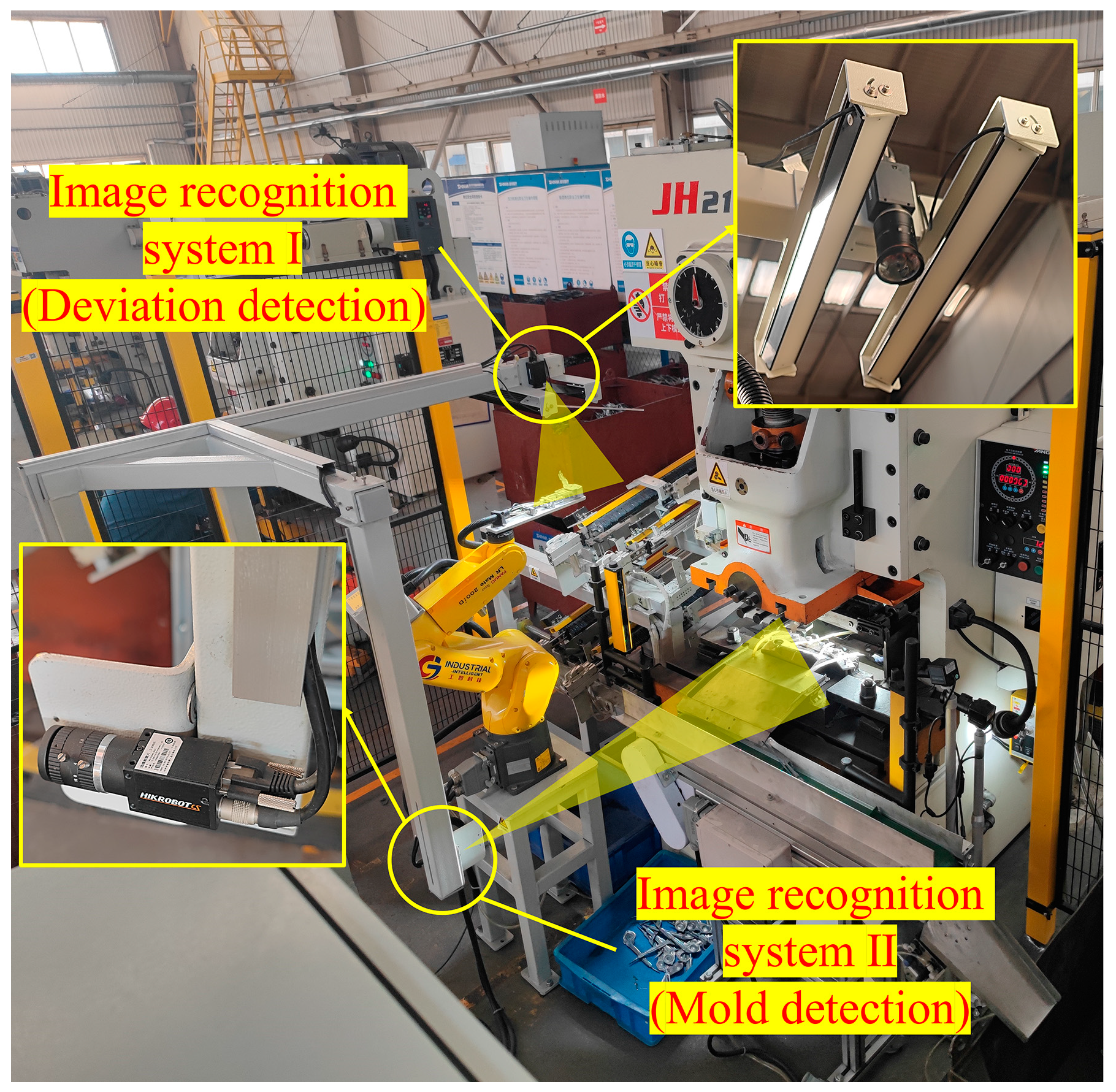
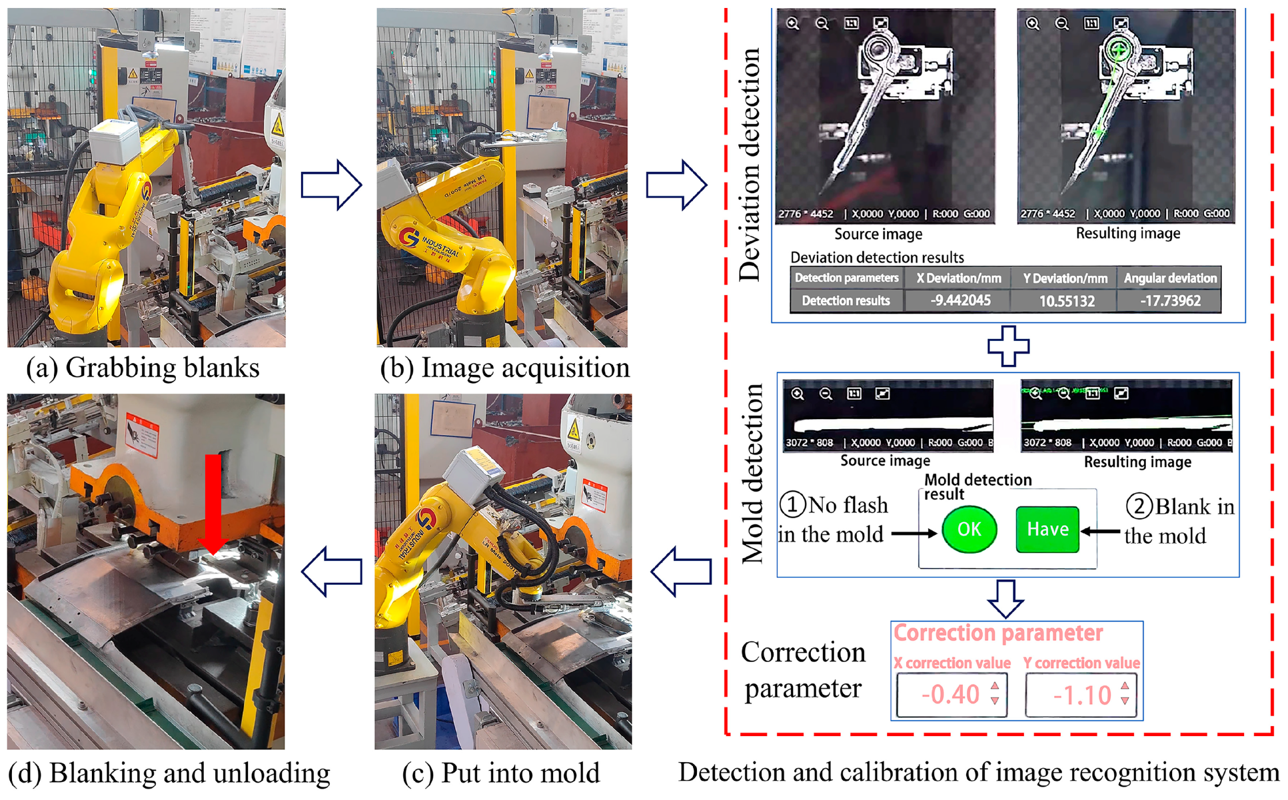
3.3.2. Design of the Image Recognition System

Due to the poor consistency of the blank flash, the separation unit can only achieve rough positioning. Therefore, when the robot grabs the blank, the relative position of the blank to the fixture changes depending on the shape of the flash. As shown in Figure 5, the most easily recognizable feature calibration points A1 and A2 are selected on the surgical forceps blank and the center of the electromagnet is used as a reference point. After collecting on-site photos through the industrial camera, the system will quickly output the resultant images and detection results.
After determining the actual calibration point, the image recognition system I can calculate the relative deviation between the actual calibration point and the standard calibration point by comparing it with the standard model, including the positional deviation in the x and y directions and the angular deviation. The system will give correction parameters according to the inspection results and make up for the deviation by adjusting the motion of each robot joint, so that the blank can be accurately placed into the mold.
The image recognition system II has two tasks. Firstly, before the robot puts the blank into the mold, it detects if there are any flashes left in the mold after the previous blanking. If present, the robot will not continue to place the blank and the system will issue an alarm. Secondly, the presence of blanks in the mold is tested before the work of the press to avoid ineffective blanking.

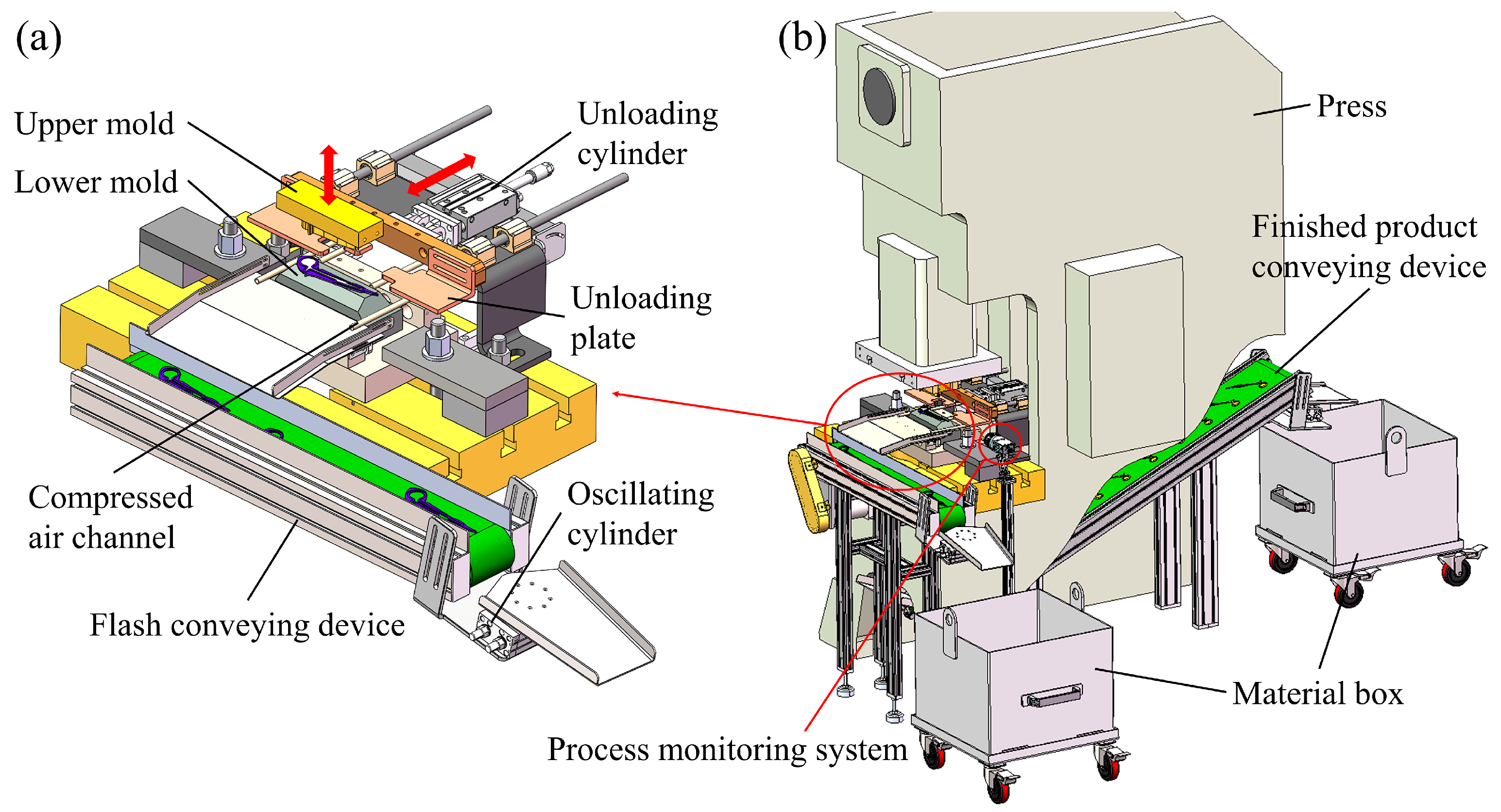
3.4. Design of the Blanking Unit

The blanking unit consists of a press, two conveying devices, and a process monitoring system, as shown in Figure 6b. The conveying device realizes the automatic conveying of finished products and flashes after blanking. The process monitoring system monitors the working process of the press in real time through a camera and stores the operation video for technical review. Technicians can observe the work status through the monitor screen and make timely decisions when unexpected situations arise.
The layout of the blanking worktable is shown in Figure 6a. After the robot puts the blank into the mold, the unloading cylinder pushes the unloading plate out. The upper mold passes through the unloading plate and excises the flash, which prevents the flash from getting stuck on the mold. At the end of blanking, the unloading cylinder returns to its initial position. At this point, the compressed air blows the flash into the flash conveying device in front, and the finished product falls into the finished product conveying device below the press. The oscillating cylinders are installed at the end of the conveying device to make the flashes and finished products fall into the material box evenly through continuous oscillation.

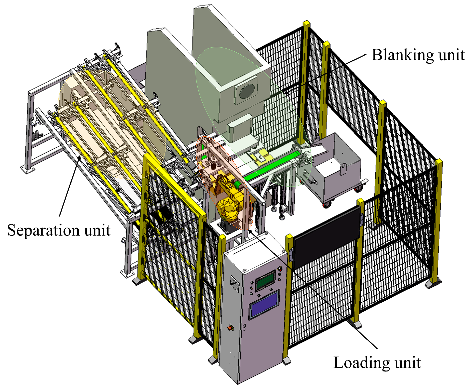
3.5. System Integration Based on Modular Design

The modular design divides production requirements into functional modules, allowing rapid development, design, and maintenance [7]. When developing automation equipment based on modular design methods, the functional modules divided should facilitate the configuration of a complete processing system. By arranging and combining functional modules, designers can quickly generate automated workstations. After system integration, it is possible to adapt the processing of different models of surgical forceps by replacing or adding new modules. In this paper, three functional modules are divided according to the production process of surgical forceps, as shown in Table 1. According to the designed functional modules, the overall structure of the combined workstation is shown in Figure 7.

4. Process Method for Workstation

4.1. Overview of Process Method

Based on the designed workstation, a process method is proposed for automatic blanking of surgical forceps parts. This method can be summarized in the following three steps.
(1) Pre-storage of blanks: The separation unit allows pre-storage of surgical forceps blanks and ensures the continuity of subsequent blanking work. Firstly, the rotating frame opens and the linear motor drives the movable separation component to the outermost end, which facilitates the placement by the workers, as shown in Figure 8a. Secondly, the worker picks up the surgical forceps blanks from the material box and arranges them on the guide rails of the separation component, as shown in Figure 8b. After placing, the rotating frame is fixed with bolts. The rotating frame does not contact directly with the blanks, only as a protective case to ensure the uniformity of the blanks on the guide rail. The linear motor drives the movable separation component to move along the horizontal guide rail to the innermost end, which facilitates the grabbing of blanks by the robot, as shown in Figure 8c.
(2) Separation of blanks: After the blanks are placed, since the separation component is inclined, the foremost blanks will fit closely to the support cylinders under gravity. At this time, the separation cylinder extends so that the baffle is inserted into the gap between the blanks, as shown in Figure 9a. Then, the support cylinder I retracts to create a larger space between its front end and the blank. The robot attitude is adjusted so that the side of the fixture with the electromagnet is close to the foremost blank, as shown in Figure 9b. When the fixture absorbs the blank, the support cylinder II retracts and the remaining blanks do not slide downward due to the obstruction of the separation cylinder. Then, the robot grabs the blank and raises it a certain distance, waiting for the separation cylinder I to retract before the support cylinder I extends out. Similarly, after the separation cylinder II is retracted, the support cylinder II is extended. At this point, the blanks in the component are re-obstructed by the support cylinders, waiting for the next cycle to begin, as shown in Figure 9c.
(3) Identification and blanking of blanks: After grabbing the surgical forceps blank from the separation unit, the robot adjusts its attitude so that the blank is oriented towards the industrial camera of the image recognition device, as shown in Figure 10a. After analysis and calibration by the image recognition system, the attitude of the robot when placing the blank is adjusted so that the blank is accurately placed into the lower mold, as shown in Figure 10b. At this time, the unloading cylinder extends and the upper mold passes through the unloading plate to remove the flash. The flash is blown under the action of compressed air onto the conveyor belt of the conveying device and the finished product falls onto the conveyor belt below the press. The oscillating cylinder at the end of the conveying device continuously oscillates so that the finished products and flashes fall evenly into the material box, as shown in Figure 10c.

4.2. Flexibility and Limitations

The automatic blanking workstation for surgical forceps blanks is based on the system integration of functional modules. Although the separation unit, loading unit, and blanking unit are developed for the specific production object, the processing method and device proposed in this paper are still highly flexible. The flexibility of this scheme is shown in Figure 11 and is illustrated in the following three areas.
The surgical forceps blanks rely on two guide rails in the separation component for storage and positioning, and the spacing of the guide rails can be changed through slots in the mounting base. Moreover, the mold of the press can be changed to adapt to different types of surgical forceps or similar parts.
The blank fixture works with electromagnetic force, so it is not limited to specific shapes and can realize most machining tasks.
Due to the poor consistency of the blank flash, the positioning error of the separation component occurs. Therefore, the relative position of the blank and fixture differ each time the robot grabs it. However, the image recognition system can compensate for the relative deviation between the blank and the fixture and ensure that the blank is accurately placed in the mold by adjusting the robot’s attitude when placing the blank. It can also adapt to different types of surgical forceps.
The steel plates are forged to form surgical forceps blanks and then placed into the material box disorganized, resulting in a very messy distribution. The method proposed in this paper cannot realize the automatic sorting of blanks and place them into the separation unit, which still needs to be placed manually. The frequent replenishment of blanks by workers during the production process will seriously affect the productivity of the workstation. The separation unit has been equipped with fixed and movable separation components to reduce the manual participation rate as much as possible. Enough blanks can be stored in advance to ensure production continuity. Although most of the workstation processes have been automated, the above issues will still result in high labor costs and limit production efficiency.
The improvement scheme as shown in Figure 12 will be researched in future work to realize the fully automated operation of the workstation. The blank sorting and placement module has been added to the original workstation. After the material box with surgical forceps blanks is conveyed to the underside of the vision inspection system, the system will detect the position information of the current easily gripped blanks and transmit it to the robot control system. The robot grips the blank and then places it on a calibration table for secondary calibration to ensure that the attitude of the blank is consistent each time it is gripped. Finally, the robot places the blanks one by one into the separation unit through specific trajectory programs.

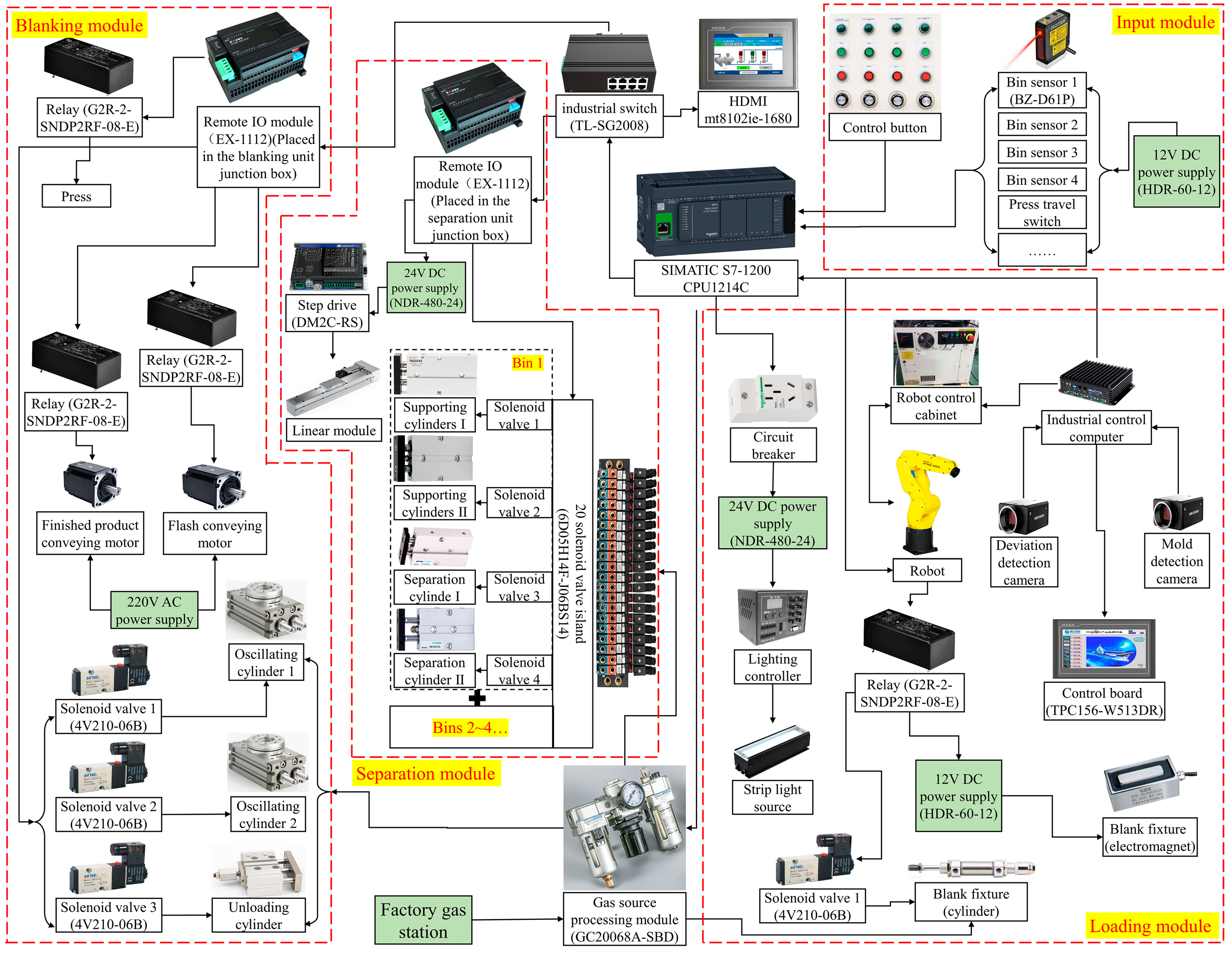
5. Equipment Selection and Control System Design

After completing the workstation program design, an experimental platform must be built to verify its feasibility and stability. According to the designed 3D model, some parameter information of mechanical components can be obtained, including cylinder stroke, profile size, guide length, etc., to facilitate accurate selection. For mechanical components with a wide range of availability, such as motors, industrial cameras, strip light sources, industrial control computers, etc., the selection must consider their actual parameters and the needs of the workstation. For the support frames of the separation device and the image recognition system, it is sufficient to select the corresponding profiles and then weld them according to the engineering drawings derived from the model. Therefore, under the premise of combining practical needs and costs, the main mechanical components required to build the workstation experiment platform are shown in Table 2.
According to the process method proposed in this paper, the design of the workstation control system is completed, as shown in Figure 13. The system is divided into an input module, a separation module, a loading module, and a blanking module, and the control flow corresponds to the process flow in Section 4.1. The control system is centered on the SIMATIC S7-1200, which can efficiently process the detection signals input from the sensors and accurately transmit the control signals to the actuating devices. The control system uses a large number of electrical components, such as solenoid valves, relays, photoelectric sensors, etc., the specific models have been labeled in the system diagram. An additional remote IO module (EX-1112) is added to the separation module and the blanking module, which can convert the input/output signals of the field equipment into digital signals transmitted through the profinet communication protocol. The remote IO module realizes the centralized control and monitoring of multi-level equipment and improves the reliability and efficiency of the production process.

6. Experiment and Discussion

Based on the functional modules designed and processing methods proposed in this paper, an experimental prototype of the automatic blanking workstation for surgical forceps was built, as shown in Figure 14.

6.1. Reliability Analysis of Separation Device

The experimental prototype of the separation unit is shown in Figure 15. Multi-cylinder linkage is the key to the successful separation of blanks, and its success rate and stability directly affect the efficiency of the workstation. During the experiments, it was found that the separation unit often had problems resulting in the blanks not being separated. In the ideal state, since the separation component is inclined, when one blank is removed, the remaining blanks placed on the guide rail will keep sliding forward under the action of gravity to realize continuous production. However, in actual production, due to the existence of large friction between the blank and the guide rail, the expected results cannot be achieved.
To further analyze the effect caused by friction on blank sliding, a simplified force model is established in this section, as shown in Figure 16. The blank on the guide rail is simplified into three parts: front, middle, and back. The forces on each part of the blank are given in the following equations, respectively.
G 1 x + F 1 > F f 1 G 1 sin θ + F 1 > μ G 1 cos θ
G 2 x + F 2 > F f 2 G 2 sin θ + F 2 > μ G 2 cos θ
G 3 x < F f 3 G 3 sin θ < μ G 3 cos θ
where G is the force of gravity, Gx and Gy are the component forces of gravity in the x and y directions, F is the thrust force given by the blank behind it, Ff is the friction force acting on the blank, and θ is the inclination angle of the separation component.
For the first two portions of the blank, the blanks will fit tightly together and keep sliding forward because the component forces of thrust and gravity are greater than the friction. The end part of the blank is almost only affected by the component force of gravity in the X-axis direction, resulting in G3x < Ff3. For a single blank, Gx acts on the center of mass, while Ff acts on the contact surface between the guide rail and the blank. Therefore, the unbalanced forces Fa and Fb are generated, causing the blank to tilt gradually during the sliding process. As the blank on the guide rail is gradually taken out, the tilt phenomenon will become more serious, resulting in the separation component not working properly. Theoretically, when θ increases to a certain value, the following equation occurs according to the characteristics of the sine and cosine function:
G 3 x > F f 3 G 3 sin θ > μ G 3 cos θ
In the current scheme, the separation component is inclined at an angle of 11°. As shown in Figure 17, an inclination experiment is carried out using the separation component to investigate whether increasing the inclination angle (θ) can improve the above phenomenon. The lower end of the separation component is used as the rotation axis, and the other end is continuously raised. Record the variation of the inclination angle and the end height to obtain the data shown in Table 3. Through experiments, it is found that when the inclination angle of the separation component reaches 25°, the movement state of the blank on the guide rail is consistent with the ideal situation. In this case, the separation unit enables continuous separation of the blanks.
After setting the inclination angle of the separation component to 25°, the state of the separation unit is shown in Figure 18. Since the press is installed on the right side of the separation unit, workers can only load from the left side. In the case of a worker with a height of 180 cm, for example, the high end of the separation component largely increases the difficulty of loading. Therefore, the scheme is not feasible.
The blank locking device is designed after comprehensive analysis, as shown in Figure 19. The locking device mainly consists of a mounting plate, a tension box, a slider, a pulley group, a pushing plate, a baffle, and a sensor, wherein the tension box is internally provided with a coil. As the wire in the coil is pulled out, the tension box generates continuous tension. The mounting plate is fixed to the compression bar, and its upper surface is used to mount the pulley group and tension box. The front end of the slider is installed with a pushing plate, and the side is installed with a baffle. When all the blanks in the separation component have been taken out, the baffle notifies the staff to replenish the blanks by triggering the sensor. The wire in the tension box is fixed to the slider after passing through the pulley group. After the surgical forceps blanks are placed on the guide rails, the pushing plate at the front end of the slider continues to extrude the blanks under the action of the tension box. As the blanks are taken out, the slider slides forward along the guide rail, so that the blanks are always in a tight fit state.
After continuous production experiments, the blank locking device works stably, and the multi-cylinder linkage can take out the blanks smoothly with a success rate of 100%. About 3000 blanks can be stored in the separation unit, which ensures continuous production. The stability verification process of the separation component is shown in Figure 20. After improvement, the reliability of the separation unit is substantially increased and can be used in actual production.

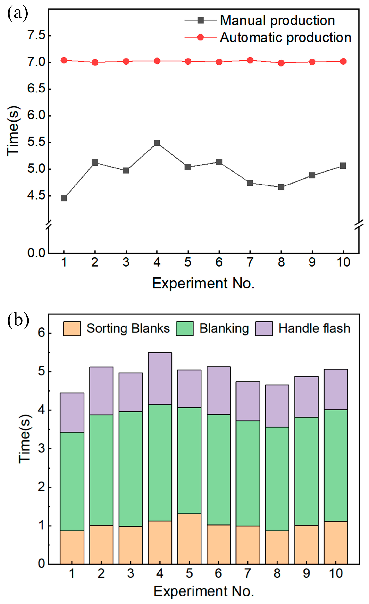
6.2. Analysis of Workstation Efficiency

The detection speed and accuracy of the image recognition system directly determines the productivity and product quality of the workstation. The image recognition system has set up two industrial cameras, as shown in Figure 21. One is responsible for detecting the relative deviation between the blank and the fixture, and the other is responsible for detecting the presence of flashes or blanks on the mold. The complete working process of the image recognition system includes collecting on-site pictures, calculating relative deviation, detecting mold, and outputting correction parameters.
The reliability verification process of the image recognition system is shown in Figure 22. In the continuous production process, the average detection speed of the system can reach 100 ms/piece, and the product qualification rate can reach 95.7%. It can meet the requirements of fast detection speed and high recognition accuracy, and can be used in actual production.
In the continuous production experiment, the average time of each process is shown in Table 4. The results show that the process of the robot picking up the blanks and then placing them into the mold takes up more time. For both production methods, manual and automatic, some preparation is required before production can begin. Before manual production, workers need to convey the blank boxes near the press. Before automatic production, workers need to arrange the blanks into the separation unit. On the premise that all the preparatory work has been completed, on-site processing experiments using the two production methods are performed to obtain Figure 23. Each group of experiments is the average value calculated In the case of processing 300 blanks.
The results show that the uncertainty of manual production leads to a large deviation in the processing time of the product. Although automatic machining processes take more time, stable machining time is more conducive to production planning. Approximately 3000 blanks can be stored in the separation unit, allowing the workstation to run continuously for approximately 5.8 h. The workstation can work continuously, while the workers need rest periods. Therefore, the average daily output of manual labor is about 4000 pieces, while the average daily output of a workstation can reach 4500 pieces.
After the worker has placed the blanks in the separation unit, the blanks can be replenished at any time according to the signals from the sensors in the blank locking device, realizing uninterrupted production. It takes 0.18 h for a worker to replenish a bin in the separation unit, while it takes 1.45 h for the robot to remove all the blanks in the bin. Considering the need to inspect workstations and deal with emergencies, one worker could theoretically supervise five workstations at the same time. The actual benefits to the enterprise will increase dramatically with the increase in the number of workstations, labor costs will be reduced significantly, and more importantly, safety accidents will be avoided.

6.3. Stability Analysis of Workstation

Conducting long-term production tests is beneficial in verifying the reliability of the workstation and identifying potential problems. On the basis of testing the reliability of the separation device and the efficiency of the workstation, Table 5 shows the data obtained from the continuous operation of the workstation for three months. First, the success rate of the separation device is stabilized at 100% after the workers have placed the blanks correctly. The average daily output of the workstation is stabilized at about 4500 pieces, and the defective rate is within a reasonable range. In the group 1 and 3 experiments, the workstation issued an alarm, mainly because the vision system II detected that the flash after the last blanking was not blown off, which affected the robot’s next loading. After manual intervention to remove the flashes, the workstation returned to normal operation. The results of long-term testing show that the workstation has a high reliability and success rate, effectively reducing the maintenance costs in the later period.

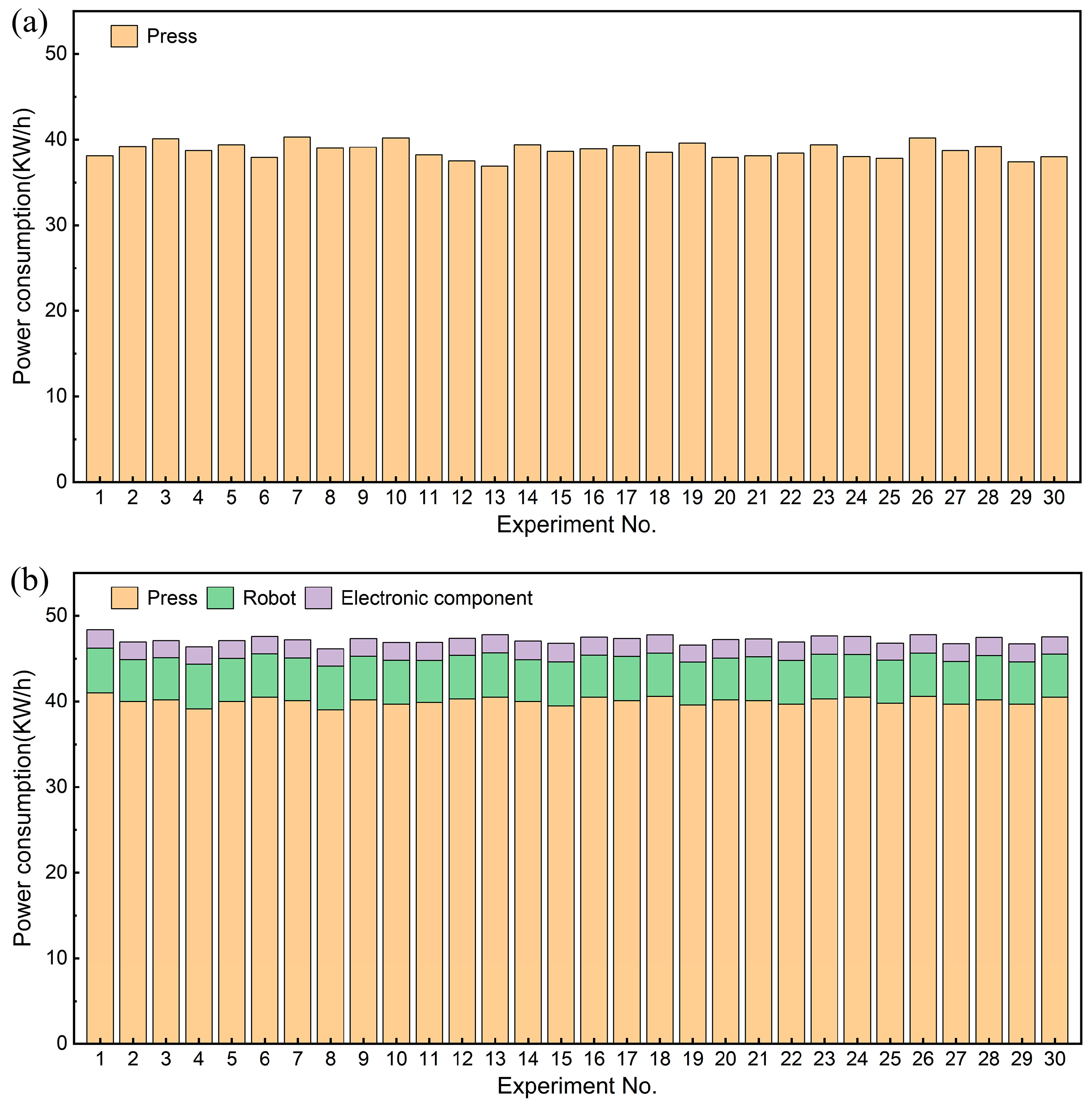
6.4. Power Consumption Analysis of the Workstation

Through the relevant feasibility, efficiency, and stability test analysis, the workstation already has the conditions for engineering application. The test results show that the workstation effectively reduces labor costs and maintenance costs. It is necessary to conduct power consumption comparison experiments before and after adding the automation module to further analyze the advantages and drawbacks of the automation module. Before adding the automation module, the power consumption of the press is the total power consumption. After adding the automation module, the total power consumption mainly consists of robot power consumption, press power consumption, and electrical power consumption.
The main motor power of the press is 5.5 KW, while the average power of the robot (FANUC LR Mate 200iD) is 0.5 KW, and the workload is very small, so theoretically, the robot power consumption is much less than the press power consumption. The running data for 30 consecutive days were selected from the history records of the past experiments, and the power consumption before and after the addition of the automation module (9 h of operation per day) was obtained shown in Figure 24. The results show that the power consumption generated by the addition of the automation module is quite small. Due to the higher output during automatic production, the power consumption of the press has also increased. Combined with the results in Section 6.2, it can be seen that as the number of workstations increases, the power consumption generated is not significant while reducing labor costs and increasing productivity.

7. Conclusions

In the work of this paper, the automatic blanking of surgical forceps blanks was realized through modular design and functional integration. The experimental results showed that the surgical forceps blanking workstation can be applied in actual production. The main conclusions are drawn as follows.
The blank fixture, separation unit, loading unit, and blanking unit were designed, and the corresponding processing method was proposed. The separation unit realized the pre-storage and continuous separation of the blanks, but the blanks still need to be manually placed in the separation unit before production. The loading unit realized the blank deviation calibration and correction, which can accurately put the blank into the mold. The blanking unit realized the automatic blanking of blanks as well as the automatic conveying of finished products and flashes. The processing of different types of surgical forceps can be realized through the adjustment and replacement of functional modules.
The models and specifications of key components were selected according to the workstation design program to build the test platform, and the workstation control system corresponding to the process flow was designed.
The experimental results showed that the blank locking device solved the problem of uneven force on blanks leading to the failure of the separation device, and the success rate of separation was stabilized at 100%. The average detection speed of the image recognition system can reach 100 ms/piece, and the product qualification rate can reach 95.7%. Compared to manual production, automatic production has resulted in a 12.5% increase in productivity. Finally, the superiority of the workstation is further illustrated by the long-term test experiment and the comparative analysis of power consumption, which proves that the workstation has strong stability and little extra power consumption.

Author Contributions

Conceptualization, X.D. and J.L.; methodology, Z.L. (Zhenyu Li); model, X.D.; validation, Y.L., J.L. and H.W.; investigation, Z.L. (Zhenyu Li); resources, Z.L. (Zhiyuan Li) and H.W.; data curation, X.D.; writing—original draft preparation, X.D.; writing—review and editing, J.L.; visualization, Y.L., J.L. and H.W.; supervision, Y.L. and J.L.; project administration, H.W. All authors have read and agreed to the published version of the manuscript.

Funding

This research was funded by the National Natural Science Foundation of China Youth Fund (grant number 51505265) and research funding for the education project from China Educational Ministry (grant number 20230101644).

Data Availability Statement

Data are contained within the article.

Conflicts of Interest

Author H.W. was employed by Shandong Gongzhi Technology Co., Ltd. The remaining authors declare that the research was conducted in the absence of any commercial or financial relationships that could be construed as a potential conflict of interest.

References

  1. Aravind, U.; Chakkingal, U.; Venugopal, P. A Review of Fine Blanking: Influence of Die Design and Process Parameters on Edge Quality. J. Mater. Eng. Perform. 2021, 30, 1–32. [Google Scholar] [CrossRef]
  2. Sahli, M.; Roizard, X.; Assoul, M.; Colas, G.; Giampiccolo, S.; Barbe, J.P. Finite element simulation and experimental investigation of the effect of clearance on the forming quality in the fine blanking process. Microsyst. Technol. 2021, 27, 871–881. [Google Scholar] [CrossRef]
  3. Zal, V.; Naeini, H.M.; Bahramian, A.R.; Abbaszadeh, B. Experimental evaluation of blanking and piercing of PVC based composite and hybrid laminates. Adv. Manuf. 2016, 4, 248–256. [Google Scholar] [CrossRef]
  4. Li, G.; Long, X.; Yang, P.; Liang, Z. Advance on friction of stamping forming. Int. J. Adv. Manuf. Technol. 2018, 96, 21–38. [Google Scholar] [CrossRef]
  5. Liu, Y.; Cheng, T.; Hua, L.; Mao, H. Research on the effect of ultrasonic vibration on the roll-over during the fine blanking process. J. Mech. Sci. Technol. 2017, 31, 835–843. [Google Scholar] [CrossRef]
  6. Ma, J.; Kremer, G.E.O. A systematic literature review of modular product design (MPD) from the perspective of sustainability. Int. J. Adv. Manuf. Technol. 2016, 86, 1509–1539. [Google Scholar] [CrossRef]
  7. Zhang, Z.-Y.; Wang, X.-D.; Ren, T.-Q.; Jin, T.-L. Novel gripper module and method for automated assembly of miniature parts. Adv. Manuf. 2023, 11, 295–310. [Google Scholar] [CrossRef]
  8. Ostrosi, E.; Fougères, A.-J.; Zhang, Z.-F.; Stjepandić, J. Intelligent modular design with holonic fuzzy agents. Adv. Manuf. 2021, 9, 81–103. [Google Scholar] [CrossRef]
  9. Salvador, F. Toward a Product System Modularity Construct: Literature Review and Reconceptualization. IEEE Trans. Eng. Manag. 2007, 54, 219–240. [Google Scholar] [CrossRef]
  10. Bonvoisin, J.; Halstenberg, F.; Buchert, T.; Stark, R. A systematic literature review on modular product design. J. Eng. Des. 2016, 27, 488–514. [Google Scholar] [CrossRef]
  11. Moosavian, A.; Xi, F. Modular design of parallel robots with static redundancy. Mech. Mach. Theory 2016, 96, 26–37. [Google Scholar] [CrossRef]
  12. Vega-Heredia, M.; Mohan, R.E.; Wen, T.Y.; Aisyah, J.S.; Vengadesh, A.; Ghanta, S.; Vinu, S. Design and modelling of a modular window cleaning robot. Autom. Constr. 2019, 103, 268–278. [Google Scholar] [CrossRef]
  13. Zhang, B.; Hu, C.; Yang, P.; Liao, Z.; Liao, H. Design and Modularization of Multi-DoF Soft Robotic Actuators. IEEE Robot. Autom. Lett. 2019, 4, 2645–2652. [Google Scholar] [CrossRef]
  14. Song, Z.; Liu, C.; Chai, F.; Zhao, H. Modular Design of an Efficient Permanent Magnet Vernier Machine. IEEE Trans. Magn. 2020, 56, 7506406. [Google Scholar] [CrossRef]
  15. Giusti, A.; Althoff, M. On-the-Fly Control Design of Modular Robot Manipulators. IEEE Trans. Control Syst. Technol. 2018, 26, 1484–1491. [Google Scholar] [CrossRef]
  16. Lu, S.; Ahmad, Z.; Zoppi, M.; Ding, X.; Zlatanov, D.; Molfino, R. Design and Testing of a Highly Reconfigurable Fixture with Lockable Robotic Arms. J. Mech. Des. 2016, 138, 085001. [Google Scholar] [CrossRef]
  17. Yu, S.; Ye, C.; Tao, G.; Ding, J.; Wang, Y. Design and analysis of a modular rope-climbing robot with the finger-wheeled mechanism. J. Mech. Sci. Technol. 2021, 35, 2197–2207. [Google Scholar] [CrossRef]
  18. Bai, Y.; Sun, L.; Zhang, M. Design and analysis of multistage adaptive lateral deformation tracked robot. J. Mech. Sci. Technol. 2022, 36, 371–383. [Google Scholar] [CrossRef]
  19. Ji, W.; Wang, L. Industrial robotic machining: A review. Int. J. Adv. Manuf. Technol. 2019, 103, 1239–1255. [Google Scholar] [CrossRef]
  20. Kodaira, N. Expected innovation in industrial robots. Adv. Robot. 2016, 30, 1088–1094. [Google Scholar] [CrossRef]
  21. Li, Z.; Li, S.; Luo, X. An overview of calibration technology of industrial robots. IEEE/CAA J. Autom. Sin. 2021, 8, 23–36. [Google Scholar] [CrossRef]
  22. Kurka, P.R.G.; Díaz Salazar, A.A. Applications of image processing in robotics and instrumentation. Mech. Syst. Signal Process. 2019, 124, 142–169. [Google Scholar] [CrossRef]
  23. Ruan, D.; Zhang, W.; Qian, D. Feature-based autonomous target recognition and grasping of industrial robots. Pers. Ubiquitous Comput. 2023, 27, 1355–1367. [Google Scholar] [CrossRef]
  24. Gao, M.; Li, X.; He, Z.; Yang, Y. An Automatic Assembling System for Sealing Rings Based on Machine Vision. J. Sens. 2017, 2017, 4207432. [Google Scholar] [CrossRef]
  25. Dhiman, A.; Shah, N.; Adhikari, P.; Kumbhar, S.; Dhanjal, I.S.; Mehendale, N. Firefighting robot with deep learning and machine vision. Neural Comput. Appl. 2022, 34, 2831–2839. [Google Scholar] [CrossRef]
  26. Ayyad, A.; Halwani, M.; Swart, D.; Muthusamy, R.; Almaskari, F.; Zweiri, Y. Neuromorphic vision based control for the precise positioning of robotic drilling systems. Robot. Comput.-Integr. Manuf. 2023, 79, 102419. [Google Scholar] [CrossRef]
  27. Banafian, N.; Fesharakifard, R.; Menhaj, M.B. Precise seam tracking in robotic welding by an improved image processing approach. Int. J. Adv. Manuf. Technol. 2021, 114, 251–270. [Google Scholar] [CrossRef]
  28. Koskinopoulou, M.; Raptopoulos, F.; Papadopoulos, G.; Mavrakis, N.; Maniadakis, M. Robotic Waste Sorting Technology: Toward a Vision-Based Categorization System for the Industrial Robotic Separation of Recyclable Waste. IEEE Robot. Autom. Mag. 2021, 28, 50–60. [Google Scholar] [CrossRef]
  29. Wang, Z.; Li, P.; Zhang, H.; Zhang, Q.; Ye, C.; Han, W.; Tian, W. A binocular vision method for precise hole recognition in satellite assembly systems. Measurement 2023, 221, 113455. [Google Scholar] [CrossRef]
Figure 1. Comparison of surgical forceps blanks before and after blanking.
Machines 12 00556 g001
Figure 2. Blank fixture.
Machines 12 00556 g002
Figure 3. Design of separation unit: (a) structure of separation unit, (b) attitude of blank placement, and (c) structure of separation component.
Machines 12 00556 g003
Figure 4. Structure of loading unit.
Machines 12 00556 g004
Figure 5. Detection principle diagram of the image recognition system.
Machines 12 00556 g005
Figure 6. Design of blanking unit: (a) blanking worktable; (b) overall structure of the blanking unit.
Machines 12 00556 g006
Figure 7. System integration of functional modules.
Machines 12 00556 g007
Figure 8. Flow diagram of blank storage: (a) bin shift, (b) blank placement, and (c) bin returns.
Machines 12 00556 g008
Figure 9. Flow diagram of blank separation: (a) blank separation, (b) fixture in place, and (c) blank gripping and cylinder reset.
Machines 12 00556 g009
Figure 10. Flow diagram of blank identification and blanking: (a) deviation detection, (b) blank placement, and (c) blanking and conveying.
Machines 12 00556 g010
Figure 11. Flexibility of the workstation.
Machines 12 00556 g011
Figure 12. Improvement scheme of workstation.
Machines 12 00556 g012
Figure 13. Workstation control system diagram.
Machines 12 00556 g013
Figure 14. Site layout of the workstation.
Machines 12 00556 g014
Figure 15. Experimental prototype of the separation unit.
Machines 12 00556 g015
Figure 16. Simplified force model of blank.
Machines 12 00556 g016
Figure 17. Inclination experiment of the separation component.
Machines 12 00556 g017
Figure 18. State of the separation unit at the inclination angle of 25°.
Machines 12 00556 g018
Figure 19. Blank locking device.
Machines 12 00556 g019
Figure 20. Verification process for the separation unit.
Machines 12 00556 g020
Figure 21. Experimental prototype of the image recognition device.
Machines 12 00556 g021
Figure 22. Feasibility verification process of the image recognition system.
Machines 12 00556 g022
Figure 23. Average processing time for a single blank: (a) comparison data of production time under two production methods; (b) time allocation for manual production.
Machines 12 00556 g023
Figure 24. Statistical results of power consumption: (a) before adding the automation module (manual production); (b) after adding the automation module (automatic production).
Machines 12 00556 g024
Table 1. Relationship between functional requirements and module division.
Basic Functional RequirementsModule Division
Separation and positioning of blanksSeparation unit
Deviation detection and robot position calibration of blanksLoading unit
Conveying of finished products and flashes after automatic blankingBlanking unit
Table 2. Mechanical component types and specification.
Affiliated UnitMechanical ComponentSubassemblyModelSpecification
Separation unitSupport frameSquare tube50 × 50 × 2.5 mm
Linear motorMSX84-MRStroke: 400 mm;
Power: 100 W
Separation componentGuide railSBR support railΦ10 × 1900 mm
Supporting cylinder ITN16X70S_0Cylinder diameter: 16 mm; Stroke: 70 mm
Supporting cylinder IITN10X10S_0Cylinder diameter: 10 mm; Stroke: 10 mm
Separation cylinder ITN16X60S_0Cylinder diameter: 16 mm; Stroke: 60 mm
Separation cylinder IITN16X20S_0Cylinder diameter: 16 mm; Stroke: 20 mm
Tension boxP022Line length: 2 m; Tension: 3.5 kg
Loading unitLoading robotFANUC LR Mate 200Working load:7 kg
Image recognition systemIndustrial cameraMV-CS060-10GCF = 16;
Sensor: CMOS/IMX178
Strip light sourceMV-LLDS-372P = 31.2 W; Color temperature: 6000~7000 K
Industrial control computerMV-VC3701P-128G66Processor: Intel G5400T 3.1 GHz
RAM: 8 GB
Blank fixtureElectromagnetHKNAP70 35 30P70 × 35 × 30 DC12V
Miniature cylinderAIRTAC/MIJCylinder diameter: 10 mm; Stroke: 10 mm
Support frameSquare tube50 × 50 × 2.5 mm
Blanking unitUnloading cylinderTCMJ25x80-20Cylinder diameter: 20 mm; Stroke: 80 mm
Conveying deviceOscillating cylinderHRQ50A-SBDCylinder diameter: 50 mm;
Rotation range: 0~190°
Servo motorMS1H1-20B30CB-T331Z Power: 200 W;
Speed: 3000 rpm
Aluminum profileMV-8-4080GL40 × 80 mm
Table 3. Statistics of the inclination experiment data.
Serial No.Inclination Angle (θ)/°End Height (h)/mm
1111427
2131493
3151559
4171623
5191687
6211750
7231811
8251872
Table 4. Statistics of the actual processing time.
Task NameAverage Time/s
Separation and pickup of blanks1.4
Deviation detection0.1
Loading of blanks3.8
Blanking and unloading1.7
Processing of single blanks7.0
Table 5. Mechanical component types and specification.
Serial No.Success Rate of Separation DeviceAverage Daily OutputDefective RateNumber of Manual InterventionsReason for Intervention
1100%45082.9%1Vision system II alarm
2100%45832.3%0— — —
3100%44623.4%2Vision system II alarm
Disclaimer/Publisher’s Note: The statements, opinions and data contained in all publications are solely those of the individual author(s) and contributor(s) and not of MDPI and/or the editor(s). MDPI and/or the editor(s) disclaim responsibility for any injury to people or property resulting from any ideas, methods, instructions or products referred to in the content.

