Article

Optimization of Desired Multiple Resonant Modes of Compliant Parallel Mechanism Using Specific Frequency Range and Targeted Ratios

by
Vin Low
1,
Song Huat Yeo
1 and
Minh Tuan Pham
2,3,*
1
School of Mechanical and Aerospace Engineering, Nanyang Technological University, Singapore 639798, Singapore
2
Department of Machine Design, Faculty of Mechanical Engineering, Ho Chi Minh City University of Technology (HCMUT), 268 Ly Thuong Kiet Street, District 10, Ho Chi Minh City 700000, Vietnam
3
Vietnam National University Ho Chi Minh City, Linh Trung Ward, Thu Duc City, Ho Chi Minh City 700000, Vietnam
*
Author to whom correspondence should be addressed.
Machines 2024, 12(8), 585; https://doi.org/10.3390/machines12080585 (registering DOI)
Submission received: 30 July 2024 / Revised: 19 August 2024 / Accepted: 20 August 2024 / Published: 22 August 2024
(This article belongs to the Special Issue Design Methodology for Soft Mechanisms, Machines, and Robots)

Abstract

:
In this paper, a dynamic optimization method capable of optimizing the dynamic responses of a compliant parallel mechanism (CPM), in terms of its multiple primary resonant modes, is presented. A novel two-term objective function is formulated based on the specific frequency range and targeted ratios. The first term of the function is used to optimize the first resonant mode of the CPM, within a specific frequency range. The obtained frequency value of the first mode is used in the second term to define the remaining resonant modes to be optimized in terms of targeted ratios. Using the proposed objective function, the resonant modes of a CPM can be customized for a specific purpose, overcoming the limitations of existing methods. A 6-degree-of-freedom (DoF) CPM with decoupled motion is synthesized, monolithically prototyped, and investigated experimentally to demonstrate the effectiveness of the proposed function. The experimental results showed that the objective function is capable of optimizing the six resonant modes within the desired frequency range and the targeted ratios. The highest deviation between the experimental results and the predictions among the six resonant modes is found to be 9.42%, while the highest deviation in the compliances is 10.77%. The ranges of motions are found to be 10.0 mm in the translations, and 10.8° in the rotations.

1. Introduction

A compliant mechanism (CM) is a monolithic structure. It has been widely used in various engineering applications. The implementation of the CM is an ideal candidate that is favorable for devices or instruments requiring high precision motion, with the characteristics of repeatable motion, compactness, and scalable [1,2]. The monolithic structure of the CM, which requires no part assembly, leads to a mechanism that is free of friction and backlash. These benefits can overcome the limitations found in its rigid body counterpart [3,4]. In terms of the CM design as described in [5,6], a CM can be configured as a serial and/or parallel type. CMs configured by a parallel architecture are commonly known as compliant parallel mechanisms (CPMs), which have a shorter range of motion compared to CMs with serial configuration. However, the CPM has a better performance in terms of its lower inertia and higher stiffness for a better dynamic response; it is also less sensitive to external disturbance [7,8].
Many synthesis methods have been reported in [9,10,11,12,13,14,15,16,17,18,19,20]; they have been used to design CPMs for various applications. In particular, in [9,10], grippers were designed with 1-DoF for gripping objects, and 2-DoF CMs were designed with X-Y precision positioning stages [11,12] for planar motion. For applications with spatial motions, 3-DoF [13,14], 4-DoF [15,16], 5-DoF [17,18], and 6-DoF [19,20] CPMs are required. The dynamic property represented by resonant frequencies of the CPM is important, since it determines the ability of a CPM to withstand mechanical shock or vibration. However, the dynamic property has been neglected in the mentioned design method. In order to consider the dynamic response of CPMs in the design process, Ghafarian [21] and Pham [22] proposed structural optimization methods to optimize the dynamic property of a CPM through its first primary resonant mode. Pham [23] further enhanced the dynamic property of the first primary resonant mode by introducing a lightweight moving platform with a cellular structure for the CPM. Recently, Low [24] proposed an improved beam-based method, capable of optimizing multiple resonant modes of a CPM, using targeted values for the resonant modes. While multiple resonant modes can be optimized, the objective function used in the dynamic optimization in [24] has limitations in terms of customizing the range of targeted frequencies and difficulties in achieving a close agreement between the optimized results and desired values. To overcome the limitations of the existing methods, a novel objective function for optimizing all primary resonant frequencies of multiple DoF CPMs is introduced in this paper. By applying the proposed objective function with the improved beam-based method [24], the dynamic optimization of multiple DoF CPMs can be performed with high accuracy and effectiveness. Here, the proposed objective function is formulated by a specific frequency range and targeted ratios to customize the resonant modes for its specific purpose.
In order to demonstrate the effectiveness of the proposed function, a 6-DoF CPM with motion decoupling is synthesized and optimized. The stiffness property is to be optimized using the improved beam-based method presented in [24], and the dynamic property is to be optimized by the proposed objective function, respectively. The optimized CPM is to be evaluated using FEA via ANSYS, and then monolithically prototyped, as well as experimentally investigated in terms of its mechanical properties, to show the correctness of the designed results.
This paper is organized as follows: The synthesis of the 6-DoF CPM with specified resonant modes is described in Section 2. The experimental investigation of the 6-DoF CPM prototype is presented in Section 3. A discussion of the results, as well as a conclusion, are presented in Section 4 and Section 5, respectively.

2. Synthesis of the 6-DoF CPM with Specified Resonant Modes

A three-legged 6-DoF CPM with motion decoupling is selected as the case study in this work; the merits of the proposed method can be demonstrated by optimizing six primary resonant frequencies of the 6-DoF CPM. The synthesis process of the stiffness and dynamic properties of the CPM will be introduced in Section 2.1. The improved beam-based method reported in [24], which is employed to perform stiffness modeling and optimization for the CPM, is described in Section 2.2. The proposed objective function for the dynamic optimization of the CPM is presented in Section 2.3. The dynamic modeling and optimization based on the proposed objective function are presented in Section 2.4. A summary of the results from the optimization procedures is discussed in Section 2.5.

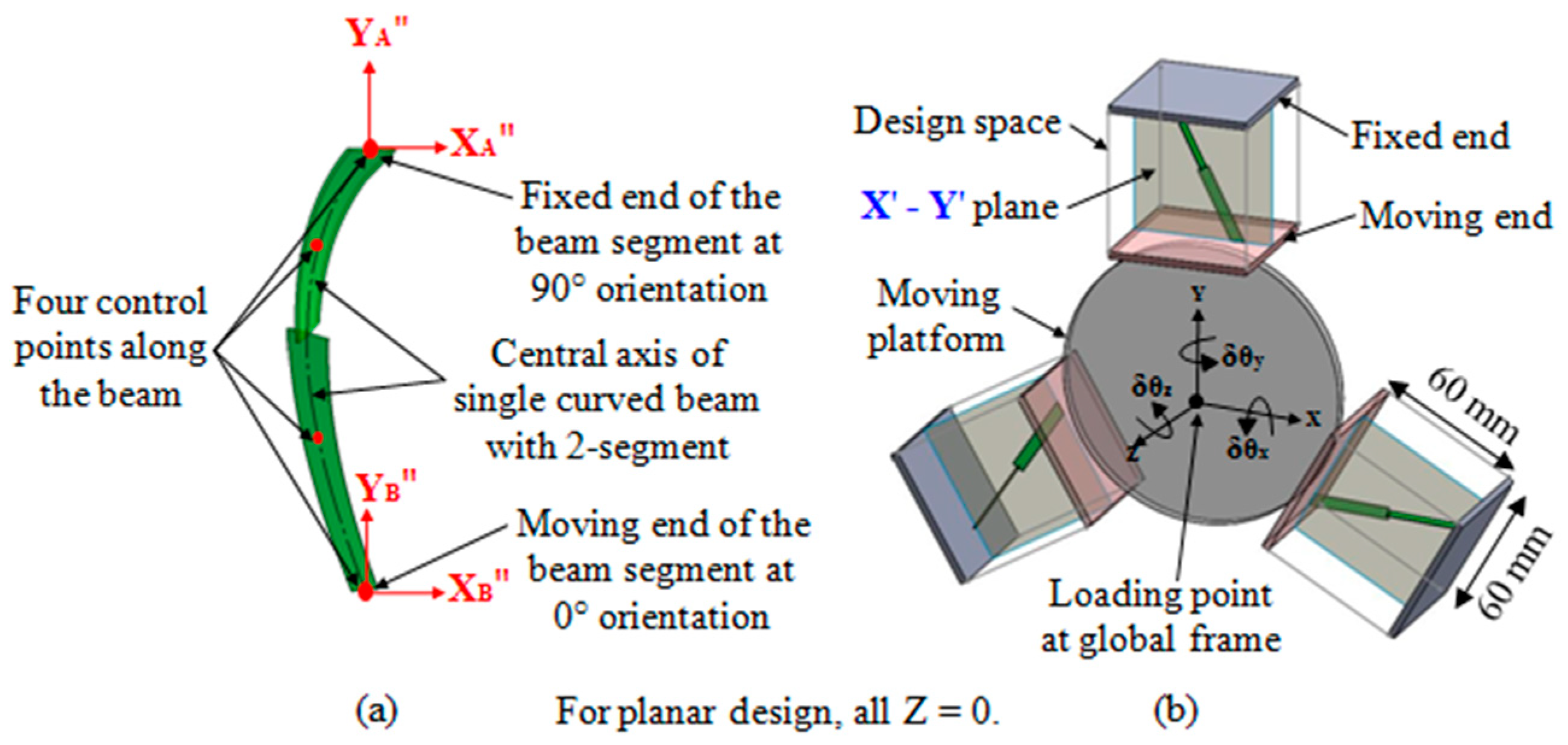
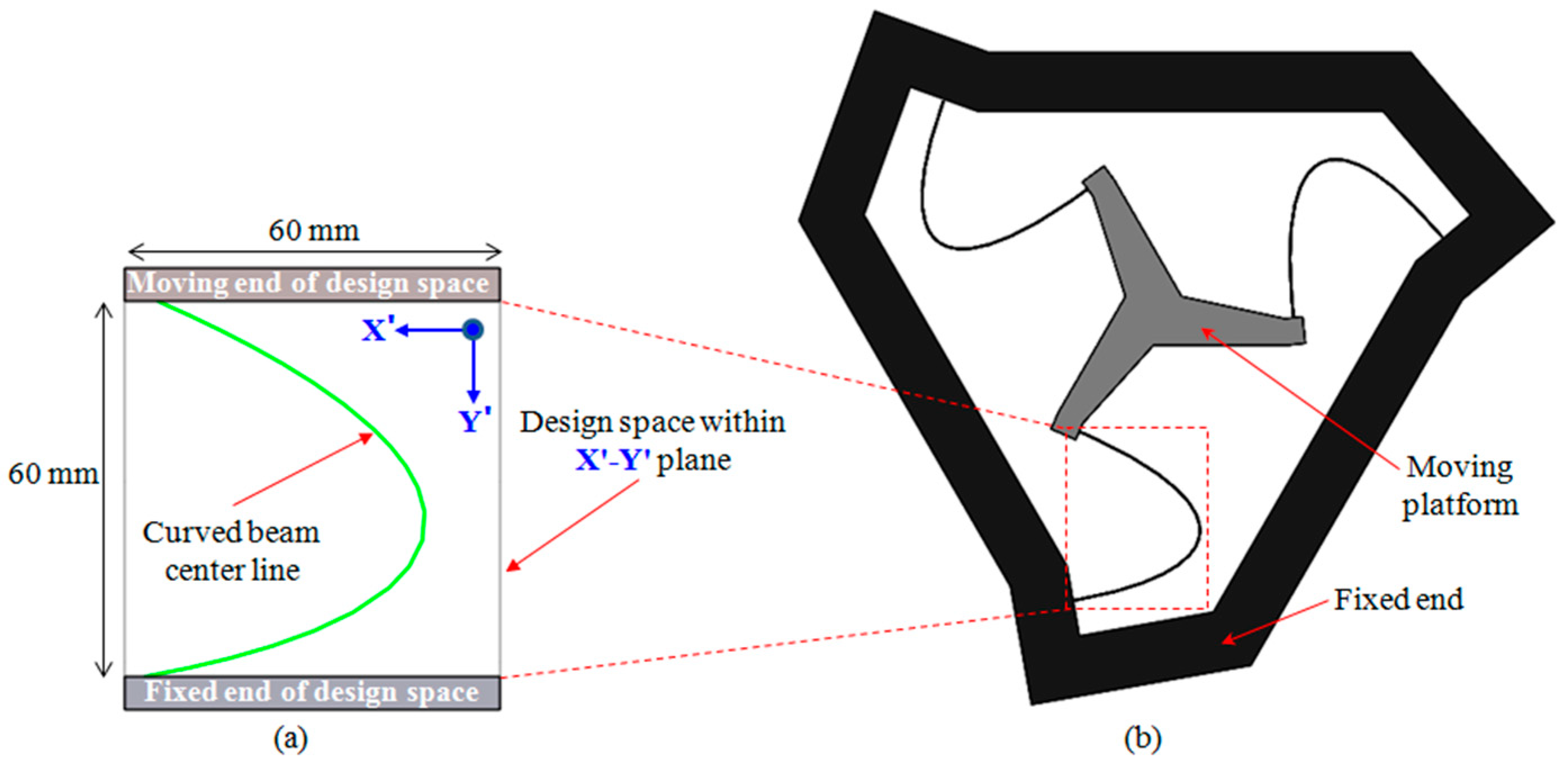
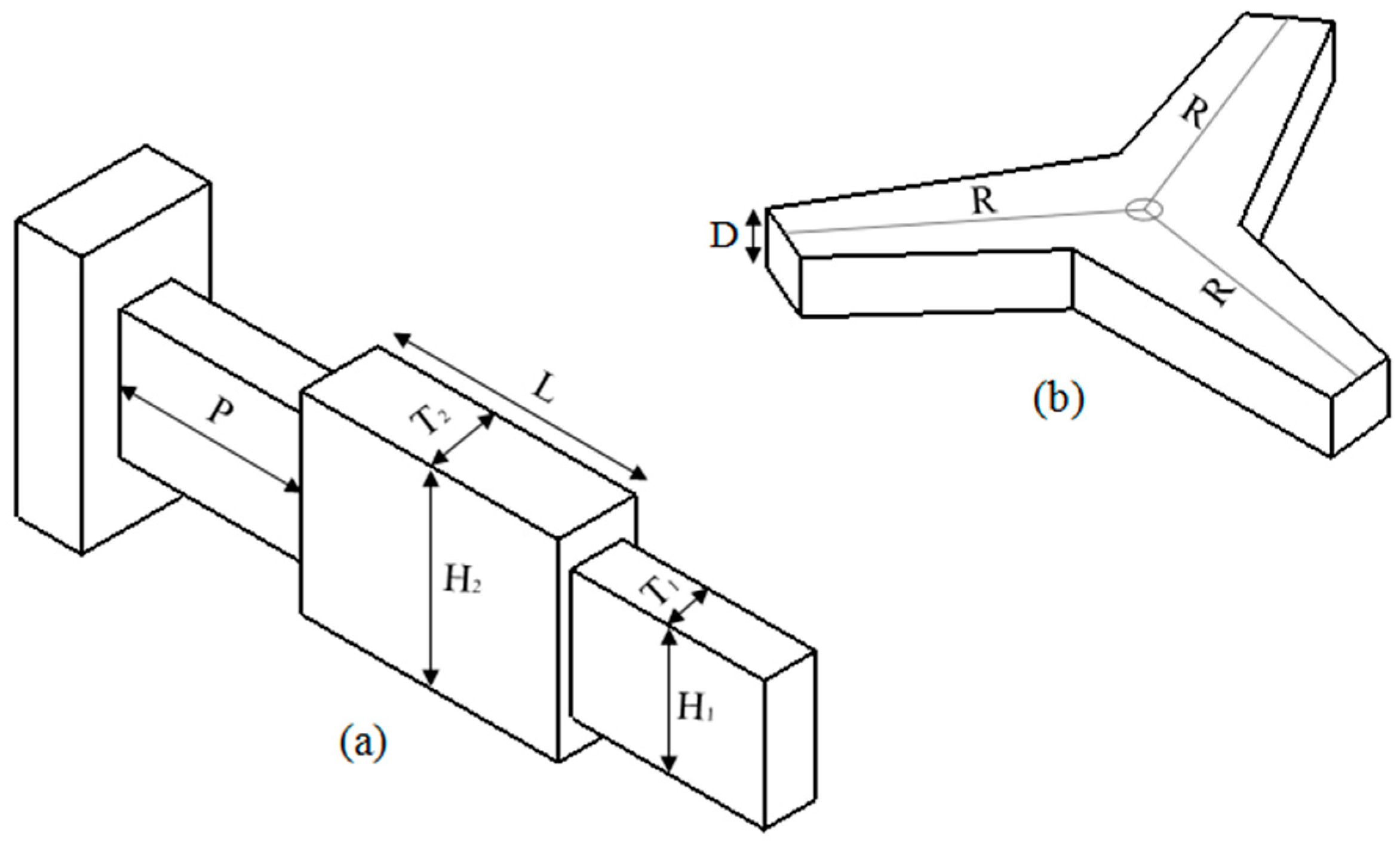
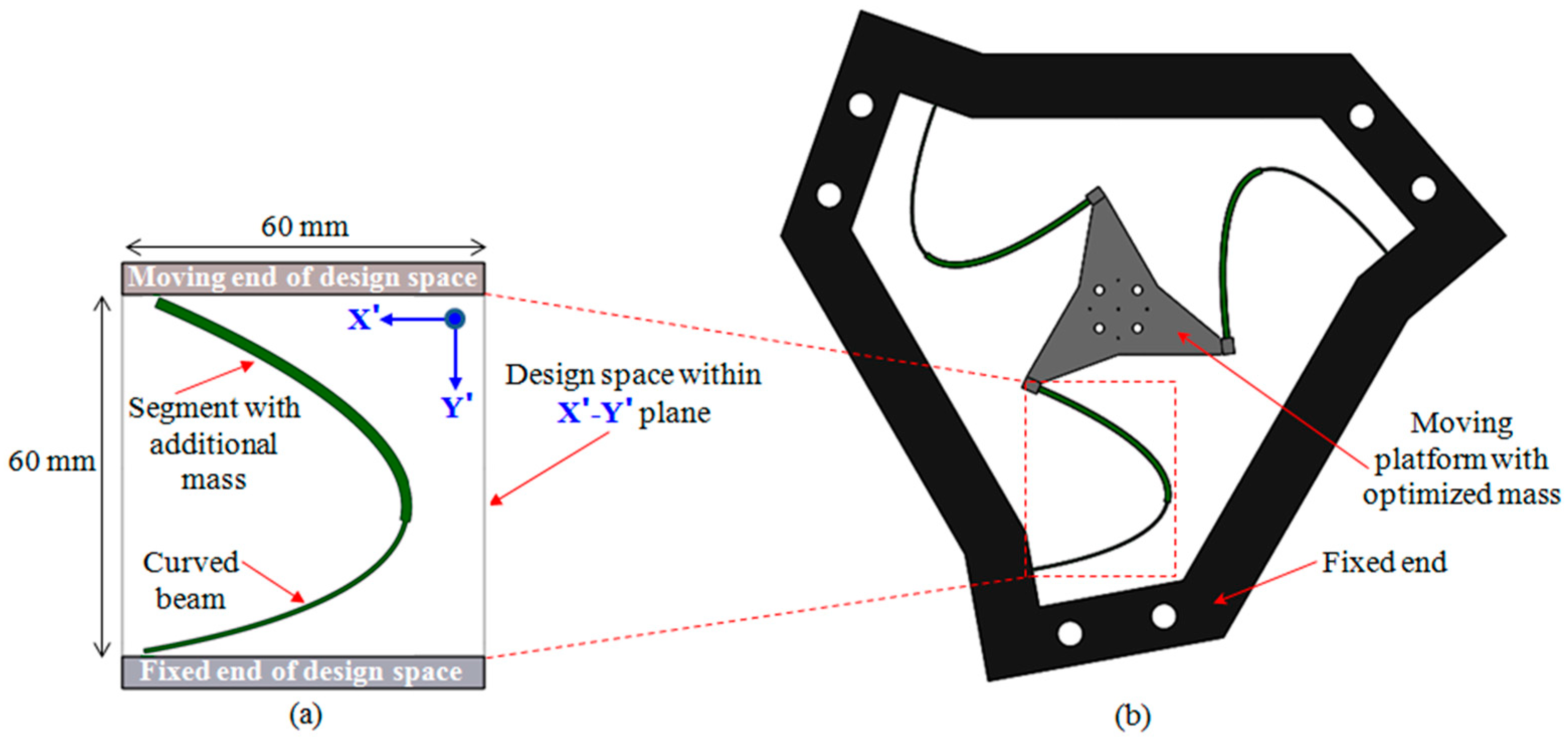
2.1. Synthesis Process

Figure 1 shows the synthesis process of a multiple DoF CPM with motion decoupling. The design specification is first defined, followed by the modeling and optimization of the stiffness property based on the improved beam-based method presented in [24], and then the modeling and optimization of the dynamic property, before the optimal CPM design is obtained. It is worth noting that the main focus and contribution of this paper is the optimization of the dynamic property.
The synthesis process in Figure 1 begins with the specification of necessary parameters for the optimization design. Here, the optimization is separated into two steps, i.e., the stiffness optimization, followed by the dynamic optimization. The stiffness optimization step is performed to determine the optimal structural design of the CPM by defining the geometry of flexures so that the CPM can achieve the highest compliance with the desired DoF. The dynamic optimization is to determine the detailed structures of the CPM in order to obtain targeted resonant frequencies by defining an optimized cross-sectional area of flexures and adding mass at suitable positions. After the two-step optimization process, the optimal design of the CPM with the desired DoF, as well as the desired dynamic behavior and high flexibility, are achieved.

2.2. Stiffness Modeling and Optimization of the 6-DoF CPM

The improved beam-based method reported in [24], used to synthesize a single curved beam with two segments having different beam orientations, is shown in Figure 2a. Figure 2b shows a three-legged configuration for a multiple DoF CPM, which is formed by having three synthesized beams equally distributed around a moving platform. The method is able to synthesize a CPM with motion decoupling characteristics, as well as its multiple resonant modes with unique targeted values.
In this paper, the method used in [24] is employed to synthesize a three-legged 6-DoF CPM with an optimized stiffness property and decoupled motion as a case study. The synthesis results will be generated by a MATLAB program, using the genetic algorithm solver, followed by verification with FEA via ANSYS. The design space of each leg structure is 60 mm × 60 mm, as shown in Figure 2b. Aluminum Alloy 6061 (Young’s modulus of 68.9 GPa, Poisson ratio of 0.33, yield strength of 276 MPa), is selected as the design material.
Referring to the improved beam-based method in [24], the objective function f s , as shown in Equation (1), is employed to perform the stiffness optimization for the 6-DoF CPM, via the genetic algorithm in the MATLAB program. When f s is minimized, the geometry of the CPM that is able to perform the maximum flexibility in desired directions can be achieved. In Equation (1), it can be clearly seen that f s is the product of the six primary stiffness elements of the 6-DoF CPM, and each of the stiffness elements is represented by K i .
minimize   f s = i = 1 6 K i
After the stiffness optimization, the general two-segment curved beam in Figure 2a has evolved to a single vertical curved beam, as illustrated in Figure 3a, to achieve the optimal stiffness property for the entire CPM shown in Figure 3b. The optimized curved beam in a leg structure has a uniform cross-sectional area of 0.4 mm × 3.0 mm. It is also found that the vertical curved beam is lying perpendicularly to the X’-Y’ plane in Figure 3a, which means that the motion decoupling characteristic of the CPM is achieved, as reported in [24]. Figure 3b shows an illustration of how a three-legged 6-DoF CPM is formed by curved beams that are equally distributed around the moving platform; one end of the beam is fixed to the base, and the other end is rigidly connected to the platform. The purpose of this stiffness optimization is to obtain the optimal stiffness property of the CPM only. The optimal size of the curved beam and the platform for the 6-DoF CPM, which will then be optimized using the proposed objective function during the dynamic optimization, is configured to achieve the targeted resonant frequencies of the CPM.
Through the stiffness optimization, the optimized 6-DoF CPM obtained its six resonant frequencies (Hz), represented by F s 6 - DoF , as shown in Equation (2). Note that the detailed calculation of resonant frequencies of the CPM can be found in [24].
F s 6 - DoF = 11.83 11.83 23.86 24.52 68.93 68.93 T
Based on Equation (2), the obtained six resonant frequencies correspond to the resonant modes, from 1 to 6 of the 6-DoF CPM. These six resonant frequencies can be represented by f 1 to f 6 , respectively. It is seen that two pairs of the resonant frequencies, f 1 and f 2 and f 5 and f 6   , are identical due to the property of the three-legged configuration of the CPM. Therefore, it can be highlighted that only four different resonant frequencies should be obtained for the 6-DoF CPM.
In this paper, an objective function is proposed to improve the resonant frequencies obtained in Equation (2) during dynamic optimization. The objective function formulated based on the specific frequency range and targeted ratios has been developed for optimizing dynamic responses of all primary modes of the CPM to targeted frequencies. In the objective function, the first resonant mode, f 1 , is optimized within the frequency range that is specified, and the resonant modes from f 2 to f 6 are optimized to desired frequency values by customizing the targeted ratios from r 2 to r 6 . Referring to the past literature [21,22,23], CPMs with large workspaces can be achieved with a high resonant frequency at approximately 100 Hz in the first resonant mode. Therefore, 100 Hz is used in the first resonant mode f 1 in this work, which defines the specific frequency range to be as follows: f min f 1 f max . The resonant modes from f 2 to f 6 are to be optimized with respect to the targeted ratios, which are recommended as follows: r 2 = 1 , r 3 = 2 , r 4 = 3 , r 5 = r 6 = 5 , respectively, in order to show the effectiveness of the objective function.

2.3. The Novel Objective Function for Optimizing Multiple Resonant Frequencies

The proposed objective function F d shown in Equation (3) has two terms. The first term of the function is used to optimize the first resonant mode f 1 of the CPM within a specific frequency range f min f 1 f max . The second term is used to define the remaining resonant modes f i relative to the first mode f 1 and optimized against the targeted ratios r i . This objective function is capable of customizing and optimizing the multiple resonant modes of any CPM; when F d is minimized, the optimal result is obtained.
minimize F d = f 1 f max + f min f 1 + i = 2 n f i f 1 r i
where:
f 1 is the resonant frequency of the first mode, defined within the range of f min f 1 f max ;
f i is the resonant frequencies corresponding to the i th resonant mode;
r i is the targeted ratio to be customized for f i   , and is defined by r i = f i f 1 ;
n is the number of resonant frequencies to be optimized, corresponding to the DoF of the CPM.
Note that the i value starts from 2, as the first resonant mode is optimized by the first term of the function. n refers to the numbers of primary resonant modes of the system, which is equal to the DoF of the CPM. It is seen that the smaller the value obtained in the second term of the function, the better the optimized results.

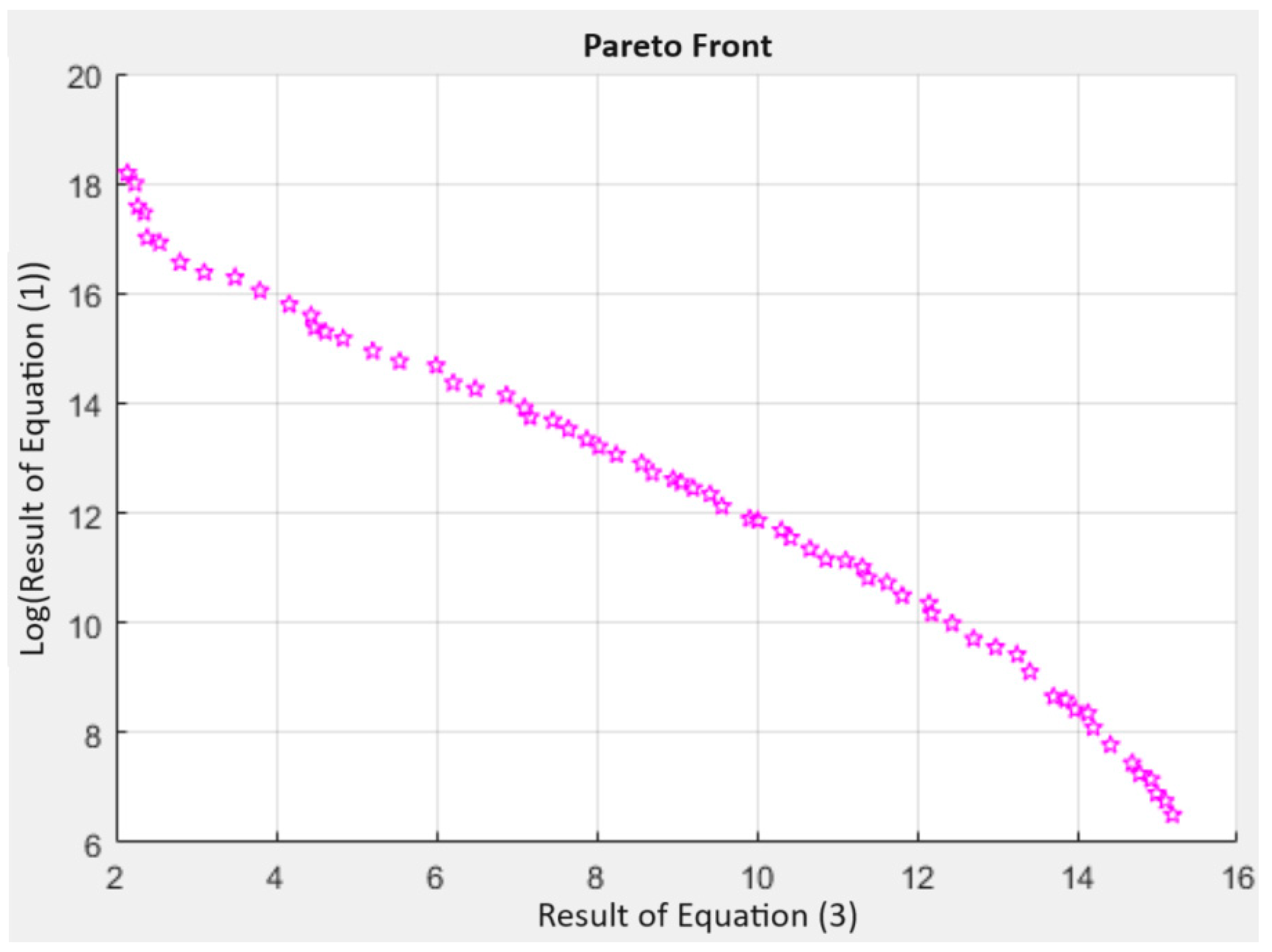
2.4. Dynamic Modeling and Optimization of 6-DoF CPM

The single curved beam obtained from the stiffness optimization, as shown in Figure 3, needs to be further optimized in the dynamic optimization in order to achieve the specified resonant modes. The single curved beam with only two design variables, thickness ( T 1 ) and height ( H 1 ), are not sufficient to create the beam geometry that can achieve the design requirement. Therefore, more design variables on the beam are achieved by introducing an additional mass that is located at a suitable position along the beam during the dynamic optimization. The optimal beam design has eight design variables, as shown in Figure 4. They include the mass of the moving platform (R, D), the beam structure ( T 1 , H 1 ), and the position (P) of the additional mass ( T 2 , H 2 , L). Note that the concept of the eight design variables is from [22].
In the dynamic optimization, the proposed two-term objective function is employed to obtain the optimal design of the 6-DoF CPM. Referring to Equation (3), a frequency range of 95 Hz ≤ f 1 ≤ 105 Hz is selected for optimizing f 1 ; the targeted ratios are customized to be r 2 = 1 , r 3 = 2 , r 4 = 3 , and r 5 = r 6 = 5 , for optimizing the resonant modes f i from f 2 to f 6 , and n = 6 for a 6-DoF CPM. In short, the first resonant mode f 1 of the CPM should be obtained between 95Hz and 105Hz in first term of the function. In the second term of the function, the resonant modes f i are optimized starting from f 2 to f 6 , and the resonant frequencies should be obtained with respect to the customized targeted ratios from r 2 to r 6 . The selected specific frequency range and the customized targeted ratios are sufficiently high and spaced apart for verifying the effectiveness of the proposed objective function in achieving the desired resonant modes of the CPM. It is noted that the targeted frequencies determined by the range of f 1 and the frequency ratios for other resonant modes can be customized depending on specific design requirements.
In this work, both Equation (3) and Equation (1) are solved simultaneously during the multiple objective optimization process to optimize the six primary resonant modes of the 6-DoF CPM targeted values as defined in Equation (3), while keeping its stiffness property as high as possible by Equation (1). The multiple objective optimization problem is carried out using the genetic algorithm and the resulting Pareto Front graph of the dynamic optimization is shown in Figure 5. It is noted that due to the conflicting requirements between the dynamic response represented by the resonant frequencies and the stiffness property of the CPM, the multiple objective optimization has generated a set of optimized results, as illustrated by the points in Figure 5, instead of a unique one. Here, the result with the minimum value of Equation (3) is selected as the final optimized result. This is because the main purpose of the dynamic optimization is to achieve the desired dynamic responses. The stiffness of the CPM increases after the dynamic optimization, which is as expected due to the general relation between stiffness and dynamic properties of a mechanical structure. Note that the flexibility of the CPM in 6-DoF is still good as its stiffness has already been optimized in the stiffness optimization process. This is also the reason why the stiffness and dynamic optimization processes are performed separately. The overall structure of the CPM which is capable of producing the desired DoF must be first defined in the stiffness optimization; the dynamic optimization, which is defined by a multiple objective problem, is then carried out to improve the resonant frequencies to targeted values with some compromise in stiffness, while the desired DoF of the CPM remains the same.
The CPM obtained its optimal size of the leg structure, as shown in Figure 6a. The leg structure consists of a single curved beam, which is made up of two vertical beam segments along the beam on the X’-Y’ plane perpendicularly. The beam segment at the fixed end, without any additional mass, has a cross-sectional area of 0.70 mm × 7.36 mm. The other beam segment at the moving end is with additional mass and has a larger cross-sectional area of 1.75 mm × 10.39 mm. The three-legged 6-DoF CPM, as shown in Figure 6b, is configured by three optimized leg structures, equally distributed around the triangular moving platform. One end of each leg structure is fixed to the base, and the other end is rigidly connected to the moving platform.
From the dynamic optimization, the predicted optimal dynamic resonant frequencies (Hz), F d 6 - DoF of the optimized 6-DoF CPM, consisting of f 1 to f 6 , is shown in Equation (4). Equation (5) shows its 6 × 6 dynamic compliance matrix C d 6 - DoF .
F d   6 - DoF = 96.15 96.15 182.01 302.88 501.45 501.45 T
C d   6 - DoF = diag   [ 1.02   ×   10 4 1.02   ×   10 4 2.97   ×   10 5 1.12   ×   10 2 1.12   ×   10 2 1.57   ×   10 2 ]
From Equation (4), it is seen that the optimized f 1 value of 96.15 Hz is within the specific frequency range of 95 Hz and 105 Hz. The optimized resonant modes of f 2 to f 6 are f 2 = 96.15   Hz , f 3 = 182.01   Hz , f 4 = 302.88   Hz , and f 5 = f 6 = 501.45   Hz . Table 1 shows the comparison of ratios r 2 to r 6 between the obtained ones calculated based on the optimized frequencies against the targeted ratios. It is seen that the obtained ratios are close to the targeted ones with the highest deviation of 5.50%. The small deviations demonstrated that the proposed objective function is effective in optimizing multiple resonant frequencies.
From Equation (5), it is seen that all the off-diagonal elements are zeros in the dynamic compliance matrix. This shows that the optimized 6-DoF CPM is achieved with a fully decoupled motion. This implies that accurate output motions can be generated with no parasitic motions. From the obtained results, the effectiveness of the proposed objective function has been demonstrated.

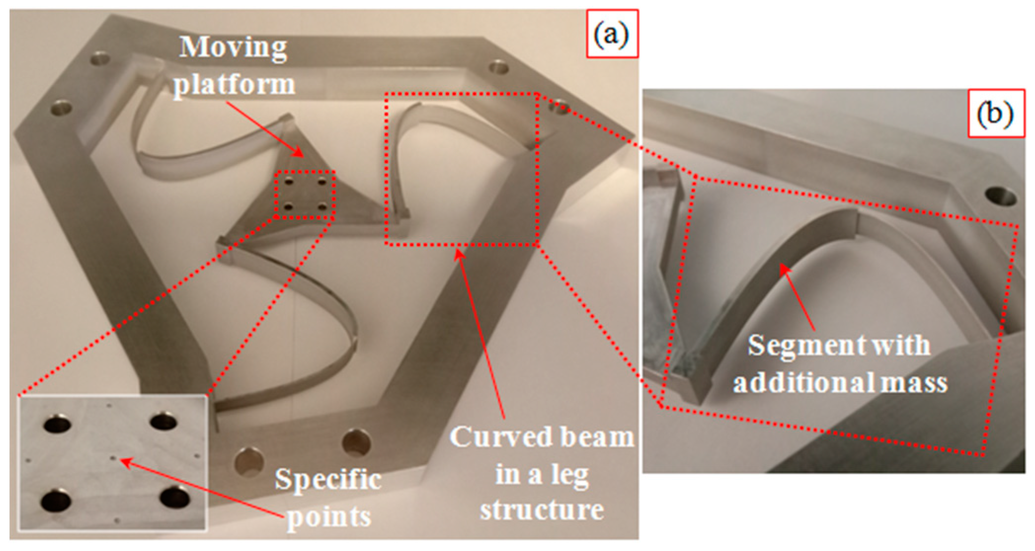
2.5. Summary of Results

FEA is performed via ANSYS Workbench 2023 on a CAD model of the 6-DoF CPM. The resonant frequencies and compliances from FEA are used to verify with those predicted from MATLAB in Equations (4) and (5).
Table 2 shows the comparison of the six resonant modes of the 6-DoF CPM. It is seen that the frequencies between the predicted values and FEA match well and the highest deviation is only 1.33%. The small deviations show the effectiveness of the proposed function and hence the predicted results can be used to compare with the experimental results. Note that the actuating directions of the resonant modes in sequence are also identified from the FEA.
The comparison of the compliances of the 6-DoF CPM is shown in Table 3. Again, there is good agreement, with the highest deviation being 2.55%. Similarly, the predicted compliance results are reliable, and will be used for comparison with experimental results.
Table 4 shows the range of motions in the actuating directions of the 6-DoF CPM obtained from the FEA. It is seen that workspace of the synthesized CPM in terms of translations vary from 4.6 mm to 10.0 mm while the rotations change from 4.4° to 10.8°. This workspace is significantly large compared to the existing six-DoF CPM [23].
Note that the range of the motions will be used as a reference when displacing the moving platform of the CPM during the experimental investigation. Figure 7 shows the vibration modes of the optimized 6-DoF CPM, in sequence. In summary, the small deviations from the comparisons indicated that the optimized 6-DoF CPM is feasible to be prototyped for conducting the experiments.

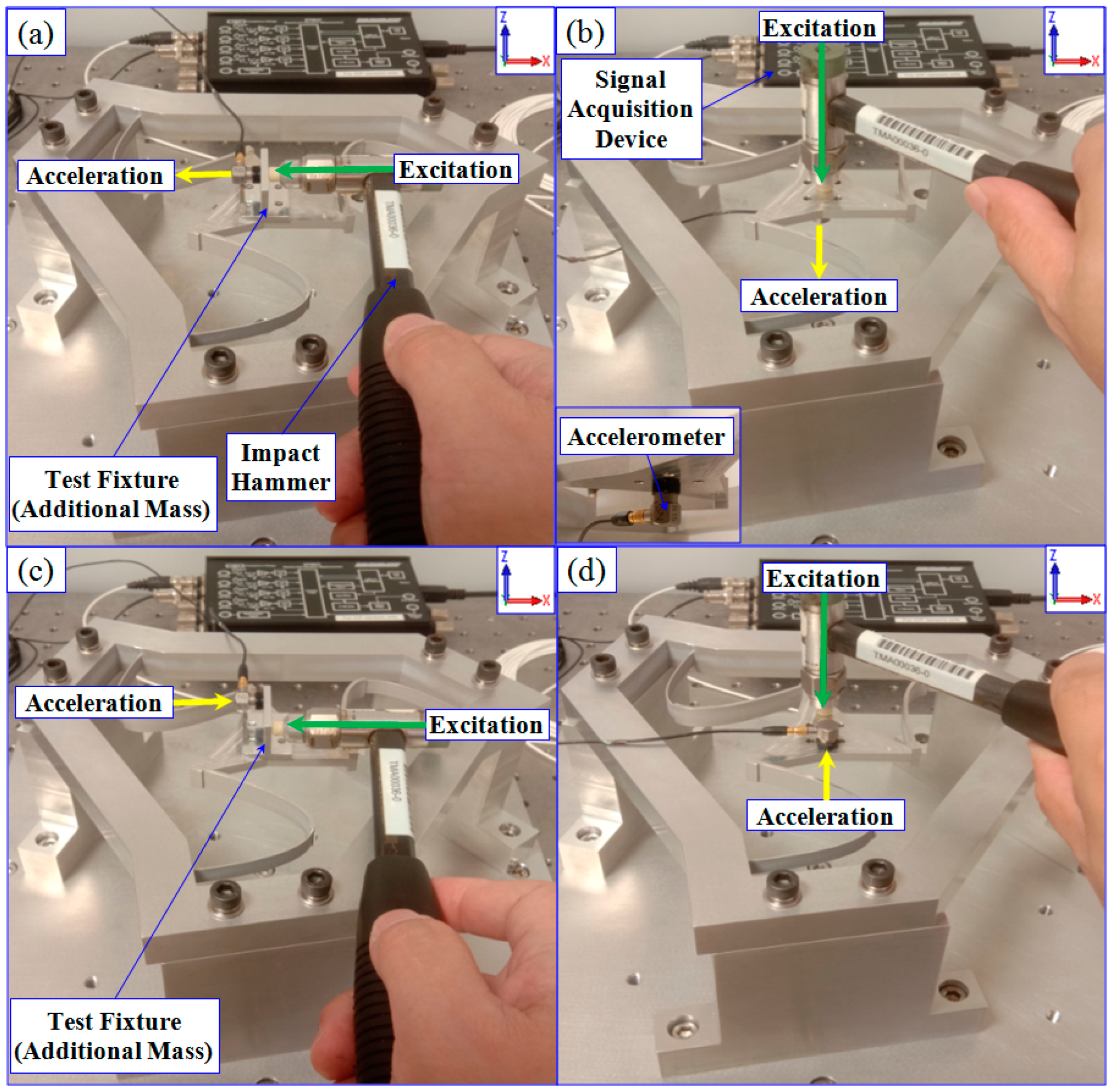
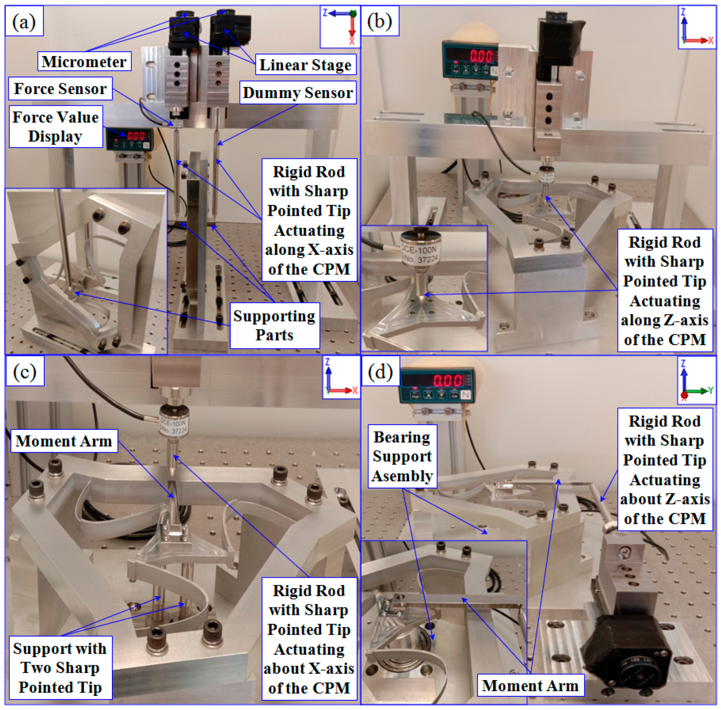
3. Experimental Investigation of the 6-DoF CPM Prototype

Figure 8a shows the 6-DoF CPM prototype, which is monolithically machined by a combination of wire-cut and CNC milling processes; the prototype is made of aluminum alloy 6061, as designed. Figure 8b shows one of the leg structures of the CPM with a curved beam and additional mass, fabricated based on the optimized design, as in Figure 6a. The dynamic experiment is first conducted to verify the effectiveness of the novel objective function, followed by the compliance experiment to verify the results obtained from the synthesis process. Note that in the experiments, each measurement is repeated five times to ensure the repeatability and reliability of the experimental results.

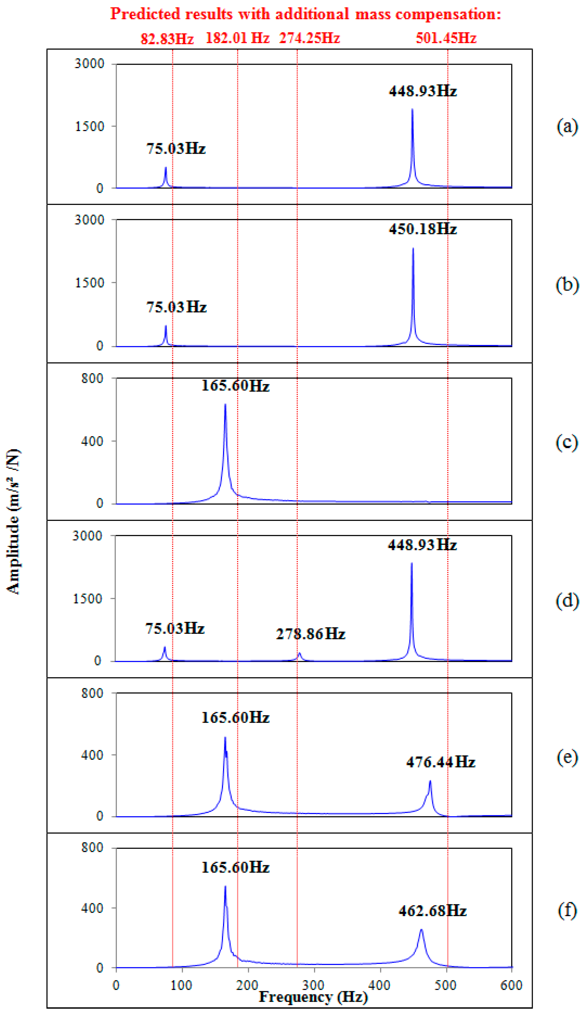
3.1. Dynamic Experiment of the Prototype

Figure 9 shows the experimental setup for evaluating the dynamic responses of the 6-DoF CPM prototype. In the experiment, standard modal analysis equipment is used, consisting of an impact hammer, accelerometer, and signal acquisition device. The input excitation from the impact hammer is sensed by the accelerometer and the signal is transmitted through the signal acquisition device to the frequency response function software for analysis. The analyzed signal will be displayed as a frequency in Hz.
The experimental setups for detecting the dynamic responses along the X-axis and about the Z-axis are shown in Figure 9a and Figure 9c, respectively. Note that for the two setups, a test fixture is mounted on the platform of the prototype. In Figure 9a, an accelerometer is attached on the fixture, opposite to the direction of the input excitation to measure the dynamic response along the X-axis. A similar setup is adopted to measure the direct dynamic response along the Y-axis of the prototype. In Figure 9c, the attached accelerometer on the fixture, receiving the input excitation generated on the opposite direction of the fixture diagonally, measures the dynamic response about the Z-axis of the prototype. It should be highlighted that the additional mass of the test fixture (~11.4 grams) can affect the dynamic behavior of the prototype. The setup to directly evaluate the dynamic response along the Z-axis of the prototype is shown in Figure 9b. Note that the accelerometer, which receives the input excitation, is attached below the moving platform. Figure 9d shows the setup to measure the dynamic response about the X-axis of the prototype. Here, the input excitation is applied vertically downward on the surface of the moving platform, while the accelerometer is attached on the same surface at the other end to measure the acceleration. A similar setup is used to measure the direct dynamic response about the Y-axis of the prototype. FEA is performed to compensate for the additional mass of the test fixture and the compensated resonant frequencies are shown in Table 5. It is noted that the compensated resonant frequencies are reduced compared to the values shown in Table 2 due to the additional mass within the CPM. These compensated frequencies are used as predicted results for further comparisons with the experimental results.
The experimental results of the dynamic responses are shown in Figure 10. Note that the predicted data with the mass compensation presented in Table 5 are marked with vertical red lines, while the blue graphs indicate the measured results from the experiments shown in Figure 9.
From Figure 10a,b,d–f, it is seen that apart from measuring the intended resonant frequency, other resonant frequencies are also captured indirectly. This is due to the directions of the input excitation in the experimental setups, resulting in the capturing of acceleration in other actuating directions. Thus, only those resonant frequencies detected from the direct measurements are used to compare with the predicted results. The comparisons between the experimental and predicted results are presented in Table 6. The highest deviation is found to be 9.42% along the X-axis and Y-axis, and the lowest deviation is found to be 1.68% about the Z-axis. The small deviations suggest that the developed objective function is able to optimize multiple resonant frequencies to targeted values with high accuracy.

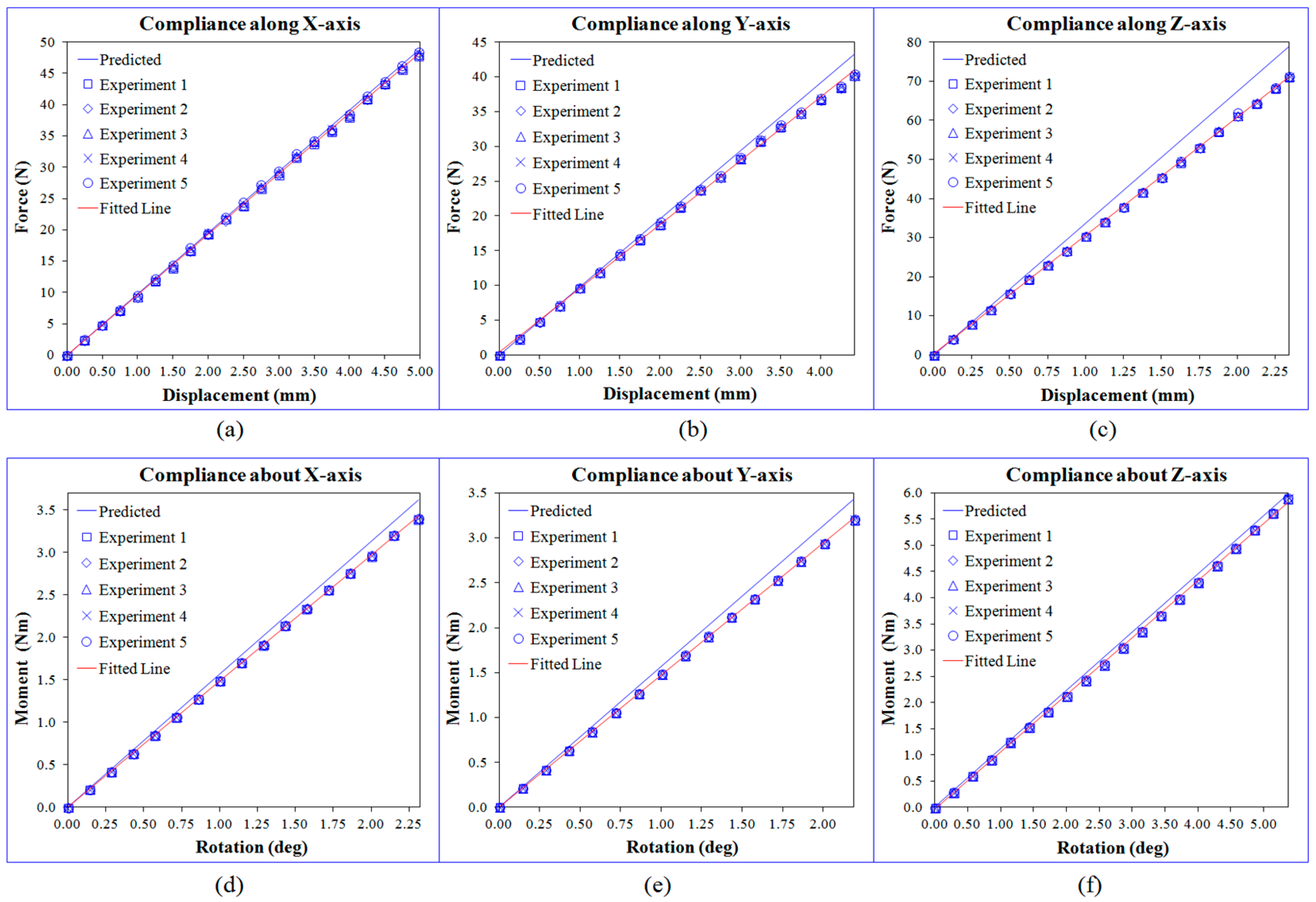
3.2. Compliance Experiment of the Prototype

The experimental setups used to evaluate the compliance property of the 6-DoF CPM prototype are shown in Figure 11. A force sensor (LCM DCE-100N, LCM Systems Ltd., Newport, UK) is employed to measure the actuating force. The sensor is connected to a rigid rod with a pointed tip, secured on the linear stage that will be moved by a micrometer with a resolution of 1.25 μm per step. The micrometer actuates the rod to the specific position on the moving platform, generating the required displacement, and the corresponding actuating force value is shown on a digital display. The displacement and the force values are used to calculate the compliance value of the actuating direction of the prototype.
In Figure 11a, the experimental setup is used to measure the compliance along the X-axis of the prototype. The 6-DoF CPM prototype is mounted vertically with a supporting part being secured on each side of the platform. Both rigid rods contacting on the supporting parts are used to move the platform vertically downward simultaneously by adjusting the micrometers. The force sensor is mounted on one of the micrometers, and so the total actuating force should be twice the displayed value. A similar setup is configured to measure the compliance along the Y-axis of the prototype. Figure 11b shows the setup used to detect the compliance along the Z-axis of the prototype. Similarly, the micrometer is used to move the rigid rod, causing the moving platform to be displaced vertically downward with the corresponding actuating force being measured. Referring to Figure 11c, the setup is used to measure the compliance about the X-axis of the prototype. Two rods with pointed tips are placed below the platform, ensuring that a pure rotation can be generated about the X-axis. A similar setup is configured to measure the compliance about the Y-axis of the prototype. Figure 11d shows the setup used to measure the compliance about the Z-axis of the prototype. A bearing support assembly is attached below the moving platform, ensuring that a pure rotation can be generated about the Z-axis. A moment arm is fixed to the moving platform and the actuating force is applied to this moment arm to generate the desired rotation about the Z-axis.
The results obtained from the compliance experiments are plotted in Figure 12. Note that in the experiments, each measurement is repeated five times to ensure the repeatability and reliability of the experimental results. From Figure 12, it is seen that all the compliances exhibit a linear relationship in the six actuating directions. This shows that the prototype is able to function linearly throughout its entire range of motions. In addition, the experimental results versus the predicted values are shown to be with low deviations. Table 7 shows the comparison of the compliances between the experimental results and the predicted ones. The highest deviation is found to be 10.77% along the Z-axis, and the lowest one is found to be 0.98% about the X-axis. It is noteworthy that the curved shape and thin cross-section throughout the beam length are difficult to fabricate with high accuracy; they can be considered as the uncertainties that could affect the stiffness performance of the CPM.

4. Discussion of the Results

Referring to Table 1, it is seen that the ratios of the resonant frequencies with the highest deviation between the obtained results and the targeted ones is 5.50%. Similarly, the highest deviations between the FEA results and the predicted ones for resonant frequencies and compliances are found to be 1.33% and 2.55%, respectively (see Table 2 and Table 3). These small deviations show that the predicted results are reliable and can be used to compare with the experimental results. Moreover, all the off-diagonal elements of the dynamic compliance matrix in Equation (5) are zeros, implying that the optimized 6-DoF CPM has decoupled motion characteristics. Hence, accurate output motions can be generated with no parasitic motions. From the obtained results, the effectiveness of the proposed novel objective function to optimize multiple resonant frequencies of the CPM has been demonstrated.
The six resonant frequencies obtained experimentally are 75.03 Hz, 75.03 Hz, 165.60 Hz, 278.86 Hz, 476.44 Hz, and 462.68 Hz. The ranges of motions are found to be 10 mm × 8.8 mm × 4.6 mm along the three translations (X-Y-Z), and 4.6° × 4.4° × 10.8° for the three rotations ( θ X - θ Y - θ Z ). The highest deviation between the experimental results and predictions among the six resonant modes is found to be 9.42%, while the highest deviation in the compliances is 10.77%. The high compliance deviation in the translation Z-axis of the prototype could be due to the manufacturing errors during the wire cut and CNC machining processes. These errors are difficult to account for.
In this work, the desired multiple resonant modes of a 6-DoF CPM are optimized by the proposed objective function with a specified frequency range and targeted ratios. The optimized 6-DoF CPM with a single curved beam is also simpler than the 6-DoF CPM with a pair of curved beams presented in [23]. Note that the proposed objective function enables the multiple resonant modes of any CPM to be customized through the specification of a frequency range and targeted ratios. This capability is a significant improvement over the dynamic optimization techniques presented in [22,23], which can only optimize the first resonant mode of the CPM, and those in [24], which use unique values to optimize the multiple resonant modes of the CPM. In addition, the proposed function can also be used to improve the resonant frequencies of existing compliant mechanisms [9,10,11,12,13,14,15,16,17,18,19,20] that have no mention of the desired values for their dynamic responses. Importantly, this objective function can be applied to any design methodology to synthesize the desired dynamic behaviors of any multi-DoF CPM or any compliant structure.

5. Conclusion

In this paper, a novel objective function capable of optimizing the dynamic responses of a compliant parallel mechanism (CPM), in terms of its multiple primary resonant modes, was proposed. The function was formulated based on a specific frequency range and targeted ratios. To show the effectiveness of the proposed function, a 6-DoF CPM with decoupled motion was numerically optimized, monolithically prototyped, and experimentally investigated and verified, in terms of its mechanical properties. The experimental results showed that the proposed objective function is capable of optimizing the six resonant modes within the desired frequency range and the targeted ratios. The highest deviation between the experimental results and predictions among the six resonant modes was found to be 9.42%, while the highest deviation in the compliances was 10.77%. The range of motions were found to be 10.0 mm in the translations, and 10.8° in the rotations.
In summary, it has been shown that the proposed objective function is able to optimize the resonant frequencies of the 6-DoF CPM effectively. The introduction of a specific frequency range and targeted ratios in the objective function allows for the customization of multiple resonant frequencies of the CPM for specific purposes. This is a contribution to the research field of compliant mechanisms. In addition, we will continue to explore other techniques which are able to perform accurate control in the optimization process for multiple resonant frequencies of CPMs.

Author Contributions

Conceptualization, methodology, software, validation, formal analysis, investigation, visualization, writing—original draft preparation, V.L.; writing—review and editing, supervision, S.H.Y. and M.T.P. All authors have read and agreed to the published version of the manuscript.

Funding

This research received no external funding.

Data Availability Statement

The data presented in this study are available on request from the corresponding author due to privacy reasons..

Acknowledgments

This research work was supported by the School of Mechanical and Aerospace Engineering (MAE), Nanyang Technological University (NTU) in Singapore. We thank the support of the technical staff in the Robotics Research Laboratory and the Mechanics of Machines Laboratory. Furthermore, we would like to acknowledge Ho Chi Minh City University of Technology (HCMUT) VNU-HCM for supporting this study.

Conflicts of Interest

The authors declare no conflicts of interest.

References

  1. Wu, X.-C.; Lu, Y.; Duan, X.-C.; Zhang, D.; Deng, W.-Y. Design and DOF Analysis of a Novel Compliant Parallel Mechanism for Large Load. Sensors 2019, 19, 828. [Google Scholar] [CrossRef]
  2. Paniselvam, V.; Tan, N.Y.J.; Anantharajan, S.K. A Review on the Design and Applications of Compliant Mechanism-Based Fast-Tool Servos for Ultraprecision Machining. Machines 2023, 11, 450. [Google Scholar] [CrossRef]
  3. Zhan, W.-H.; He, X.-H.; Yang, J.-M.; Lai, J.-H.; Zhu, D.-C. Optimal design method for 3-DOF planar compliant mechanisms based on mapping matrix constraints. Structures 2020, 26, 1–5. [Google Scholar] [CrossRef]
  4. Thomas, T.L.; Venkiteswaran, V.K.; Anathasureh, G.K.; Misra, S. Surgical Applications of Compliant Mechanisms—A Review. J. Mech. Robot. 2021, 13, 020801. [Google Scholar] [CrossRef]
  5. Ling, M.-X.; Cao, J.-Y.; Howell, L.L.; Zeng, M.-H. Kinetostatic modeling of complex compliant mechanisms with serial-parallel substructures: A semi-analytical matrix displacement method. Mech. Mach. Theory 2018, 125, 169–184. [Google Scholar] [CrossRef]
  6. Zhang, Y.; Su, H.-J.; Liao, Q.-Z. Mobility criteria of compliant mechanisms based on decomposition of compliance matrices. Mech. Mach. Theory 2014, 79, 80–93. [Google Scholar] [CrossRef]
  7. Teo, T.J.; Yang, G.-L.; Chen, I.-M. Compliant Manipulators. In Handbook of Manufacturing Engineering and Technology; Springer: London, UK, 2014; pp. 1–63. [Google Scholar]
  8. Wang, R.-Z.; Zhang, X.-M. Optimal design of a planar parallel 3-DOF nanopositioner with multi-objective. Mech. Mach. Theory 2017, 112, 61–83. [Google Scholar] [CrossRef]
  9. Zhang, X.-Z.; Xu, Q.-S. Design and Analysis of a Compound Constant-Force Mechanism for Compliant Gripper. In Proceedings of the 2018 International Conference on Manipulation, Automation and Robotics at Small Scales (MARSS), Nagoya, Japan, 4–8 July 2018. [Google Scholar]
  10. Ai, W.-J.; Xu, Q.-S. New Structural Design of a Compliant Gripper Based on the Scott-Russell Mechanism. Int. J. Adv. Robot. Syst. 2014, 11, 192. [Google Scholar] [CrossRef]
  11. Zhu, W.-L.; Zhu, Z.-W.; Guo, P.; Ju, B.-F. A novel hybrid actuation mechanism based XY nanopositioning stage with totally decoupled kinematics. Mech. Syst. Signal Process 2018, 99, 747–759. [Google Scholar] [CrossRef]
  12. Li, Y.-M.; Xiao, S.-L.; Xi, L.-Q.; Wu, Z.-G. Design, Modeling, Control and Experiment for a 2-DOF Compliant Micro-Motion Stage. Int. J. Precis. Eng. Manuf. 2014, 15, 735–744. [Google Scholar] [CrossRef]
  13. Yang, B.; Zhang, C. Design and Analysis of a 3-DOF Planar Flexure-based Parallel Mechanism with Large Motion Range. In Proceedings of the IEEE International Conference on Robotics and Biometrics, Kuala Lumpur, Malaysia, 12–15 December 2018. [Google Scholar]
  14. Bhagat, U.; Shirinzadeh, B.; Clark, L.; Chea, P.; Qin, Y.-D.; Tian, Y.-L.; Zhang, D.-W. Design and analysis of a novel flexure-based 3-DOF mechanism. Mech. Mach. Theory 2014, 74, 173–187. [Google Scholar] [CrossRef]
  15. Chen, X.-G.; Li, Y.-M.; Xie, Y.-L.; Wang, R.-B. Design and analysis of new ultra compact decoupled XYZθ stage to achieve large-scale high precision motion. Mech. Mach. Theory 2022, 167, 104527. [Google Scholar] [CrossRef]
  16. Ahn, D.-H.; Choi, Y.-M.; Jeong, J.-H. Design of a four-degree-of-freedom nano positioner utilizing electromagnetic actuators and flexure mechanisms. Rev. Sci. Instrum. 2015, 86, 035101. [Google Scholar] [CrossRef] [PubMed]
  17. Shen, Y.-P.; Luo, X.; Wang, S.-L.; Li, X.-J. Dynamic Analysis of a 5-DOF Flexure-Based Nanopositioning Stage. Math. Probl. Eng. 2019, 2019, 8501583. [Google Scholar] [CrossRef]
  18. Zhang, D.; Gao, Z. Performance analysis and optimization of a five-degrees-of-freedom compliant hybrid parallel micromanipulator. Robot. Comput. Integr. Manuf. 2015, 34, 20–29. [Google Scholar] [CrossRef]
  19. Lin, C.; Zheng, S.; Li, P.-Y.; Jiang, M.-D. Kinetostatic analysis of 6-DoF compliant platform with a multi-stage condensed modeling method. Microsyst. Technol. 2021, 27, 2153–2166. [Google Scholar] [CrossRef]
  20. Ghafarian, M.; Shrinzadesh, B.; Das, T.K.; Al-Jodah, A.; Wei, W.-C. Design of a novel parallel monolithic 6-DOF compliant micromanipulation mechanism. In Proceedings of the IEEE/ASME International Conference on AIM, Auckland, New Zealand, 9–12 July 2018. [Google Scholar]
  21. Ghafarian, M.; Shirinzadeh, B.; Al-Jodah, A.; Das, T.K.; Pinskier, J. FEA-based optimization of a complete structure of a monolithic z/tip/tilt micromanipulator. J. Micro-Bio Robot. 2020, 16, 93–110. [Google Scholar] [CrossRef]
  22. Pham, M.T.; Teo, T.J.; Yeo, S.H. Synthesis of multiple degrees-of-freedom spatial-motion compliant parallel mechanisms with desired stiffness and dynamics characteristics. Precis. Eng. 2017, 47, 131–139. [Google Scholar] [CrossRef]
  23. Pham, M.T.; Yeo, S.H.; Teo, T.J.; Wang, P.; Nai, M.L.S. A Decoupled 6-DOF Compliant Parallel Mechanism with Optimized Dynamic Characteristics Using Cellular Structure. Machines 2021, 9, 5. [Google Scholar] [CrossRef]
  24. Low, V.; Yeo, S.H.; Pham, M.T. Synthesis of Compliant Parallel Mechanisms Using an Improved Beam-Based Method with the Optimization of Multiple Resonant Modes. Machines 2023, 11, 731. [Google Scholar] [CrossRef]
Figure 1. The synthesis process.
Machines 12 00585 g001
Figure 2. (a) Single curved beam with two segments and its orientations at 0° or 90°; (b) three-legged configuration of CPM.
Machines 12 00585 g002
Figure 3. (a) The single curved beam in a leg structure; (b) the three-legged 6-DoF CPM.
Machines 12 00585 g003
Figure 4. The eight design variables representation. (a) The curved beam; (b) the moving platform.
Machines 12 00585 g004
Figure 5. Pareto Front chart of the dynamic optimization.
Machines 12 00585 g005
Figure 6. (a) The optimized leg structure; (b) the three-legged 6-DoF CPM.
Machines 12 00585 g006
Figure 7. The vibration modes of the synthesized 6-DoF CPM: (a) along X-axis; (b) along Y-axis; (c) along Z-axis; (d) about Z-axis; (e) about X-axis; and (f) about Y-axis.
Machines 12 00585 g007
Figure 8. (a) The 6-DoF CPM prototype; (b) the beam segment with additional mass.
Machines 12 00585 g008
Figure 9. Experimental setup of dynamic response at: (a) along X-axis; (b) along Z-axis; (c) about Z-axis; and (d) about X-axis.
Machines 12 00585 g009
Figure 10. Experimental resonant frequencies at (a) along X-axis; (b) along Y-axis; (c) along Z-axis; (d) about Z-axis; (e) about X-axis; and (f) about Y-axis.
Machines 12 00585 g010
Figure 11. Experimental setup of compliance at (a) along X-axis; (b) along Z-axis; (c) about X-axis; and (d) about Z-axis.
Machines 12 00585 g011
Figure 12. Experimental result plotted against the predicted and FEA at (a) along X-axis; (b) along Y-axis; (c) along Z-axis; (d) about X-axis; (e) about Y-axis; and (f) about Z-axis.
Machines 12 00585 g012
Table 1. Comparison of ratios: targeted versus obtained.
Resonant ModeTargeted RatioObtained RatioDeviation (%)
r 2 110
r 3 21.895.50
r 4 33.155.00
r 5 55.224.40
r 6 55.224.40
Table 2. Comparison of the resonant frequencies: FEA versus predicted values.
Actuating
Direction
Predicted
Resonant Frequency (Hz)
FEA
Resonant Frequency (Hz)
Deviation
(%)
Along X—axis96.1595.310.87
Along Y—axis96.1595.330.85
Along Z—axis182.01179.751.24
About Z—axis302.88298.861.33
About X—axis501.45496.890.91
About Y—axis501.45497.070.87
Table 3. Comparison of the compliances: FEA versus predicted values.
Actuating
Direction
Predicted Compliance
(m/N) or (rad/Nm)
FEA Compliance
(m/N) or (rad/Nm)
Deviation
(%)
Along X—axis 1.02 × 10 4 1.04 × 10 4 1.96
Along Y—axis 1.02 × 10 4 1.04 × 10 4 1.96
Along Z—axis 2.97 × 10 5 3.01 × 10 5 1.35
About X—axis 1.12 × 10 2 1.14 × 10 2 1.79
About Y—axis 1.12 × 10 2 1.14 × 10 2 1.79
About Z—axis 1.57 × 10 2 1.61 × 10 2 2.55
Table 4. Range of motions of the 6-DoF CPM verified via FEA.
Actuating
Direction
Along X-AxisAlong Y-AxisAlong Z-AxisAbout X-AxisAbout Y-AxisAbout Z-Axis
Full Range of Motion
(±Range of Motion)
10.0 mm
(±5.0 mm)
8.8 mm
(±4.4 mm)
4.6 mm
(±2.3 mm)
4.6°
(±2.3°)
4.4°
(±2.2°)
10.8°
(±5.4°)
Table 5. Predicted resonant frequencies with mass compensation.
Actuating
Direction
Along X-AxisAlong Y-AxisAlong Z-AxisAbout Z-AxisAbout X-AxisAbout Y-Axis
Resonant
Frequency (Hz)
82.8382.83182.01274.25501.45501.45
Table 6. Comparison of the resonant frequencies: experimental versus predicted values.
Actuating
Direction
Predicted
Resonant Frequency (Hz)
Experimental
Resonant Frequency (Hz)
Deviation
(%)
Along X—axis82.8375.039.42
Along Y—axis82.8375.039.42
Along Z—axis182.01165.609.02
About Z—axis274.25278.861.68
About X—axis501.45476.444.99
About Y—axis501.45462.687.73
Table 7. Comparison of the compliances: experimental versus predicted values.
Actuating
Direction
Predicted Compliance
(m/N) or (rad/Nm)
Experimental Compliance
(m/N) or (rad/Nm)
Deviation
(%)
Along X—axis 1.02 × 10 4 1.03 × 10 4 0.98
Along Y—axis 1.02 × 10 4 1.08 × 10 4 5.88
Along Z—axis 2.97 × 10 5 3.29 × 10 5 10.77
About X—axis 1.12 × 10 2 1.18 × 10 2 5.36
About Y—axis 1.12 × 10 2 1.19 × 10 2 6.25
About Z—axis 1.57 × 10 2 1.61 × 10 2 2.55
Disclaimer/Publisher’s Note: The statements, opinions and data contained in all publications are solely those of the individual author(s) and contributor(s) and not of MDPI and/or the editor(s). MDPI and/or the editor(s) disclaim responsibility for any injury to people or property resulting from any ideas, methods, instructions or products referred to in the content.

