Review

Power Transmission Mechanism and Tribological Performance of Modern Bicycle Drivetrains—A Review

by
Yook Wah Liew
1,
Owen Matthews
2,
Dzung Viet Dao
1 and
Huaizhong Li
1,*
1
School of Engineering and Built Environment, Gold Coast Campus, Griffith University, Southport, QLD 4222, Australia
2
Ride Mechanic Pty Ltd., P.O. Box 5191, Daisy Hill, QLD 4127, Australia
*
Author to whom correspondence should be addressed.
Machines 2025, 13(1), 66; https://doi.org/10.3390/machines13010066
Submission received: 16 December 2024 / Revised: 14 January 2025 / Accepted: 15 January 2025 / Published: 17 January 2025
(This article belongs to the Special Issue Advancements in Mechanical Power Transmission and Its Elements)

Abstract

:
Bicycles are one of the most sustainable forms of transportation and sports available today, known for their environmental friendliness, cost-effectiveness, lightweight design, compactness, and health benefits. The efficiency and power transmission of bicycle drivetrains have emerged as crucial concerns for engineers, bicycle manufacturers, and both professional and amateur cyclists. However, research and publications related to bicycle drivetrain systems and their tribological performance are notably limited. There is a lack of systematic reviews on technological progress and recent research works in this field. This paper aims to redress this imbalance by presenting a comprehensive literature review of power transmission and tribology in bicycle drivetrains through assessing an extensive body of theoretical and practical work encompassing bicycle drivetrains and roller chain drive mechanisms and performance. This review comprises an exploration of bicycle drivetrain mechanisms and components, an examination of subjects related to power transmission mechanics and efficiency, and a thorough analysis of tribological factors in bicycle drivetrains, including friction, wear, and lubrication. A particular focus has been put on the performance of roller chain drives. This review consolidates research findings related to power transmission within the bicycle drivetrain systems and outlines some future perspectives in relevant research. Through this review, we aim to shed light on the existing knowledge gaps within bicycle drivetrain research and offer constructive recommendations for advancements in this field.

1. Introduction

Bicycles, powered by human energy, have undergone substantial evolution since their invention in the early 19th century, and they have become a popular form of transportation, recreation, and sports around the world. The utilisation of bicycles offers numerous advantages, such being environmentally friendly and pollution-free, good for the rider’s health, low cost, lightweight, and enjoyable. A recent study found that cycling can be a viable transport option for short- and medium-length trips for many individuals and trip purposes in a modern city [1], which is considered the most successful option to relieve traffic jams [2]. Chen et al. [3] complied a global dataset for bicycle ownership and use from 1962 to 2015 and reported that the global production of bicycles had a compound annual growth rate of 3.4% in this period, increasing from 20.7 million units in 1962 to 123.3 million units in 2015. This is higher than that of global car production (3.0% from 14.0 million units to 68.6 million units) in the same period [3]. The aggregated amount of global bicycle production in this period is 4.65 billion units, which is 2.4 times the aggregated amount of global car production [3]. The global production of bicycles and e-bikes reached 193 million units in 2021, growing 11 percent from the previous year [4]. In comparison, the production of global motor vehicles was at around 85.4 million units in 2022, denoting an increase of 5.7% from 2021. According to a market analysis report by the Grand View Research organisation, the global bicycle market size was valued at USD 64,625.7 million in 2022. The compound annual growth rate from 2023 to 2030 was expected to be at 9.7% [5].
Various types of bicycles have been invented, including mountain bikes, road bikes, hybrid bikes, cruise bikes, track bikes, etc. [6]. The advent of electric bicycles (e-bikes) [7], the establishment of public bike-sharing systems [8], and the growing interest in cycling activities have further propelled the popularity of bicycles, leading to an increase in the number of cyclists [9]. In addition to being a popular recreational activity, cycling can also be pursued as a competitive sport. Bicycle races are popular worldwide, which include several categories such as road bicycle racing, mountain bike racing, and track cycling. Bicycles have great potential to contribute to a more sustainable, healthy, and equitable society.
Despite their great economic and social significance, research and publications related to bicycles, especially their drivetrain systems, have been notably limited. It has been reported that cycling races are sometimes won by time differences of fractions of a second or a few centimetres [10]. Transmission inefficiency due to chain and bearing losses can be a critical factor contributing to the loss of a competition [6]. Therefore, the design and manufacture of bicycles with a higher power efficiency are becoming increasingly of interest. This paper aims to redress this imbalance by undertaking a comprehensive literature review of the bicycle drivetrain system, with a specific focus on its power transmission mechanisms and tribological performance. This emphasis is driven by the paramount importance of power transmission to riders, bicycle designers, and engineers, coupled with the effectiveness of tribology as a tool in comprehending and enhancing the vehicle’s drivetrain system [11]. It has been reported that competitive track cycling races are won by milliseconds [12], and the power transmission efficiency is an important factor in performance. To ensure that this review was able to capture all the significant contributions in bicycle drivetrain power transmission and tribology, a systematic quantitative literature review technique was used [13], which is a derivation of the classic systematic literature review approach.
This paper is structured as follows. Section 2 introduces the various mechanisms and fundamental components found in bicycle drivetrain systems. Section 3 explores the power transmission mechanics and efficiency within the drivetrain, covering power loss mechanisms, factors influencing efficiency, the contact mechanics between chain and sprockets, load assessment, and the kinematic and dynamic behaviour of the system. Section 4 delves into the tribological behaviour of bicycle drivetrain systems, with a focus on wear and lubrication. Conclusions are provided in the final section, with current trends and future perspectives in bicycle drivetrain research outlined.

2. Mechanisms and Components in Bicycle Drivetrains

The drivetrain system of bicycles transfers power from the rider’s pedals to the rear wheel, propelling the bike forward. Traditionally, single-speed drivetrains have been widely used in classic, casual, and track bikes. As shown in Figure 1a, this type of drivetrain comprises a single chainring and a single cog connected by a chain, thus providing only a fixed gear ratio [14]. Single-speed drivetrains offer the advantages of affordability, reduced weight, minimal maintenance, and overall reliability. However, they do not allow for gear changes and thus multispeed ratios, which can be limiting in certain situations such as tackling steep hills [15].
In contrast, most modern bicycles more often employ multispeed drivetrains that enable riders to shift between different gear ratios and adjust their pedalling effort to various road conditions and personal fitness levels [16]. Multispeed drivetrains consist of various types of chains, sprockets, and additional gear-shifting mechanisms. They can be further classified into 1× drivetrains and 2/3× drivetrains based on the number of front sprockets or chainrings present, as in Figure 1b,c. A 1× drivetrain consists of a single front chainring/sprocket and a rear cassette with multiple cogs, while 2/3× drivetrains comprise two or three front chainrings/sprockets and a rear cassette with multiple cogs. Gravel and mountain bikes generally employ 1× drivetrains, while road or hybrid bikes commonly utilise 2/3× drivetrains.
Figure 1. Various bicycle drivetrains: (a) fixed gear—single speed bicycles; (b) 1× drivetrain—multispeed bicycles; (c) 2/3× drivetrain—multispeed bicycles (courtesy of Dawson, T., https://vintagebicycle.wordpress.com/page/2/, accessed on 28 October 2024); [17]; (d) drivetrain with power-assisted module—e-bikes.
Machines 13 00066 g001

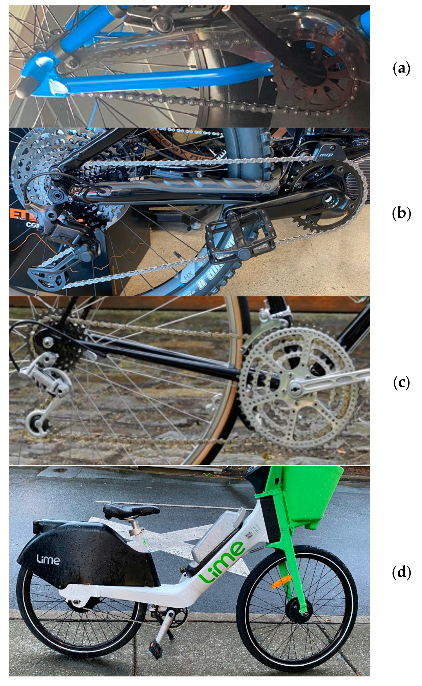
2.1. Roller Chain Drives

Most bicycles utilise the roller chain drive as their power transmission mechanism, with few exceptions like indoor exercise cycling machines or unconventional bikes. Although alternative transmission mechanisms like gears, hydraulics, strings, or shafts do exist, the chain drive system remains the most common due to its numerous advantages, including cost-effectiveness, compactness, efficiency, and customisability [18].
A typical roller chain drive consists of components such as the crank arms, pedals, bottom bracket, chainring, chain, cog, or cassette, and the closed-loop roller chain comprises a series of interconnected links with rollers and pins [19]. When the driving sprocket rotates, the chain is pulled along, causing the driven sprocket to rotate and transfer power from the driving shaft to the driven shaft [20]. A normal roller chain drive can achieve an efficiency of around 97–99% if it is working properly. Figure 2 illustrates the common components or features found in a bicycle drivetrain.

2.1.1. Cranksets and Sprockets

The bicycle crankset converts the reciprocating motion of the rider’s legs into rotational motion, driving the sprocket and chains to achieve power transmission in the bicycle. It consists of several components, including the crank arms, pedals, bottom bracket or shaft, and bearings, as shown in Figure 2.
The sprocket is a toothed wheel component that engages with the chain links to perform motion and power transmission. The sprockets can be categorised into front chainring and rear cog (or cassette for multispeed bikes), as in Figure 2c–f. The front chainring is the driving sprocket component that is attached to the crankset. Its function is to move and rotate the chain when the rider applies force to the pedals. Chainrings come in a variety of sizes and shapes, with the number of teeth ranging from 20T to 53T. Chainrings generally have evenly spaced teeth, but some chainrings are in wide–narrow teeth design [21], which contain two groups of teeth that have different thicknesses. This design ensures better engagement between the chain and sprockets, preventing chain slips-off during cycling activity [21]. Some chainrings even incorporate optional hook features along the rear flank to provide a better guide of the chain [22]. Wide–narrow teeth chainrings are commonly used in fixed gear and 1× bicycle drivetrains. There are also some specific designs like oval chainrings or compact chainrings.
The driven sprocket In a bicycle drivetrain Is typically attached to the rear wheel and can rotate or propel the bicycle forward when it is driven by the connected chain. The rear sprocket can be a single sprocket, known as a cog or freewheel, or multiple sprockets, known as a cassette (Figure 2f). The cassette is a gear block component that consists of several sprockets with different sizes and numbers of teeth. It allows the bicycle drivetrain to achieve different gear ratios and is present in most modern multispeed bikes. Both cogs and cassettes come in a range of sizes, which are typically measured in terms of the number of teeth on the sprocket. The gear ratio of the drivetrain is determined by the relationship between the number of teeth on the front chainring and the number of teeth on the rear cog or cassette. This indicates how many times the rear wheel turns in one rotation of the cranks. A larger cog with more teeth results in a lower gear ratio, providing more torque and lower rotating speed, thus making pedalling easier. On the other hand, a smaller cog with fewer teeth yields a higher gear ratio, enabling faster pedalling and greater speed [23].

2.1.2. Chains

The two main types of chains in bicycles are the standard bush roller chain used in traditional bikes and the bushingless roller chain used in modern bikes with derailleur systems [24], as shown in Figure 2g,h. A standard roller chain with bushing consists of outer plates/links, pins, rollers, and inner plates with sleeves (bushings). The inner pins are covered by multiple layers of free-to-rotate components like bushings and rollers [6]. The bushings are press-fitted into each link to reduce wear on the chain’s pins and plates. These bushings help the chain maintain its shape and provide an extended service life. Standard bush roller chains are often used in more economical bicycles, where durability and longevity are more important considerations. However, bush roller chains can be heavier and less efficient due to the added friction of the bushings. That is why in modern high-performance bicycles, standard roller chains have been replaced by bushingless chains.
The bushingless chain lacks the bushing component in its inner plate. The pins are designed to rotate directly on the inner plates. It is specifically designed to fit the gear-shifting features (derailleur) found in modern bicycles. This design reduces the weight of the chain and reduces the friction between the components by eliminating the bushings. In comparison to a standard roller chain, a bushingless chain is narrower, lighter, and more flexible. Higher-speed bicycle chains tend to have smaller plate thicknesses and inner and outer widths [25]. As a result, bushingless roller chains are typically more efficient than bush roller chains. In addition, the bushingless chain also has a small design change in its inner plate to provide better alignment and engagement with sprocket teeth, which can greatly eliminate the chance of the chain slipping off [26].

2.1.3. Chain Drive Configuration

Several studies have investigated the chain drive setup and configuration. Cho et al. [27] examined the optimal gear ratio for multispeed bicycles and proposed that reducing the number of gears without a loss of physiological efficiency would result in easier gear-shifting, as a fewer number of gears which are optimal can provide a performance equivalent to the multispeed gear system.
Van Soest [28] investigated the impact of bicycle chainring shape and geometry on overall performance with a focus on non-circular chainrings and developed algorithms and models that represent the gear ratio through the functions of crank angle and effective radius. It was concluded that chainring shapes have no significant impact on overall efficiency. Computer-aided engineering (CAE) tools and techniques have been used in the analysis of and improvement in chain drive geometry, such as the 3D modelling of roller chain drives [29,30].

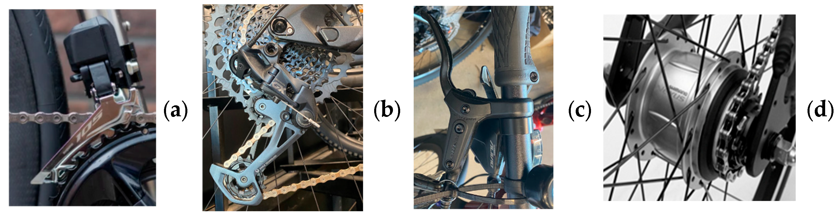
2.2. Gear-Shifting Mechanisms

In multispeed bicycles, the gear-shifting mechanisms are designed to enable riders to adjust the gear ratio of their bicycles, allowing them to maintain an efficient pedalling cadence and adapt to different terrains and riding conditions. The two main types of gear-shifting components are derailleurs (external) and internal gear hubs.

2.2.1. Derailleurs

The derailleur system was developed in the early 20th century [31]. It introduced the ability to easily move the roller chain between different chainrings or gears on the cassette block, allowing for a wider range of gear ratios. In modern multispeed bicycle drivetrains, the derailleur system typically includes a shifter, a derailleur, and a cassette or freewheel. The shifter serves as the control mechanism that riders use to adjust the gear ratio through a cable that runs to the derailleur. Derailleurs come in various types and designs, including front and rear derailleurs, as shown in Figure 3. It should be noted that the derailleur system introduces additional friction between the side plates of the roller chain, leading to energy loss at the articulation points due to higher bearing pressure. It also introduces extra tension in the return side of the drivetrain system. In experimental research on bicycle derailleur systems [32], the stability region in the derailleur system was reported, and a performance index called the stability ratio was introduced for better shift lever design in the rear derailleur.

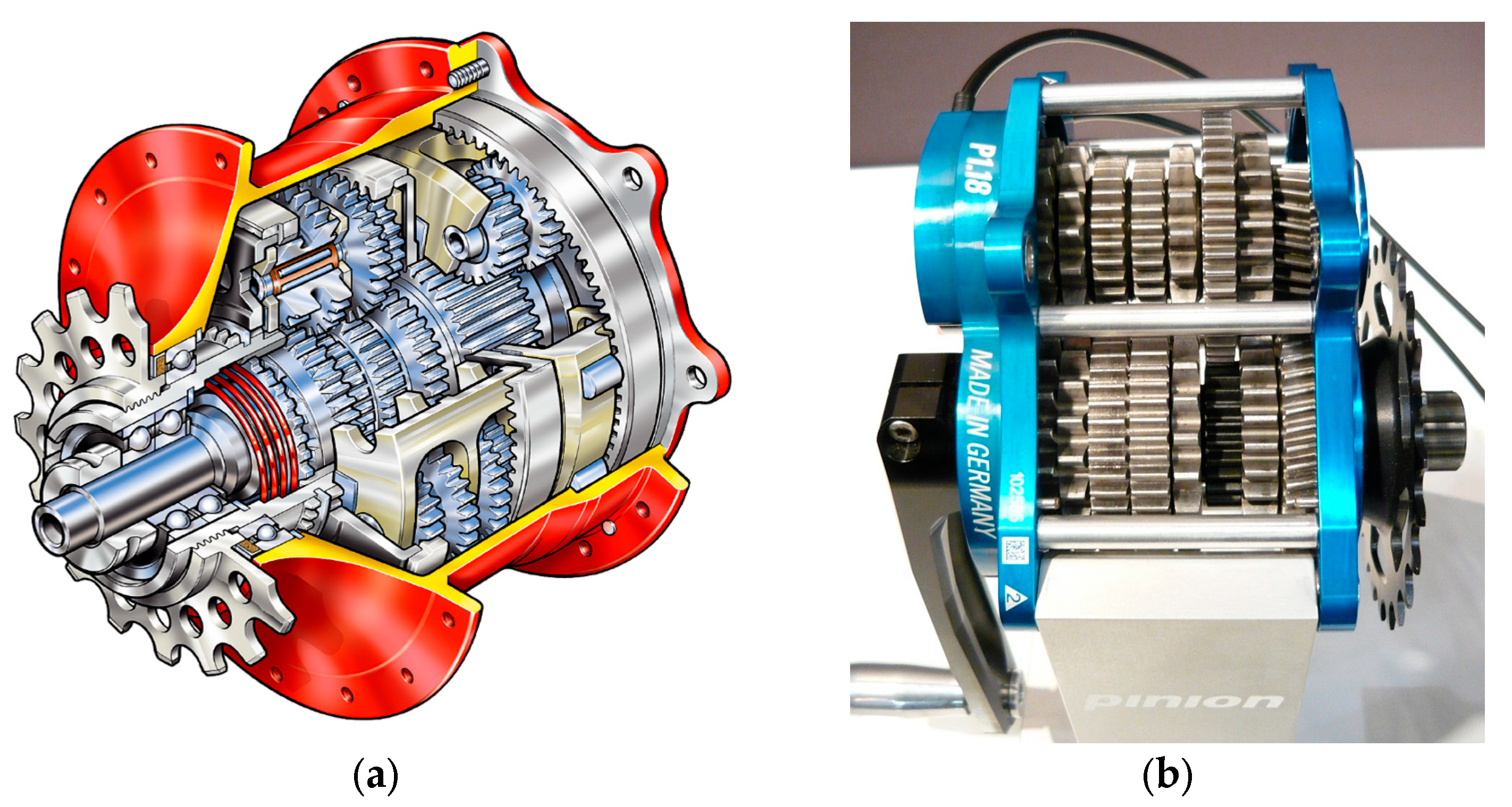
2.2.2. Gear Hubs and Gearboxes

The internal gear hub system (also known as hub gear), as shown in Figure 3d, is located within the rear wheel drive. It consists of various small mechanical elements like Pinions, gear rings, clutches, etc. The design is very compact and almost everything is sealed within a protective shell, usually with an epicyclic gear configuration [21]. The desired gear ratio is achieved through the interaction between the rear sprocket and the different positions of gears inside the internal hub. The main advantages of a planetary gear mechanism include low space occupancy, a high speed reduction ratio, and power transmission capabilities from the interaction of its gears of different sizes. It also allows for a better load distribution, which can further reduce wear and improve overall system durability [33]. On the other hand, hub gears are usually more expensive, heavier, and less efficient. Three-speed hubs were popular, but the number of gears offered in epicyclic hubs gradually increased. Hub gears can be found with two, three, five, seven, eight, nine, eleven, and fourteen speeds [33]. The 14-speed Rohloff 500/14 (shown in Figure 4a), made in Germany and launched in 1998, has been considered the king of hub gears due to its excellent performance that approaches the efficiency and range of a modern derailleur and provides more evenly spaced ratios, better reliability, and longer service life [33].
Another type of gear system for power transmission in bicycles is the gearbox. The gearbox is usually integrated into the frame near the crank, and it may be used in addition to or instead of derailleur gears or a hub gear [34]. A bicycle gearbox offers low-maintenance drivetrain and enables gears to be instantly shifted without the need to pedal. Two decades ago, Honda developed some top-secret bicycle gearbox drivetrains for downhill racing and won the world championships and five World Cup rounds [35]. Unfortunately, there are very limited information about the designs outside of their patent (US7503862B2, filed 2005) [36]. Cesar from UNNO bikes holds a recent patent (ES2684528A1, filed 2017) [37] for a similar gearbox, in which there is no derailleur; instead, it is the cassette that slides back and forth [35]. Shimano also filed their 13-speed gearbox patent (US 2019/0,011,037 A1) [38] that uses a form of derailleur. The Pinion gearbox is a relative newcomer. The gear is located in the bottom bracket position and requires frames to be made especially for this location [6]. Pinion gearboxes use spur gearing with two sub-units connected in sequence. Power is transmitted through only two sets of cogs. A photo of the Pinion P1.18 gearbox interior is shown in Figure 4b. The gearbox can be shifted through full-range gears all at once, shift part-way, or one at a time, whether stationary or while riding. The operation of this system is superbly explained at pinion.eu/en/technology/ [6].
In most cases, cyclists have to manually change gear ratio depending on resistance. The so-called autobike or automatically geared bicycle, whether with a derailleur or internally geared hub, is supposed to shift gears without intervention from the rider. The automatic speed changer can be divided into a step speed changer, including the fixed-axle gear type and the planetary gear type according to the gear train mechanism, and a continuously variable speed changer [39]. There have been some efforts in this pursuit, and some new patents have been filed in recent years, such as the US patent Automatic Transmission System for a Bicycle filed by Haven Mercer in 2023 (US 2023/0373592 A1) [40], and the patent “CVT automatic variator transmission for a bicycle” filed by inventor Peyman Asadi in 2019 (Patent number: 11885415; US20220213948A1) [41]. Nivex developed automatic transmission, which consists of a specially designed GPS unit and proprietary AI system that also control the derailleurs. The system interfaces with the power metre to detect whether a rider is attacking or taking it easy, to select the optimum gear for each situation, and it works with wireless derailleurs, such as SRAM eTap or the Shimano Di2 [42]. Shimano developed some new hardware and technologies towards automatic transmission, such as the new XT Di2, LinkGlide, the EP8-01 e-bike motor, and Auto Shift and Free Shift [43]. The Auto Shift, as the software, is a new mode that automatically shifts gears by employing speed, torque, and cadence sensors along with an algorithm to determine what gear you should be in and requiring hardware such as Di2 working with the derailleur and EP motor to execute a shift [43]. The development of automatic transmissions for bicycles is still at a very early stage and far more challenging than automatic transmissions for cars. So far, the peer reviewed literature is very limited, and more research efforts are expected.

2.3. Belt Drive Transmission

In lieu of the conventional steel chain-based drivetrains for bicycle transmission, there are other types of chainless drivetrains, such as those with toothed belts or with cardan shaft [44]. In the early days of cycling, flat belts were occasionally employed in the drive system of bicycles, but little progress was made due to the dependence on friction [33]. Since the 1960s, toothed belts have become more durable and efficient. Bridgestone launched its Picnica, a folding model bicycle, in the 1980s and claimed it as the world’s first series-produced belt drive bicycle [33]. The Gates Corporation, a market leader in drive belts, designed and made the belt drives used on the Strida from the 1980s onwards. It was not until 2007, when Gates developed the modern Carbon Drive system for bicycles, that the belt drive gained widespread popularity [33].
A belt drivetrain system consists of a belt that wraps around two pulleys or rotating shafts. Figure 5a shows a bicycle belt drive with horizontal fork ends and tugs for providing belt tension [45]. The belt drives for bicycles provide the benefits of being low maintenance, lubrication-free, lightweight, having a smooth operation, and enjoying a long life [45]. Modern transmission belts may consist of multiple layers, such as a protective top and bottom layer, with a flexible, high-resilience composite material in the middle. Gates’s Carbon Drive belt has strands of carbon fibres and teeth of nylon-jacketed polyurethane [33]. It has been reported that the belt drive can last upwards of 30,000 km/19,000 mi, which offers 3–4 times the service life of a chain [46]. Other belt drive manufacturers include Advanced Belt Drive, Continental AG, and Veer Cycle, to name a few [45].
However, there are several drawbacks to the belt drive, such as the large space requirement due to the belt’s width, material sensitivity to weather conditions, relatively high cost, and lower efficiency compared to a traditional roller chain drive [44]. As belts are one-piece and cannot be broken, the bicycle frame will need to be designed with a ‘belt splitter’ or an opening in the rear triangle. The belt’s width and pre-tension must be carefully chosen, calculated, and adjusted [6]. A tensioner needs to be added to a drive to apply tension to the belt. Since belts cannot run at an angle, they are not compatible with derailleur gears, which means that belts are only compatible with internally geared hubs (Figure 5b), Pinion gearboxes, or single-speed gears. A detailed comparison of the pros and cons of belt drive bicycles can be found in [47]. It should be noted that peer reviewed journal articles on bicycle belt drives are very limited. It is difficult to find papers in the literature specific to their tribological behaviour.

2.4. Drivetrain with Power-Assisted Module for E-Bikes

A major variation in the realm of bicycles is the introduction of e-bikes and power-assisted bikes. These innovations address some of the limitations of the traditional human-powered bicycles while retaining most of their advantages. E-bikes incorporate a motor or engine into their drivetrain to assist the cyclist’s pedalling action, as shown in Figure 1d. Other components, such as the chain–sprocket system, wheels, and frame, are largely the same as those of traditional bicycles, thus allowing existing research to remain relevant [48]. E-bikes have been steadily gaining popularity worldwide, with a notable increase in research focus over the years [49]. Hung and Lim [50] presented a comprehensive review on the development of e-bikes. Studies on e-bike performance and dynamic analysis, such as those by Arango, Lopez and Ceren [51], and Stackhouse and Dong [52], further highlight the growing interest and advancements in this field.

3. Power Transmission Mechanics and Efficiency

3.1. Mechanics of Power Loss and Factors Affecting Efficiency

The power transmission efficiency in bicycling can be defined as the power output at the driving wheel divided by the mechanical power input from the human body [6]. Although it is believed that the roller chain drive can achieve around 97–99% of power transmission efficiency [53], many factors can affect the drivetrain performance, such as friction in the chain drive and bearings, impact losses, and slip loss [6]. Existing research also stated that the efficiency of the chain drivetrain should be between 95% and 98.5% [54]. According to Sgamma et al. [55], the energy loss in a roller chain system can be attributed to several factors, including the frictional forces between the pins and bushings in the links as they articulate onto and off the sprockets, the impact forces generated when the chain rollers engage with the sprocket teeth, and the vibrations that result from these interactions. In a roller chain drive, friction is primarily due to the sliding actions between solid components [56], such as between a fixed pin and bushing. The chain is composed of many small components, and internal collision between components generates high amounts of friction and reduces overall transmission efficiency. There is also friction between a roller and the sprocket teeth due to meshing, and between the side plate and the side of the sprocket tooth [6]. When the chain sits on sprockets that are not completely in line, lateral offset occurs, introducing additional stress and friction to the side plates, further reducing performance [57]. If the chain is dirty or worn, some rolling friction may occur due to the presence of small particles.
Additionally, dynamic characteristics such as resonance, transverse vibration, and damping forces generated by the chain in motion can also contribute to power loss [53]. In a recent work, Lanaspeze et al. [58] showed that the power loss contributed by the meshing motion and the roller motion is in similar magnitude for a wide range of gear ratios and loading conditions in a simple two sprocket drive; however, it was also reported that power loss in the chain drive can be reduced by selecting larger gear ratios in race tandem bicycles [59]. Various ways of measuring chain drive efficiency, friction, and wear were compared in a recent review paper [60]. It was interesting to note that almost no research has investigated the effects of chain contamination on efficiency.
Impulse and vibration can occur due to meshing or interlock between the chain and sprockets, especially when the chain operates close to its natural frequency. Polygonal action is another issue that can arise when the chain wraps around a small diameter sprocket, resulting in periodic fluctuation and transverse displacement that reduces the system’s performance [61]. Other sources of energy loss include shock loads that occur during shaft revolution, inertia loads resulting from sudden momentary jams in the chains, centrifugal tension when the chain travels over the curved part between sprockets, additional loads when the chain is in a hanging or catenary state, as well as noise and heat generated during operation [62].

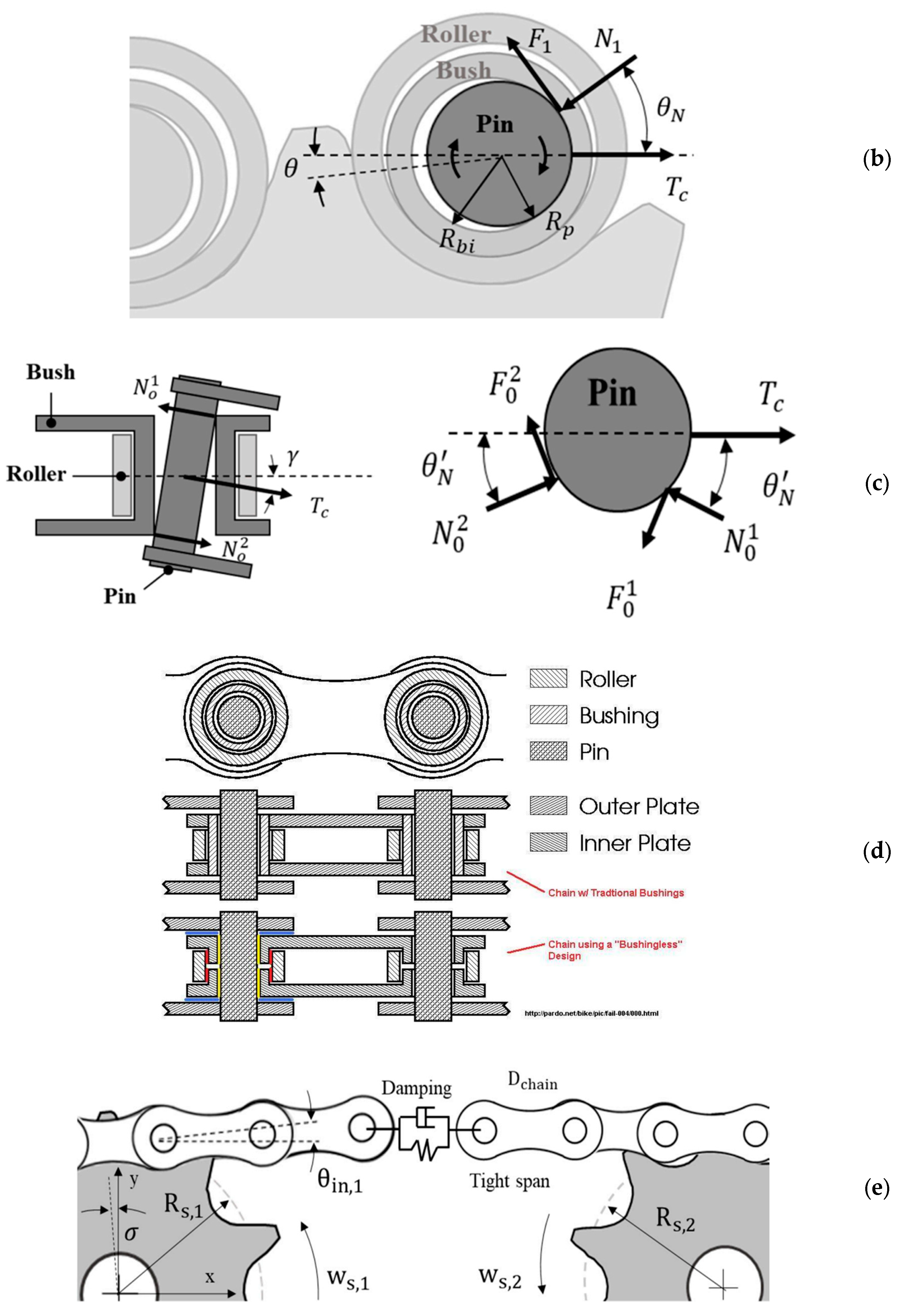
3.2. Contact Mechanics Between the Chain and Sprockets

Several researchers have investigated the contact mechanics between the chain and sprockets in order to better understand the drivetrain’s friction and kinematics. Pedersen et al. [63] measured the pseudo-penetration of a roller in the sprocket tooth and presented a more realistic circular tooth profile consisting of seven contact areas, enabling a detailed analysis of the contact vector and forces at different areas of the sprocket [64]. Ambrosio et al. [65] developed a planar roller chain drive model based on the cylindrical contact and real tooth profiles and studied the contact forces and trajectory of pins and bushings using the multibody dynamic approach. Further, it was reported [66,67,68] that the chain drive system also has other contact points such as the chain-to-chain guide and chain-to-tensioner, which may be present in some customised bikes to help hold the chain in place.
Meshing noise, vibration, and energy loss in chain drive transmission can occur during the meshing process. Binder and Mize [69] investigated roller chain drive strand vibration during operation. They modelled tight strand chains as tension strings with loaded masses at each roller centre to determine the natural frequency. Wang et al. [70,71] examined the stability of chain drive systems under periodic sprocket oscillations and proposed a numerical model with an impulse function based on their couple effects. Liu et al. [72] incorporated both longitudinal and transverse chain motions in a meshing impulse calculation and found that chain resonant and meshing frequency can affect the impact intensity or magnitude. Liu’s thesis [73] presented mathematical models for meshing and illustrated the relationship between meshing, impact, and noise and conducted several experiments to determine the meshing noise. Zheng et al. [74] studied the meshing noise of chain drives and found that the noise that radiated from both the drive and driven sprocket was small compared to the roller noise. The acoustical energy loss from meshing noise can be neglected in most cases.

3.3. Analysis of Forces

A pioneering analysis of chain drive forces was conducted by Binder and Covert [75], which focused on the impact velocity and energy transfer between the roller chain drive and the sprocket. They developed analytical equations to illustrate the roller–sprocket interaction, with the effects of friction ignored, and conducted laboratory tests to analyse the correlation between impact velocity and factors such as sprocket wear, roller failure, heat, and noise. Their research suggested that the impact energy, determined by sprocket speed, is closely related to roller breakage in the chain. This publication, along with a follow-up work by Binder [76], laid a foundation for understanding the mechanics of chain drives.
Naji and Marshek [77] analysed the geometric progressive load distribution in the roller chain drive around the sprocket teeth region (Figure 6a) and determined the effects of pitch difference, friction, and centrifugal forces on it. The interaction between the chain rollers and sprocket teeth at various positions was formulated, and the impact of various factors such as chain components, sprocket types, pitch size, and wrap or articulation angle on friction and centrifugal forces was examined, which in turn all influence the overall tension and loading on the sprocket teeth. Key findings reveal that the tooth load on a driven sprocket is higher than that of a driver sprocket due to the friction between the sprocket teeth and the chain rollers, and that the roller teeth of the sprocket are more susceptible to wear than the pin teeth. Additionally, a larger pitch size tends to increase the tension within the chain links. Naji and Marshek [78] also conducted an experimental study to determine the sprocket and roller chain load distributions, which was found to be independent of the elastic properties of the chain and the sprocket, and the lubrication as well. This study confirmed that the load distribution for the chain on a driver sprocket differed from that for a chain on a driven sprocket due to the different direction of the friction force. It was found that a larger pitch of the sprocket tooth can amplify the tension in the chain link. Collectively, these analyses and findings significantly advanced the understanding of the mechanics of roller chain drives.
Building upon the research findings of Naji and Marshek, Johnson and co-workers carried out further investigations during the 1990s. This included a more detailed model of the quasi-static contact phenomenon from the first principles by Kim and Johnson [80], which considered the external loading conditions, the curvature difference between the roller and the seating curve, the net error in the chain pitch, and the Coulomb friction in chain motion. Conwell and Johnson [81] experimentally investigated the dynamic behaviour of roller chain drives. They found that the tension in a chain link increases very rapidly as the link exits the driven sprocket and decreases rapidly when the link enters the drive sprocket.
Troedsson and Vedmar [82,83,84] conducted a comprehensive analysis of the entire chain drive system, focusing on the static and dynamic load distribution, and with the effects of elasticity to the link considered. They examined the forces in both the tight (top) and slack (bottom) regions of the chain, as well as in the driving and driven sprocket sections. Their load distribution model incorporates variables such as inertia, damping force, and moment in addition to the frictional force component to accurately represent the dynamic behaviour in chain drive operation. Kidd, Loch, and Reuben [57] published an important study on tribology in bicycle drivetrains. Through a comprehensive force analysis, they classified the bicycle drivetrain into different regions and defined all friction-producing points, as shown in Figure 6. The work formulated a power loss equation for these engagement points and indicated the effects of lateral behaviour and chain offset.
Lodge and Burgess [85] proposed an alternative approach for evaluating the forces and efficiency of roller chains with a novel chain efficiency model that considers only the geometry of the chain link on sprocket teeth and the associated force components around articulation points such as the pin, bushing, and roller. It was shown that frictional losses are a significant source of energy loss in chain transmission. The energy loss equations during pin and bushing articulation were developed using Coulomb’s law of friction (sliding), though it was also shown that at low torque, losses due to impact, adhesion, and/or vibration become more significant. A report in Friction Facts [79] identified the friction-producing mechanism and sliding surface for both bush and bushingless bicycle chains, which can be used to further develop an efficiency model specifically for bicycle chains based on the work of Lodge and Burgess [85]. Although it was traditionally assumed that small sprockets are the best solution for whole life cost and performance, Lodge and Burgess [86,87] disproved this through an experimental investigation. They introduced a chart for the selection of optimum chain and sprocket size and demonstrated that significant energy savings can be achieved by using it. Their findings support the view held by some researchers that using larger sprockets, despite the increase in mass and inertia, can enhance transmission efficiency due to reduced frictional losses. Binder and Covert [75] showed that when the number of teeth in the sprocket was increased, the impact energy decreased, and the number of failures was also reduced. Hollingworth and Hills [88] attributed the reduction in power loss to the smaller angles of articulation imposed on the chain when using sprockets with a larger number of teeth.
Spicer et al. [89] investigated the efficiency of bicycle chain drives both experimentally and theoretically. Their findings revealed that the primary factors affecting efficiency are sprocket size and chain tension, with friction surprisingly accounting for only a small portion of overall losses. In a subsequent study, Spicer [90] analysed the non-linear elastic behaviour in bicycle chain drives and its impact on transmission efficiency and developed mathematical models of power loss, taking into account the effects of tensions, pin–bushing interaction, chain extension, and other properties like Young’s modulus. It was concluded that power loss decreases with an increase in roller chain tension during operation. Zhang and Tak [91] proposed a transmission efficiency model for roller chain drive based on sliding friction and damping force, which accounts for the effects of lateral offset and other operating parameters. Sgamma et al. [55] developed a phenomenological model for chain transmissions efficiency and introduced a new parameter called chain tension efficiency to model the distribution of losses within the system. It was observed that the efficiency increases nearly linearly with the number of teeth of both sprockets. In addition, the effectiveness of finite element analysis (FEA) as a tool in determining the forces, stresses, and displacements of the roller chain drive under various tension and loading conditions was demonstrated by Nikhil et al. [92], as well as Dhage and Diwate [93]. The integration of FEA with the multibody system (MBS) technique has been explored to enhance the analysis of the mechanics and dynamics of roller chain drives [94].

3.4. Kinematic and Dynamic Behaviour in Bicycle Drivetrains

Various studies of the kinematics and dynamics of roller chain drives have been conducted, aiming to develop numerical models based on force and motion analysis. Lai et al. [95] analysed the motion of the rear derailleur shifting process in bicycle chains and presented a design methodology for the tooth profile and changer mechanism. The jumping-over-teeth phenomenon and the impact on the overall chain drive performance were discussed by Wang, Zheng, and Zhang [96]. Ma and Chiou [97] studied the condition of the chain link during the shifting process and proposed an optimal path model for drivetrain up-shifting. The path is formed by several bent chain links that can sustain the yaw and roll for the sprocket tooth chamber, and the path can shorten the required up-shifting distance, decrease the phase angle, promote efficiency, and reduce movement yield by the derailleur tappet pressure.
Pedersen [98] developed mathematical models to predict the chain drive’s kinematic, force, damping, and other parameters based on a multibody system dynamic analysis approach. Wu et al. [99] performed a kinematic analysis for an eight-speed bicycle transmission hub employing a fundamental circuit method. It included diagrams that illustrate the power flow paths of the transmission hub. Omar [100,101] modelled the bicycle chain with bushings using multibody dynamics based on spatial algebra. Non-linear kinematic and dynamic equations of motion between different bodies are derived based on the spatial Cartesian coordinates and joint variables in the roller chain link. This approach can be applied for the investigation of ride and shift quality, contact forces, wear prediction, and noise emission.

4. Tribological Performance in Bicycle Drivetrains

4.1. Wear

4.1.1. Mechanics of Wear in Chain Drives

Mechanical wear occurs due to the relative motion between surfaces in contact. Components like chains and sprockets, which experience elevated friction during operation, are particularly prone to wear. This wear has the potential to cause a deterioration in functionality, ultimately leading to material failure. There are different types of wear, including abrasive, sliding, rolling, impact, corrosion, and erosion. In roller chain drives, the primary forms of wear are abrasive and sliding [102]. Abrasive wear occurs when materials rub against each other, causing the softer material to break off due to cutting, ploughing, or surface fracturing of a harder material. During sliding, where there is relative movement between the pin and bush in a roller chain, particularly when passing over sprockets, joint abrasion occurs, with wear concentrated mainly in the contact zone between the pin and bush [103]. The smoothness of the material influences this wear, and polishing the object’s surface can effectively reduce it. Sliding or adhesive wear occurs when objects are in contact, and their surface asperities collide, forming adhesion that leads to material transfer [104]. Adhesive wear reduces if metal oxide films are present on the material surface, as they can minimise or prevent real contact between materials [105]. Various regions of the chain drive, including the chain pin–bush, bush–roller, roller–sprocket teeth, and side plates, are subject to contact and wear. Figure 7 illustrates comparisons of some new and worn components of roller chain drives and sprockets.
Elongation is a clear indication of roller chain wear. Wear-induced pitch elongation of the chain not only causes significant variations in static load but also generates additional dynamic load on the drive and driven sprockets, leading to the obvious vibration of the whole chain [106]. Once the chain elongation exceeds 0.5–0.75% in the elongation checker tool, it needs to be replaced before it further damages other drivetrain components [107]. Regarding the sprocket, wear mainly occurs in the gear teeth region, resulting in chipping or material removal. When the outer surface of the gear teeth becomes worn or rough, this affects the contact between the chain and sprocket, resulting in poor fit and accelerated chain wear, reduced transmission of motion, and reduced power efficiency. Although many cyclists assume that the sprockets in the chain drive system should be as small as possible, a study by Burgess [56] showed that large sprockets are best for cycling as a larger chain set has the advantage of reducing chain forces and thus internal friction losses, which also leads to lower wear rates. It was claimed that doubling sprocket size will have the effect of doubling the wear life [56].

4.1.2. Detection of Chain Drive Wear

Wear in roller chains can be detected using various approaches. Measuring elongation with chain gauges or checker tools is the method commonly used by cyclists. Becker et al. [108] introduced two chain wear test rigs for friction and wear investigations, including a chain joint tribometer for single-chain joint analysis, as shown in Figure 8 [109], which successfully identified the run-in wear period and the state of steady wear in an initial test. This test rig enables wear and friction measurement and investigation on all parts inside a chain joint like pin and bush [109] and has been used to investigate the influence of triboactive coating on the joint wear of grease-lubricated roller chains [103]. Zhou introduced a mathematical method as a tool to facilitate the test rig design for chain wear testing [110]. Rosenkranz et al. [111] employed a specially modified, commercial ball-on-disc tribometer to investigate the friction and wear behaviour of laser-patterned chain links and found that cross-like patterns can reduce friction and wear noticeably. Saito, Noda, and Sano [112] developed a testing machine that can simulate realistic wear conditions on roller chain links in a short amount of time using limited resources and energy in generating a worn roller chain for wear testing and evaluation experiments. The wear resistance of roller chain components can be enhanced through material selection, optimised manufacturing processes, heat treatment, and surface coatings [103]. It should be noted that while these studies are not specific to bicycle drivetrains, the mechanisms they explore are relatively generic and can be applied to bicycle drivetrains.

4.2. Lubrication

4.2.1. Types of Chain Drive Lubrication

Lubrication is the use of a lubricant to reduce friction and wear between two contact surfaces. Proper application of lubricant can increase the transmission smoothness and efficiency of the chain drive by up to 5% [113,114]. There are many types of lubricants designed for different uses and varied opinions of what is the best lubricant. Lubricants are primarily categorised based on their phase, i.e., oil-based liquids (natural, mineral, or synthetic oil), non-oil liquids, cohesive types (such as waxes, greases, or pastes), and solid dry lubricants [115]. Performance and efficiency are the most crucial criteria when selecting lubrication.
It is agreed that the type of riding and location best determines the type of chain lubrication, as different types of lubricants are suited for different situations [116]. Some bike lubricants have features that help minimise wear, corrosion, oxidation, water resistance, or grime protection. In dry and dusty areas, dry lubricants (thin or light lubricants in a volatile carrier) would do better as they attract and hold less dust and grit than oils that remain moist. Wax-based lubes are also popular that are applied and left to dry. On the other hand, in wet and humid areas with a lot of precipitation, a thicker lubricant is commonly used that will adhere to the chain [116]. For the lubrication of bicycle chain transmission, water resistance and viscosity play an important role in lubricant parameter selection [117]. It was suggested that the mixed grade lubricant performs better in the rainy operating environment through an experimental investigation by Shen et al. [117].
Most roller chains and bicycle drivetrains use synthetic or mineral oil lubricants with additives [118]. Compared to grease or wax, liquid synthetic oil has low viscosity and a high penetration rate. It can easily slip into the tight gaps between the chain’s components and form a protection film on the metal surface. Additives are used to maintain lubricant performance under various cycling environments. One advantage of liquid lubricant is that it can be directly applied to the system while the chain drive is in operation, whereas grease or solid lubricants require stopping the chain movement before applying. Liquid lubricants also take less time to take effect compared to dry lubricants, wax, or grease products. As a result, many bicycle riders prefer using liquid lubricants for their drivetrain and sometimes use dry or grease lubricants in the preparation stage or after cycling. Liquid lubricants can be applied in various ways, including dripping from a bottle/nozzle; constant bathing or spraying; partially dipping in a pool of lubricant; fully soaking/submerging the parts; operating within a closed container full of lubricant, etc. [119]. However, only the bottle dripping method is suitable for use while riding a bicycle.

4.2.2. Effects of Chain Drive Lubrication

Due to the extremely narrow spacing between chain components, with little to no separation between opposing surfaces, lubrication in roller chain drive applications typically operates under the boundary lubrication regime, which is featured with a high friction coefficient and thin lubricating film, although all lubrication regimes are encountered in elite cycling. Actually, the lubrication regime can be affected by chain tension, alignment and velocity, sprocket size, lubricants, and contamination, and it also influences the coefficient of friction [60].
There have been some experimental studies [120,121,122] investigating the efficiency and effects of lubricants on chain drives and bicycle drivetrains. The key findings are as follows:
  • Dry lubricant, such as paraffin wax, offers superior performance in terms of efficiency, longevity, and resistance to water and dirt. However, the application method is fully immersive and time-consuming.
  • Liquid lubricants with additives such as PTFE or wax generally exhibit better performance.
  • Renewable lubricants derived from bio-derived oils can achieve good friction reduction but may lack resistance to oxidation and heat.
  • Wax and grease have a longer lasting time than liquid products but are difficult to clean afterwards.
  • Wet lubricants and weather conditions can attract contaminants, leading to increased friction in the chain. Thus, resetting the lubrication is recommended if cycling off-road.
  • High temperatures can reduce oil viscosity, resulting in a smaller lubrication film interacting with contact surface asperities. Clean oil can improve performance, but the presence of dust, debris, or particles can introduce additional friction to the system.
  • The lubrication method significantly impacts efficiency. Frequent lubrication to the drivetrain during cycling, such as drip or spray application, is recommended. While immersive soaking offers better results, it is impractical for typical cycling conditions.

5. Conclusions and Future Perspectives

This paper presents a comprehensive literature review of bicycle drivetrain systems, with a primary emphasis on the power transmission and tribological performance of roller chain drives. It discussed various aspects of bicycle drivetrains, exploring the diversity in their core components and mechanisms. This review consolidates research findings pertaining to power transmission within the bicycle drivetrain systems, encompassing discussion on power loss mechanisms, efficiency factors, contact mechanics, force analysis, as well as the kinematic and dynamic behaviour of the bicycle roller chain drive mechanisms. Furthermore, different facets of friction, wear, and lubrication are examined, outlining their relevance to the bicycle drivetrain systems. The findings of this work can inspire further academic research on advancing our scientific understanding of the drivetrain systems, create new tools for performance simulation and product development for higher efficiency lower costs to benefit cyclists and the wider community, and promote collaboration between researchers and industry to tackle technical challenges for product innovations.
While the demand for bicycles remains high and the drivetrain remains a fundamental element of any bicycle, there exists immense potential in this field of bicycle drivetrain technology. Some future perspectives in relevant research can be outlined as follows to underscore potential avenues for exploration and development.
  • Modern bicycle drivetrains have widely utilised bushingless chains and the wide–narrow teeth chainrings, which deviate from the conventional design of roller chain drive systems. However, there is very little research that specifically delves into these types of chain drives. Investigating the performance and characteristics of bushingless chains can provide valuable insights into their physical properties, efficiencies, and tribological behaviours. Achievements on understanding the friction force, wear resistance, dynamic characteristics, and development of corresponding simulation models can facilitate industry to improve products.
  • There is a critical need for research and innovations in friction reduction within the drivetrain to enhance tribological performance. This can be achieved through innovative lubrication techniques, surface treatments, and exploring the potential of novel materials and coatings to minimise wear and increase efficiency. The integration of advanced materials, such as light alloys and ceramics, can also play a pivotal role in developing more durable and lightweight drivetrain components.
  • The trend in modelling and simulation for bicycle drivetrain research involves a more profound understanding of the power transmission mechanisms and an increasing reliance on advanced computational tools. It allows for a detailed analysis and optimisation of various aspects of the drivetrain system. Accurate characterisation of the empirical parameters, including friction coefficients, is crucial. Further research is needed to explore the impact of key components in the chain drive, such as pin, bushing, and roller dimensions, on power loss and wear rates. This investigation will aid in designing more efficient and durable chain drives.
  • The electric bicycle industry has experienced significant development in recent years. The adoption of electronic drivetrains, including electronic shifting systems and advanced motor controllers, is on the rise. Innovations such as internal gear hubs, belt drives, and automatic transmission are gaining popularity. There is a need to make them lightweight, more reliable, and affordable. This evolving landscape presents new challenges and opportunities that warrant special attention in drivetrain research.

Author Contributions

Conceptualisation, Y.W.L., O.M., D.V.D. and H.L.; data curation, Y.W.L. and H.L.; writing—original draft preparation, Y.W.L.; writing—review and editing, Y.W.L. and H.L.; supervision, O.M., D.V.D. and H.L. All authors have read and agreed to the published version of the manuscript.

Funding

Y.L. receives a PhD scholarship funded by GRIFFITH UNIVERSITY and RIDE MECHANICS.

Acknowledgments

During the preparation of this work, the authors used ChatGPT to improve the language and readability of the article. After using this tool/service, the authors reviewed and edited the content as needed and take full responsibility for the content of the publication.

Conflicts of Interest

Author O.M. was employed by the company Ride Mechanic Pty Ltd. The remaining authors declare that the research was conducted in the absence of any commercial or financial relationships that could be construed as a potential conflict of interest.

References

  1. Tabascio, A.; Tiznado-Aitken, I.; Harris, D.; Farber, S. Assessing the potential of cycling growth in Toronto, Canada. Int. J. Sustain. Transp. 2023, 17, 1370–1383. [Google Scholar] [CrossRef]
  2. Oliveira, F.; Nery, D.; Costa, D.G.; Silva, I. A Survey of Technologies and Recent Developments for Sustainable Smart Cycling. Sustainability 2021, 13, 3422. [Google Scholar] [CrossRef]
  3. Chen, W.; Carstensen, T.A.; Wang, R.; Derrible, S.; Rueda, D.R.; Nieuwenhuijsen, M.J.; Liu, G. Historical patterns and sustainability implications of worldwide bicycle ownership and use. Commun. Earth Environ. 2022, 3, 171. [Google Scholar] [CrossRef]
  4. Thomas, F. 2022 World Bicycle Industry Report: An Industry Addicted to N + 1. a-dbikes.com. 2024. Available online: https://a-dbikes.com/blogs/news/analysis-of-world-bicycle-industry-association-report-2022?srsltid=AfmBOopdwK0F6VwbsJTcTIYJlrFfi_YKhHirQEaOZtCtEgQ8H9DYyouc&utm_source=chatgpt.com (accessed on 14 January 2025).
  5. Grand View Research. Bicycle Market Analysis Report. 2023. Available online: https://www.grandviewresearch.com/industry-analysis/bicycle-market#:~:text=ReportOverview,anticipatedtopropelmarketgrowth (accessed on 1 February 2023).
  6. Wilson, D.G.; Schmidt, T. Bicycling Science, 4th ed.; Massachusetts Institute of Technology: Cambridge, MA, USA, 2020. [Google Scholar]
  7. Rérat, P. The rise of the e-bike: Towards an extension of the practice of cycling? Mobilities 2021, 16, 423–439. [Google Scholar] [CrossRef]
  8. Teixeira, J.F.; Silva, C.; Moura, F. Empirical evidence on the impacts of bikesharing: A literature review. Transp. Rev. 2021, 41, 329–351. [Google Scholar] [CrossRef]
  9. Popan, C. Introduction Tips of the cycling iceberg. In Bicycle Utopias: Imagining Fast and Slow Cycling Futures; Taylor & Francis Group: Abingdon, UK, 2018. [Google Scholar] [CrossRef]
  10. Malizia, F.; Blocken, B. Cyclist aerodynamics through time: Better, faster, stronger. J. Wind. Eng. Ind. Aerodyn. 2021, 214, 104673. [Google Scholar] [CrossRef]
  11. Holmberg, K.; Erdemir, A. Influence of tribology on global energy consumption, costs and emissions. Friction 2017, 5, 263–284. [Google Scholar] [CrossRef]
  12. Underwood, L.; Jermy, M. Determining optimal pacing strategy for the track cycling individual pursuit event with a fixed energy mathematical model. Sports Eng. 2014, 17, 183–196. [Google Scholar] [CrossRef]
  13. Pickering, C.; Byrne, J. The benefits of publishing systematic quantitative literature reviews for PhD candidates and other early-career researchers. High. Educ. Res. Dev. 2014, 33, 534–548. [Google Scholar] [CrossRef]
  14. Lovejoy, K.; Handy, S. Developments in bicycle equipment and its role in promoting cycling as a travel mode. In City Cycling; MIT Press: Cambridge, MA, USA, 2012; pp. 75–104. [Google Scholar]
  15. Stead Cycles. Single Speed vs Geared Bikes. 2023. Available online: https://www.steadcycles.com.au/singlespeed-vs-gearedbikes/ (accessed on 23 March 2023).
  16. Thakur, T.S.; Babu, P.M. Evolution of Bicycles and their utility as Fitness aids—A Review. IOSR J. Nurs. Health Sci. 2019, 8, 19–23. [Google Scholar]
  17. Dawson, T. H.R.Morris 1968, with Beautifully Carved Lugwork. Vintage Bicycle Blog. 2020. Available online: https://vintagebicycle.wordpress.com/page/2/ (accessed on 5 March 2024).
  18. Malppan, G.J.; Sunny, T. A Review on Design Developments in Bicycle. Int. Res. J. Eng. Technol. 2015, 2, 1794–1799. Available online: https://www.researchgate.net/profile/Tom-Sunny-2/publication/280698135_A_Review_on_Design_Developments_in_Bicycle/links/602ef0a292851c4ed5804753/A-Review-on-Design-Developments-in-Bicycle.pdf (accessed on 28 October 2024).
  19. Urunkar, R.U.; Deshpande, P.P. Study of Drive Mechanisms of Bicycle, Tricycle or Like Vehicles to Optimize Operating Performance-A Review. J. Eng. Res. Appl. 2014, 4, 214–219. Available online: https://www.ijera.com/papers/Vol4_issue1/Version%202/AC4102214219.pdf (accessed on 28 October 2024).
  20. Stratview Research. Belts, Chains and Gears: How Power Transmission Works. EETech Media. 2022. Available online: https://eepower.com/technical-articles/belts-chains-and-gears-how-power-transmission-works/# (accessed on 24 March 2023).
  21. SRAM. Spare Parts Catalog; SRAM: Chicago, IL, USA, 2023. [Google Scholar] [CrossRef]
  22. Reiter, M.; Florczyk, R.; Braedt, H. Chainring. U.S. Patent US 11,110,991 B2, 7 September 2021. Available online: https://patents.justia.com/patent/11110991 (accessed on 10 January 2025).
  23. Livesey, A. Bicycle Engineering and Technology; Routledge, Taylor & Francis Group: Abingdon, UK, 2021. [Google Scholar]
  24. Berto, F.J. The Sunset of Suntour. In Proceedings of the 9th International Cycling History Conference, Ottawa, ON, Canada, 19–21 August 1998; Volume 9, pp. 116–140. Available online: https://www.mechanischehirngespinnste.de/wp-content/uploads/2021/07/sunset_of_suntour.pdf (accessed on 28 October 2024).
  25. Wagner, M.; Koch, T.; Kuehne, I.; Frey, A. Analysis of Static Stress in a Bicycle Chain Plate. In Proceedings of the 2015 COMSOL Conference, Grenoble, France, 14–16 October 2015; pp. 1–6. [Google Scholar]
  26. Dupoyet, G.J.M. The Transmission Chain. Published Online 1981. Available online: https://ridemechanic.com.au/wp-content/uploads/2019/08/Sedis_US4265134A.pdf (accessed on 28 October 2024).
  27. Cho, C.K.; Yun, M.H.; Yoon, C.S.; Lee, M.W. An ergonomic study on the optimal gear ratio for a multi-speed bicycle. Int. J. Ind. Ergon. 1999, 23, 95–100. [Google Scholar] [CrossRef]
  28. Van Soest, A.J. From bicycle chain ring shape to gear ratio : Algorithm and examples. J. Biomech. 2014, 47, 281–283. [Google Scholar] [CrossRef] [PubMed]
  29. Mo, Y.; Xu, X. Solidworks chain drive design and 3D modeling techniques. Appl. Mech. Mater. 2012, 215–216, 1146–1149. [Google Scholar] [CrossRef]
  30. Wang, L. Simulation of chain drive based on MSC. Visual nastran 4D. Appl. Mech. Mater. 2012, 101–102, 267–270. [Google Scholar] [CrossRef]
  31. Suciu, P. When Were Bicycle Gears Invented? Bikeradar. 2012. Available online: https://www.bikeradar.com/features/when-were-bicycle-gears-invented/#:~:text=In1895FrenchmanJeanLoubeyre,thePolyceler(multispeed).&text=Thederailleurwasdevelopedin,allowedgearingtobeused (accessed on 4 May 2023).
  32. Lin, T.Y.; Tseng, C.H.; Fong, Z.H. An experimental approach characterizing rear bicycle derailleur systems Part II: The stability region and its applications. Int. J. Veh. Des. 1998, 19, 371–384. [Google Scholar]
  33. Hadland, T.; Lessing, H. Bicycle Design: An Illustrated History; The MIT Press: Cambridge, MA, USA, 2014. [Google Scholar]
  34. Wikipedia Contributors. Gearbox Bicycle. Wikipedia, The Free Encyclopedia. 2024. Available online: https://en.wikipedia.org/w/index.php?title=Gearbox_bicycle&oldid=1225189249 (accessed on 11 January 2025).
  35. Denham, A. Inside The Revolutionary Honda Bicycle Gearboxes (All 3 Generations). cyclingabout.com. 2023. Available online: https://www.cyclingabout.com/inside-the-revolutionary-honda-bicycle-gearboxes/ (accessed on 11 January 2025).
  36. Kaga, H.; Kimura, T. Transmission with Internal Protective Shield and Bicycle Incorporating Same. U.S. Patent US7503862B2, 17 March 2009. Available online: https://patents.google.com/patent/US7503862B2/en (accessed on 10 January 2025).
  37. Sistema de Transmisión para Bicicleta, by César ROJO VIDAL. Spain patent ES2684528A1, 30 March 2017. Available online: https://patents.google.com/patent/ES2684528A1/es (accessed on 10 January 2025).
  38. Iwai, T.; Taniguchi, M. Sliding Component and Bicycle Internal Transmission Device. U.S. Patent US2019/0011037 A1, 10 July 2017. Available online: https://patentimages.storage.googleapis.com/ac/c6/46/60b59fb9800461/US20190011037A1.pdf (accessed on 10 January 2025).
  39. Hsieh, L.c. The Kinematic Design of Automatic Gear Transmissions for Bicycles. Eng. Lett. 2008, 16. Available online: https://www.engineeringletters.com/issues_v16/issue_3/EL_16_3_17.pdf (accessed on 10 January 2025).
  40. Mercer, H. Automatic Transmission System for a Bicycle. U.S. Patent US20230373592A1, 23 November 2023. Available online: https://patents.google.com/patent/US20230373592A1/en (accessed on 10 January 2025).
  41. Asadi, P. Cvt Automatic Variator Transmission for a Bicycle. U.S. Patent US20220213948A1, 7 July 2022. Available online: https://patents.google.com/patent/US20220213948A1/en (accessed on 10 January 2025).
  42. Heine, J. Nivex Automatic Transmission. renehersecycles.com. 2023. Available online: https://www.renehersecycles.com/nivex-automatic-transmission/#:~:text=ThenewNivexautomatictransmission,optimumgearforeachsituation (accessed on 11 January 2025).
  43. Roggeman, P.; Shimano Auto Shifts Into the Future. nsmb.com. 2023. Available online: https://nsmb.com/articles/shimano-auto-shifts-into-the-future/#:~:text=Specs*1x12-speedwith10-51tCassetteOptions.,Di2RightShiftSwitchandI-SPECEV (accessed on 11 January 2025).
  44. Levarda, E. Bicycle transmissions. IOP Conf. Ser. Mater. Sci. Eng. 2018, 444, 052013. [Google Scholar] [CrossRef]
  45. Wikipedia Contributors. Belt-Driven Bicycle. Wikipedia, The Free Encyclopedia. 2024. Available online: https://en.wikipedia.org/w/index.php?title=Belt-driven_bicycle&oldid=1227938963 (accessed on 10 January 2025).
  46. Denham, A.; Gates Carbon Belt Drive: Everything You Ever Need to Know. cyclingabout.com. 2019. Available online: https://www.cyclingabout.com/carbon-belt-drive-everything-you-ever-need-to-know/ (accessed on 10 January 2025).
  47. Norman, P. What Are Belt Drive Bikes and Why Are They a Popular Alternative to a Bike with a Chain? bikeradar.com. 2024. Available online: https://www.bikeradar.com/advice/buyers-guides/belt-drive-bicycles/ (accessed on 10 January 2025).
  48. Abagnale, C.; Strano, S.; Cardone, M.; Iodice, P.; Terzo, M.; Vorraro, G. Design and Development of a Test Rig for E-bike Performance Evaluation. SAE Tech. Pap. 2015, 2015, 1–7. [Google Scholar] [CrossRef]
  49. Deleenheer, W.; Jáneš, L.; Jayakumar, A. Development of an Electric Bicycle for a Sharing System in Prague. Acta Polytech. CTU Proc. 2017, 12, 24. [Google Scholar] [CrossRef]
  50. Hung, N.B.; Lim, O. A review of history, development, design and research of electric bicycles. Appl. Energy 2020, 260, 114323. [Google Scholar] [CrossRef]
  51. Arango, I.; Lopez, C.; Ceren, A. Improving the autonomy of a mid-drive motor electric bicycle based on system efficiency maps and its performance. World Electr. Veh. J. 2021, 12, 59. [Google Scholar] [CrossRef]
  52. Stackhouse, R.V.; Dong, Z. Development of electric bicycle performance testing techniques and adaptable electric bicycle power system. In Proceedings of the2007 International Design Engineering Technical Conferences and Computers and Information in Engineering Conference, Las Vegas, NV, USA, 4–7 September 2007; Volume 3, pp. 1113–1124. [Google Scholar] [CrossRef]
  53. Zhang, S.P.; Tak, T.O. Efficiency evaluation of electric bicycle power transmission systems. Sustainability 2021, 13, 10988. [Google Scholar] [CrossRef]
  54. Lukes, R.; Hart, J.; Haake, S. An analytical model for track cycling. Proc. Inst. Mech. Eng. Part P J. Sports Eng. Technol. 2012, 226, 143–151. [Google Scholar] [CrossRef]
  55. Sgamma, M.; Bucchi, F.; Frendo, F. A phenomenological model for chain transmissions efficiency. IOP Conf. Ser. Mater. Sci. Eng. 2021, 1038, 012060. [Google Scholar] [CrossRef]
  56. Burgess, S.C. Improving cycling performance with large sprockets. Sports Eng. 1999, 1, 107–113. [Google Scholar] [CrossRef]
  57. Kidd, M.D.; Loch, N.E.; Reuben, R.L. Bicycle Chain Efficiency; Heriot-Watt University: Edinburgh, UK, 2000. [Google Scholar] [CrossRef]
  58. Lanaspeze, G.; Guilbert, B.; Manin, L.; Ville, F. Preliminary modelling of power losses in roller chain drive: Application to single speed cycling. Mech. Ind. 2022, 23, 217–226. [Google Scholar] [CrossRef]
  59. Smit, A.; van der Zwaard, S.; Janssen, I.; Janssen, T.W.J. Power loss of the chain drive in a race tandem bicycle. Sports Eng. 2023, 26, 1–8. [Google Scholar] [CrossRef]
  60. Aubert, R.; Roizard, X.; Grappe, F.; Lallemand, F. Tribological devices in cycling: A review. Proc. Inst. Mech. Eng. Part P J. Sports Eng. Technol. 2023. [Google Scholar] [CrossRef]
  61. Bouillon, G.; Tordion, G.V. On polygonal action in roller chain drives. J. Manuf. Sci. Eng. Trans. ASME 1965, 87, 243–251. [Google Scholar] [CrossRef]
  62. Bhoite, T.D.; Pawar, P.M.; Gaikwad, B.D. Fea Based Study of Effect of Radial Variation of Outer Link in A Typical Roller Chain Link Assembly. Int. J. Mech. Ind. Eng. 2012, 1, 69–74. [Google Scholar] [CrossRef]
  63. Pedersen, S.L.; Hansen, J.M.; Ambrósio, J.A.C. A roller chain drive model including contact with guide-bars. Multibody Syst. Dyn. 2004, 12, 285–301. [Google Scholar] [CrossRef]
  64. Pedersen, S.L. Model of contact between rollers and sprockets in chain-drive systems. Arch. Appl. Mech. 2005, 74, 489–508. [Google Scholar] [CrossRef]
  65. Ambrosio, J.; Malça, C.; Ramalho, A. Planar roller chain drive dynamics using a cylindrical contact force model. Mech. Based Des. Struct. Mach. 2016, 44, 109–122. [Google Scholar] [CrossRef]
  66. Papuc, R.; Velicu, R. Tribological Study of Guide-Chain Contact. Ann. ORADEA Univ. Fascicle Manag. Technol. Eng. 2013, XXII, 257–260. [Google Scholar] [CrossRef]
  67. Choi, W.; Johnson, G.E. Transverse vibration of roller chain drive with tensioner. In Proceedings of the International Design Engineering Technical Conferences and Computers and Information in Engineering Conference, Albuquerque, NM, USA, 19–22 September 1993; Volume 11795, pp. 19–28. [Google Scholar] [CrossRef]
  68. Dwyer-Joyce, R.S.; Lewis, R.; Ward, A.; Patterson, E.A. Determination of impact stresses in an automotive chain drive component. SAE Tech. Pap. 2006, 2006, 1–9. [Google Scholar] [CrossRef]
  69. Binder, R.C.; Mize, G.G. Strand vibrations in a roller-chain drive. J. Frankl. Inst. 1949, 247, 25–32. [Google Scholar] [CrossRef]
  70. Wang, K.W. On the Stability of Chain Drive Systems Under Periodic Sprocket Oscillations. J. Vib. Acoust. 1992, 114, 119–126. [Google Scholar] [CrossRef]
  71. Wang, K.W.; Liu, S.P.; Hayek, S.I.; Chen, F.H.K. On the impact intensity of vibrating axialiy moving roller chains. J. Vib. Acoust. Trans. ASME 1992, 114, 397–403. [Google Scholar] [CrossRef]
  72. Liu, S.P.; Wang, K.W.; Hayek, S.I.; Trethewey, M.W.; Chen, F.H.K. A global-local integrated study of roller chain meshing dynamics. J. Sound Vib. 1997, 203, 41–62. [Google Scholar] [CrossRef]
  73. Liu, S.P. Impact Dynamics of Chain Drive System; The Pennsylvania State University: University Park, PA, USA, 1998; Available online: https://www.proquest.com/openview/360c1d041908eff3765b1429475e48ad/1?pq-origsite=gscholar&cbl=18750&diss=y (accessed on 8 January 2025).
  74. Zheng, H.; Wang, Y.Y.; Liu, G.R.; Lam, K.; Quek, K.; Ito, T.; Noguchi, Y. Efficient modelling and prediction of meshing noise from chain drives. J. Sound Vib. 2001, 245, 133–150. [Google Scholar] [CrossRef]
  75. Binder, R.C.; Covert, W.V. Impact between chain roller and sprocket in a chain drive. J. Frankl. Inst. 1948, 245, 319–329. [Google Scholar] [CrossRef]
  76. Binder, R.C. Mechanics of the Roller Chain Drive; Prentice-Hall: Englewood Cliffs, NJ, USA, 1956. [Google Scholar]
  77. Naji, M.R.; Marshek, K.M. The effects of the pitch difference on the load distribution of a roller chain drive. Mech. Mach. Theory 1989, 24, 351–362. [Google Scholar] [CrossRef]
  78. Naji, M.R.; Marshek, K.M. Experimental determination of the roller chain load distribution. J. Mech. Des. Trans. ASME 1983, 105, 331–338. [Google Scholar] [CrossRef]
  79. Friction Facts. Friction-Producing Mechanisms of a Bicycle Chain—Effectiveness of Chain Lubricants for Reducing Frictional Losses. 2014. Available online: https://zerofrictioncycling.com.au/wp-content/uploads/2020/06/Friction-Producing-Mechanisms.pdf (accessed on 5 March 2024).
  80. Kim, M.S.; Johnson, G.E. Mechanics of Roller Chain-Sprocket Contact: A General Modelling Stragegy. In Proceedings of the International Design Engineering Technical Conferences and Computers and Information in Engineering Conference, Scottsdale, AZ, USA, 13–16 September 1992; American Society of Mechanical Engineers: New York, NY, USA, 1992; Volume 9372, pp. 689–695. [Google Scholar] [CrossRef]
  81. Conwell, J.C.; Johnson, G.E. Experimental investigation of link tension and roller-sprocket impact in roller chain drives. Mech. Mach. Theory 1996, 31, 533–544. [Google Scholar] [CrossRef]
  82. Troedsson, I.; Vedmar, L. A method to determine the static load distribution in a chain drive. J. Mech. Des. Trans. ASME 1999, 121, 402–408. [Google Scholar] [CrossRef]
  83. Troedsson, I.; Vedmar, L. A dynamic analysis of the oscillations in a chain drive. J. Mech. Des. Trans. ASME 2001, 123, 395–401. [Google Scholar] [CrossRef]
  84. Troedsson, I.; Vedmar, L. A method to determine the dynamic load distribution in a chain drive. Proc. Inst. Mech. Eng. Part C J. Mech. Eng. Sci. 2001, 215, 569–579. [Google Scholar] [CrossRef]
  85. Lodge, C.J.; Burgess, S.C. A model of the tension and transmission efficiency of a bush roller chain. Proc. Inst. Mech. Eng. Part C J. Mech. Eng. Sci. 2002, 216, 385–394. [Google Scholar] [CrossRef]
  86. Lodge, C.J.; Burgess, S.C. An investigation into the selection of optimum chain and sprocket size. J. Eng. Des. 2004, 15, 563–580. [Google Scholar] [CrossRef]
  87. Burgess, S.; Lodge, C. Optimisation of the chain drive system on sports motorcycles. Sports Eng. 2004, 7, 65–73. [Google Scholar] [CrossRef]
  88. Hollingworth, N.E.; Hills, D.A. Theoretical efficiency of a cranked link chain drive. Proc. Inst. Mech. Eng. Part C J. Mech. Eng. Sci. 1986, 200, 375–377. [Google Scholar] [CrossRef]
  89. Spicer, J.B.; Richardson, C.J.K.K.; Ehrlich, M.J.; Bernstein, J.R.; Fukuda, M.; Terada, M. Effects of frictional loss on bicycle chain drive efficiency. J. Mech. Des. Trans. ASME 2001, 123, 598–605. [Google Scholar] [CrossRef]
  90. Spicer, J.B. Effects of the Nonlinear Elastic Behavior of Bicycle Chain on Transmission Efficiency. J. Appl. Mech. 2013, 80, 021005. [Google Scholar] [CrossRef]
  91. Zhang, S.P.; Tak, T.O. Efficiency estimation of roller chain power transmission system. Appl. Sci. 2020, 10, 7729. [Google Scholar] [CrossRef]
  92. Nikhil, M.; Pisal, S.; Khot, J. Structural analysis of motorcycle chain by using CAE software. Int. J. Adv. Res. Sci. Eng. IJARSE 2015, 8354, 540–546. [Google Scholar]
  93. Dhage, B.H.; Diwate, A.D. Finite Element Analysis and Experimentation of Carbon Fiber Chain Drive. GRD J. Eng. 2017, 2, 24–33. Available online: https://www.grdjournals.com/uploads/article/GRDJE/V02/I12/0008/GRDJEV02I120008.pdf (accessed on 8 January 2025).
  94. Suwannahong, W.; Suvanjumrat, C. An integrating finite element method and multibody simulation for drive systems analysis. Eng. J. 2017, 21, 221–234. [Google Scholar] [CrossRef]
  95. Lai, W.H.; Sung, C.K.; Wang, J.B. Motion analysis of a bicycle rear derailleur during the shifting process. Mech. Mach. Theory 1998, 33, 365–378. [Google Scholar] [CrossRef]
  96. Wang, Y.; Zheng, Z.; Zhang, G. A study on jumping-over-teeth phenomenon in roller chain drive. J. Mech. Des. Trans. ASME 1990, 112, 569–574. [Google Scholar] [CrossRef]
  97. Ma, Y.Z.; Chiou, S.J. An Optimal Model on Contour of Up-Shifting Tooth for Derailleur System of Bicycle. J. Mech. 2017, 33, 759–767. [Google Scholar] [CrossRef]
  98. Pedersen, S.L. Simulation and Analysis of Roller Chain Drive Systems; Technical University of Denmark: Kongens Lyngby, Denmark, 2004; Available online: https://core.ac.uk/download/pdf/13738147.pdf (accessed on 8 January 2025).
  99. Wu, Y.C.; Ren, P.W.; Chen, L.A. Kinematic analysis of an 8-speed bicycle transmission hub. Appl. Mech. Mater. 2014, 479–480, 234–238. [Google Scholar] [CrossRef]
  100. Omar, M.A. Chain drive simulation using spatial multibody dynamics. Adv. Mech. Eng. 2014, 6, 378030. [Google Scholar] [CrossRef]
  101. Omar, M. Multibody dynamics formulation for modeling and simulation of roller chain using spatial operator. MATEC Web Conf. 2016, 51, 01003. [Google Scholar] [CrossRef]
  102. Budinski, K.G. Types of Friction and Friction Testing. In Guide to Friction, Wear, and Erosion Testing; ASTM International: West Conshohocken, PA, USA, 2007; p. 17. [Google Scholar]
  103. Rank, M.; Oehler, M.; Koch, O.; Bobzin, K.; Kalscheuer, C.; Möbius, M.P. Investigation of the Influence of Triboactive CrAlMoN Coating on the Joint Wear of Grease-Lubricated Roller Chains. Tribol. Trans. 2023, 66, 1105–1116. [Google Scholar] [CrossRef]
  104. Tichy, J.A.; Meyer, D.M. Review of solid mechanics in tribology. Int. J. Solids Struct. 2000, 37, 391–400. [Google Scholar] [CrossRef]
  105. Benabdallah, H.S.; Aguilar, D.A. Acoustic emission and its relationship with friction and wear for sliding contact. Tribol. Trans. 2008, 51, 738–747. [Google Scholar] [CrossRef]
  106. Zhao, J.T.; Wang, S.Z.; Wang, Z.X. The effects of the wear elongation on the load of a long-distance transmission chain. Appl. Mech. Mater. 2014, 456, 60–64. [Google Scholar] [CrossRef]
  107. David, R.; Oscar, H. Bicycle Chain Wear Explained|How to Know when to Replace a Bike Chain. Bikeradar. Available online: https://www.bikeradar.com/advice/workshop/how-to-know-when-its-time-to-replace-your-bicycle-chain (accessed on 8 January 2025).
  108. Becker, A.; Meffert, D.; Sauer, B. Friction and wear investigations on single chain joints. Forsch. Im Ingenieurwesen/Eng. Res. 2019, 83, 53–63. [Google Scholar] [CrossRef]
  109. Meffert, D.; Oehler, M.; Sauer, B. Precise friction measurement in drive chains using a chain joint tribometer. Tribol. Online 2021, 16, 151–158. [Google Scholar] [CrossRef]
  110. Zhou, Y. Mathematical Modeling of Chain Drive Geometries for a Durability Test Rig. Exp. Tech. 2015, 40, 1137–1146. [Google Scholar] [CrossRef]
  111. Rosenkranz, A.; Krupp, F.; Reinert, L.; Mücklich, F.; Sauer, B. Tribological performance of laser-patterned chain links—Influence of pattern geometry and periodicity. Wear 2017, 370–371, 51–58. [Google Scholar] [CrossRef]
  112. Saito, R.; Noda, N.A.; Sano, Y. Newly developed wear testing machine having sufficient reproducibility useful for investigating roller chains. ISIJ Int. 2020, 60, 2255–2265. [Google Scholar] [CrossRef]
  113. Fawcett, J.N.; Nicol, S.W. Influence of Lubrication on Tooth-Roller Impacts in Chain Drives. Inst. Mech. Eng. Proc. 1977, 191, 271–275. [Google Scholar] [CrossRef]
  114. Palazzetti, R.; Yan, X.T. Study on lubrication effect on motorbike chain transmissions. Ind. Lubr. Tribol. 2016, 68, 561–568. [Google Scholar] [CrossRef]
  115. Bloch, H.P.; Bannister, K.E. Practical Lubrication for Industrial Facilities, 3rd ed.; River Publishers: Aalborg, Denmark, 2017. [Google Scholar] [CrossRef]
  116. Downs, T. The Bicycling Guide to Complete Bicycle Maintenance & Repair, 6th ed.; Rodale Press: Emmaus, PA, USA, 2010. [Google Scholar]
  117. Shen, C.J.; Abdul Rahim, N.; Abdul Rahman, M.R. An Investigation of Bicycle Chain Lubrication Performance in Rainy Condition. ZULFAQAR J. Def. Sci. Eng. Technol. 2022, 5, 171–179. [Google Scholar]
  118. Tung, S.C.; McMillan, M.L. Automotive tribology overview of current advances and challenges for the future. Tribol. Int. 2004, 37, 517–536. [Google Scholar] [CrossRef]
  119. Neale, M.J. Lubrication of components. In Lubrication and Reliability Handbook; Elsevier Science & Technology: Amsterdam, The Netherlands, 2000. [Google Scholar]
  120. Kozlov, K.E.; Egorov, A.V.; Belogusev, V.N. Experimental Evaluation of Chain Transmissions Lubricants Quality Using a New Method Based on Additional Inertia Moment Use. Procedia Eng. 2017, 206, 617–623. [Google Scholar] [CrossRef]
  121. Tandler, R.; Bohn, N.; Gabbert, U.; Woschke, E. Experimental investigations of the internal friction in automotive bush chain drive systems. Tribol. Int. 2019, 140, 105871. [Google Scholar] [CrossRef]
  122. Michelsen, B. The Performance of Renewable Bicycle Chain Lubricants; University of Delaware: Newark, DE, USA, 2015; Available online: https://udspace.udel.edu/handle/19716/17093 (accessed on 28 October 2024).
Figure 2. Component present in bicycle drivetrain’s roller chain drive mechanism. (a) Pedal; (b) crank arm and bottom bracket; (c) wide narrow chainring—single-speed/1× drivetrain; (d) uniform chainring—multispeed drivetrain; (e) sprocket/cog—single-speed drivetrain; (f) cassette—multispeed drivetrain; (g) roller chain with bush—single-speed drivetrain; (h) bushingless chain—multispeed drivetrain.
Machines 13 00066 g002
Figure 3. Main component of gear-shifting mechanism. (a) Front derailleur—multispeed 2/3× drivetrain only; (b) rear derailleur—multispeed drivetrain; (c) shifter—multispeed bike; (d) internal hub gear—multispeed bike.
Machines 13 00066 g003
Figure 4. (a) Internal schematic of a 14-speed gear box Rohloff Speedhub 500/14 (courtesy of https://commons.wikimedia.org/wiki/File:Speed1c.png, accessed on 10 January 2025); (b) Pinion P1.18 gearbox interior (courtesy of https://commons.wikimedia.org/wiki/File:Pinion_P1.18_interior.jpg, accessed on 10 January 2025).
Machines 13 00066 g004
Figure 5. (a) A bicycle belt drive with horizontal fork ends and tugs for providing belt tension (courtesy of https://commons.wikimedia.org/wiki/File:Bicycle_belt_drive_1.JPG, accessed on 10 January 2025); (b) bicycle belt drive with internal-geared multispeed rear hub (courtesy of https://commons.wikimedia.org/wiki/File:Belt-drive_internal-geared_multi-speed_rear_hub.JPG, accessed on 10 January 2025).
Machines 13 00066 g005
Figure 6. Schematic diagram for bicycle drivetrain’s force, friction, or energy analyses. (a) Force analysis [77]; (b) pin articulation [53]; (c) lateral offset [77]; (d) friction (sliding) area [79]; (e) damping in chain span [77]; (f) overall tension distribution [57].
Machines 13 00066 g006aMachines 13 00066 g006bMachines 13 00066 g006c
Figure 7. Wear phenomenon in roller chain components and sprocket, including elongation of chain due to wear and new and worn chain plates, rollers, pins, and sprockets. The red circles indicate noticeable worn locations present in the chain drive components.
Machines 13 00066 g007
Figure 8. Schematic representation of the chain joint tribometer [109]. In this setup, high-resolution eddy current sensors are used to continuously detect the distance increase between the tensile-side adapter and the swivel shaft surface so as to measure the elongation of the chain segment and thus the wear progress in the contact area between the test pin and bush. The friction occurring in the contact is measured through a multi-component force and torque sensor [109].
Machines 13 00066 g008
Disclaimer/Publisher’s Note: The statements, opinions and data contained in all publications are solely those of the individual author(s) and contributor(s) and not of MDPI and/or the editor(s). MDPI and/or the editor(s) disclaim responsibility for any injury to people or property resulting from any ideas, methods, instructions or products referred to in the content.

