Article

Development and Balancing Control of Control Moment Gyroscope (CMG) Unicycle–Legged Robot

1
HL Klemove, Next M, Yongin 13453, Republic of Korea
2
Neuromeka, Econet Center, Seoul 04782, Republic of Korea
3
DH AUTOEYE, WOOMI NEWV, Hwaseong 18468, Republic of Korea
4
Department of Mechanical System Engineering, Myongji University, Yongin 17058, Republic of Korea
*
Author to whom correspondence should be addressed.
Machines 2025, 13(10), 937; https://doi.org/10.3390/machines13100937
Submission received: 16 August 2025 / Revised: 30 September 2025 / Accepted: 7 October 2025 / Published: 10 October 2025

Abstract

A wheeled–legged robot has the advantage of stable and agile movement on flat ground and an excellent ability to overcome obstacles. However, when faced with a narrow footprint, there is a limit to its ability to move. We developed the control moment gyroscope (CMG) unicycle–legged robot to solve this problem. A scissored pair of CMGs was applied to control the roll balance, and the pitch balance was modeled as a double-inverted pendulum. We performed Linear Quadratic Regulator (LQR) control and model predictive control (MPC) in a system in which the control systems in the roll and pitch directions were separated. We also devised a method for controlling the rotation of the robot in the yaw direction using torque generated by the CMG, and the performance of these controllers was verified in the Gazebo simulator. In addition, forward driving control was performed to verify mobility, which is the main advantage of the wheeled–legged robot; it was confirmed that this control enabled the robot to pass through a narrow space of 0.15 m. Before implementing the verified controllers in the real world, we built a CMG test platform and confirmed that balancing control was maintained within ± 1 .

1. Introduction

Wheeled robots have the advantage of being more agile than legged robots on flat ground, while legged robots have the advantage of securing mobility across rough and uneven ground or environments. Wheeled–legged robots that combine the advantages of these two types of robots are now being actively studied. Schwarz [1,2] developed a mobile manipulation robot with four wheeled legs and two arms, implementing omnidirectional mobility and semi-automatic step motion based on a 2D heightmap. Bjelonic [3,4] implemented the dynamic and fast movement of a wheeled–quadrupedal robot with a model predictive controller that simultaneously optimizes the wheel and body motion. Cordes [5,6] increased the flexibility of a wheeled–quadrupedal robot by designing an active suspension system using legs, each with six degrees of freedom. Xin [7] implemented the motion of a wheeled bipedal robot, overcoming or avoiding obstacles through hybrid locomotion, which involves walking, running, or both walking and running [8]. Chen [9] proposed a W-SLIP (Wheeled–Spring-Loaded Inverted Pendulum model) for planning and controlling the jumping motion of a wheeled–bipedal robot [10].
According to the aforementioned studies, the wheeled–quadrupedal robot has the stability of a quadrupedal robot, can be controlled stably with a manipulator, and overcomes various obstacles such as stairs and rough terrain. The wheeled–bipedal robot is basically balanced through an inverted pendulum system and can overcome obstacles such as hybrid locomotion or jumping motions through dynamic control. However, conventional wheeled–legged robots face limitations in overcoming terrains and environments that are too narrow to pass through. In order to compensate for these problems, we developed a unicycle–legged robot that can pass through such narrow spaces and is amenable to dynamic control.
The unicycle–legged robot has a very unstable system owing to point contact between the wheel and surface, and additional roll balancing control is required to maintain balance. Thus, various methods for achieving roll balance in unicycle robots have been researched. Sheng [11] mimicked humans using both arms to acquire balance on a unicycle by using a rotary turntable instead of arms; however, control became complicated, because actions to control the roll and pitch direction were mutually influenced by each other. Han [12,13] equipped a reaction wheel that generates torque through an instantaneous acceleration of the wheel and used sliding mode control based on the sigmoid function to enhance balance stability. Shim [14] used six ducted fans to develop a unicycle robot that controls balance through the air pressure generated in the fan. However, reaction wheels require a sharp increase in mass and power consumption to cause higher torque, and ducted fans face the disadvantage of vulnerability to wind. We attached a control moment gyroscope (CMG) to the unicycle–legged robot to compensate for these problems.
The CMG generates torque by changing the direction of the angular momentum of the flywheel, which rotates at a constant speed, and has the advantage of generating higher torque than a reaction wheel with the same power consumption [15,16]. However, if only one CMG is used, torque is produced in the pitch direction in addition to the roll direction, which is a factor that causes instability in the system.
Therefore, this paper introduces the hardware of the CMG unicycle–legged robot (CULR) equipped with a scissored-pair CMG [17,18], which cancels the undesired pitch torque while providing roll balancing capability. In contrast to prior unicycle- or CMG-based balancing approaches, our design explicitly exploits the decoupled roll–pitch actuation enabled by the scissored-pair geometry and combines it with an LQR/DMPC controller stack. This framework allows the robot to achieve stable self-balancing, disturbance rejection, forward driving, 0.15 m narrow passage traversal, and obstacle avoidance while keeping the roll angle within ± 3 .
Furthermore, before implementing the simulation-verified controllers on the actual CULR hardware, we constructed a CMG test platform to validate the roll balance controller and to bridge the gap between simulation and experiment. A head-to-head quantitative comparison with external baseline methods is planned as follow-on work once the fully integrated hardware system is finalized.
The rest of this paper is structured as follows: Section 2 describes the design of the CULR hardware and CMG system. Section 3 provides the dynamics of the roll and pitch directions, designing a controller based on these dynamics, and presents a method for controlling rotation in the yaw direction. Section 4 describes the verification and testing of the designed controller in the Gazebo simulation. Section 5 covers experimentation with the manufactured CMG test platform. Section 6 details limitations and safety considerations and outlines mitigation strategies. Finally, Section 7 comprises the conclusions of this paper and future work.

2. Mechanical Design

2.1. Hardware

The CULR is divided into two main parts. One is the CMG part on the top of the robot, and the other is the unicycle–leg part. The scissored-pair CMG used in this study consists of two single CMGs, as shown in Figure 1, each containing one gimbal motor and one spin motor. The leg of the CULR has hip, knee, and ankle joints and is equipped with a wheel instead of a foot from the leg of the humanoid robot HUBO of KAIST [19,20]. The detailed specifications and system parameters of the CULR are summarized in Table 1 and Table 2.

2.2. CMG (Control Moment Gyroscope)

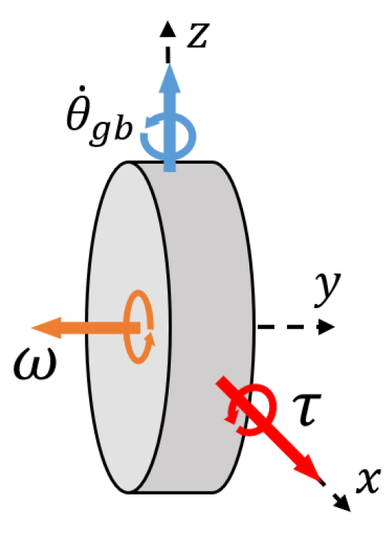
The flywheel rotates in the CMG to cause angular momentum, and torque is generated when this angular momentum is rotated by the gimbal motor. The directions of the angular momentum, the rotational angular velocity of the gimbal, and the torque from a 90 angle based on the center of mass (COM) of the flywheel are shown in Figure 2. The torque generated in the CMG can be obtained from the following equation:
τ = θ ˙ g b L = θ ˙ g b I ω
As mentioned in the Introduction, this study used a scissored-pair CMG. As shown in Figure 3, the flywheel and gimbal rotate in different directions, so the torque in the pitch direction, as an unnecessary element, is offset. Also, as shown in Equation (3), the CMG torque generated in the roll direction is doubled compared to when only one single CMG is used.
τ c m g = 2 τ c o s θ g b
Figure 3a shows the gimbal rotation when the robot tilts in the -y direction, and CMG torque is generated in the +x direction. Figure 3b shows the gimbal rotation when the robot tilts in the +y direction.

3. Dynamics and Controller Design

3.1. Notation and Assumptions

Assumptions. Unless otherwise stated, the simulations and analyses use the following operating assumptions, which reflect the CMG-based balance control:
  • No slip at the wheel–ground contact and a rigid, planar ground.
  • Rigid links and CMG assembly; gearbox backlash and structural compliance are neglected.
  • Small-angle operation about the upright, enabling first-order linearization ( | θ r | , | θ p | < 5 ) .
  • Roll–pitch decoupling near the operating region due to the scissored-pair CMG: pitch-direction torque components are canceled by symmetry and roll authority scales such as τ c m g = 2 τ cos θ g b ; the residual coupling terms in the linearized model remain below the sensor noise within the stated range.
  • Wheel actuation affects the pitch plane (forward/backward motion); roll torque is generated by the CMG; and yaw is actuated via gimbal motion (no external yaw moments).
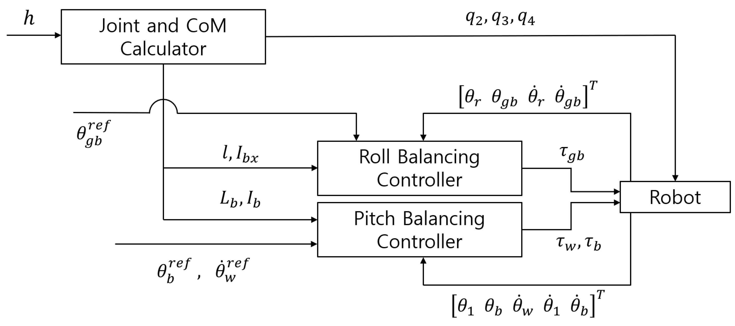
The control mechanism of the CULR is as shown in Figure 4. The pitch balancing controller performed partial feedback control, not receiving the state of θ w during the movement of the wheel.

3.2. Roll Dynamics and Balancing Controller

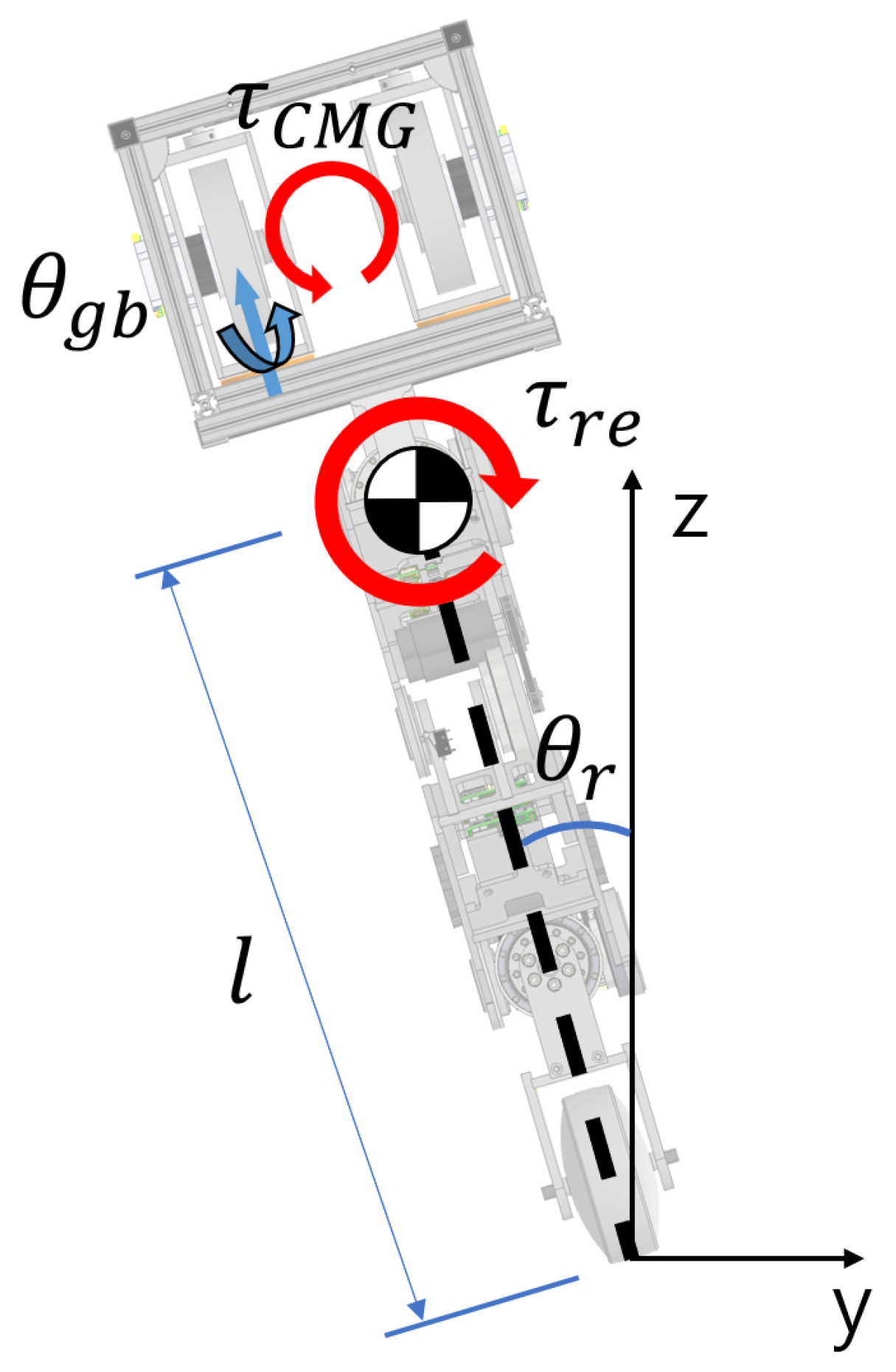
The inverted pendulum system using the CMG, unlike general cart-type systems, controls the balance with the reaction torque being applied to the robot through the torque that is generated from the CMG. The free-body diagram of the CULR in the roll direction is shown in Figure 5. The dynamics of the CULR in the roll direction were designed as follows [17]:
I b x θ ¨ r m t g l s i n θ r = Q b ( I f z + I g b z ) θ ¨ g b L θ ˙ r c o s θ g b = Q g b
Here, Q b and Q g b are external forces acting on the system and refer to the reaction torque of τ C M G and the torque τ g b that is generated from the gimbal motor, respectively.
The dynamics equation was converted into Equation (3) through a linearization process. Generalized coordinates were defined as q r = [ θ r θ g b ] T .
M r ( q r ) q ¨ r + C r ( q r , q ˙ r ) + G r ( q r ) W r u r = 0
where
M r = I b x 0 0 I f z + I g b z , C r = 2 I f y w θ ˙ g b I f y w θ ˙ g b G r = 0 m t g l θ r , W r = 0 1
Here, M r , C r , G r , and W r refer to the inertia matrix, centrifugal and Coriolis matrix, gravity matrix, and input matrix in the roll direction, respectively. u r is τ g b .
Previously, the equation of motion for τ g b was defined in the simulation framework. In this study, we extended this formulation to the hardware level by building a CMG test platform and explicitly replacing the torque input with the motor voltage input [21]. The motor torque τ ( m , g b ) is first related to the applied voltage V through the standard DC motor model:
τ ( m , g b ) = K t R m V K e θ ˙ g b m = J m θ ¨ g b m + b m θ ˙ g b m + τ g b m ,
where J m , b m , K t , K e , and R m denote the motor inertia, damping, torque constant, back-EMF constant, and winding resistance, respectively, and the superscript m indicates motor-side variables.
Because the gimbal is driven through a gear with a ratio n, the torque and rotation observed at the gimbal differ from those at the motor shaft. Incorporating this relation, the effective gimbal torque τ g b becomes
τ g b = n 2 J m θ ¨ g b n 2 K e K t R m + b m θ ˙ g b + n K t R m V .
This final expression explicitly bridges the simulation torque input τ g b and the experimental voltage input V by incorporating the motor constants, gear ratio, and back-EMF. By substituting (6) into the roll dynamics in Equation (4), we obtain the experimental state-space model used for implementation. Identified parameters and their sources are summarized in Table 2, and Figure 4 illustrates the overall control framework. This formulation clarifies the model transition between simulation and hardware.
M r m ( q r ) q ¨ r + C r m ( q r , q ˙ r ) + G r m ( q r ) W r m u r m = 0
where
M r m = I b x 0 0 I f z + I g b z + n 2 J m , C r m = 2 I f y w θ ˙ g b I f y w θ ˙ g b + n 2 ( K e K t R m + b m ) θ ˙ g b , G r m = m t g l θ r 0 ,     W r m = 0 n K t V R m
In this study, LQR control was used to control the CMG, and two state-space equations were created, because the dynamics in the simulation and the CMG test platform were different. Because the balance control in the roll direction in the simulation is mediated by the torque that is generated by the rotation of the gimbal, the state-space equation created from Equation (4) is as follows:
x r ˙ = A r x r + B r u r
where
x r = θ r θ g b θ ˙ r θ ˙ g b T , u r = τ g b A r = 0 0 1 0 0 0 0 1 m g l I b x 0 0 I f y ω I b x 0 0 I f y ω 2 ( I f z + I g b z ) 0 , B r = 0 0 0 1 2 ( I f z + I g b z )
LQR control is a method for determining the optimal control input that minimizes the cost function of the system. The cost function is as follows [22]:
J r = 0 ( x r T Q x r + u r T R u r ) d t
To compute the LQR gain K l q r for the roll input u r that minimizes the quadratic cost J r , we selected the weight matrices Q and R via an iterative tuning process to achieve the desired transient and steady-state performance.
Q = 1 0 0 0 0 10 0 0 0 0 1 0 0 0 0 1 ,   R = 1
From Equations (9) and (10), the optimal gain K l q r for LQR control was obtained as follows:
K = 68.66 3.16 17.44 1.05 T
In addition, the state-space equation to control the CMG test platform was created from Equation (7) as follows:
x r m ˙ = A r m x r m + B r m u r m
where
x r m = θ r θ g b θ ˙ r θ ˙ g b T , u r m = V A r m = 0 0 1 0 0 0 0 1 m g l I b x 0 0 I f y ω I b x 0 0 I f y ω 2 ( A r m ) 43 n 2 ( K e K t + R m b m ) ω R m ( A r m ) 44 , B r m = 0 0 0 K t n R m ( B r m ) 14 ( A r m ) 43 = ( A r m ) 44 = ( B r m ) 41 = I f z + I g b z + J m n 2
The weights Q m and R m and the optimal gain K m for LQR control in the actual model are as follows:
Q m = 50 0 0 0 0 10 0 0 0 0 50 0 0 0 0 1 ,   R m = 1
K m = 111.74 3.16 9.4 0.7 T

3.3. Pitch Dynamics and Balancing Controller

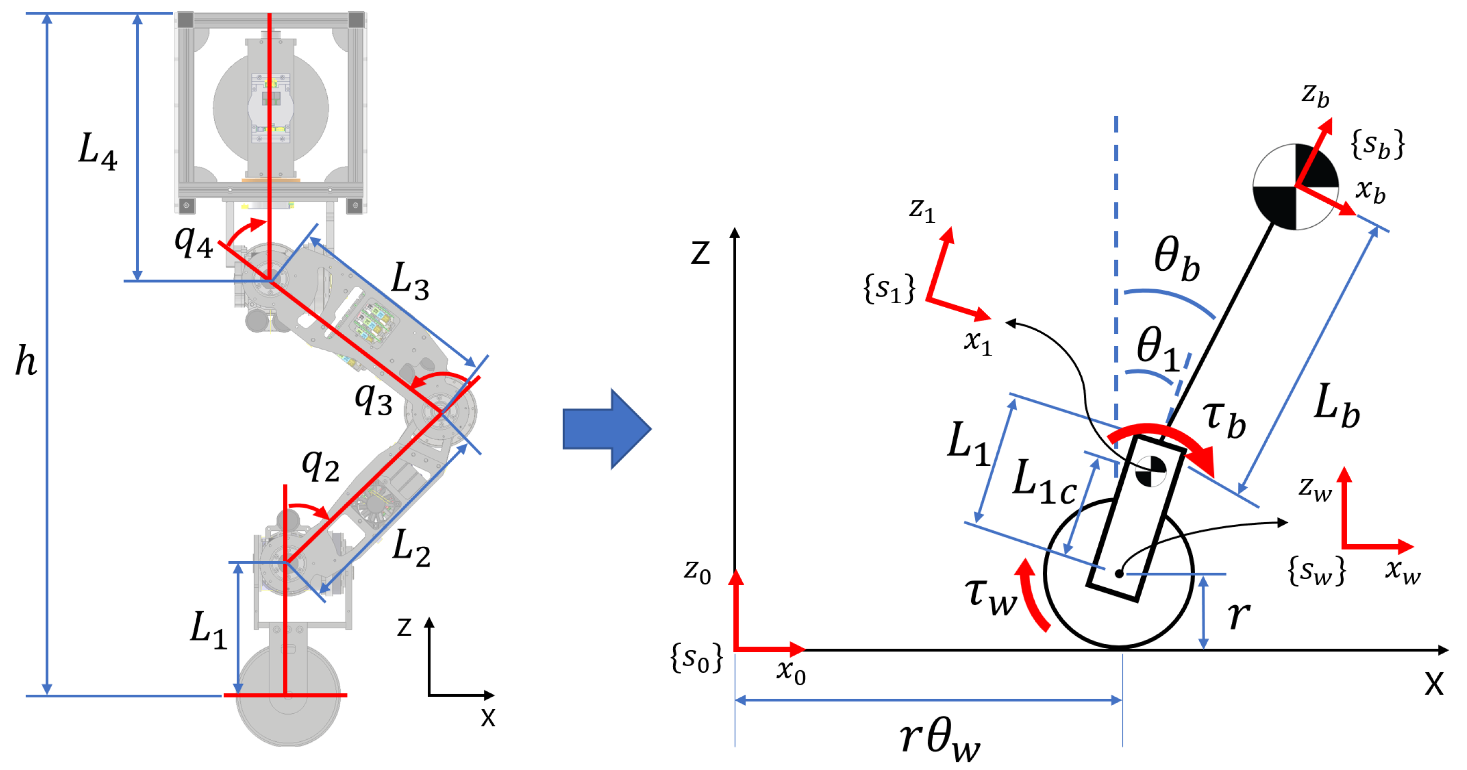
The kinematics of the legs and the double-inverted pendulum system were applied for balance control in the pitch direction of the CULR [23]. To obtain the angle of each joint, the height and the center of mass (COM) of the robot must be considered simultaneously, as shown in Equations (15)–(18). Joint q 3 rotates in the negative direction, while joints q 2 and q 4 rotate in the positive direction.
q 3 < 0 q 2 , q 4 > 0
For the convenience of calculation, the relative angle q was converted to the absolute angle θ . L 1 0 , which supports all the weight of the robot, staying vertical from the ground for stability. θ 4 was made to be 90 by the above-mentioned assumption.
θ 2 = π 2 q 2 θ 3 = π 2 q 2 + q 3 θ 4 = π 2 q 2 + q 3 + q 4 = π 2
The distance from the center of the wheel to the maximum height of the robot was set to h.
L 1 + L 2 s i n ( θ 2 ) + L 3 s i n ( θ 3 ) + L 4 s i n ( θ 4 ) = h
We added a condition in which x c o m becomes 0, because the balance of the robot had to be maintained while simultaneously solving the kinematics.
x c o m = m 2 x 2 + m 3 x 3 + m 4 x 4 m b = 0
where
x 2 = L 2 c c o s ( θ 2 ) x 3 = L 2 c o s ( θ 2 ) + L 3 c c o s ( θ 3 ) x 4 = L 2 c o s ( θ 2 ) + L 3 c o s ( θ 3 ) + L 4 c c o s ( θ 4 )
The angle of each joint to the desired height is obtained through the above kinematic conditions, and the h is 0.82∼1.077 m, considering the angle range of the joint that prevents the link from causing collisions. The h was set to 0.9 m in this study when conducting the experiments.
The knee and hip joints are fixed to control the double-inverted pendulum system. As shown in Figure 6, the links from L 2 0 to L 4 0 are assumed to be a single link, and m b indicates the mass of this link. L b and I b refer to the distance from the COM to the ankle joint and the inertia moment, respectively. The inclination angle, θ b , is defined as follows:
θ b = θ 1 + Δ q 2
Here, Δ q 2 is the amount of change in q 2 . The Lagrangian method was used to design the pitch dynamics of the CULR. In Figure 6, s 0 is the reference coordinate system, and s w , s 1 , and s b are coordinate systems located at the COM of the wheel, the COM of the link L 1 0 , and the COM of the link L b 0 , respectively. The following position vectors can be obtained through transposition and rotation:
s w = [ r θ w   0   r ] T s 1 = s w + R o t ( y , θ 1 ) [ 0   0   L 1 c ] T s b = s w + R o t ( y , θ 1 ) [ 0   0   L 1 ] T + R o t ( y , θ b ) [ 0   0   L b ] T
The kinetic energy T and potential energy V of the system were obtained by referring to the free-body diagram and the position vector of each coordinate system. T can be divided into kinetic energy T t r a n s for translational motion and kinetic energy T r o t for rotational motion.
T t r a n s = 1 2 ( m w ( s ˙ w ) 2 + m 1 ( s ˙ 1 ) 2 + m 2 ( s ˙ 2 ) 2 ) T r o t = 1 2 ( I w ( θ ˙ w ) 2 + I 1 ( θ ˙ 1 ) 2 + I 2 ( θ ˙ 2 ) 2 ) V = m w g r + m 1 g L 1 c c o s θ 1 + m b g ( L 1 c o s θ 1 + L b c o s θ b )
The Lagrangian, which is the difference between the potential energy and the kinetic energy, is defined as follows:
L = T t r a n s + T r o t + V
Generalized coordinates are defined as q p = [ θ w θ 1 θ w ] T . From the Lagrangian obtained above, the following Lagrange’s equation can be obtained:
d d x L θ ˙ w L θ w = Q w d d x L θ ˙ 1 L θ 1 = Q 1 d d x L θ ˙ b L θ b = Q b
Here, Q w , Q 1 , and Q b are generalized forces acting on the system. Specifically, Q w = τ w and Q b = τ b denote the motor torques at the wheel and ankle joints, respectively, while Q 1 = τ w + τ b represents their sum acting on the body with the opposite sign. Equation (23) can be linearized and written as follows:
M p ( q p ) q ¨ p + C p ( q p , q ˙ p ) + G p ( q p ) W p u p = 0
where
M p = I w + m t r 2 r ( m b L 1 + m 1 L 1 c ) 2 m b L b r r ( m b L 1 + m 1 L 1 c ) I 1 + m b L 1 2 + m 1 L 1 c 2 m b L 1 L b 2 m b L b r m b L 1 L b I b + m b L b 2 C p = 0 0 0 , G p = 0 ( m b L 1 + m 1 L 1 c ) g θ 1 m b L b g θ b , W p = 1 1 1 1 0 1
Here, M p , C p , G p , and W p refer to the inertia matrix, centrifugal and Coriolis matrix, gravity matrix, and input matrix in the pitch direction, respectively, and u p is [ τ w τ b ] T . τ w indicates the torque in the wheel, and τ b indicates the torque in the ankle joint.
We used MPC for pitch balance control. MPC has the advantage of predicting the state and control input using a detailed model of the robot and finding the optimal control input using the constraints and the cost function. In this case, constraints can be set as equality constraints or inequality constraints. However, it also has a disadvantage of poor real-time control performance, because it requires information about the future that causes a delay in the system. We used discrete-time model predictive control (DMPC) to compensate for this disadvantage. To use DMPC, the equation of motion was converted into a continuous time equation of state as follows:
x ˙ p = A p x p + B p u p y p = C p x p
where
x p = [ θ w       θ 1       θ b       θ w ˙       θ 1 ˙       θ b ˙ ] T , u p = [ τ w       τ b ] T A p = 0 0 0 1 0 0 0 0 0 0 1 0 0 0 0 0 0 1 0 856.8 29.13 0 0 0 0 582.09 184.55 0 0 0 0 72.19 77.48 0 0 0 B p = 0 0 0 0 0 0 83.14 37.08 38.93 5.48 1.65 3.08 ,   C p = I 6 × 6
Equation (25) was converted into a discrete-time state-space equation. The sampling time for discretization was 0.017 s, and the prediction horizon was set to 80.
x ( k + 1 ) = A d x ( k ) + B d u ( k ) y ( k ) = C d x ( k )
Here, k refers to a specific time step. The cost function, J p , was defined as shown in Equation (27) to minimize the sum of squares of the state, and no additional constraints were specified.
J p = m i n ( θ 1 2 + 5500 ( θ b r e f θ b ) 2 + 1.5 ( θ ˙ w r e f θ ˙ w ) 2 + θ ˙ 1 2 + θ ˙ b 2 )
Here, θ b r e f and θ ˙ w r e f indicate the desired data of θ b and θ ˙ w , respectively. For real-time execution, the DMPC was implemented with ( n x = 6 , n u = 2 ) , T s = 17 ms , and N = 80 . Using a sparse QP solver, the average solve time left a more than 30% timing margin on our target platform.

3.4. Rotation Control in the Yaw Direction

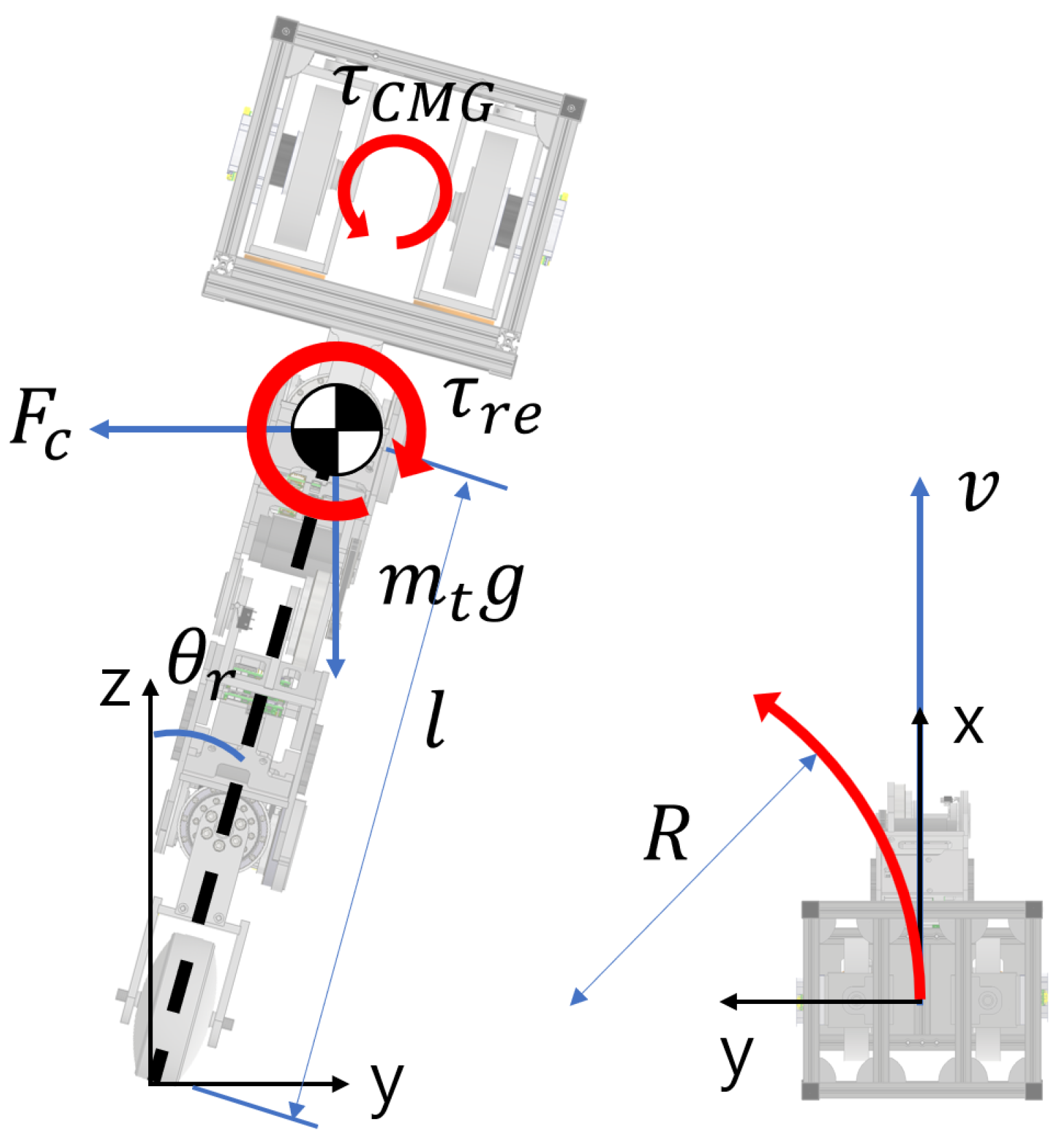
When an existing wheeled–legged robot rotates in the yaw direction, it is possible to control various rotations, such as forward/backward movement, stationary rotation, and circular running through differential drive control. However, the unicycle–legged robot presented in this study has one wheel, so it cannot use the differential drive control that is available in existing wheeled–legged robots. Therefore, a method using the torque generated from the CMG was devised to control the rotation of the CULR in the yaw direction. The free-body diagram of the CULR in the yaw direction is shown in Figure 7.
When the angle of the gimbal of the CMG is rotated by θ g b r e f , the torque τ C M G that is generated from the CMG causes the reaction torque τ r e , which is only different from τ C M G in the direction toward the robot. τ r e causes the robot to tilt by as much as τ r , and at the same time, the robot moving at speed v rotates with radius R. The centrifugal force F c generated at this time is as follows:
F c = m t v 2 R
The torque generated by F c to the robot is as follows:
τ c = F c l c o s θ r = m t g l s i n θ r
Equations (28) and (29) are organized for R as follows:
R = v 2 g t a n θ r
The larger the reaction torque τ r e is, the larger the tilt angle θ r of the robot is, so the following proportional expression holds:
R 1 θ r 1 τ r e
The physical principles and design procedure of the yaw control are as follows: The CMG produces body torques via the time derivative of the flywheel’s angular momentum H :
τ = H ˙ = Ω g × H .
In other words, actuating the gimbal to rotate in the direction of the angular momentum vector causes a precession effect that generates body torques, including the yaw component [24]. For the scissored-pair geometry, the mapping from the gimbal rate to yaw torque is
τ y = e z J y ( θ gb ) θ ˙ gb H , H = H .
Here, J y ( θ gb ) follows from geometric symmetry: pitch–direction components are canceled, while the yaw component is reinforced. Because H scales with the flywheel speed, the effective yaw torque is determined jointly by the gimbal command and the flywheel speed.
The yaw-axis dynamics are approximated in the small-angle/low-rate regime as
I y ψ ¨ + b y ψ ˙ = τ y .
This second-order linear model compactly captures inertial and viscous effects over the operating range; within the control framework, it is arranged so as not to interfere with the closed-loop roll–pitch subsystems (see Table 2 for the parameter definitions).
We use a velocity-tracking controller:
θ ˙ gb = K y ( ψ ˙ d ψ ˙ ) + K i ( ψ ˙ d ψ ˙ ) d t .
The gains K y and K i are chosen to stabilize the transient response and eliminate steady-state error. In implementation, we include the gimbal rate/angle saturation, integral anti-windup, and low-pass filtering (e.g., of the z-axis gyroscope) to ensure numerical robustness and constraint satisfaction [25]. The relevant parameters are summarized in Table 2, and the overall signal flow is outlined by the control framework in Figure 4.

4. Simulation

4.1. Self-Balancing Simulation

To verify the roll and pitch balancing controllers in the Gazebo simulation, we set the initial tilt angle of the roll and pitch system, θ r , θ 1 , and θ b , to 10 . We set the flywheel rotational speed to 5000 RPM to generate τ CMG . Demonstration videos are available as Videos S1 and S2 in the Supplementary Materials. Figure 8a shows that the roll control and pitch control take approximately 2 s and 1.5 s to converge to a steady state from a specified initial tilt angle.
We conducted an experiment to verify the CULR’s ability to overcome external disturbance and applied a force of 20 N in the roll direction and pitch direction, respectively, at a height of 0.914 m from the surface. As shown in Figure 8b, θ r , θ 1 , and θ b tilted by approximately 1 . 5 , 12 , and 8 , respectively, when the disturbance was applied. It took 2.5 s and 1.8 s for the roll and pitch system, respectively, to converge to a steady state. Additional videos of the disturbance tests are available as Videos S3 and S4 in the Supplementary Materials.

4.2. Driving Control Simulation in the X Direction

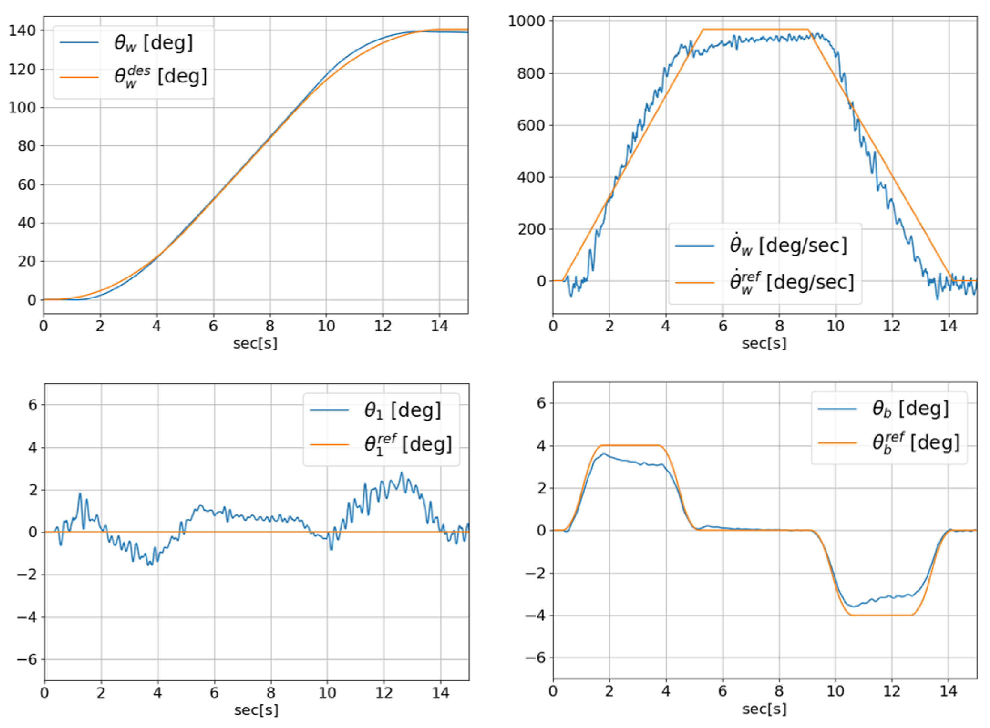
Driving is the most fundamental and important aspect, because it can take advantage of the mobility of the wheeled–legged robot. A trapezoidal velocity profile was used to test the x-directional velocity control of the CULR, and a trajectory capable of producing a velocity of 1.16 m/s was assigned to θ ˙ w . When driving begins, the wheel immediately moves backward due to the nature of the inverted pendulum system. To minimize such wheel movement, we input the desired angle in θ b and used a gentle desired trajectory to prevent rapid angle changes. As shown in Figure 9, we confirmed that θ w and θ b are controlled along the desired trajectory and that θ 1 with the desired angle of 0 is maintained at approximately ± 2 . A demonstration video is available as Video S5. In addition, we verified that the CULR can pass through a narrow space with a width of 0.15 m. A demonstration video is available as Video S6.

4.3. Obstacle Avoidance Simulation

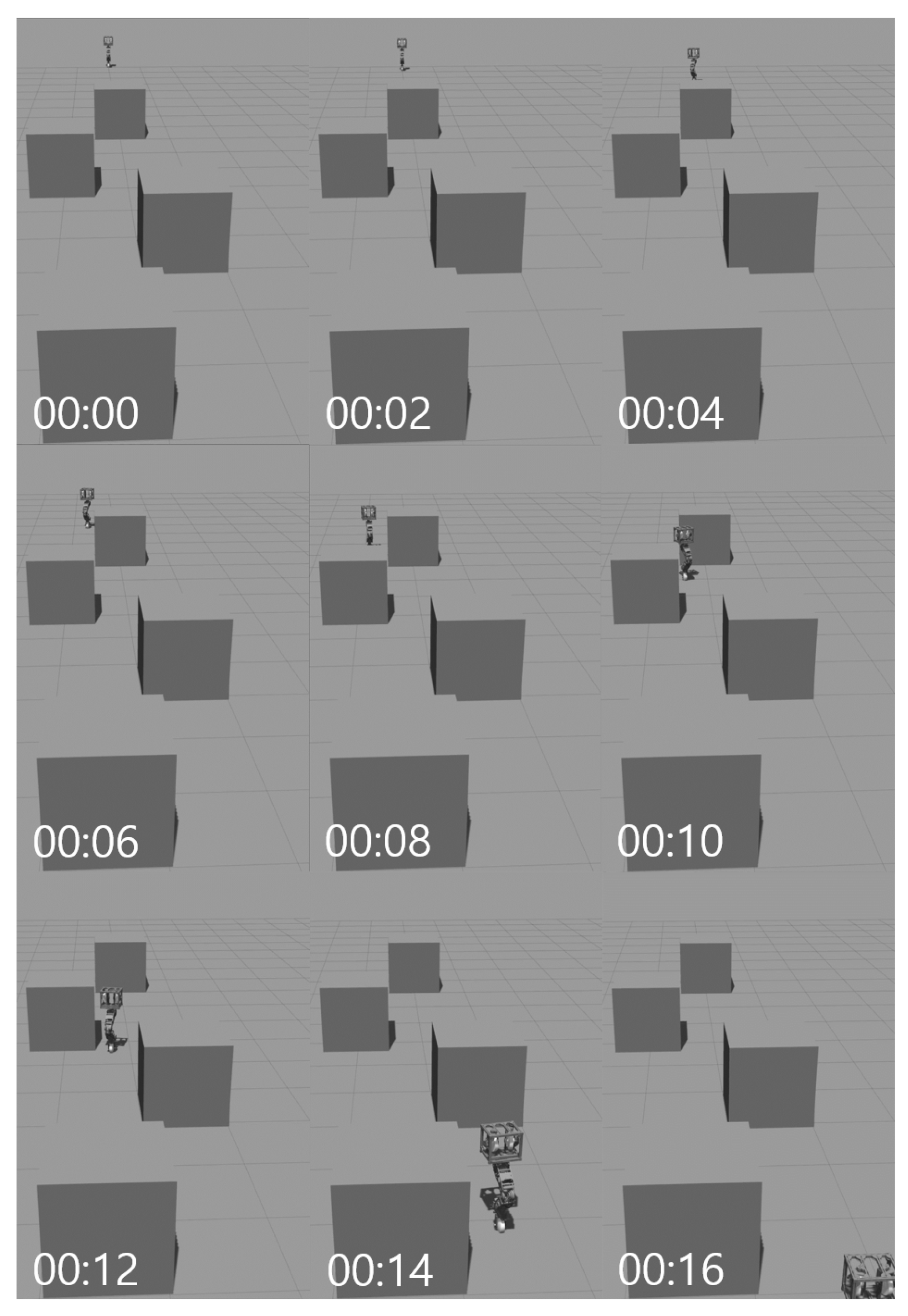
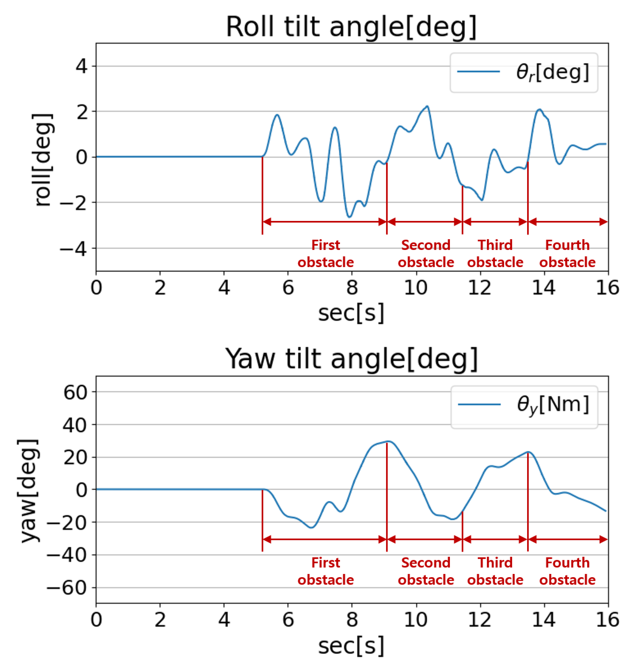
In order to verify the ability of the CULR to avoid obstacles, four boxes measuring 1 m × 1 m × 1 m were placed in random positions and simulated to avoid the obstacles. We used the joystick controller to control the robot and verified that the robot avoided the obstacle properly so that θ r did not deviate from ± 3 while avoiding the obstacle. A snapshot of the simulation can be seen in Figure 10, and the graph of the simulation is shown in Figure 11. A demonstration video is available as Video S7 in the Supplementary Materials.

5. Experiment

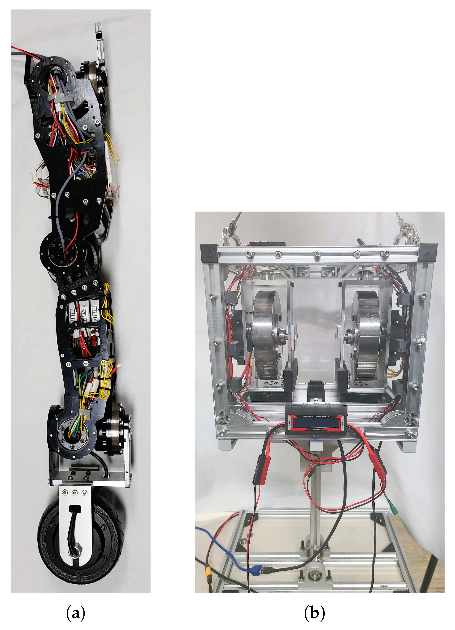
Before controlling the actual model of the CULR, we built a CMG test platform to validate the balance control, as shown in Figure 12b. To control the CMG, we used VESCular6 [26,27], a custom-designed and -built BLDC motor controller developed in our laboratory, together with an RMD-x6 BLDC motor (Suzhou Micro Actuator Technology Co., Ltd., Kunshan, China) for the gimbal motor and a Prodrive v2 5050 BLDC motor (Prodrive Technologies B.V., Eindhoven, The Netherlands) for the spin motor. Bosch’s BMX160 (Bosch Sensortec GmbH, Reutlingen, Germany), built into VESCular6 (Open Robot, Inc., Republic of Korea), was used as an IMU to receive the platform states.
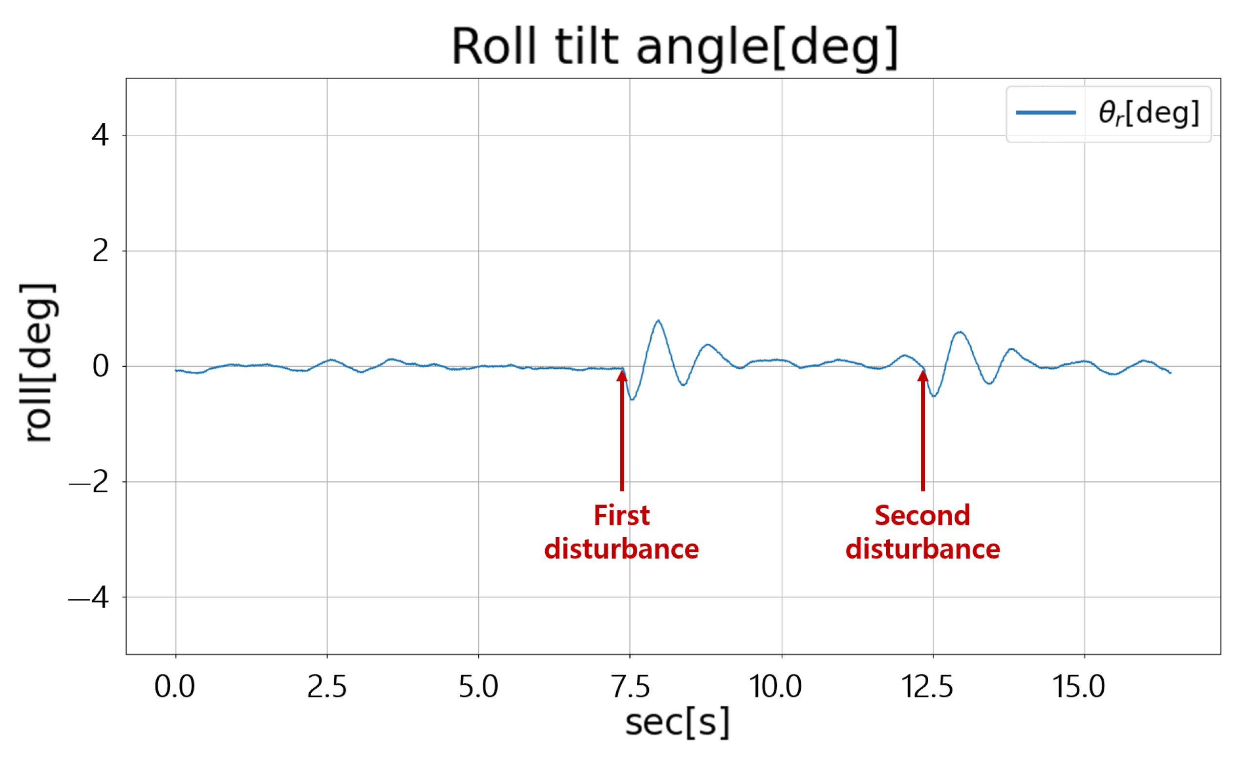
Unlike in the simulation, because a test platform was used, the total mass and moment of inertia were reduced. Because a τ C M G was not required as in the simulation, the rotational speed of the flywheel was set to 1500 RPM. Equation (12) was used for the state-space equation. As shown in Figure 13, when two disturbances were applied, it was confirmed that θ r converged to a steady state after about 2 s, and that control was achieved within ± 1 . A demonstration video is available as Video S8 in the Supplementary Materials.

6. Limitations and Practical Considerations

Our approach still has several limitations. First, the system can be affected by gyroscopic coupling near gimbal singularities, as well as by actuator saturation or overheating during aggressive maneuvers. Structural flexibility of the hardware and delays in sensing may also cause performance loss. Second, the power budget is limited, and there is a trade-off between torque output and energy efficiency. In addition, the MPC controller requires a balance between computation time and performance, because a longer horizon improves the control quality but increases the computational load. To handle these issues, we consider fallback controllers such as LQR when computation resources are limited. Finally, making the controller more robust to contact-model uncertainty is an important direction for future work.

7. Conclusions

In this paper, we propose the development of a unicycle–legged robot with a CMG applied and a control system that is separated in the roll and pitch directions. Existing wheeled–legged robots have excellent stability and are capable of overcoming various obstacles, such as stairs or rough terrain, but have limitations in movement in narrow terrain or environments. To solve this problem, a unicycle–legged robot was developed, a scissored-pair CMG was mounted to control the balance in the roll direction, and the robot was assumed to be a double-inverted pendulum to control the balance in the pitch direction. The designed controller was verified in a Gazebo simulation, showing robust balance control against initial inclination and disturbance and the ability to pass through narrow obstacles, unlike existing wheeled–legged robots. In addition, it was confirmed that the robot overcomes complex obstacles through rotation control in the yaw direction using the torque that is generated from the CMG. The CMG test platform was built to verify the controller in the actual model, which was verified in the simulation, and it was confirmed that the balance control was achieved within ± 1 .
In future work, as illustrated in Figure 12a,b, we will integrate the unicycle–leg and CMG assemblies into the complete CULR and evaluate the integrated system in real-world experiments using the controller validated in the simulation. In this study, the unicycle–legged robot was assumed to be a double-inverted pendulum. Wheeled–legged robots, however, use their legs for more dynamic control or use an active suspension system for maximum stability and flexibility. In order to apply this to the CULR, we plan to use whole-body control later. Furthermore, it is expected to be a versatile platform for path planning and navigation using vision sensors and lidar in a narrow and complex environment.

Supplementary Materials

The following supporting videos are available online: Video S1: Self-balancing simulation in roll direction: https://youtu.be/lLrbA423Wxw; Video S2: Self-balancing simulation in pitch direction: https://youtu.be/TFpFetU5Uu8; Video S3: External disturbance simulation in roll direction: https://youtu.be/W7moJYfZeOc; Video S4: External disturbance simulation in pitch direction: https://youtu.be/Row1iCLvfcw; Video S5: X-directional driving control simulation: https://youtu.be/CsfpCKf0Gq0; Video S6: Narrow passage simulation: https://youtu.be/ZiYqfOUxYBg; Video S7: Obstacle avoidance simulation: https://youtu.be/Ur_DcQc9pPs; Video S8: CMG test platform experiment: https://youtu.be/G6L0HWNUN-8 (accessed on 13 September 2025).

Author Contributions

Conceptualization, S.S. and D.C.; methodology, S.S.; software, S.S. and M.C.; validation, S.A. and S.H.; formal analysis, D.K.; investigation, D.C.; resources, S.S.; data curation, S.S. and S.A.; writing—original draft preparation, S.S.; writing—review and editing, D.C.; visualization, S.S. and M.C.; supervision, D.C.; project administration, D.C.; funding acquisition, D.C. All authors have read and agreed to the published version of the manuscript.

Funding

This work was supported by the Robot Industry Core Technology Development Project (No. RS-2024-00444294, Development of Core Technologies for a Multi-Drive Robot Platform Capable of Performing Tasks in Military Areas with Uneven Terrains) funded By the Ministry of Trade, Industry Energy (MOTIE, Korea).

Institutional Review Board Statement

Not applicable.

Informed Consent Statement

Not applicable.

Data Availability Statement

The original contributions presented in this study are included in the article; further inquiries can be directed to the corresponding author.

Conflicts of Interest

Author Seungchul Shin was employed by the company HL Klemove, Next M, author Minjun Choi was employed by the company Neuromeka, Econet Center, and author Seongmin Ahn was employed by the company DH AUTOEYE, WOOMI NEWV. The remaining authors declare that the research was conducted in the absence of any commercial or financial relationships that could be construed as a potential conflict of interest.

Abbreviations

The following abbreviations are used in this manuscript:
CMGControl Moment Gyroscope
LQRLinear Quadratic Regulator
MPCModel Predictive Control
DMPCDiscrete Model Predictive Control
W-SLIPWheeled–Spring-Loaded Inverted Pendulum
CULRCMG Unicycle–Legged Robot
COMCenter of Mass
EMFElectromotive Force

References

  1. Schwarz, M.; Rodehutskors, T.; Droeschel, D.; Behnke, S. Hybrid driving–stepping locomotion with the wheeled-legged robot Momaro. In Proceedings of the 2016 IEEE International Conference on Robotics and Automation (ICRA), Stockholm, Sweden, 16–21 May 2016; pp. 5589–5596. [Google Scholar]
  2. Schwarz, M.; Rodehutskors, T.; Droeschel, D.; Behnke, S. NimbRo Rescue: Solving disaster-response tasks through mobile manipulation robot Momaro. J. Field Robot. 2018, 35, 400–425. [Google Scholar] [CrossRef]
  3. Bjelonic, M.; Bellicoso, C.D.; Jenelten, F.; Hutter, M. Design principles for wheeled-legged robots. IEEE Robot. Autom. Lett. 2019, 4, 315–322. [Google Scholar]
  4. Bjelonic, M.; Jenelten, F.; Bellicoso, C.D.; Hutter, M. Whole-body MPC and online gait sequence generation for wheeled-legged robots. In Proceedings of the 2021 IEEE/RSJ International Conference on Intelligent Robots and Systems (IROS), Prague, Czech Republic, 27 September–1 October 2021; pp. 7080–7087. [Google Scholar]
  5. Cordes, F.; Dettmann, A.; Kirchner, F. Locomotion modes for a hybrid wheeled-leg planetary rover. In Proceedings of the 2011 IEEE International Conference on Robotics and Biomimetics (ROBIO), Phuket, Thailand, 7–11 December 2011; pp. 2581–2586. [Google Scholar]
  6. Cordes, F.; Kirchner, F.; Babu, A. Design and field testing of a rover with an actively articulated suspension system (SherpaTT). J. Field Robot. 2018, 35, 1101–1124. [Google Scholar] [CrossRef]
  7. Xin, S.; Vijayakumar, S. Online dynamic motion planning and control for wheeled biped robots. In Proceedings of the 2020 IEEE/RSJ International Conference on Intelligent Robots and Systems (IROS), Las Vegas, NV, USA, 25–29 October 2020; pp. 3892–3899. [Google Scholar]
  8. Chen, J.; Gao, F.; Huang, C.; Zhao, J. Whole-body motion planning for a six-legged robot walking on rugged terrain. Appl. Sci. 2019, 9, 5284. [Google Scholar] [CrossRef]
  9. Chen, H.; Wang, B.; Hong, Z.; Shen, C.; Wensing, P.M.; Zhang, W. Underactuated motion planning and control for jumping with wheeled-bipedal robots. IEEE Robot. Autom. Lett. 2021, 6, 747–754. [Google Scholar] [CrossRef]
  10. Semini, C.; Focchi, M.; Featherstone, R.; Caldwell, D.G. Quadrupedal locomotion over rough terrain: Models and experiments. Int. J. Robot. Res. 2017, 36, 170–187. [Google Scholar]
  11. Sheng, Z.; Yamafuji, K. Postural stability of a human riding a unicycle and its emulation by a robot. IEEE Trans. Robot. Autom. 1997, 13, 709–720. [Google Scholar] [CrossRef]
  12. Han, S.I.; Lee, J.M. Balancing and velocity control of a unicycle robot based on the dynamic model. IEEE Trans. Ind. Electron. 2015, 62, 405–413. [Google Scholar] [CrossRef]
  13. Lee, J.-O.; Han, S.-I.; Lee, J.-M. Decoupled dynamic control for pitch and roll axes of the unicycle robot. IEEE Trans. Ind. Electron. 2013, 60, 3814–3822. [Google Scholar] [CrossRef]
  14. Shim, Y.K.; Ha, M.S.; Jung, S. Roll control of a novel single line play robot by controlling air pressure of ducted fans. In Proceedings of the 2012 IEEE International Symposium on Industrial Electronics (ISIE), Hangzhou, China, 28–31 May 2012; pp. 937–942. [Google Scholar]
  15. Kawak, B.J. Development of a low-cost, low micro-vibration CMG for small agile satellite applications. Acta Astronaut. 2017, 131, 113–122. [Google Scholar] [CrossRef]
  16. Kojima, H.; Nakamura, R.; Keshtkar, S. Steering control law for double-gimbal scissored-pair CMG. Adv. Space Res. 2020, 66, 771–784. [Google Scholar] [CrossRef]
  17. Park, S.H.; Yi, S.Y. Active balancing control for unmanned bicycle using scissored-pair control moment gyroscope. Int. J. Control Autom. Syst. 2020, 18, 217–224. [Google Scholar] [CrossRef]
  18. Jin, H.; Wang, T.; Yu, F.; Zhu, Y.; Zhao, J.; Lee, J. Unicycle robot stabilized by the effect of gyroscopic precession and its control realization based on centrifugal force compensation. IEEE/ASME Trans. Mechatron. 2016, 21, 2737–2745. [Google Scholar] [CrossRef]
  19. Park, I.W.; Kim, J.Y.; Lee, J.; Oh, J.H. Mechanical design of the humanoid robot platform, HUBO. Adv. Robot. 2007, 21, 1305–1322. [Google Scholar] [CrossRef]
  20. Lim, J.; Lee, I.; Sim, O.; Joe, H.; Kim, I.; Lee, J.; Oh, J.H. Robot system of DRC-HUBO+ and control strategy of Team KAIST in DARPA Robotics Challenge Finals. J. Field Robot. 2017, 34, 1359–1382. [Google Scholar] [CrossRef]
  21. Choi, D.; Oh, J.H. Active suspension for a rapid mobile robot using Cartesian computed torque control. J. Intell. Robot. Syst. 2015, 79, 221–235. [Google Scholar] [CrossRef]
  22. Choi, D. Model predictive control of autonomous delivery robot with non-minimum phase characteristic. Int. J. Precis. Eng. Manuf. 2020, 21, 883–894. [Google Scholar] [CrossRef]
  23. Zhang, C.; Liu, T.; Song, S.; Meng, M.Q.H. System design and balance control of a bipedal leg-wheeled robot. In Proceedings of the 2019 IEEE International Conference on Robotics and Biomimetics (ROBIO), Dali, China, 6–8 December 2019; pp. 1869–1874. [Google Scholar]
  24. Wertz, J.R. (Ed.) Spacecraft Attitude Determination and Control; Astrophysics and Space Science Library; Springer: Dordrecht, The Netherlands, 2012; Volume 73. [Google Scholar]
  25. Yang, Y.; Kim, S.; Lee, K.; Leeghim, H. Disturbance robust attitude stabilization of multirotors with control moment gyros. Sensors 2024, 24, 8212. [Google Scholar] [CrossRef] [PubMed]
  26. Choi, D. VESCular6: An Open-Source Motor Controller Framework for Robotics (Documentation). GitBook. Available online: https://dongilc.gitbook.io/ (accessed on 19 September 2025).
  27. Choi, D. Development of open-source motor controller framework for robotic applications. IEEE Access 2020, 8, 14134–14145. [Google Scholar] [CrossRef]
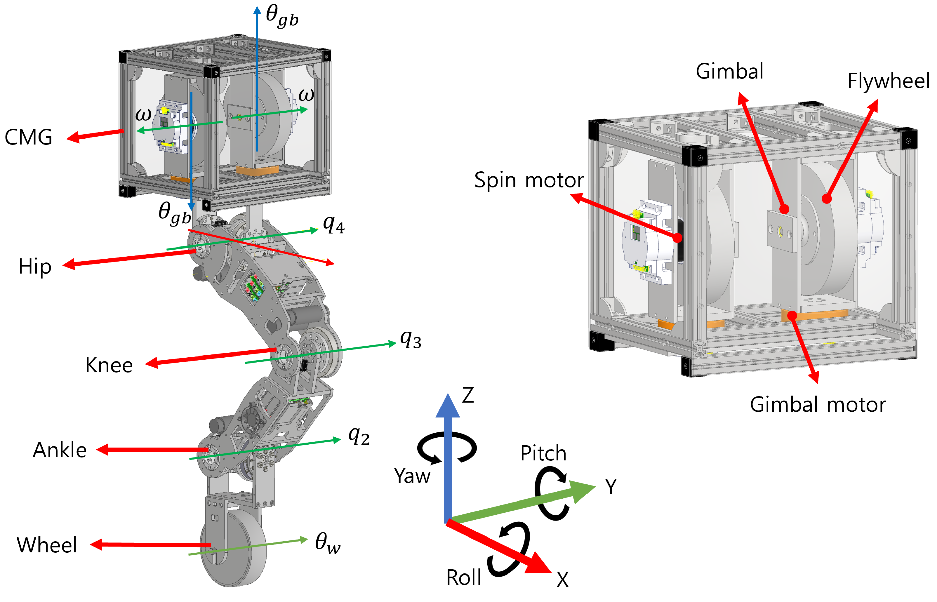
Figure 1. Three-dimensional modeling of CULR and CMG.
Machines 13 00937 g001
Figure 2. Free-body diagram of single CMG.
Machines 13 00937 g002
Figure 3. Free-body diagrams of the scissored-pair CMG.
Machines 13 00937 g003
Figure 4. Control framework of CULR.
Machines 13 00937 g004
Figure 5. Free-body diagram of CULR in roll direction.
Machines 13 00937 g005
Figure 6. Free-body diagram of CULR in pitch direction.
Machines 13 00937 g006
Figure 7. Rotating motion of CULR in yaw direction.
Machines 13 00937 g007
Figure 8. Self-balancing of the CULR. (a) Roll and pitch tilt angles during recovery from an initial 10 tilt. (b) Roll and pitch tilt angles under an external disturbance of 20 N , applied at a height of 0.914 m .
Machines 13 00937 g008
Figure 9. Desired and measured states of CULR with velocity control; see Video S5 in the Supplementary Materials.
Machines 13 00937 g009
Figure 10. Snapshot of a simulation of obstacle avoidance; see Video S7 in the Supplementary Materials.
Machines 13 00937 g010
Figure 11. Roll and yaw tilt angle of an obstacle avoidance simulation.
Machines 13 00937 g011
Figure 12. Real prototypes of the CULR. (a) Unicycle–leg part. (b) CMG test platform.
Machines 13 00937 g012
Figure 13. Roll tilt angle of CMG test platform; see Video S8 in the Supplementary Materials.
Machines 13 00937 g013
Table 1. Specifications of CULR.
Degrees of FreedomCMG4 DOF
Hip2 DOF
Knee1 DOF
Ankle2 DOF
Wheel1 DOF
Total10 DOF
Platform Size290 mm × 250 mm × 1146 mm
(Maximum height)
Wheel Size5.5 Inch
Weight25.007 kg
Flywheel Mass3.73 kg
Height0.889∼1.146 m
Table 2. System parameters of the CULR. Scalars are italic; acronym subscripts are roman.
Symbol Definition Unit
θ r roll angle rad
θ p pitch angle rad
ψ yaw angle rad
θ g b gimbal angle rad
θ w wheel angle rad
q i relative angle of the ith link rad
H flywheel angular momentum (vector) N · m · s
Hmagnitude of H N · m · s
Ω g gimbal angular velocity (vector) rad / s
τ c m g CMG torque about body N · m
Vmotor drive voltage (gimbal) V
nmotor gear ratio
m t total mass of the robot kg
m i mass of the ith link kg
J m motor rotor inertia kg · m 2
I b x body moment of inertia about the x-axis kg · m 2
I w wheel moment of inertia about the y-axis kg · m 2
I f y , I f z flywheel moments of inertia about y and z axes kg · m 2
I gb z gimbal moment of inertia about the z-axis kg · m 2
L i length of the ith link m
L i c distance from joint of link i to its COM m
L i 0 link vector of length L i (base frame 0) m
rwheel radius m
ldistance from ground to COM m
x COM , z COM distance from wheel center to COM along x/z axes m
K t motor torque constant N · m / A
K e motor back-EMF constant V · s / rad
R m motor winding resistance Ω
b m motor viscous damping coefficient N · m · s / rad
Index:  i { 1 , 2 , 3 , 4 } denotes (1) wheel–ankle, (2) ankle–knee, (3) knee–hip, (4) hip–CMG.
Disclaimer/Publisher’s Note: The statements, opinions and data contained in all publications are solely those of the individual author(s) and contributor(s) and not of MDPI and/or the editor(s). MDPI and/or the editor(s) disclaim responsibility for any injury to people or property resulting from any ideas, methods, instructions or products referred to in the content.