
Review on Key Development of Magnetic Bearings


Abstract
:1. Introduction
2. Classification of Magnetic Bearings
2.1. Suction Magnetic Bearing
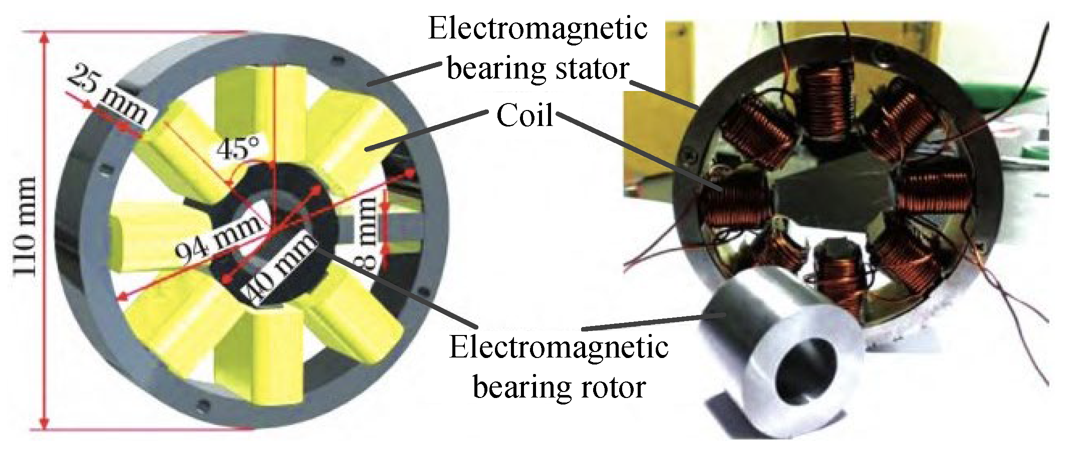
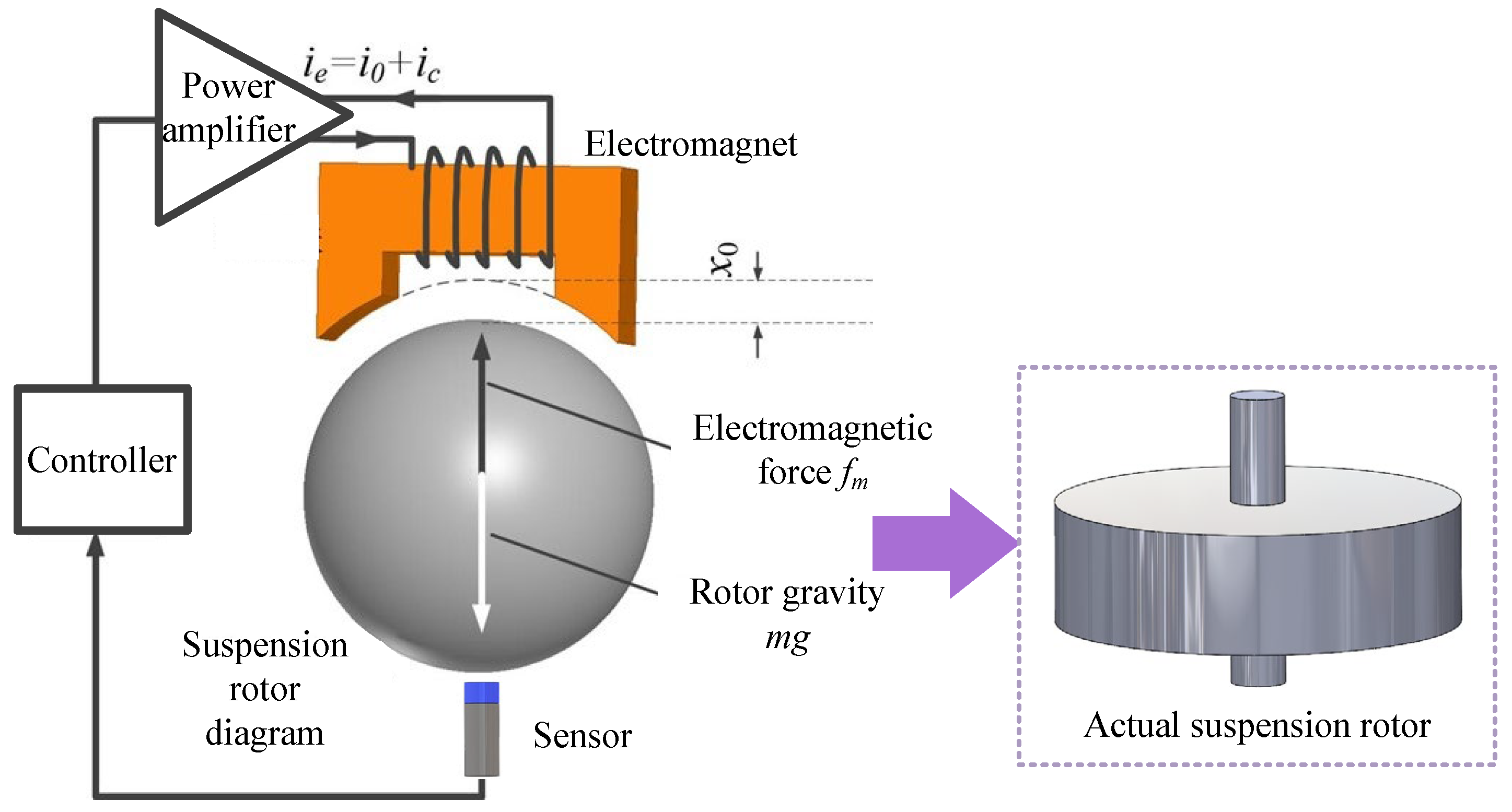
2.1.1. Electromagnetic (Active) Magnetic Bearings (AMB)
- (1)
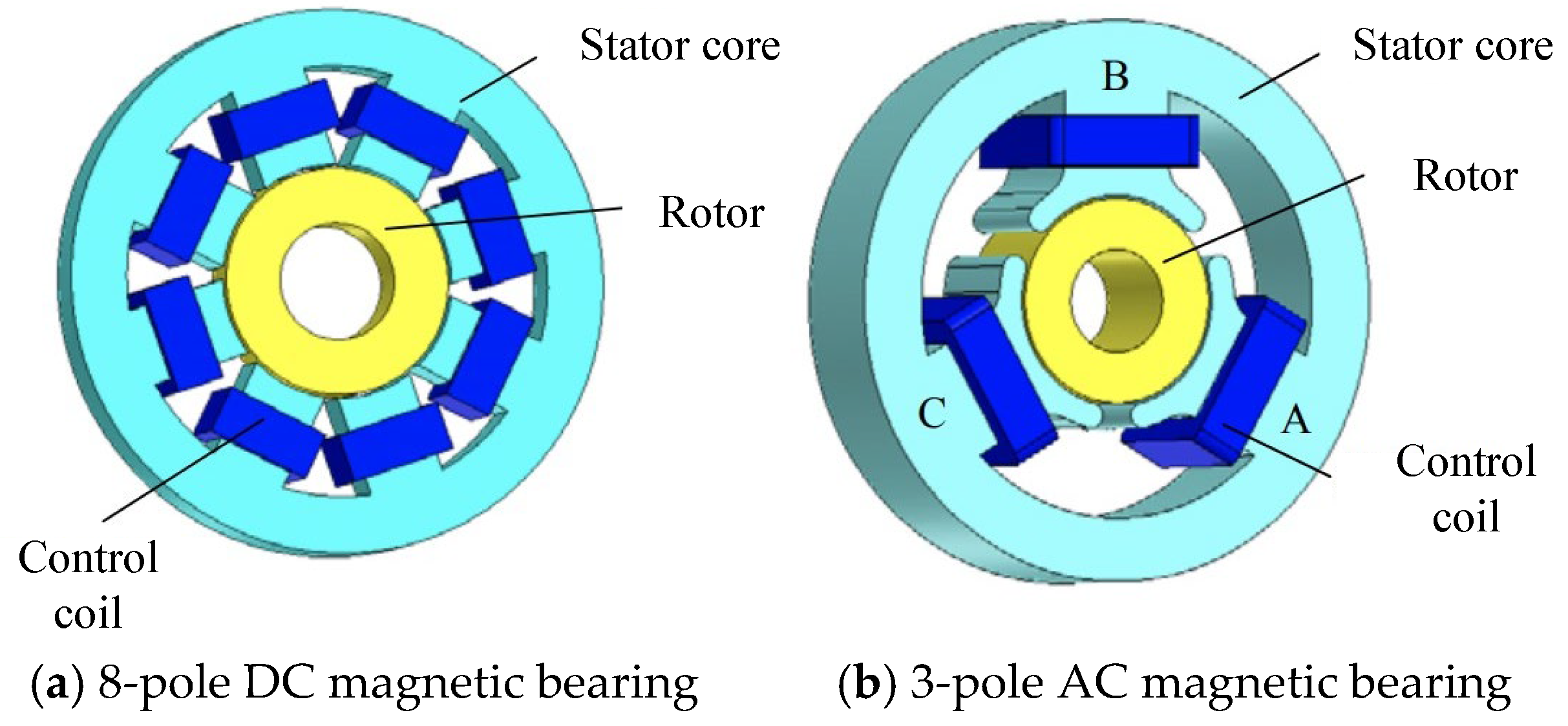
- DC active magnetic bearing
- (2)
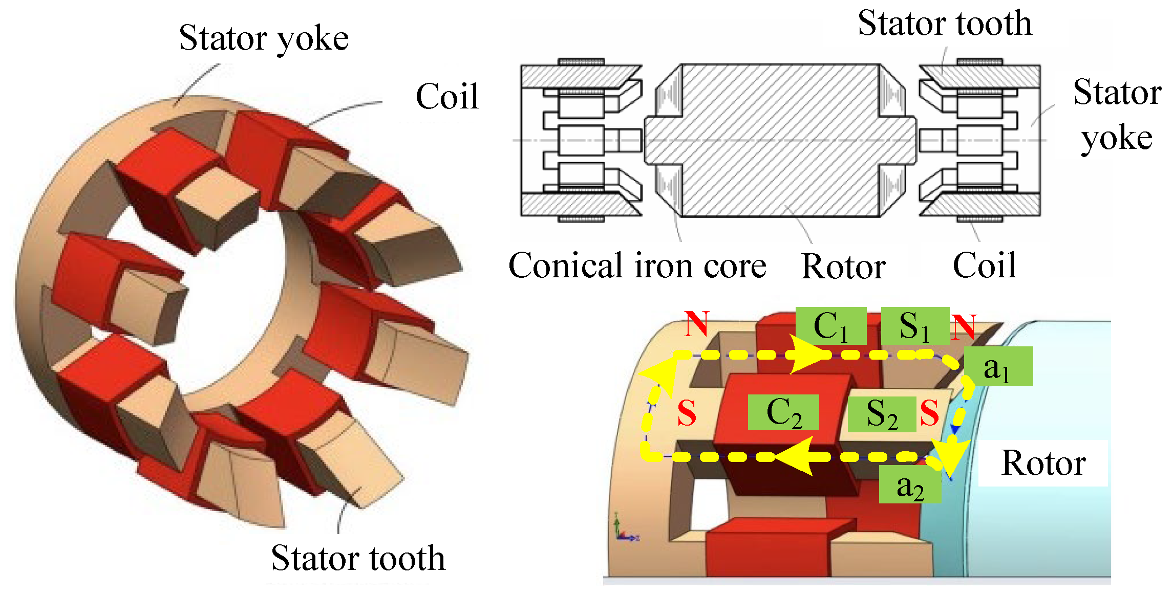
- AC active magnetic bearing
2.1.2. Hybrid Magnetic Bearings (HMB)
2.1.3. Passive Magnetic Bearings (PMB)
2.2. Repulsive Magnetic Bearings
2.2.1. Passive Magnetic Bearings (PMB)
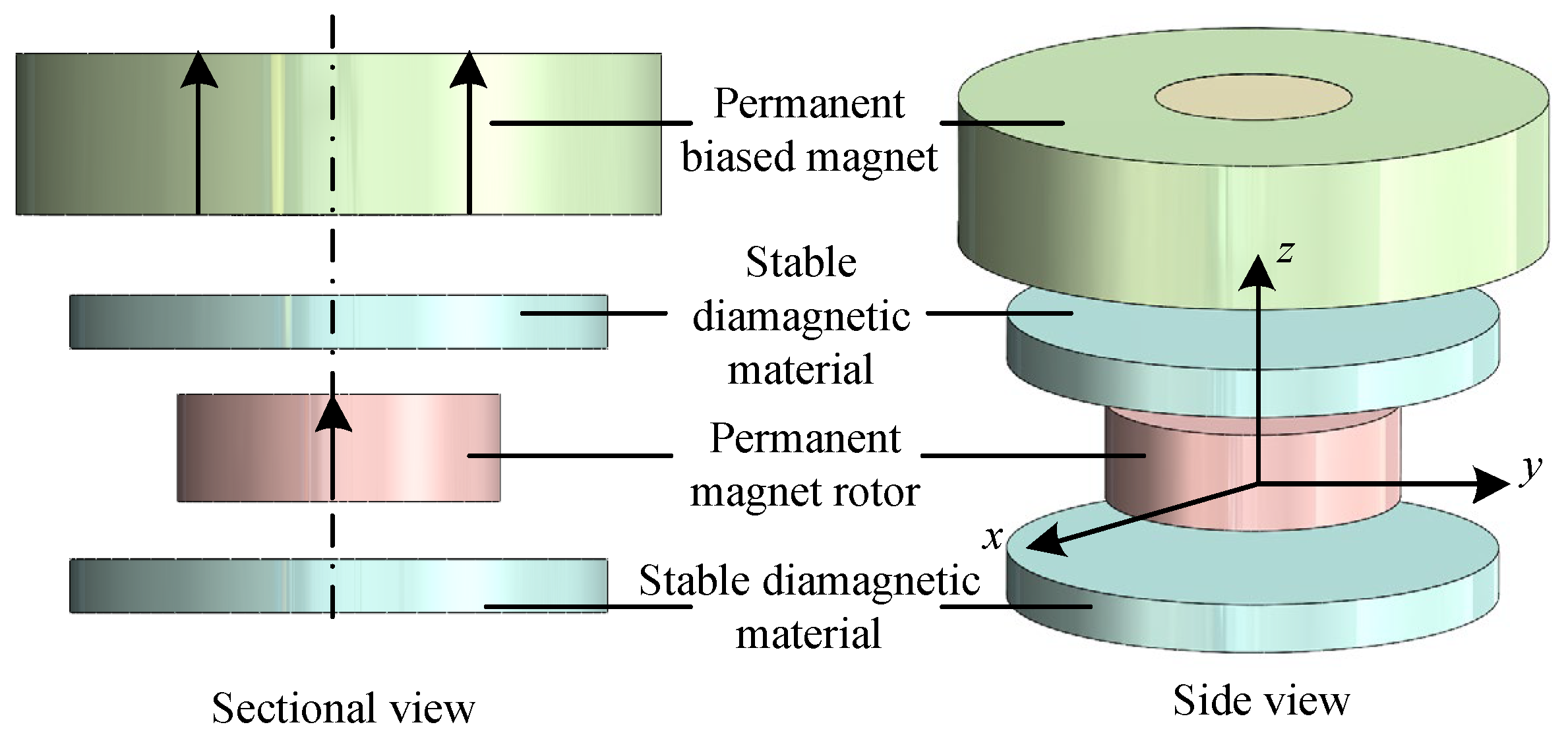
2.2.2. Diamagnetic Magnetic Bearings
2.3. Statistical Comparison Between the Magnetic Bearings
2.4. Chapter Summary
3. Modeling of Magnetic Suspension Bearing
3.1. Modeling of Suction Magnetic Bearings
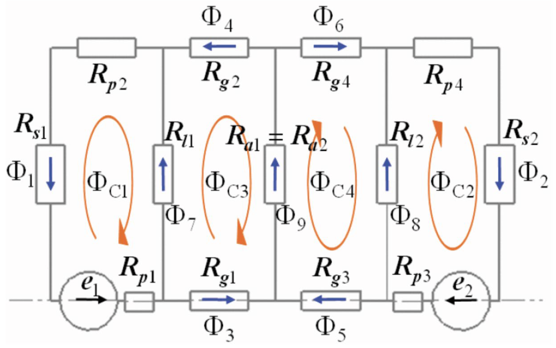
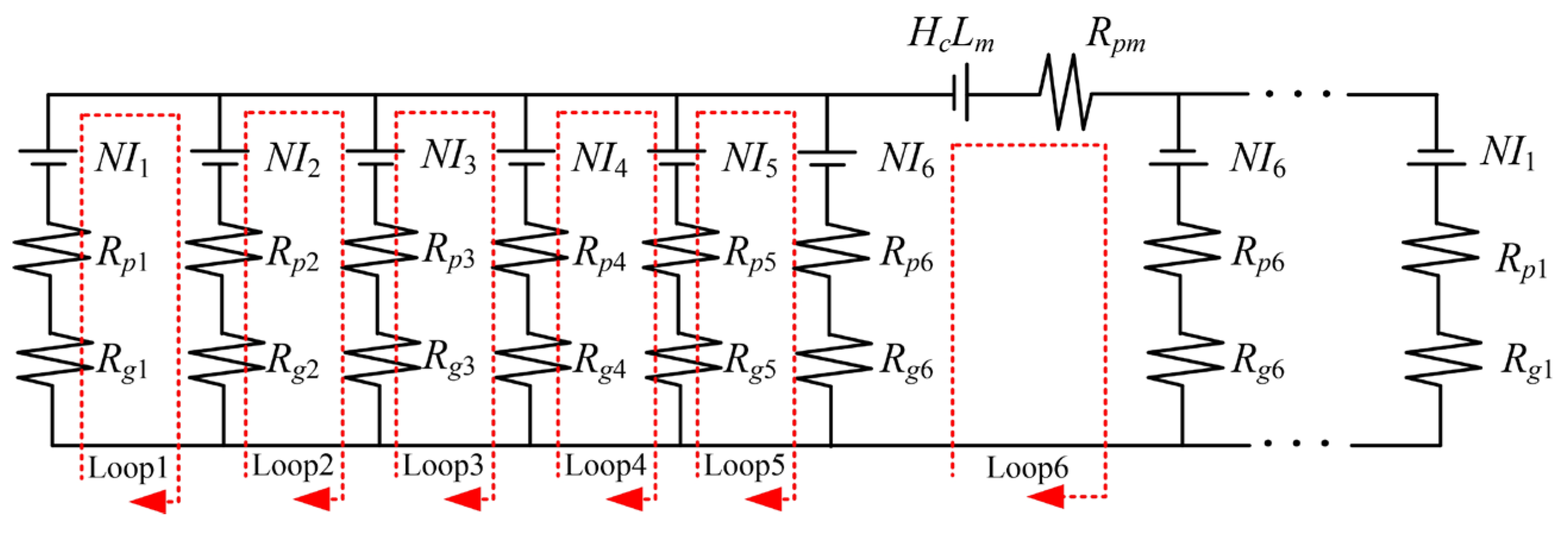
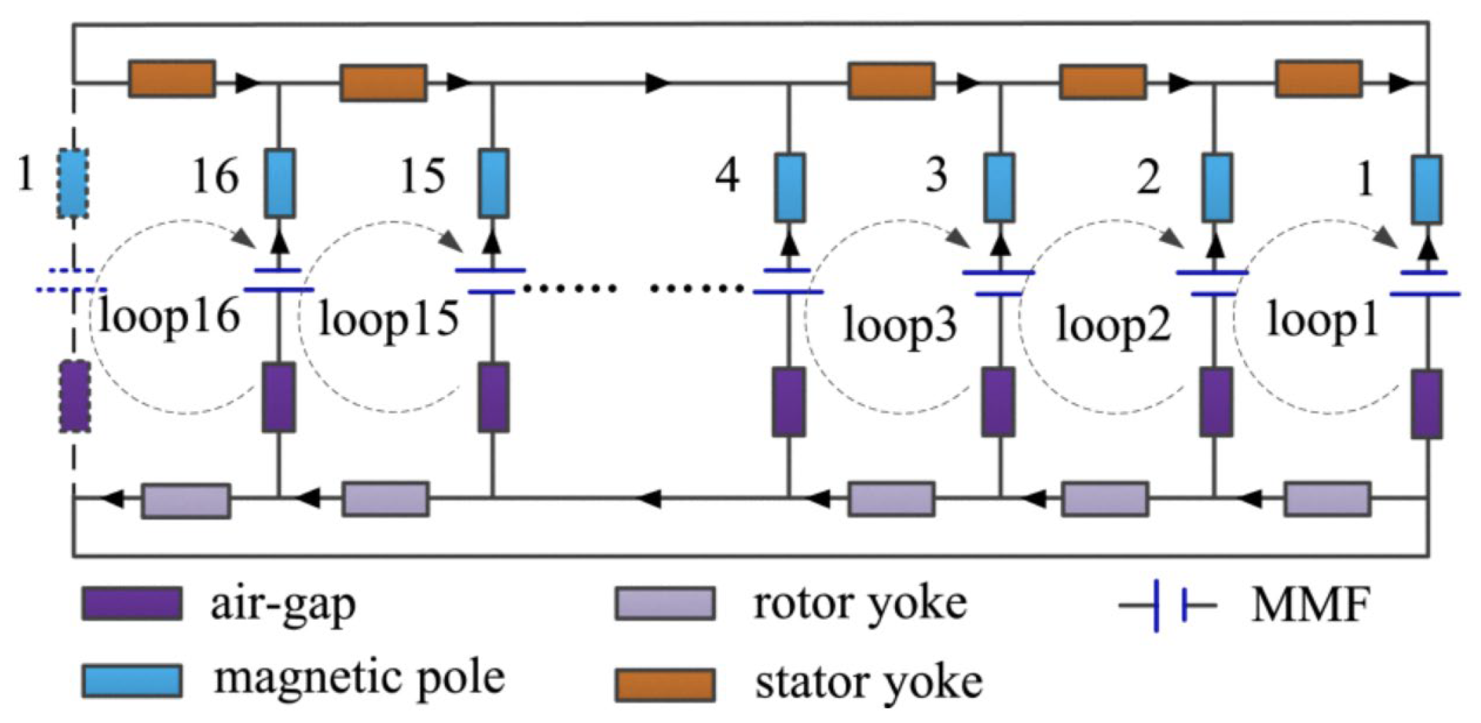
3.1.1. Modeling of Electromagnetic (Active) Magnetic Bearings
3.1.2. Modeling of Hybrid Magnetic Bearings
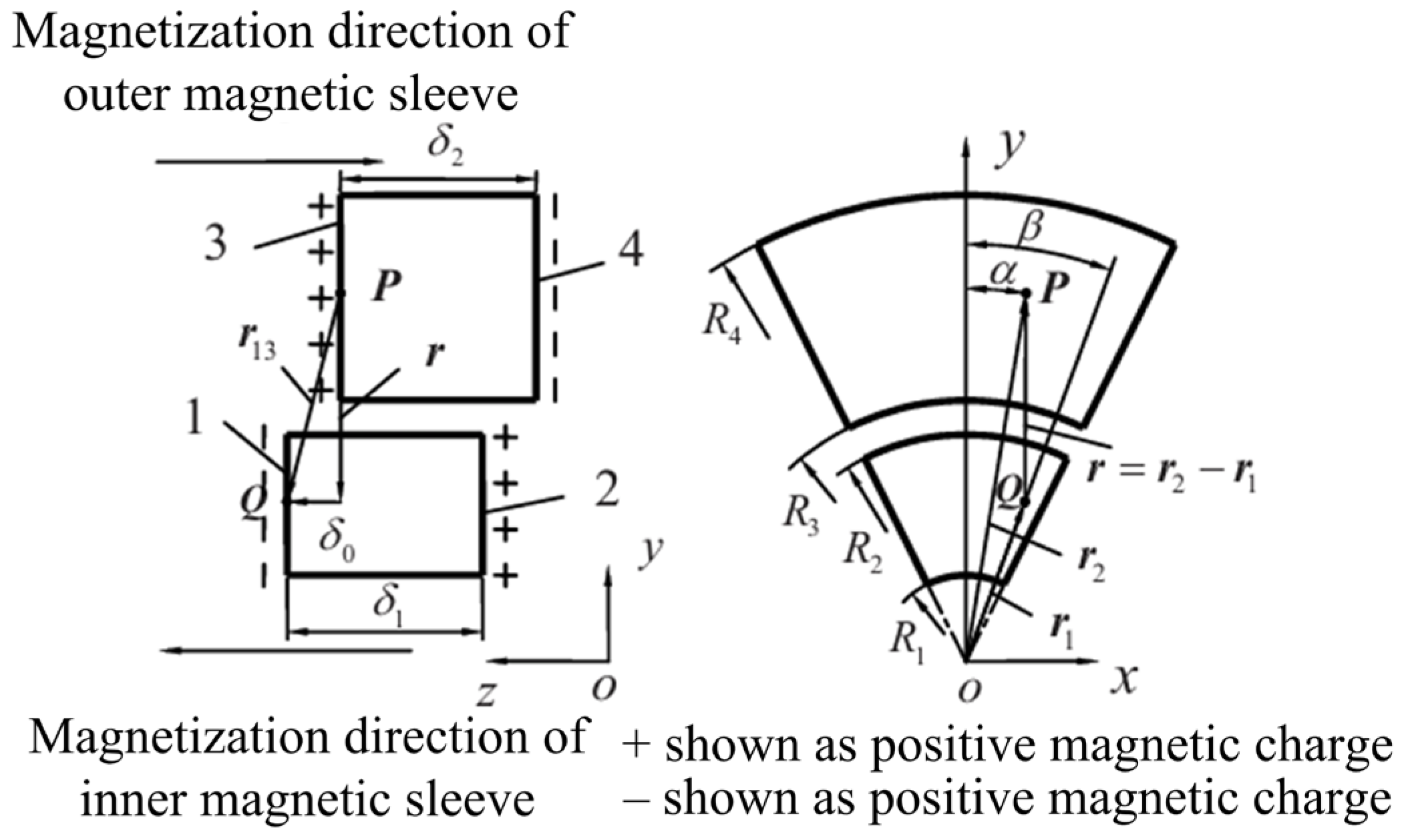
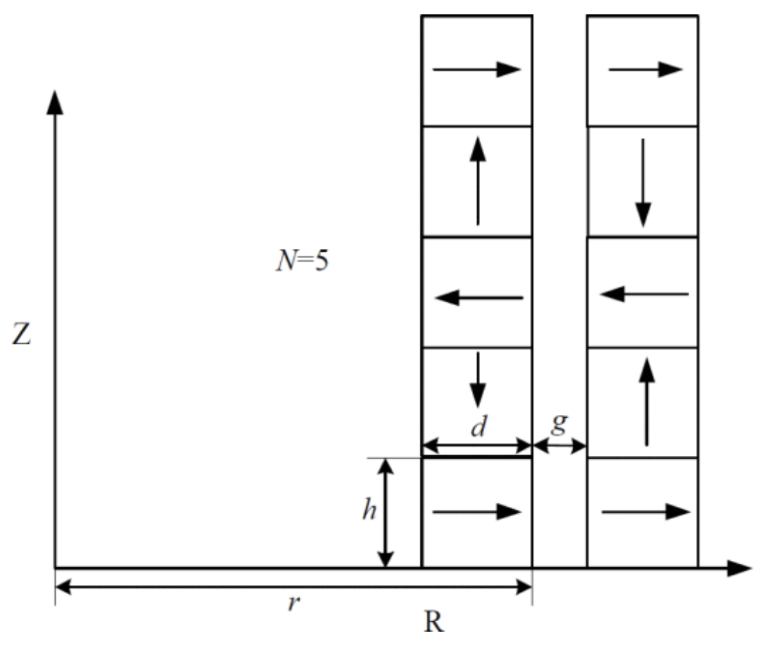
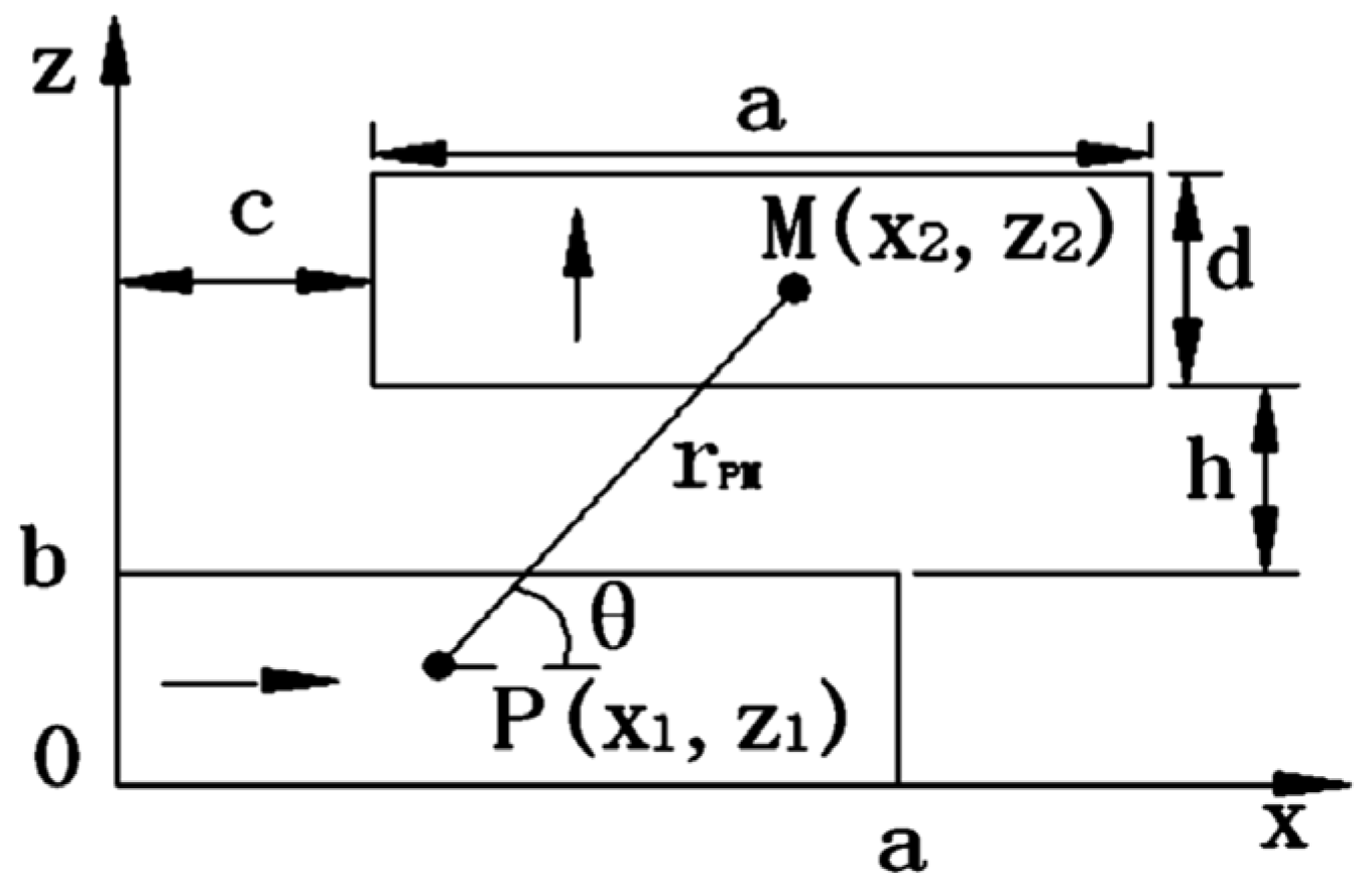
3.1.3. Modeling of Passive Magnetic Bearings
- (1)
- Assume that the remanent magnetization of the permanent-magnet material is high;
- (2)
- Ignore the influence of curvature on calculation accuracy;
- (3)
- Assume that the two parallel magnets are infinitely long.
3.2. Modeling of Repulsive Magnetic Bearings
3.2.1. Modeling of Passive Magnetic Bearings
3.2.2. Modeling of Diamagnetic Bearings
3.3. Chapter Summary
4. Magnetic Bearing Control Strategies
4.1. Suction Type Magnetic Bearing Control Strategies
4.1.1. Low Power Control Strategies
4.1.2. Zero Displacement Control Strategies
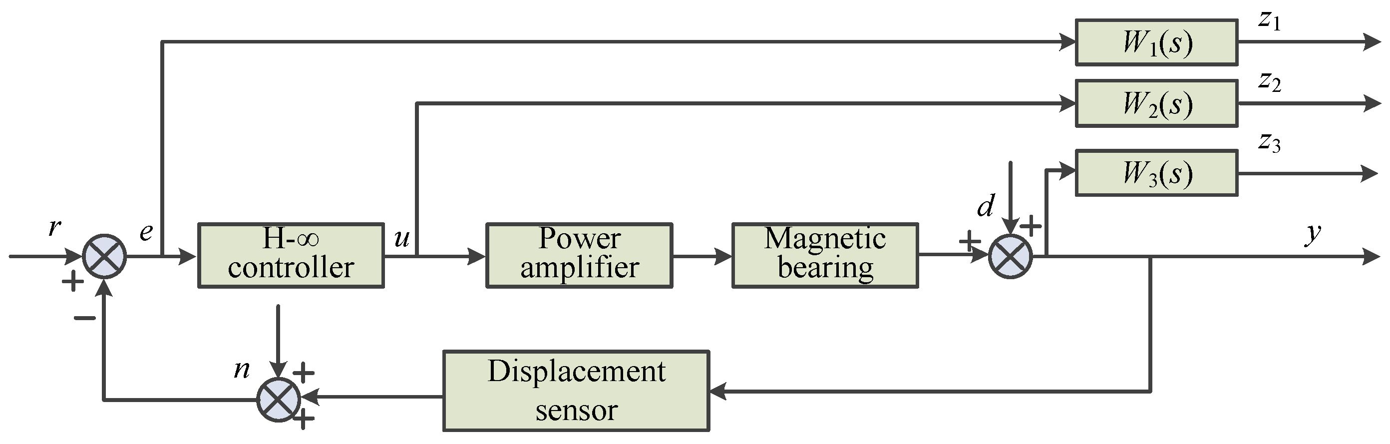
4.1.3. Robust Control Strategies
4.1.4. No Sensing Detection Control Strategies
4.2. Repulsive Magnetic Bearing Control Strategies
4.3. Chapter Summary
5. Conclusions and Future Perspectives
Author Contributions
Funding
Data Availability Statement
Conflicts of Interest
References
- Earnshaw, S. On the Nature of the Molecular Forces which Regulate the Constitution of the Lumiferous Ether. Trans. Camb. Philharm. Soc. 1842, 3, 97–112. [Google Scholar]
- Kemper, H. Schwebebahn Mit Raederlosen Fahrzeugen, Die an Eisernen Fahrschienen Mittels Magnetischer Felder Schwebend Entlang Gefuehrt Werden. Germany Patent No. 6443316, 5 April 1937. [Google Scholar]
- Kemper, H. Suspension by Electromagnetic Forces: A Possibility for A Radically New Method of Transportation. Elektrotechnische Z. 1938, 59, 391–395. [Google Scholar]
- Beams, J.W. Magnetic Suspension for Small Rotors. Rev. Sci. Instrum. 1950, 21, 182–184. [Google Scholar] [CrossRef]
- Schweitzer, G. Ein Aktives Magnetisches Rotorlager-Auslegung und Anwendung. Regelungstechnik 1978, 26, 10–15. [Google Scholar]
- Chu, Y.L.; Wang, X.P.; Lei, Y.F.; Xia, C.Y.; Tang, H.; Wang, L.; Qian, J. Intelligent Method of Information Storage and Interface in Magnetic Bearing System. Bearing 2007, 9, 14. [Google Scholar]
- Knospe, C.R. Introductin to the Special Issue on Magnetic Bearing. IEEE Trans. Control Syst. Technol. 1996, 4, 481–485. [Google Scholar] [CrossRef]
- Brunet, M. Practical Applications of Active Magnetic Bearing to the Industrial World. In Proceedings of the 1st International Symposium on Magnetic Bearings, Zurich, Switzerland, 6–8 June 1988. [Google Scholar]
- Taniguchi, M. Cutting Performance of Digital Controlled Milling AMB-spindle. In Proceedings of the 5th International Symposium on Magnetic Bearings, Kanazawa, Japan, 28–30 August 1996. [Google Scholar]
- Sun, J.J.; Fang, J.C. Design on New Permanent Magnet Biased Radial Magnetic Bearing in Magnetic Suspending Flywheel. Bearing 2008, 3, 8–13. [Google Scholar]
- Hofmann, W. Behaviour and Control of An Inverter-fed Three-pole Active Radial Magnetic Bearing. In Proceedings of the IEEE International Symposium on Industrial Electronics, Rio de Janeiro, Brazil, 9–11 June 2003; pp. 974–979. [Google Scholar]
- Schmidt, E.; Hofer, M. Parameter Evaluation of A Hybrid Magnetic Bearing by Using 3D Finite Element Analyses. In Proceedings of the Australasian Universities Power Engineering Conference, Sydney, Australia, 14–17 December 2008; pp. 1–6. [Google Scholar]
- Kim, S.H.; Shin, J.W.; Ishiyama, K. Magnetic bearings and synchronous magnetic axial coupling for the enhancement of the driving performance of magnetic wireless pumps. IEEE Trans. Magn. 2014, 50, 400–403. [Google Scholar] [CrossRef]
- Gong, L.; Zhu, C.S. The Influence of PID Controller Parameters on Polarity Switching Control for Unbalance Compensation of Active Magnetic Bearings Rotor Systems. IEEE Trans. Ind. Electron. 2024, 71, 8324–8338. [Google Scholar]
- Dutta, D.; Kumar Biswas, P.; Debnath, S.; Ahmad, F. Advancements and Challenges in Active Magnetic Bearings: A Comprehensive Review of Performance, Control, and Future Prospects. IEEE Access 2025, 13, 3051–3071. [Google Scholar] [CrossRef]
- Lee, R.M.; Wu, Z.B.; Wang, C.C.; Chen, T.C. Multi-hybrid Active Magnetic Bearing Design for Milling Spindle Applications. Sens. Mater. 2020, 32, 375–385. [Google Scholar] [CrossRef]
- Santra, T.; Roy, D.; Choudhury, A.B.; Yamada, S. Multiphysics Modelling of A Hybrid Magnetic Bearing (HMB) for Calculating Power Loss and Temperature with Different Loss Minimization Strategies. Tribol. Finn. J. Tribol. 2019, 36, 24–35. [Google Scholar] [CrossRef]
- Wan, S.K.; Xi, H.H.; Li, X.H.; Hong, J.; Jiang, Z. Active Spindle System Hybrid-supported with Active Magnetic Bearing. Bearing 2022, 12, 17–22. [Google Scholar]
- Jiang, K.J.; Zhu, C.S.; Chen, L.L. Unbalance Compensation by Recursive Seeking Unbalance Mass Position in Active Magnetic Bearing-Rotor System. IEEE Trans. Ind. Electron. 2015, 62, 5655–5664. [Google Scholar]
- Schweitzer, G.; Maslen, E.H. Magnetic Bearings: Theory, Design, and Application to Rotating Machinery; Springer: Dordrecht, The Netherlands, 2009. [Google Scholar]
- Zhang, W.Y.; Zhu, H.Q. Radial Magnetic Bearings: An Overview. Results Phys. 2017, 7, 3756–3766. [Google Scholar] [CrossRef]
- García, P.; Guerrero, J.M.; Briz, F.; Reigosa, D.D. Sensorless Control of Three-pole Active Magnetic Bearings Using Saliency-tracking-based Methods. IEEE Trans. Ind. Appl. 2010, 46, 1476–1484. [Google Scholar] [CrossRef]
- Xu, S.L.; Fang, J.C. A Novel Conical Active Magnetic Bearing with Claw Structure. IEEE Trans. Magn. 2014, 50, 1–8. [Google Scholar]
- Zhang, W.Y.; Yang, H.K.; Cheng, L.; Zhu, H. Modeling Based on Exact Segmentation of Magnetic Field for a Centripetal Force Type-magnetic Bearing. IEEE Trans. Ind. Electron. 2020, 67, 7691–7701. [Google Scholar] [CrossRef]
- Zhang, W.Y.; Wang, J.P.; Zhu, P.F.; Yu, J.X. A Novel Vehicle-Mounted Magnetic Suspension Flywheel Battery with a Virtual Inertia Spindle. IEEE Trans. Ind. Electron. 2022, 69, 5973–5983. [Google Scholar] [CrossRef]
- Xu, S.L.; Sun, J.J.; Ren, H.L. An Active Magnetic Bearing with Controllable Permanent-Magnet Bias Field. IEEE/ASME Trans. Mech. 2022, 27, 3474–3481. [Google Scholar] [CrossRef]
- Zhang, W.Y.; Zhu, H.Q. Control System Design for A Five-Degree-Of-Freedom Electrospindle Supported with AC Hybrid Magnetic Bearings. IEEE/ASME Trans. Mech. 2015, 20, 2525–2537. [Google Scholar] [CrossRef]
- Masuzawa, T.; Kojima, J.; Onuma, H.; Okada, Y.; Nishida, M.; Yamane, T. Micro Magnetic Bearing for An Axial Flow Artificial Heart. In Proceedings of the 9th International Symposium on Magnetic Bearings, Lexington, KY, USA, 3–6 August 2004; University of Kentucky: Lexington, KY, USA, 2004; pp. 89–94. [Google Scholar]
- Blumenstock, K.; Brown, G. Novel Integrated Radial and Axial Magnetic Bearing. In Proceedings of the 7th International Symposium on Magnetic Bearings, Zurich, Switzerland, 23–25 August 2000; ETH Zurich: Zurich, Switzerland, 2000; pp. 467–471. [Google Scholar]
- Zhang, W.Y.; Wang, J.W.; Li, A.; Xiang, Q. Multiphysics Fields Analysis and Optimization Design of a Novel Saucer-Shaped Magnetic Suspension Flywheel Battery. IEEE Trans. Transp. Electrif. 2024, 10, 5473–5483. [Google Scholar] [CrossRef]
- Hu, J.C.; Wu, H.C.; Fang, K.P.; Li, Q. Overview on Structure of Permanent Magnetic Bearings. Bearing 2023, 7, 1–7. [Google Scholar]
- Maxence, B.V.; Virginie, K.; Bruno, D. Optimal Sizing and Comparison of Permanent Magnet Thrust Bearings. IEEE Trans. Magn. 2017, 53, 1–10. [Google Scholar]
- Toh, C.S.; Chen, S.L. Design and Control of a Ring-type Flywheel Battery System with Hybrid Halbach Magnetic Bearings. In Proceedings of the 2014 IEEE/ASME International Conference on Advanced Intelligent Mechatronics, Besacon, France, 8–11 July 2014; pp. 1558–1562. [Google Scholar]
- Yoo, S.-Y.; Kim, W.-Y.; Kim, S.-J.; Lee, W.-R.; Bae, Y.-C.; Noh, M. Optimal Design of Non-Contact Thrust Bearing Using Permanent Magnet Rings. Int. J. Precis. Eng. Manuf. 2011, 12, 1009–1014. [Google Scholar] [CrossRef]
- Azukizawa, T.; Yamamoto, S.; Matsuo, N. Feasibility Study of a Passive Magnetic Bearing Using the Ring Shaped Permanent Magnets. IEEE Trans. Magn. 2008, 44, 4277–4280. [Google Scholar] [CrossRef]
- Han, B.C.; Zheng, S.Q.; Le, Y.; Xu, S. Modeling and Analysis of Coupling Performance Between Passive Magnetic Bearing and Hybrid Magnetic Radial Bearing for Magnetically Suspended Flywheel. IEEE Trans. Magn. 2013, 49, 5356–5370. [Google Scholar] [CrossRef]
- Janssen, J.L.G.; Paulides, J.J.H.; Lomonova, E. Passive Magnetic Suspension Limitations for Gravity Compensation. In Proceedings of the 11th International Symposium on Magnetic Bearings, Mito, Japan, 26–28 August 2002; pp. 83–90. [Google Scholar]
- Braunbek, W. Frei Schwebende Körper im Elektrischen und Magnetischen Feld. Z. Phys. 1939, 112, 753. [Google Scholar] [CrossRef]
- Arkadiev, V. A Floating Magnet. Nature 1947, 160, 330. [Google Scholar] [CrossRef]
- Li, W.X.; Yang, T.H.; Xin, Y. Principle, Modeling and Experiment of a New Axial-Type Superconducting Magnetic Bearing with Superconducting Coil. IEEE Trans. Appl. Supercon. 2024, 34, 1–5. [Google Scholar] [CrossRef]
- Xu, Y.P.; Cui, Q.W.; Kan, R.; Bleuler, H.; Zhou, J. Realization of a Diamagnetically Levitating Rotor Driven by Electrostatic Field. IEEE/ASME Trans. Mech. 2017, 22, 2387–2391. [Google Scholar] [CrossRef]
- Cansiz, A.; Hull, J.R. Stable Load-carrying and Rotational Loss Characteristics of Diamagnetic Bearings. IEEE Trans. Magn. 2004, 40, 1636–1641. [Google Scholar] [CrossRef]
- Lee, E. A Micro HTS Renewable Energy/Attitude Control System for Micro/Nano Satellites. IEEE Trans. Appi. Supercon. 2003, 13, 2263–2266. [Google Scholar]
- Cansiz, A. Static and Dynamic Analysis of a Diamagnetic Bearing System. J. Appl. Phys. 2008, 103, 034510. [Google Scholar] [CrossRef]
- Su, Y.F.; Xiao, Z.M.; Ye, Z.T.; Takahata, K. Micromachined Graphite Rotor Based on Diamagnetic Levitation. IEEE Electron Device Lett. 2015, 36, 393–395. [Google Scholar] [CrossRef]
- Martynenko, G. Accounting for an Interconnection of Electrical, Magnetic and Mechanical Processes in Modeling the Dynamics of Turbomachines Rotors in Passive and Controlled Active Magnetic Bearings. In Proceedings of the 2018 IEEE 3rd International Conference on Intelligent Energy and Power Systems (IEPS), Kharkiv, Ukraine, 10–14 September 2018; pp. 326–331. [Google Scholar]
- Shakibapour, F.; Rahideh, A.; Mardaneh, M. 2D Analytical Model for Heteropolar Active Magnetic Bearings Considering Eccentricity. IET Electr. Power Appl. 2018, 12, 614–626. [Google Scholar] [CrossRef]
- Du, T.; Geng, H.; Zhang, Y.; Lin, H.; Li, Y.; Yu, L. Exact Analytical Method for Active Magnetic Bearings with Rotor Eccentricity. IEEE Trans. Magn. 2019, 55, 1–12. [Google Scholar] [CrossRef]
- Wang, K.; Wang, D.; Shen, Y.; Zhang, X.; Chen, J.; Zhang, Y. Subdomain Method for Permanent Magnet Biased Homopolar Radial Magnetic Bearing. IEEE Trans. Magn. 2016, 52, 1–5. [Google Scholar]
- Kang, K.; Palazzolo, A. Homopolar Magnetic Bearing Saturation Effect on Rotating Machinery Vibration. IEEE Trans. Magn. 2012, 48, 1984–1994. [Google Scholar] [CrossRef]
- Jiang, H.; Su, Z.Z.; Wang, D. Analytical Calculation of Active Magnetic Bearing Based on Distributed Magnetic Circuit Method. IEEE Trans. Energy Conver. 2021, 36, 1841–1851. [Google Scholar] [CrossRef]
- Wu, M.Y.; Zhu, H.Q.; Zhang, H.; Zhang, W.Y. Modeling and Multilevel Design Optimization of an AC–DC Three-Degree-of-Freedom Hybrid Magnetic Bearing. IEEE Trans. Ind. Electron. 2023, 70, 233–242. [Google Scholar] [CrossRef]
- Wang, K.; Wang, D.; Lin, H.; Shen, Y.; Zhang, X.; Yang, H. Analytical Modeling of Permanent Magnet Biased Axial Magnetic Bearing with Multiple Air Gaps. IEEE Trans. Magn. 2014, 50, 1–4. [Google Scholar] [CrossRef]
- Zhang, W.Y.; Zhu, H.Q. Precision Modeling Method Specifically for AC Magnetic Bearings. IEEE Trans. Magn. 2013, 49, 5543–5553. [Google Scholar] [CrossRef]
- Yonnet, J.P. Analytical Calculation of Magnetic Bearings. In Proceedings of the 5th International Workshop on Rare Earth-Cobalt Permanent Magnets and Their Applications, Roanoke, VA, USA, 7–10 June 1981; Volume 3, pp. 199–216. [Google Scholar]
- Dellinger, S.J.; Smith, A.O.; Stmat, K.J. Field and force calculations for use in Passive Magnetic Bearing Systems Employing Rare Earth Magnets. In Proceedings of the 8th International Workshop on Rare Earth-Cobalt Permanent Magnets and Their Applications, Dayton, OH, USA, 6–8 May 1985; Volume 6, pp. 153–164. [Google Scholar]
- Wang, C.Y.; Tan, Q.C. Analysis of Magnetic Field Distribution in Disc Magnetic Drivers. Energy Procedia 2012, 17, 183–188. [Google Scholar] [CrossRef]
- Li, J.G.; Tan, Q.C.; Zhang, Y.Q.; Zhang, K. Study on the Calculation of Magnetic Force Based on the Equivalent Magnetic Charge Method. Phys. Procedia 2012, 24, 190–197. [Google Scholar] [CrossRef]
- Wang, N.X.; Wang, D.X.; Chen, K.S.; Wu, H.C. Research on Analytical Model and Design Formulas of Permanent Magnetic Bearings Based on Halbach Array with Arbitrary Segmented Magnetized Angle. J. Magn. Magn. Mater. 2016, 410, 257–264. [Google Scholar] [CrossRef]
- Chen, Y.; Zhang, W.L.; Bird, J.Z.; Paul, S.; Zhang, K.L. A 3-D Analytic-Based Model of a Null-Flux Halbach Array Electrodynamic Suspension Device. IEEE Trans. Magn. 2015, 51, 1–5. [Google Scholar] [CrossRef]
- Xu, F.P.; Li, T.C.; Liu, Y.J. A study on Passive Magnetic Bearing with Halbach Magnetized Array. In Proceedings of the 2008 International Conference on Electrical Machines and Systems, Wuhan, China, 17–20 October 2008; pp. 417–420. [Google Scholar]
- Tian, L.L.; Ai, X.P.; Tian, Y.Q. Analytical Model of Magnetic Force for Axial Stack Permanent Magnet Bearings. IEEE Trans. Magn. 2012, 48, 2592–2699. [Google Scholar] [CrossRef]
- Chang, P.Z.; Moon, F.C.; Hull, J.R. Levitation Force and Magnetic Stiffness in Bulk High-Temperature Superconductors. J. Appl. Phys. 1990, 67, 4358–4360. [Google Scholar] [CrossRef]
- Han, Y.H.; Park, B.J.; Jung, S.Y.; Han, S.C.; Lee, W.R.; Bae, Y.C. The Improved Damping of Superconductor Bearings for 35 kWh Superconductor Flywheel Energy Storage System. Phys. C Supercond. Its Appl. 2013, 485, 102–106. [Google Scholar] [CrossRef]
- Simon, I.; Emslie, A.G.; Strong, P.E.; McConnell, R.K. Sensitive Tiltmeter Utilizing a Diamagnetic Suspension. Rev. Sci. Instrum. 1968, 39, 1666–1671. [Google Scholar] [CrossRef]
- Schroder, P.; Green, B.; Grum, N.; Fleming, P.J. On-line Evolution of robust control systems: An Industrial Active Magnetic Bearing Application. Control Eng. Pract. 2001, 9, 37–49. [Google Scholar] [CrossRef]
- Tsiotras, P.; Arcak, M. Low-bias Control of AMB Subject to Voltage Saturation: State-feedback and Observer Designs. IEEE Trans. Control. Syst. Technol. 2005, 13, 262–273. [Google Scholar] [CrossRef]
- Mizuno, T.; Takasaki, M.; Hara, M.; Yamaguchi, D.; Ishino, Y. Zero-power Control of Flux-Path Control Magnetic Suspension System with Flux-Interrupting Plates. In Proceedings of the 2017 11th International Symposium on Linear Drives for Industry Applications (LDIA), Osaka, Japan, 6–8 September 2017; pp. 1–6. [Google Scholar]
- Hoque, M.E.; Mizuno, T.; Ishino, Y.; Takasaki, M. A six-axis hybrid vibration isolation system using active zero-power Control Supported by Passive Weight Support Mechanism. J. Sound Vib. 2010, 329, 3417–3430. [Google Scholar] [CrossRef]
- Lum, K.Y.; Coppola, V.T.; Bernstein, D.S. Adaptive Autocentering Control for An Active Magnetic Bearing Supporting a Rotor with Unknown Mass Imbalance. IEEE Trans. Control. Syst. Technol. 1996, 4, 587–597. [Google Scholar] [CrossRef]
- Kim, C.S.; Lee, C.W. In Situ Runout Identification in Active Magnetic Bearing System by Extended Influence Coefficient Method. IEEE/ASME Trans. Mech. 1996, 2, 51–57. [Google Scholar]
- Ranjan, G.; Tiwari, R. Application of Active Magnetic Bearings for in Situ Flexible Rotor Residual Balancing Using a Novel Generalized Influence Coefficient Method. Inverse Probl. Sci. Eng. 2018, 27, 943–968. [Google Scholar] [CrossRef]
- Jian, Z.; Huachun, W.; Weiyu, W.; Kezhen, Y.; Yefa, H.; Xinhua, G.; Chunsheng, S. Online Unbalance Compensation of a Maglev Rotor with Two Active Magnetic Bearings Based on The LMS Algorithm and The Influence Coefficient Method. Mech. Syst. Signal Process. 2022, 166, 108460. [Google Scholar] [CrossRef]
- Mao, C.; Zhu, C.S. Unbalance compensation for Active Magnetic Bearing Rotor System Using a Variable Step Size Real-time Iterative Seeking Algorithm. IEEE Trans. Ind. Electron. 2018, 65, 4177–4186. [Google Scholar]
- Schuhmann, T.; Hofmann, W.; Werner, R. Improving operational performance of Active Magnetic Bearings Using Kalman Filter and State Feedback Control. IEEE Trans. Ind. Electron. 2011, 59, 821–829. [Google Scholar] [CrossRef]
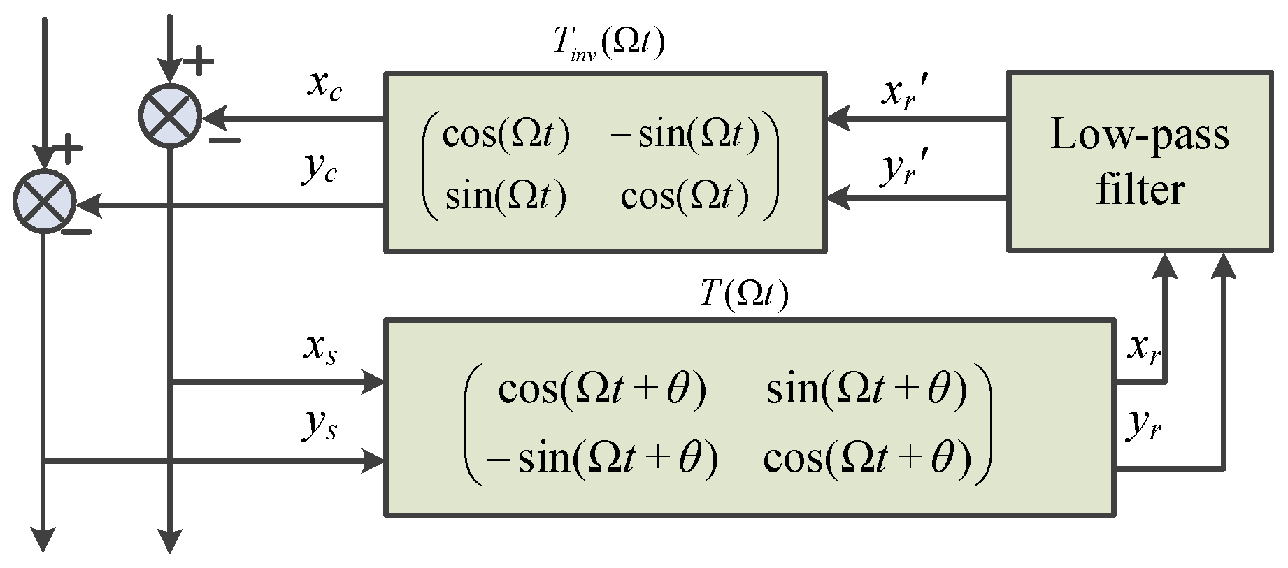
- Zheng, S.Q.; Han, B.C.; Feng, R.; Jiang, Y. Vibration suppression control for AMB Supported Motor Driveline System Using synchronous Rotating Frame Transformation. IEEE Trans. Ind. Electron. 2015, 62, 5700–5708. [Google Scholar] [CrossRef]
- Cui, P.L.; Liu, Z.Y.; Xu, H.; Zheng, S.Q.; Han, B.C.; Zhang, D.C. Harmonic Vibration Force Suppression of Magnetically Suspended Rotor with Frequency-Domain Adaptive LMS. IEEE Sens. J. 2020, 20, 1166–1175. [Google Scholar] [CrossRef]
- Ju, J.T.; Zhu, H.Q.; Zhao, C.Y. Radial Force-Current Characteristic Analysis of Three-Pole Radial-Axial HMB. In Proceedings of the 2016 IEEE Vehicle Power and Propulsion Conference (VPPC), Hangzhou, China, 17–20 October 2016; pp. 1–6. [Google Scholar]
- Fu, X.D.; Cao, G.Z.; Huang, S.D.; Wu, C. Fuzzy PID control of the planar switched reluctance motor for precision positioning. In Proceedings of the 2017 7th International Conference on Power Electronics Systems and Applications-Smart Mobility, Power Transfer & Security (PESA), Hong Kong, China, 12–14 December 2017; pp. 1–4. [Google Scholar]
- Li, J.; Xia, Y.Q.; Qi, X.H.; Gao, Z.Q. On the Necessity, Scheme, and Basis of the Linear–Nonlinear Switching in Active Disturbance Rejection Control. IEEE Trans. Ind. Electron. 2017, 64, 1425–1435. [Google Scholar] [CrossRef]
- Su, Z.Z.; Wang, D.; Wu, L.T.; Wang, K. Identification and Mixed-sensitivity H∞ Control of Permanent Magnet Biased Axial Magnetic Bearing with Multiple Air Gaps. In Proceedings of the 2015 IEEE International Conference on Applied Superconductivity and Electromagnetic Devices (ASEMD), Shanghai, China, 20–23 November 2015; pp. 248–250. [Google Scholar]
- Chen, Y.Q.; Song, P.Y.; Zhang, J.Y.; Zhang, K.Y. Robust controller design for active suspension based on μ-synthesis. In Proceedings of the 2011 International Conference on Electronic & Mechanical Engineering and Information Technology, Harbin, China, 12–14 August 2011; pp. 3229–3233. [Google Scholar]
- Kuseyri, I.S. Robust Control and Unbalance Compensation of Rotor/Active Magnetic Bearing Systems. J. Vib. Control 2012, 18, 817–832. [Google Scholar] [CrossRef]
- Nonami, K.; Ito, T. μ Synthesis of Flexible Rotor-magnetic Bearing Systems. IEEE Trans. Control. Syst. Technol. 1996, 4, 503–512. [Google Scholar] [CrossRef]
- Sun, J.B.; Zhu, H.Q. Self-Sensing Technology of Rotor Displacement for Six-Pole Radial Active Magnetic Bearing Using Improved Quantum Particle Swarm Optimized Cubature Kalman Filter. IEEE J. Emerg. Sel. Top. Power Electron. 2022, 10, 2881–2889. [Google Scholar] [CrossRef]
- Sun, J.J.; Chen, D.; Ren, H.L. Modeling and Control of an Integrated Axial Passive and Radial Active Magnetic Bearing System. In Proceedings of the 2013 IEEE International Conference on Information and Automation (ICIA), Yinchuan, China, 26–28 August 2013; pp. 682–687. [Google Scholar]
- Chakraborty, A.; Santra, T.; Roy, D.; Yamada, S. Modelling and Stability Analysis of a Repulsive Type Magnetic Bearing. In Proceedings of the 2015 International Conference on Energy, Power and Environment: Towards Sustainable Growth (ICEPE), Shillong, India, 12–13 June 2015; pp. 1–6. [Google Scholar]
- Fang, J.C.; Ren, Y. High-Precision Control for a Single-Gimbal Magnetically Suspended Control Moment Gyro Based on Inverse System Method. IEEE Trans. Ind. Electron. 2011, 58, 4331–4342. [Google Scholar] [CrossRef]
- Peng, C.; He, J.; Deng, Z.; Liu, Q. Parallel Mode Notch Filters for Vibration Control of Magnetically Suspended Flywheel in the Full Speed Range. IET Electr. Power Appl. 2020, 14, 1672–1678. [Google Scholar] [CrossRef]


| Applications | Power (kW) | Speed (rpm) |
|---|---|---|
| Power Generation | 2–150 | 35,000–220,000 |
| Flywheel Energy Storage System | 120 | 40,000 |
| High-Speed Spindles | 1–24 | 9000–180,000 |
| Turbo Molecular Pumps | Few hundred Watt | 100,000 |
| Gas Compressors | 10,000 | 20,000 |
| Air Compressors | 100–150 | 80–15,000 |
| Micro Turbines | 50 | 80,000 |
| Turbo Generators | 30 | 60,000 |
| Type of Magnetic Suspension Bearing | Statical Performance | The Suspension Magnetic Force | Application | Limitations | |
|---|---|---|---|---|---|
| Suction magnetic bearing | AMB | The electromagnet provides the base suspension force and is adjustable in real time. The stiffness and damping can be flexibly adjusted by the control algorithm. The bearing capacity and stiffness are large. | In [23], when the offset of the rotor in the z direction is 30 mm, the suspension magnetic force is 21 N, the displacement stiffness is 0.7 N/μm. The maximum rate of change of z-axis force is 0.29%. | Aero engines, satellite attitude control, high speed motors, turbomolecular pumps, etc. | High hardware and maintenance costs, high system complexity, and vulnerability to electromagnetic interference. |
| HMB | The permanent magnet provides the basic suspension force, and the electromagnet regulates the suspension force. High overall stiffness, stiffness adjustability. The combination of passive damping and active damping can optimize the damping performance. | In [25], when the offset of the rotor in the x direction is 0.2 mm, the suspension magnetic force is 16 N. | High speed motor, aero engine, satellite attitude control, flywheel energy storage., etc. | Complex magnetic field design, high-precision manufacturing requirements, high material, maintenance costs, and complex control systems. | |
| PMB | Permanent magnet provides suction force, has self-balancing ability in a certain range, nonlinear stiffness, stiffness is closely related to the air gap, the inherent damping is small, dependent on structural damping. | In [32], when the offset of the rotor in the z direction is 2 mm, the suspension magnetic force is 10 KN, the displacement stiffness is 2 N/m. | Small rotary equipment, precision balance, gyroscope, vacuum environment equipment, high-temperature environment equipment, etc. | Limited suspension force and carrying capacity, limited by permanent magnet performance and air gap, stability affected by nonlinear characteristics, lack of active adjustment ability, sensitive to the environment. | |
| Repulsive magnetic bearing | PMB | The repulsion force of permanent magnet produces suspension, the suspension force is strongly related to the distance, the nonlinear stiffness, the stiffness adjustment is difficult, the inherent damping is small, and the damping can be increased by structural design. | In [23], when the offset of the rotor in the z direction is 30 mm, the suspension magnetic force is 21 N, the displacement stiffness is 0.7 N/μm. | Small motor, micro pump, precision balance, optical gyroscope, vacuum environment equipment, radioactive environment, etc. | The limitations are similar to those of suction passive magnetic bearings. Suspension force and load capacity are limited by permanent magnet performance and air gap, stability is affected by nonlinear characteristics, lack of active adjustment ability, and sensitive to temperature and magnetic field. |
| DMB | The diamagnetic effect produces the suspension force, which is relatively small and stable, and the stiffness is low. The stiffness is related to the material and magnetic field distribution, and the inherent damping is small, which can be increased by additional structures. | In [41], when the offset of the rotor in the z direction is 3 mm, the suspension magnetic force is 13 KN. | Optical chopper, gyroscope, biochip, crystal holographic interferometer, high precision force sensor, etc. | The suspension force and carrying capacity are limited, the stiffness and stability are insufficient, and the application range is limited. | |
| Type of Magnetic Suspension Bearing | Action Principle | Characteristics | |
|---|---|---|---|
| Suction magnetic bearing | AMB | The rotor is supported by the suspension force generated by the electromagnet, and the position of the rotor is precisely located by the displacement sensor. The control system adjusts the magnetic force by adjusting the current intensity to correct and maintain the stable operation of the rotor on the predetermined trajectory. The device is mainly composed of an electromagnet, a displacement sensor, a rotor, a power amplifier and a controller. | Inverter drive, small size, strong nonlinear, mature technology. |
| HMB | The bearing integrates the technical characteristics of active and passive magnetic bearings, and takes the active magnetic bearings as the core in the structural design, adding a permanent magnet or superconductor to form a biased magnetic field to provide auxiliary suspension force, and is equipped with mechanical protection bearings. | The structure is slightly complex, but due to the reduction of the number of turns of the electromagnetic coil, the overall bearing volume is reduced and the cost is saved. | |
| PMB | By controlling the attraction between the stator and the rotor, the rotor can realize the stable suspension without contact by using the suspension force generated by the permanent magnet. | Simple structure, no need to control and consume electric energy, easy to use, small bearing capacity, low precision. | |
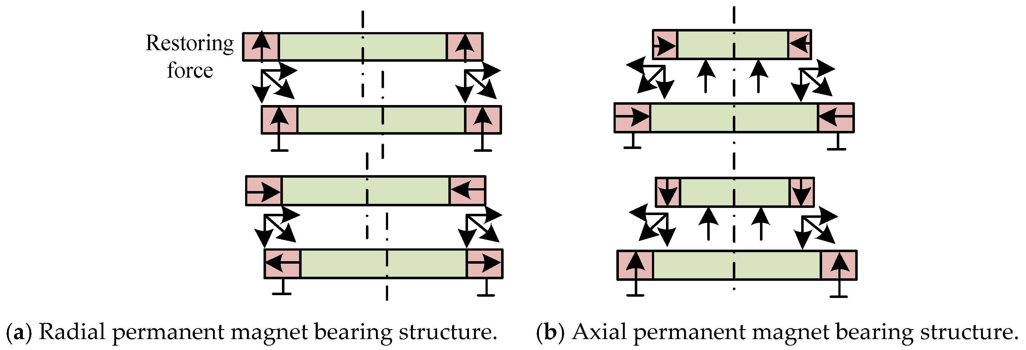
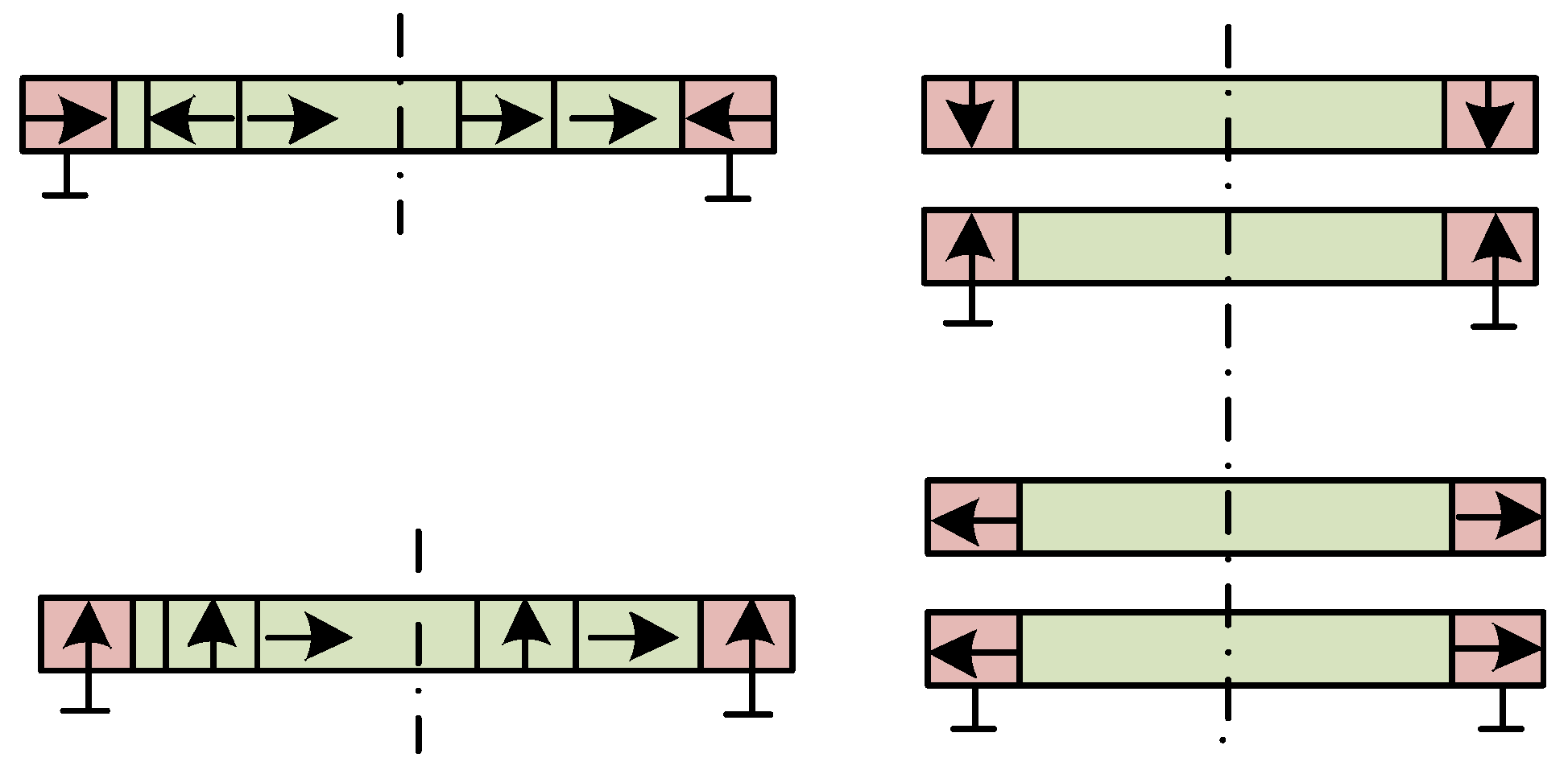
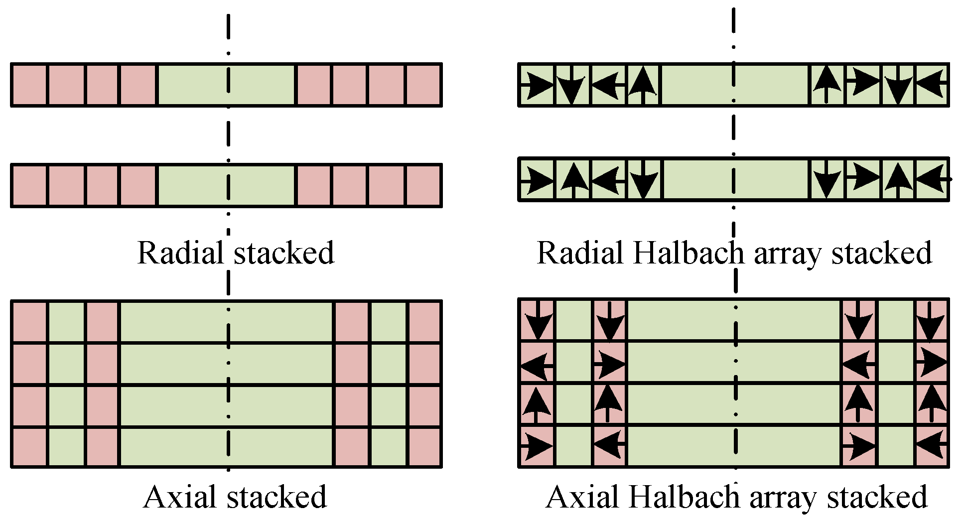
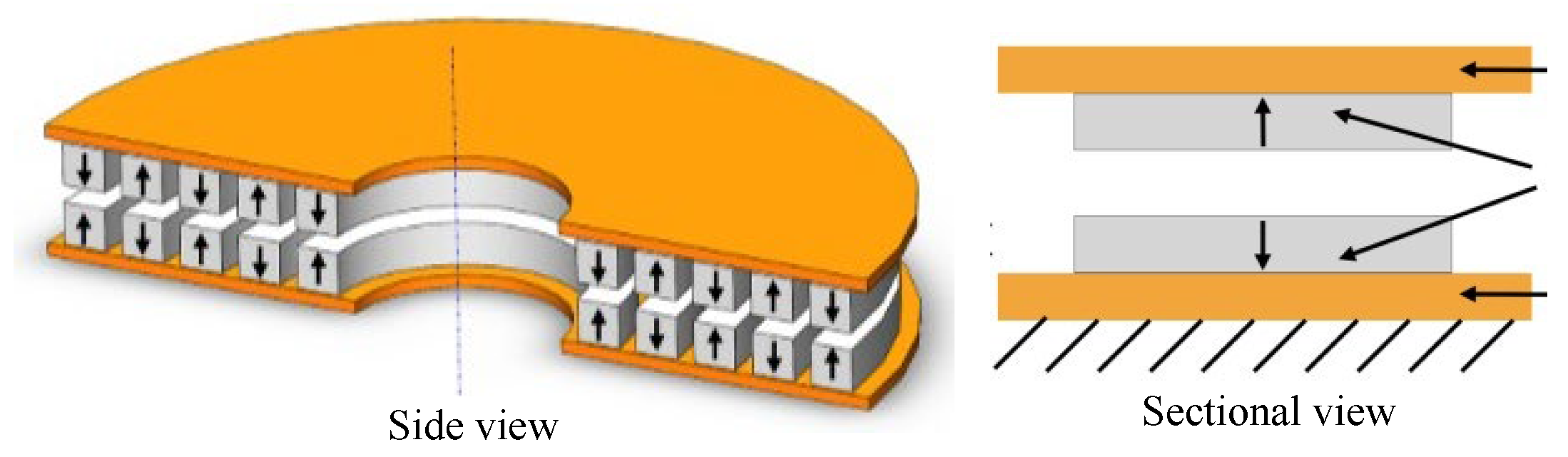
| Repulsive magnetic bearing | PMB | The rotor is suspended by repulsive forces generated by the magnetization direction arrangement of different permanent magnets, including axial array, radial array, and Halbach array. | A design similar to the suction-type permanent magnet bearing is proposed. However, this type of bearing operates by relying on the repulsive force between magnetic rings. Multiple magnetic rings need to be stacked to increase the load-bearing capacity and stiffness. |
| DMB | By using the diamagnetism and flux napping properties of superconductors or normal temperature diamagnetism materials, the magnetic field opposite to the outside world is generated, and the repulsion force is generated with the permanent magnet, so as to realize the rotor non-contact suspension magnetic bearing. | Passive and completely contactless friction, simple structure, variable stiffness, superconducting magnetic bearings require low temperature environment. Ambient diamagnetic material magnetic bearings require light load weight. | |
| Type of Magnetic Suspension Bearing | Modeling Approaches | Literature | |
|---|---|---|---|
| Suction magnetic bearing | AMB | Virtual displacement method, equivalent magnetic circuit method, Maxwell tensor method, Sub-domain method, Perturbation method, Dynamic magnetic circuit method, Distributed magnetic circuit method. | [23,46,47,48,49,50,51] |
| HMB | Equivalent magnetic circuit method, Maxwell tensor method, Considering eddy current effect to establish the mathematical model of suspension force. | [24,52,53,54] | |
| PMB | General mathematical model, Simplified mathematical model, Equivalent magnetic circuit method, Equivalent magnetic charge method. | [55,56,57,58,59] | |
| Repulsive magnetic bearing | PMB | Equivalent magnetic charge method, Equivalent current method, Fourier analysis, Finite Element analysis method, Lorentz force method. | [60,61,62] |
| DMB | Analysis of magnetic field model, Suspension force model, In-plane electromagnetic force model, Magnetic dipole method, Magnetic field image method, Finite element analysis method. | [41,42,44,63,64,65] | |
| Control Strategies | Advantages | Disadvantages | ||
|---|---|---|---|---|
| Suction Type Magnetic Bearing Control Strategies | Low Power Control Strategies | 1. Introduce a variety of nonlinear control algorithms; 2. Use the current integral term as an external loop independent control. | Reduce energy consumption, Reduce heat, Improve system efficiency, Facilitate equipment miniaturization and portability. | The control algorithm is complex, High precision of sensors is required, Stability and robustness face challenges. |
| Zero Displacement Control Strategies | 1. Current compensation; 2. Displacement voltage compensation. | High precision positioning, Reduced vibration, Fast response, Optimized system energy. | High sensor requirements, Complex control algorithms, System stability challenges, High cost. | |
| Robust Control Strategies | PID control, LQR control, Other robust control. | Strong anti-interference ability, Adaptability to parameter changes, Improve system reliability, Broaden application scenarios. | Eclectic control performance, Difficult design, conservative, Complex debugging. | |
| Sensor-less control Strategies | High-frequency signal injection method, Salient pole tracking method, Duty cycle compensation method, State observation method, Kalman filter. | Cost reduction, Anti-interference ability, Fast response speed, Avoid sensor error. | High model-dependence, Limited estimation accuracy, Difficult fault diagnosis, Complex control algorithms | |
| Repulsive Magnetic Bearing Control Strategies | PID, LMS adaptive method, Notch filter, Universal notch filter. | PID: Simple control, good robustness. LMS: Strong adaptive ability, does not depend on the exact model. NF: Strong adaptive ability, versatility, and scalability | PID: limited anti-interference ability, complex parameter setting. LMS: convergence speed contradicts steady-state accuracy. NF: High dependence on specific frequency, limited system adaptability, design and debugging difficulty. | |
Disclaimer/Publisher’s Note: The statements, opinions and data contained in all publications are solely those of the individual author(s) and contributor(s) and not of MDPI and/or the editor(s). MDPI and/or the editor(s) disclaim responsibility for any injury to people or property resulting from any ideas, methods, instructions or products referred to in the content. |
© 2025 by the authors. Licensee MDPI, Basel, Switzerland. This article is an open access article distributed under the terms and conditions of the Creative Commons Attribution (CC BY) license (https://creativecommons.org/licenses/by/4.0/).
Share and Cite
Wu, T.; Zhang, W. Review on Key Development of Magnetic Bearings. Machines 2025, 13, 113. https://doi.org/10.3390/machines13020113
Wu T, Zhang W. Review on Key Development of Magnetic Bearings. Machines. 2025; 13(2):113. https://doi.org/10.3390/machines13020113
Chicago/Turabian StyleWu, Tong, and Weiyu Zhang. 2025. "Review on Key Development of Magnetic Bearings" Machines 13, no. 2: 113. https://doi.org/10.3390/machines13020113
APA StyleWu, T., & Zhang, W. (2025). Review on Key Development of Magnetic Bearings. Machines, 13(2), 113. https://doi.org/10.3390/machines13020113