
Impact of Multiple Operating Parameters Interactions on Load Swing of Tower Cranes


Abstract
1. Introduction
- (1)
- Using the multi-body dynamics modeling method that combines physical and mathematical models, and considering the nonlinearity of the electromechanical system and the flexibility factors of the transmission mechanisms, an Electromechanical Rigid-Flexible Coupling (EMRFC) model for tower cranes has been established. This model accurately simulates the operational characteristics of tower cranes under the coupling effects of rigidity and flexibility, as well as the mechanisms affecting the swing of loads.
- (2)
- The Sobol sensitivity analysis method is applied to the analysis of the interactive mechanism of tower crane operation parameters, deriving the primary and interactive operation parameters that affect load swing. The study investigates the characteristics of how these tower crane operation parameters influence load swing.
- (3)
- This paper is the first to explicitly classify tower crane operation parameters into dominant and interactive operation parameters. The methods presented can provide a scientific evaluation for the operational range of these parameters, offering a basis for the setting of trajectory intervals for intelligent control reference input signals.
2. Modeling and Analysis Methods
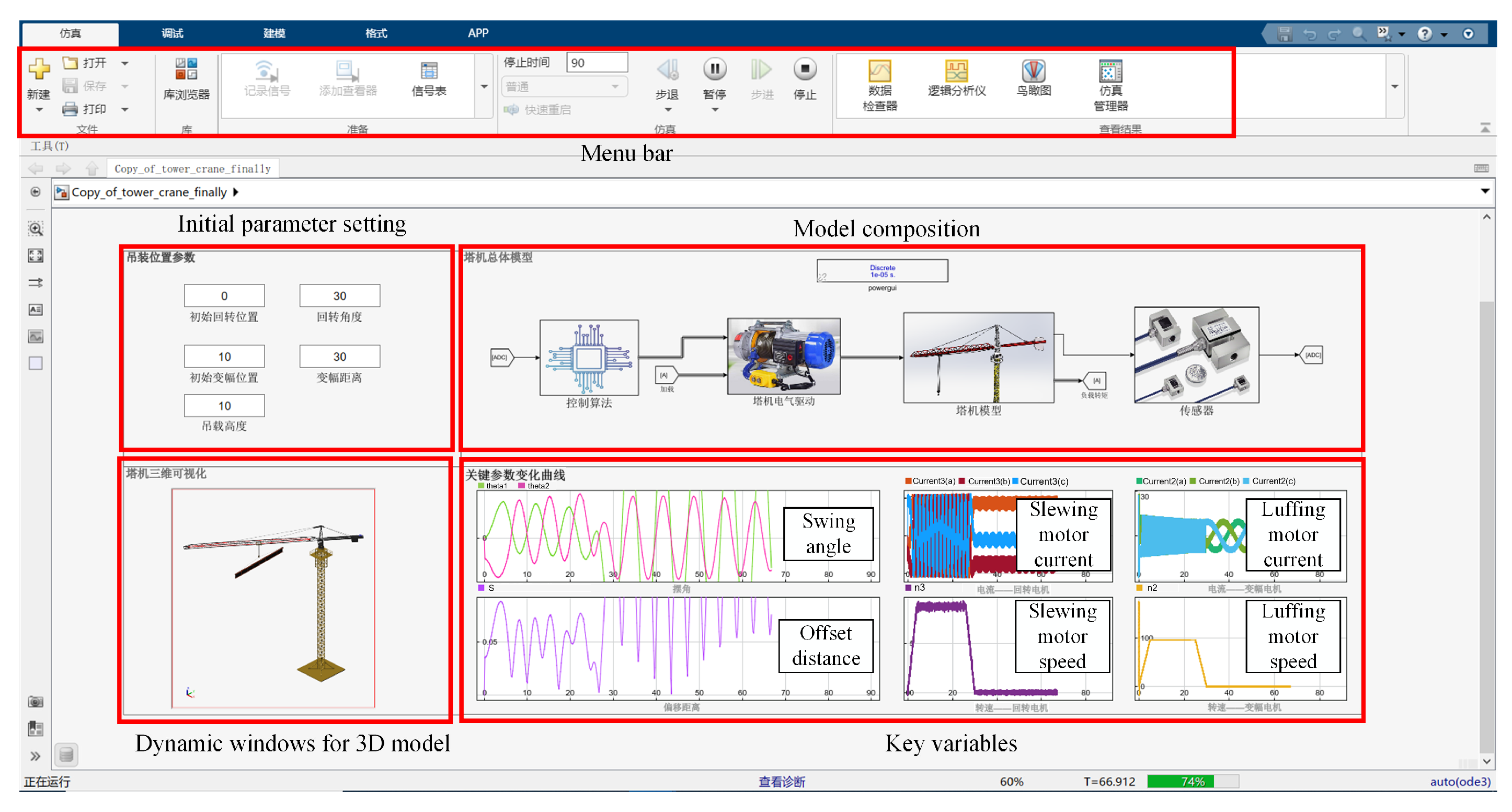
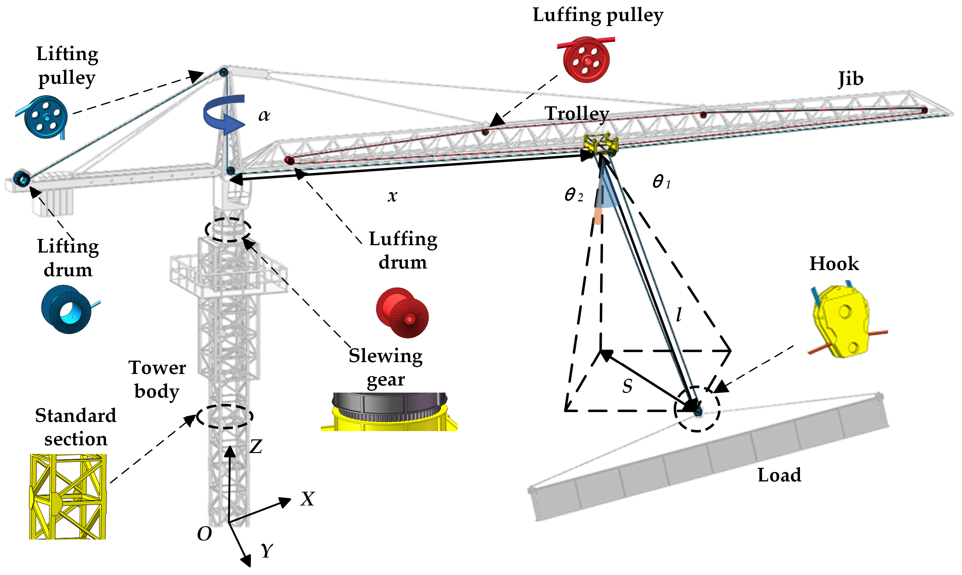
2.1. Tower Crane Modeling
- (1)
- Neglect the deformation of the boom and tower as well as the friction of the moving joints
- (2)
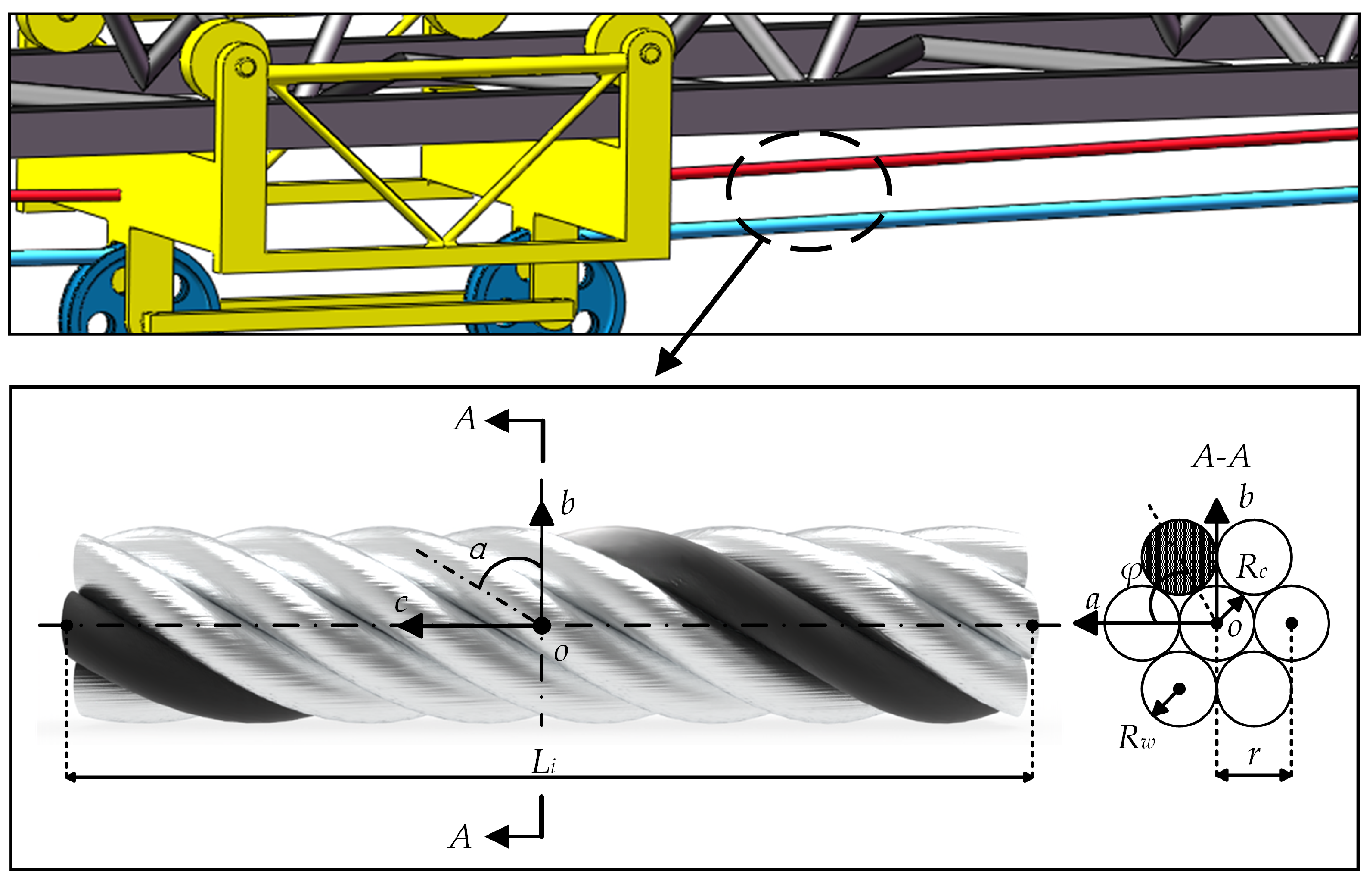
- The radial and tangential deformation of the wire rope is ignored.
- (3)
- There is no relative swing between the hook and the load.
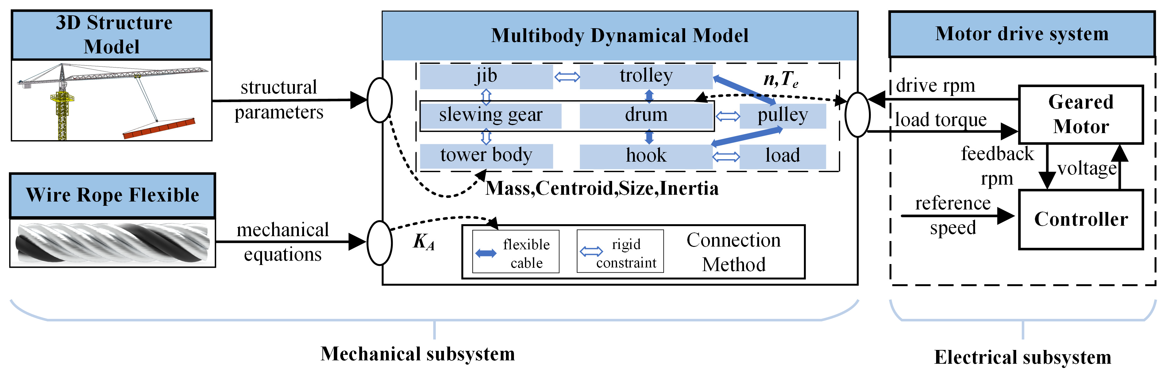
2.1.1. Mechanical Subsystem
- 3D Structure Model
- 2.
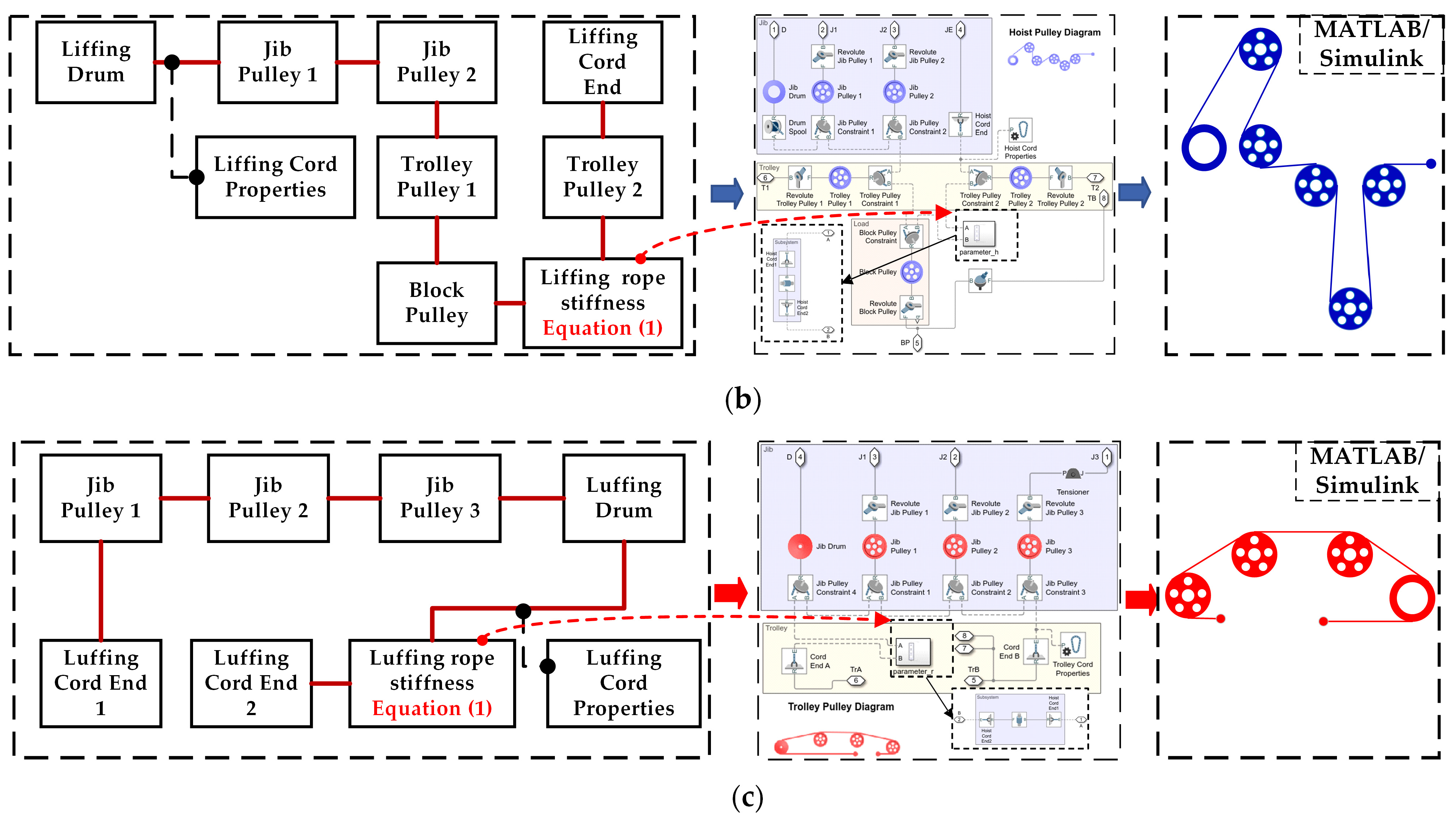
- Wire Rope Flexible
- 3.
- Multibody Dynamical Model
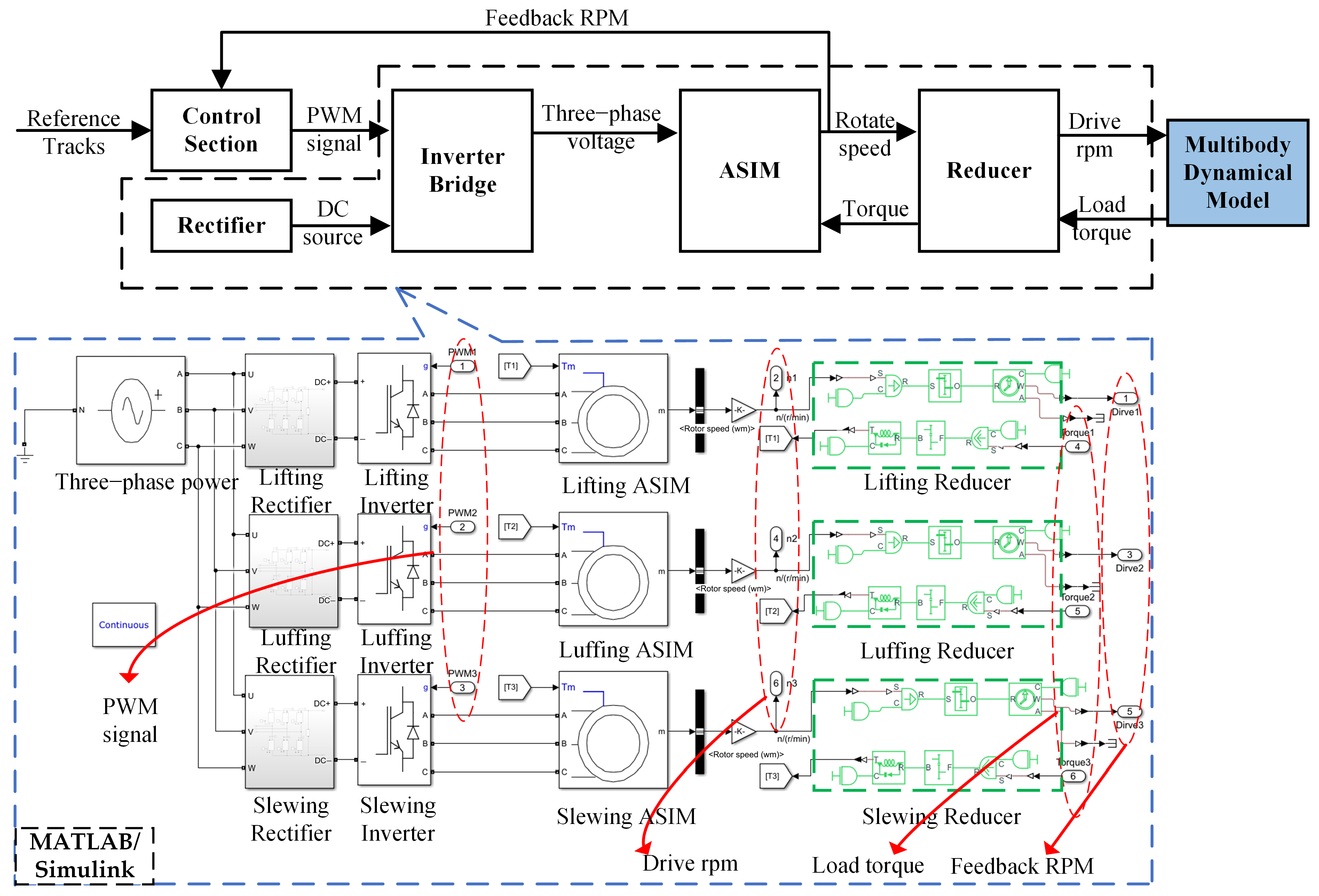
2.1.2. Electrical Subsystem
2.2. Sensitivity Analysis of Operating Parameters
3. Results and Discussion
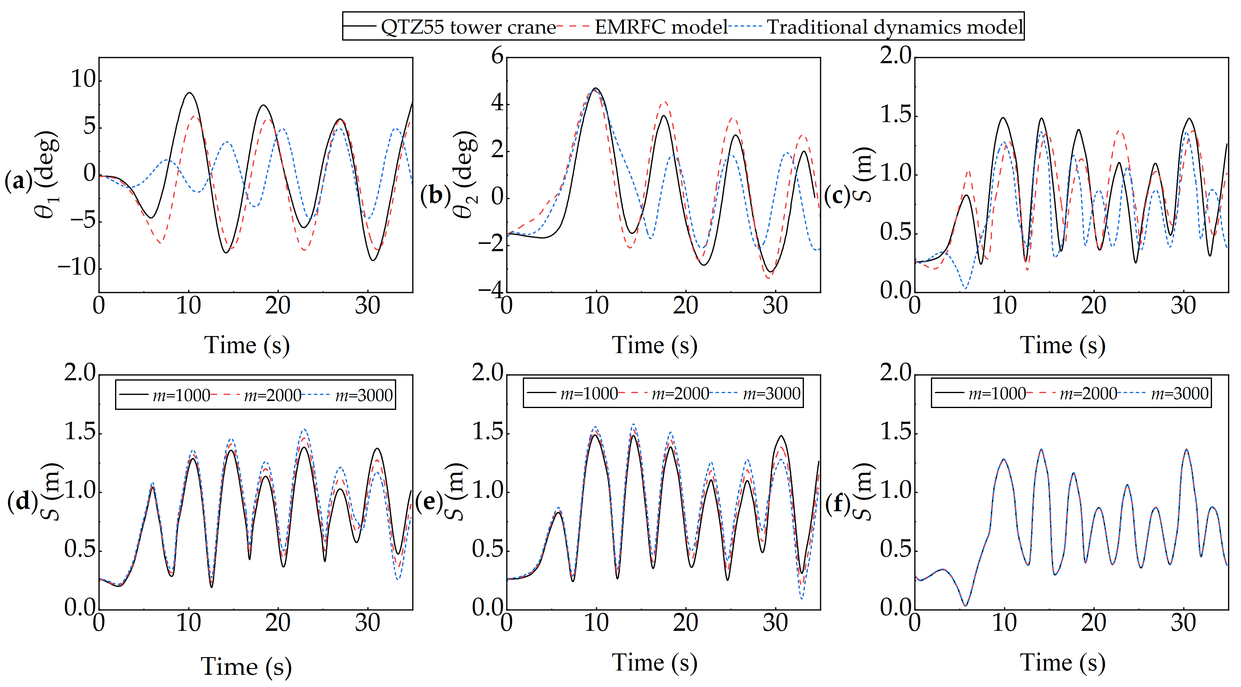
3.1. Model Validation

| Operating Parameter | Value | Unit |
|---|---|---|
| Densities | 7850 | kg/m3 |
| Yield strength | 375 | MPa |
| Tensile strength | 235 | MPa |
| Modulus of elasticity | 200 | GPa |
| Elongation | 25 | % |
| Name | Notation | Value | Unit |
|---|---|---|---|
| Carrier period | T | 10 × 10−4 | s |
| Core cross-section | Ac1, Ac2 | 3.32 × 10⁻⁵, 0.75 × 10⁻⁵ | m2 |
| Core diameter ratio | ξ | 1 | / |
| Core radius | Rc1, Rc2 | 3.25 × 10⁻³, 1.55 × 10⁻³ | m |
| Core wire cross Section | Aw1, Aw2 | 3.32 × 10⁻⁵, 0.75 × 10⁻⁵ | m2 |
| Drum Diameter | Dd | 0.254 | m |
| Drum mass | Dm | 145 | kg |
| Elastic modulus | E0 | 1.8 × 10¹¹ | Pa |
| Gear ratio | N1, N2, N3 | 15.9, 90, 195 | / |
| Helix angle | α1, α2 | 57, 62 | deg |
| Initial lifting rope Length | L1′ | 126 | m |
| Jib end distance | H1 | 57 | m |
| Jib inertia | J | 1.02 × 10⁷ | kg·m2 |
| Jib tail distance | H2 | 12.4 | m |
| Logarithmic | p1, p2, p3 | 4, 3, 3 | / |
| Luffing rope length | L2 | 183 | m |
| Moment of inertia | J1, J2, J3 | 2.2, 1.8, 3.6 | kg·m2 |
| Number of cores | N | 6 | / |
| Poisson’s ratio | ν | 0.3 | / |
| Pulley Diameter | Pd | 0.381 | m |
| Pulley mass | Pm | 18.35 | kg |
| Rated power of motor | PN1, PN2, PN3 | 5.4 × 10³, 4 × 10³, 11 × 103 | W |
| Reference length | L0 | 0.2 | m |
| Rotational damping | B1, B2, B3 | 0.0252, 0.023, 0.0852 | N·m·s/deg |
| The sum of the core radius | r1, r2 | 6.5 × 10⁻³, 3.1 × 10⁻³ | m |
| Trolley quality | M1 | 324 | kg |
| Trolley quality | M1 | 324 | kg |
| Twisting radius | Rw1, Rw2 | 3.25 × 10⁻³, 1.55 × 10⁻³ | m |
| Wire strain | εw1, εw2 | 0.0686, 0.533 | % |
| Operating Parameter | Notation | Minimum Value | Maximum Value |
|---|---|---|---|
| Luffing up-acceleration | ar1 (m/s2) | 0.1 | 0.5 |
| Luffing down-acceleration | ar2 (m/s2) | 0.1 | 0.5 |
| Luffing speed | vr (m/s) | 0.5 | 1 |
| Slewing up-acceleration | at1 (deg/s2) | 0.5 | 2.5 |
| Slewing down-acceleration | at2 (deg/s2) | 0.5 | 2.5 |
| Slewing speed | vt (deg/s) | 2 | 4 |
| Lifting height | l (m) | 10 | 30 |
| Load mass | m (kg) | 1000 | 3000 |
3.2. Impact of Flexible Transmission Characteristics on Load Swing
3.3. Impact of Operating Parameters on Load Swing
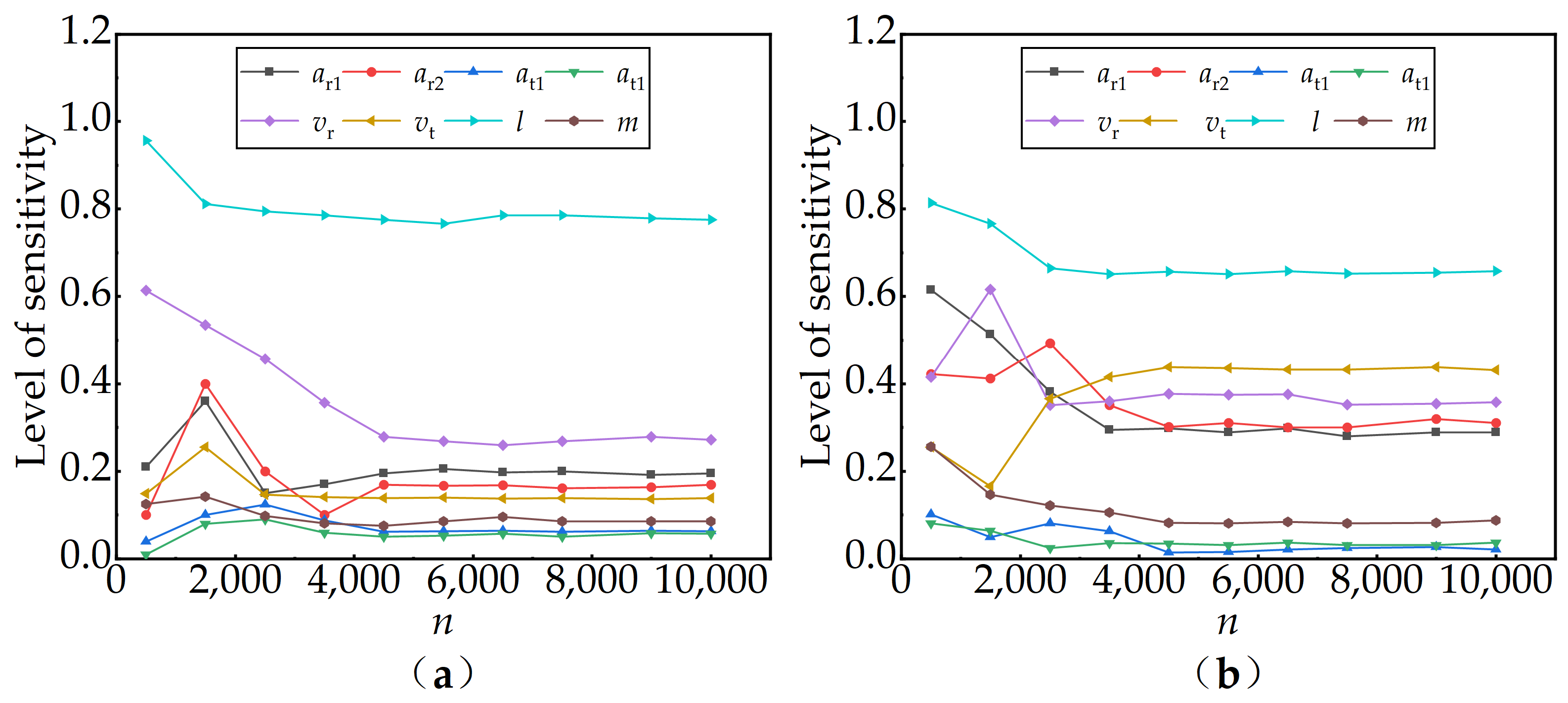
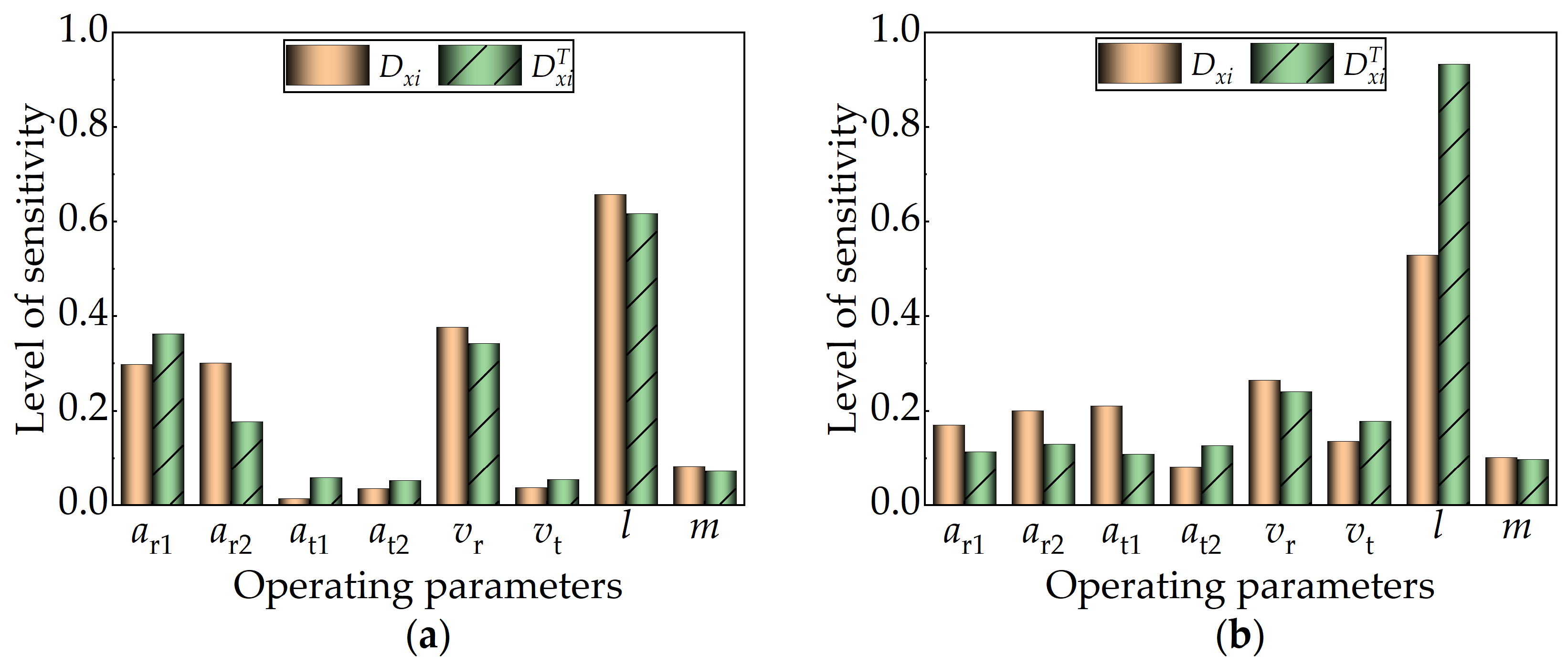
3.3.1. Sensitivity Analysis of Operating Parameters on Load Swing
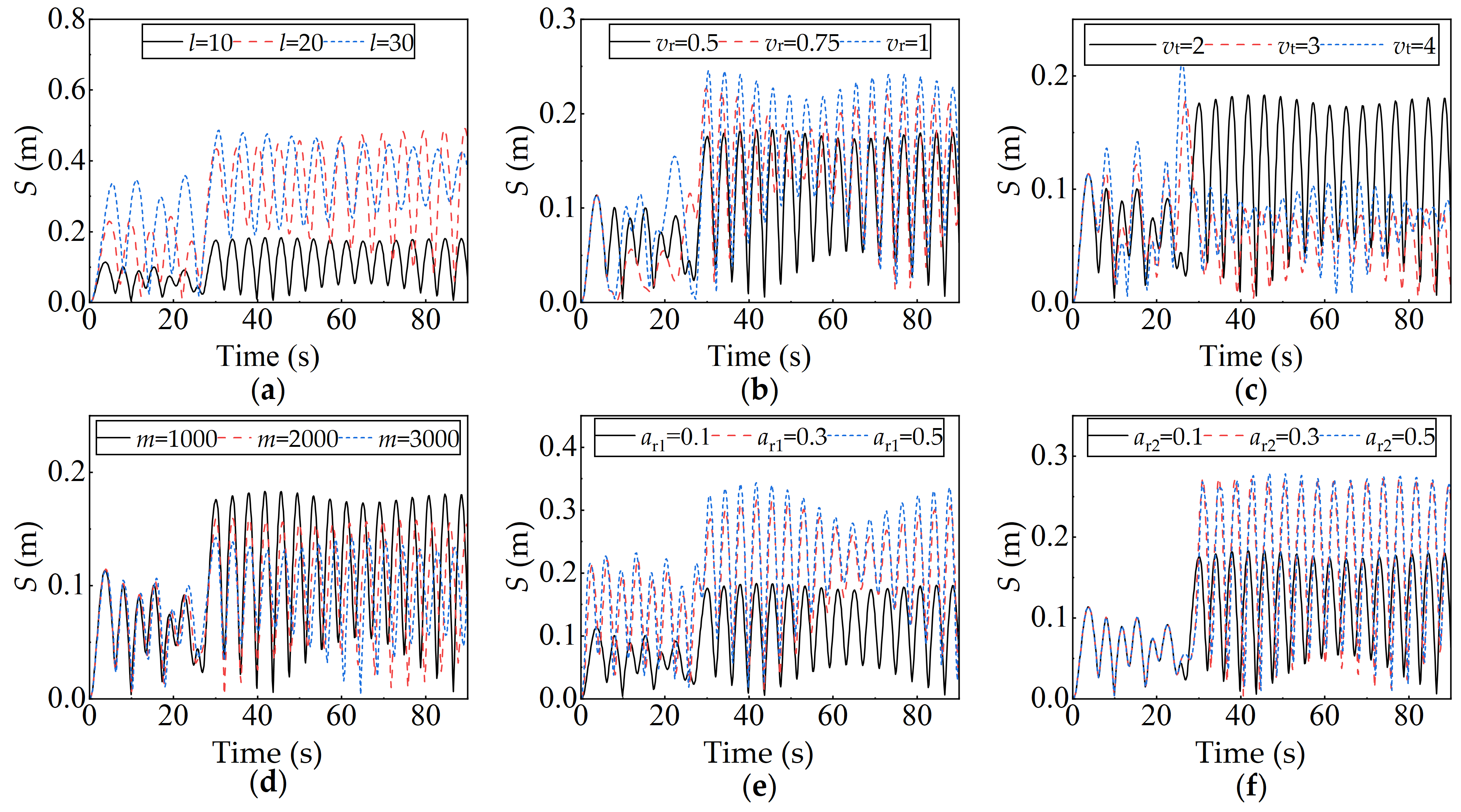
3.3.2. Impact of Dominant Operating Parameters on Load Swing
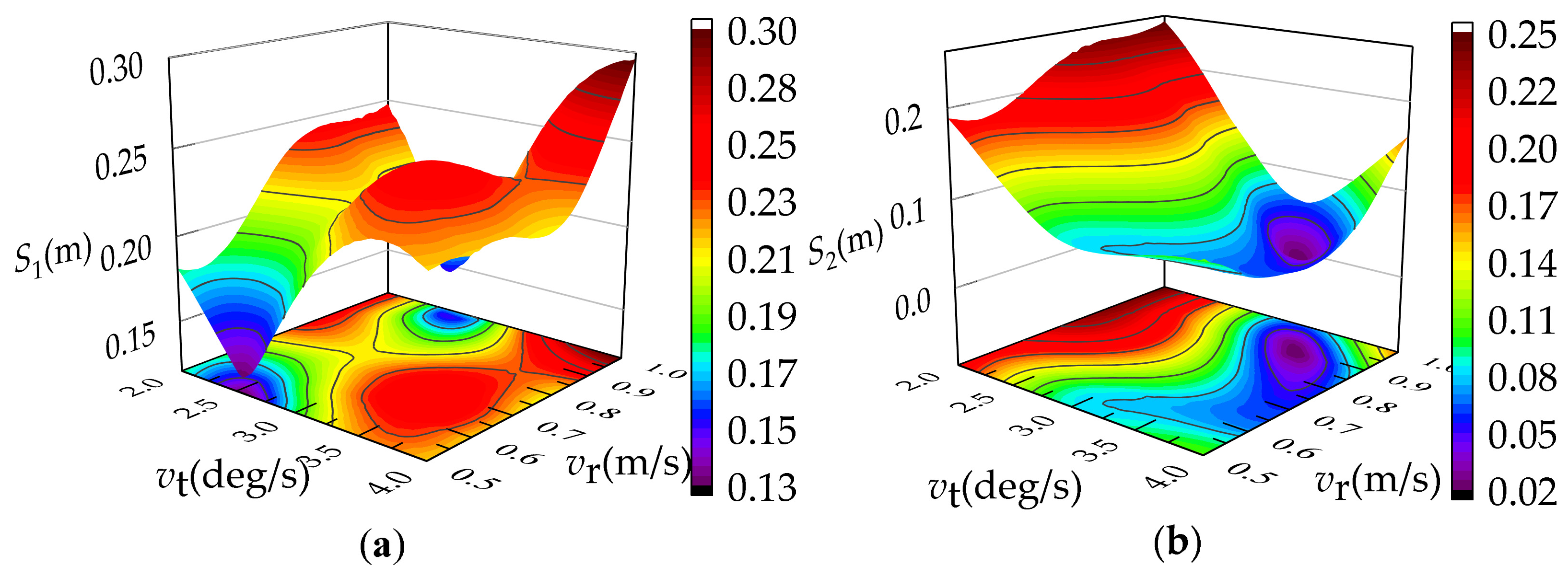
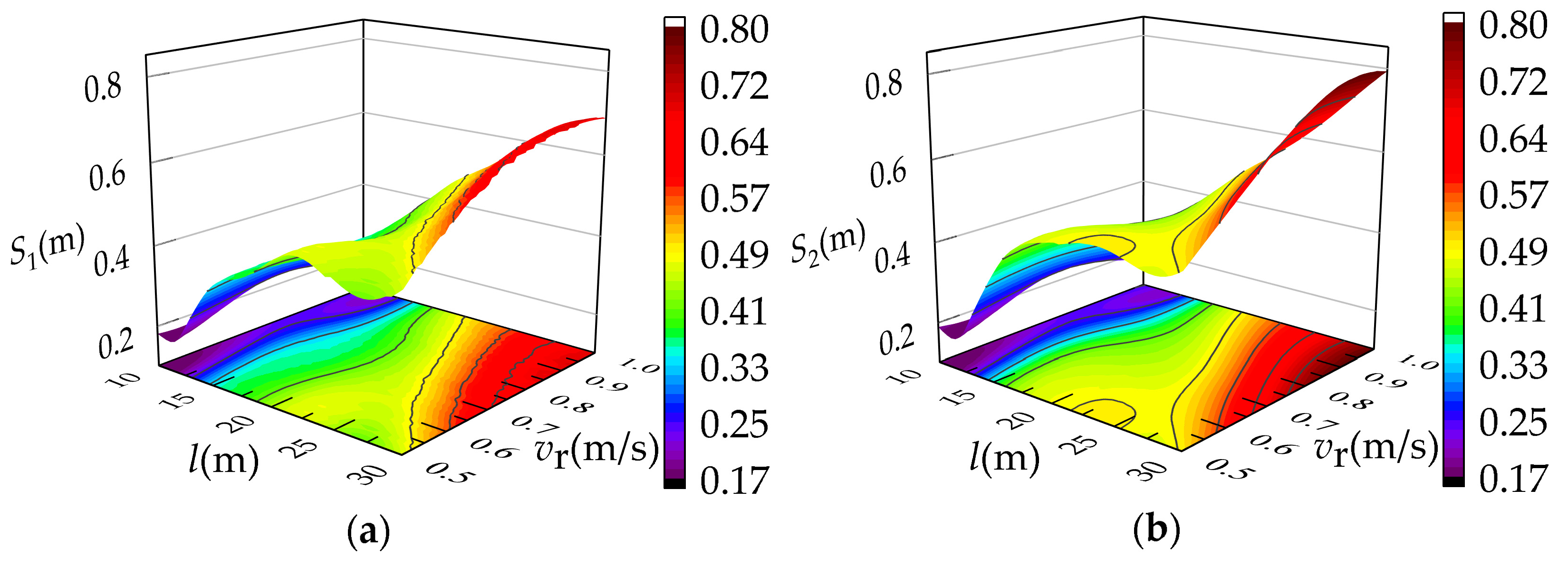
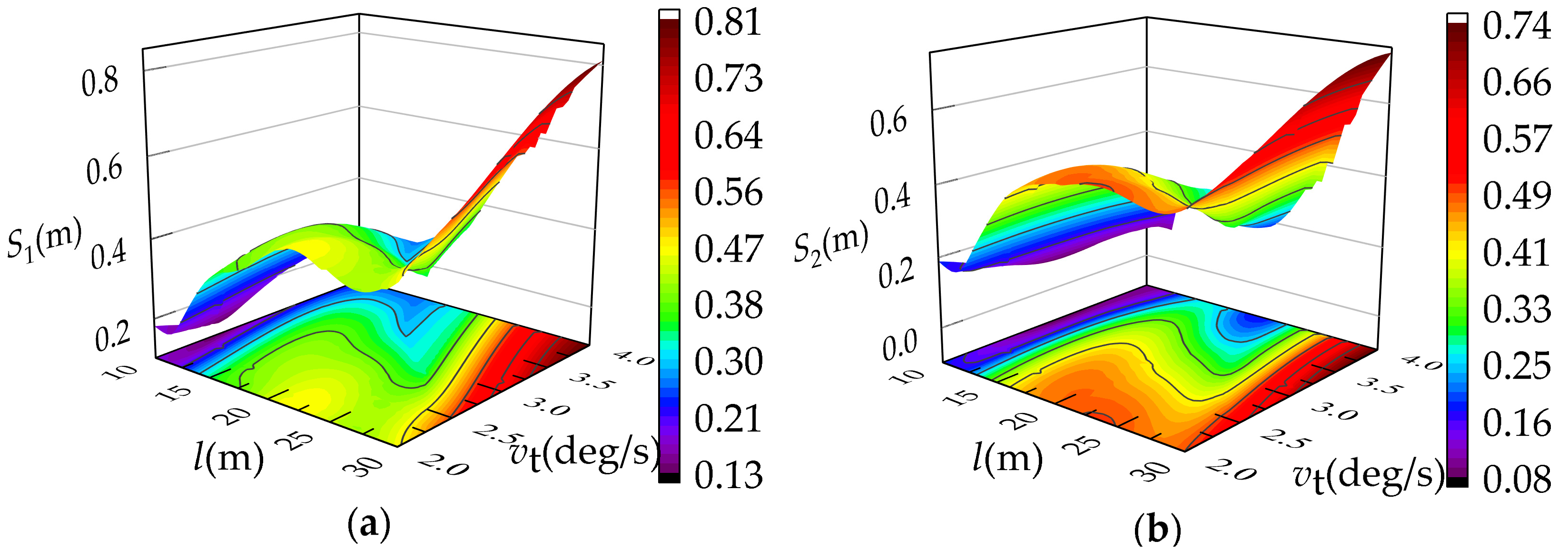
3.3.3. Impact of Interactive Operating Parameters on Load Swing
4. Conclusions
- This paper takes multibody dynamics as a bridge to effectively couple electric drive, mechanical structure, and flexible transmission, and establishes the EMRFC model for the QTZ55 tower crane. The model accurately describes the nonlinear effects of the rigid-flexible coupling and electromechanical coupling on the load swing of the tower crane, and the modular modeling makes the model easy to extend.
- The elasticity of the wire rope of the flexible drive mechanism affects the swing amplitude of the load, and the swing amplitude of the load in the running and stopping phases increases and decreases, respectively, when the mass of the load is increased. In addition, the amplitude of the load swing increases as the modulus of elasticity of the wire rope increases, and a “beat vibration” phenomenon is commonly observed during the stopping phase.
- The interaction among the lifting height, slewing speed, and luffing speed has a significant effect on the load offset distance; the offset distance shows a complex trend with the increase of the slewing speed and luffing speed, and shows a step change trend with the increase of the lifting height.
- The reasonable ranges for various operating parameters of the tower crane are given under the composite working conditions. Setting the operating parameters ar1 and ar2 as 0.1 m/s2, at1 and at2 as 0.5~2.5 deg/s2, l as 10~15 m, vr as [0.5~0.6 m/s, 0.9~1.0 m/s], m as 1000~3000 kg, and vt as 2.5~3.0 deg/s, the offset distance can be limited to 0.2 m.
Author Contributions
Funding
Data Availability Statement
Conflicts of Interest
Appendix A
References
- Hu, S.; Fang, Y.; Bai, Y. Automation and optimization in crane lift planning: A critical review. Adv. Eng. Inform. 2021, 49, 101346. [Google Scholar] [CrossRef]
- Ramli, L.; Mohamed, Z.; Abdullahi, A.M.; Jaafar, H.; Lazim, I. Control strategies for crane systems: A comprehensive review. Mech. Syst. Signal. PR. 2017, 95, 1–23. [Google Scholar] [CrossRef]
- Zheng, Z.; Wang, F.; Gong, G.; Han, D. Intelligent technologies for construction machinery using data-driven methods. Automat. Constr. 2023, 147, 104711. [Google Scholar] [CrossRef]
- Zhu, H.; Hwang, B.; Asce, M.; Ngo, J.; Tan, J. Applications of smart technologies in construction project management. J. Constr. Eng. M. 2022, 148, 0002260. [Google Scholar] [CrossRef]
- Kolawach, C.; Shuichiro, H.; Hiroshi, Y. Vibration reduction of the rotary crane with flexible boom. J. Mech. Eng. 2022, 9, 22–31. [Google Scholar]
- Tong, Z.; Wu, W.; Guo, B.; Zhang, J.; He, Y. Cargo swing analysis and swing angle optimization of flat-top tower cranes. J. Vib. Eng. Technol. 2023, 12, 4715–4727. [Google Scholar] [CrossRef]
- Jiang, W.; Ding, L.; Zhou, C. Digital twin: Stability analysis for tower crane hoisting safety with a scale model. Automat. Constr. 2022, 138, 104257. [Google Scholar] [CrossRef]
- Montonen, J.H.; Nevaranta, N.; Niemelä, M.; Lindh, T. Comparison of extrainsensitive input shaping and swing-angle-estimation-based slew control approaches for a tower crane. Appl. Sci. 2022, 12, 5945. [Google Scholar] [CrossRef]
- Liu, F.; Yang, J.; Wang, J.; Liu, C. Swing characteristics and vibration feature of tower cranes under compound working Condition. Shock. Vib. 2021, 2021, 8997396. [Google Scholar] [CrossRef]
- Liu, F.; Yang, J.; Wang, J.; Liu, C.D.; Liu, C. Effect on tower crane structural vibration under the lifting-luffing coupling condition. J. Mech. Sci. Technol. 2023, 37, 4935–4947. [Google Scholar] [CrossRef]
- Peng, J.; Huang, J.; Singhose, W. Payload twisting dynamics and oscillation suppression of tower cranes during slewing motions. Nonlinear. Dyn. 2019, 98, 1041–1048. [Google Scholar] [CrossRef]
- Cao, X.; Yang, Y.; Wang, W.; Gu, Z. Rigid-Flexible coupling dynamic modeling of a tower crane with long flexible boom. Mech. Mach. Sci. 2017, 55, 39–57. [Google Scholar]
- Cheng, B.; Yang, B.; Wang, D.; Duan, M. Finite element analysis of complete structure of tower cranes. J. Phys. Conf. Ser. 2023, 2419, 012004. [Google Scholar] [CrossRef]
- Zhang, M.; Zhang, Y.; Ji, B.; Ma, C.; Cheng, X. Modeling and energy-based sway reduction control for tower crane systems with double-pendulum and spherical-pendulum effects. Meas. Control 2020, 53, 141–150. [Google Scholar] [CrossRef]
- Feng, R.; Zhang, E.; Dong, M. Jib vibration and payload swing of tower cranes in the case of trolley motion. Arab. J. Sci. Eng. 2021, 46, 12179–12191. [Google Scholar] [CrossRef]
- Li, K.; Liu, M.; Yu, Z.; Lan, P.; Lu, N. Multibody system dynamic analysis and payload swing control of tower crane. Proc. Inst. Mech. Eng. Part K J. Multi-Body Dyn. 2022, 236, 407–421. [Google Scholar] [CrossRef]
- Florentin, R.; Oliver, S. Modeling and control of tower cranes with elastic structure. IEEE. Trans. Control Syst. Technol. 2020, 236, 64–79. [Google Scholar]
- Zhou, Y.; Meng, Z. An improved negative zero vibration anti-swing control strategy for grab ship unloader based on elastic wire rope model. Mec. Ind. 2021, 22, 45. [Google Scholar]
- Gu, J.; Qin, Y.; Xia, Y.; Jiao, Q. Research on dynamic characteristics of composite towering structure. Int. J. Appl. Mech. 2021, 13, 2150096. [Google Scholar] [CrossRef]
- Wei, Y.; Hu, T.; Yue, P.; Luo, W.; Ma, S. Study on the construction theory of digital twin mechanism model for mechatronics equipment. Int. J. Adv. Manuf. Tech. 2022, 131, 5383–5401. [Google Scholar] [CrossRef]
- Jiao, Q.; Li, B.; Qin, Y.; Wang, F.; Gu, J.; Wang, J.; Mi, C. Research on dynamic characteristics of lifting rope-breaking for the nuclear power crane. J. Fail. Anal. Prev. 2021, 21, 1220–1230. [Google Scholar] [CrossRef]
- Shi, H.; Tao, F.; Tong, S.; Tang, Y.; Han, G. Research on nonlinear coupled tracking controller for double pendulum gantry cranes with load hoisting/lowering. Nonlinear Dyn. 2022, 108, 223–238. [Google Scholar] [CrossRef]
- Viacheslav, L.; Yuriy, R.; Liubov, S.; Yuriy, L. The dynamic analysis of the joint trolley movement and hoisting mechanism in the tower crane. Strength Mater. Theory Struct. 2022, 108, 267–282. [Google Scholar]
- De Menezes, E.A.W.; Marczak, R.J. Comparative analysis of different approaches for computing axial, torsional and bending stiffnesses of cables and wire ropes. Eng. Struct. 2021, 241, 112487. [Google Scholar] [CrossRef]
- Pozzi, M.; Achilli, G.; Valigi, M.; Malvezzi, M. Modeling and simulation of robotic grasping in simulink through simscape multibody. Front. Robot. AI. 2022, 9, 873558. [Google Scholar] [CrossRef] [PubMed]
- Boschetti, G.; Sinico, T. Designing digital twins of robots using simscape multibody. Robotics 2024, 13, 62. [Google Scholar] [CrossRef]
- Mao, Z.; Luo, Y.; Zhou, S. The multi-objective optimisation design of outlet guide vanes of diagonal flow fan based on Sobol sensitivity analysis. Proc. Inst. Mech. Eng. Part A J. Power Energy 2024, 238, 382–400. [Google Scholar] [CrossRef]
- Zhou, R.; Feng, W.; Deng, Z.; Gao, H.; Ding, L.; Li, N. Parameter sensitivity analysis and main parameter estimation of wheel-ground mechanical model. Chin. J. Aeronauts. 2021, 42, 253–265. [Google Scholar]
- Tian, Z.; Yu, L.; Huimin, O.; Zhang, G. Swing suppression control in tower cranes with time-varying rope length using real-time modified trajectory planning. Automat. Constr. 2021, 132, 103954. [Google Scholar] [CrossRef]
- Liu, X. Study on the Vibration Characteristics of Crane Arm Under Slewing Condition of Tower Crane. Master’s Thesis, Shandong Jianzhu University, Jinan, China, 2023. [Google Scholar]
- Qin, Z.; Huang, Q.; Jin, H.; Xue, H. Simulation of multi-body dynamics and strand stress analysis of hoisting wire rope. J. Notrhwest. Polytechnical. Univ. 2020, 38, 485–493. [Google Scholar] [CrossRef]


| Model | The Average Error of Radial Swing Angle/% | The Average Error of Tangential Swing Angle/% | The Average Error of Offset Distance/% |
|---|---|---|---|
| EMRFC | 7.2 | 1.17 | 2.81 |
| Traditional dynamics model | 15.2 | 1.8 | 8.3 |
| Operating Parameter | Average Local Index/ | ||
|---|---|---|---|
| l | 0.64 | 0.79 | 0.15 |
| vr | 0.25 | 0.31 | 0.07 |
| vt | 0.09 | 0.17 | 0.08 |
| ar1 | 0.17 | 0.16 | 0.01 |
| ar2 | 0.15 | 0.14 | 0.01 |
| m | 0.06 | 0.07 | 0.01 |
| at1 | 0.08 | 0.05 | 0.03 |
| at2 | 0.06 | 0.05 | 0.01 |
| Operating Parameter | Value | Running Phase | Stopping Phase | |||
|---|---|---|---|---|---|---|
| Maximum Offset Distance/m | Period/s | Maximum Offset Distance/m | Period/s | Period of Beat Vibration/s | ||
| l (m) | 10 | 0.12 | 6.34 | 0.18 | 6.34 | 50 |
| 20 | 0.24 | 7.92 | 0.44 | 8.03 | 50 | |
| 30 | 0.35 | 10.05 | 0.49 | 10.02 | 50 | |
| vr (m/s) | 0.5 | 0.12 | 6.34 | 0.18 | 6.34 | 50 |
| 0.75 | 0.12 | 6.18 | 0.23 | 6.12 | 50 | |
| 1.0 | 0.16 | 6.27 | 0.26 | 6.15 | 50 | |
| vt (deg/s) | 2 | 0.12 | 6.34 | 0.18 | 6.34 | 50 |
| 3 | 0.17 | 6.51 | 0.82 | 6.31 | 40 | |
| 4 | 0.23 | 6.48 | 0.11 | 6.33 | 30 | |
| ar1 (m/s2) | 0.1 | 0.12 | 6.34 | 0.18 | 6.34 | 50 |
| 0.3 | 0.22 | 5.68 | 0.32 | 6.31 | 50 | |
| 0.5 | 0.23 | 5.84 | 0.35 | 6.37 | 50 | |
| ar2 (m/s2) | 0.1 | 0.12 | 6.34 | 0.18 | 6.34 | 50 |
| 0.3 | 0.12 | 6.34 | 0.27 | 6.32 | 50 | |
| 0.5 | 0.12 | 6.34 | 0.28 | 6.31 | 50 | |
| m (kg) | 1000 | 0.12 | 6.34 | 0.18 | 6.34 | 50 |
| 2000 | 0.13 | 6.33 | 0.13 | 6.31 | 45 | |
| 3000 | 0.14 | 6.34 | 0.11 | 6.29 | 40 | |
Disclaimer/Publisher’s Note: The statements, opinions and data contained in all publications are solely those of the individual author(s) and contributor(s) and not of MDPI and/or the editor(s). MDPI and/or the editor(s) disclaim responsibility for any injury to people or property resulting from any ideas, methods, instructions or products referred to in the content. |
© 2025 by the authors. Licensee MDPI, Basel, Switzerland. This article is an open access article distributed under the terms and conditions of the Creative Commons Attribution (CC BY) license (https://creativecommons.org/licenses/by/4.0/).
Share and Cite
Liu, P.; Zhao, C.; Sun, Y.; Zhang, X. Impact of Multiple Operating Parameters Interactions on Load Swing of Tower Cranes. Machines 2025, 13, 85. https://doi.org/10.3390/machines13020085
Liu P, Zhao C, Sun Y, Zhang X. Impact of Multiple Operating Parameters Interactions on Load Swing of Tower Cranes. Machines. 2025; 13(2):85. https://doi.org/10.3390/machines13020085
Chicago/Turabian StyleLiu, Peijin, Chong Zhao, Yu Sun, and Xinhui Zhang. 2025. "Impact of Multiple Operating Parameters Interactions on Load Swing of Tower Cranes" Machines 13, no. 2: 85. https://doi.org/10.3390/machines13020085
APA StyleLiu, P., Zhao, C., Sun, Y., & Zhang, X. (2025). Impact of Multiple Operating Parameters Interactions on Load Swing of Tower Cranes. Machines, 13(2), 85. https://doi.org/10.3390/machines13020085