Multi-Objective Optimization of Independent Automotive Suspension by AI and Quantum Approaches: A Systematic Review


Abstract
1. Introduction
- x = design variable vector (suspension geometric parameters);
- = objective function vector;
- = inequality constraints;
- = equality constraints;
- n = number of objective functions ;
- m = number of inequality constraints;
- p = number of equality constraints.
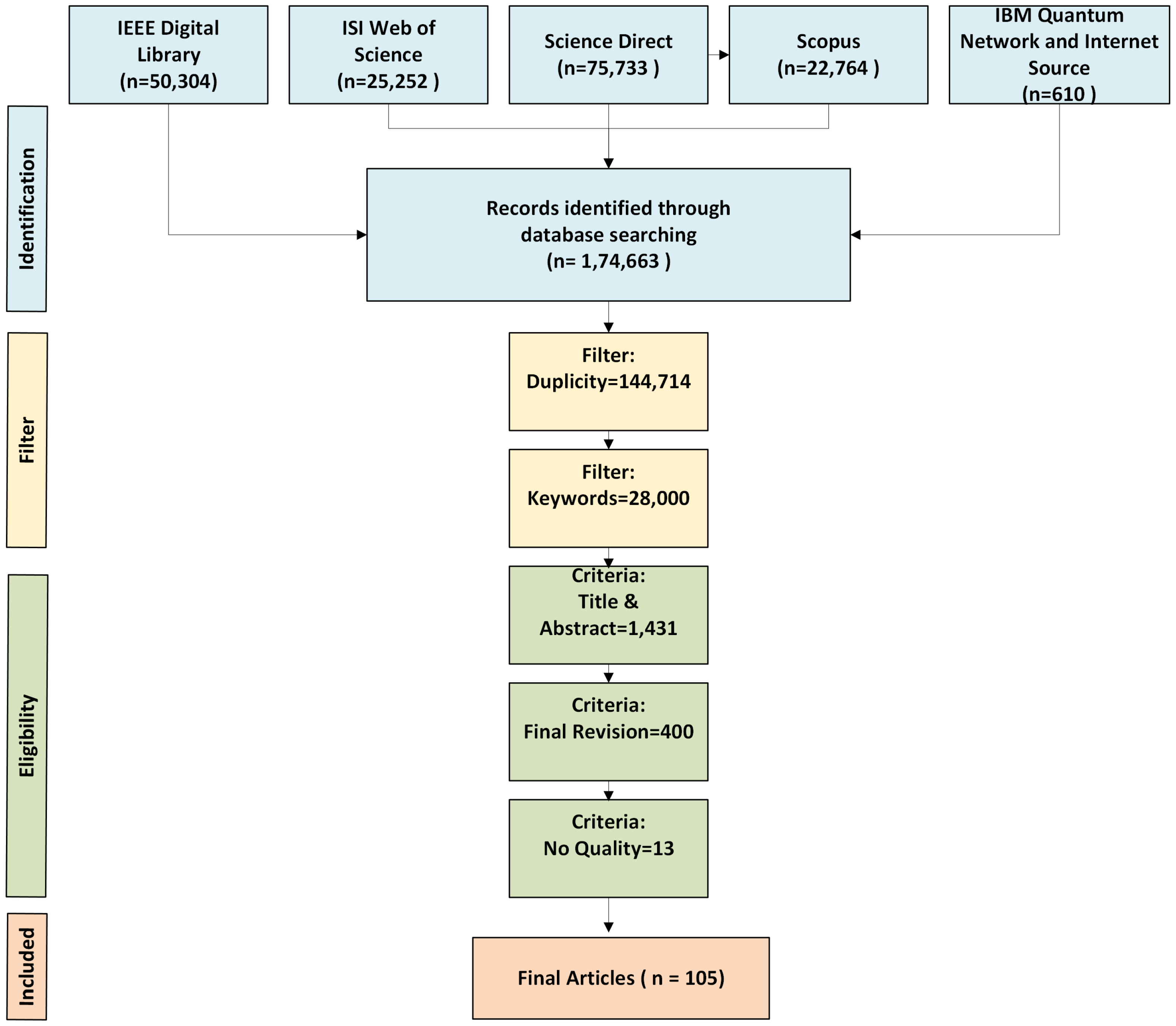
1.1. Literature Search

| Search Query | Database | Total Papers |
|---|---|---|
| Fields Searched: All fields | Scopus | 22,764 |
| Search Connectors: AND, OR | IEEE Xplore | 50,304 |
| - AND: “Optimization” AND “Algorithm” | Science Direct | 75,733 |
| - OR: “Independent” AND “Suspension” | Web of Science | 25,252 |
| - OR: “Quantum” AND “Algorithm” | IBM Quantum Research & Internet Source | 610 |
| - OR: “Artificial” AND “Intelligence” | ||
| - AND: “Automotive” |

1.2. Research Questions
- provide a systematic review of the state of the art of independent suspension systems;
- analyze the problems of toe, camber, and caster parameters;
- compare the most common optimization methods, including particle swarm optimization (PSO), genetic algorithms, gradient descent, and ant colony optimization;
- Investigate the potential of applying quantum computing in suspension system design and optimization.
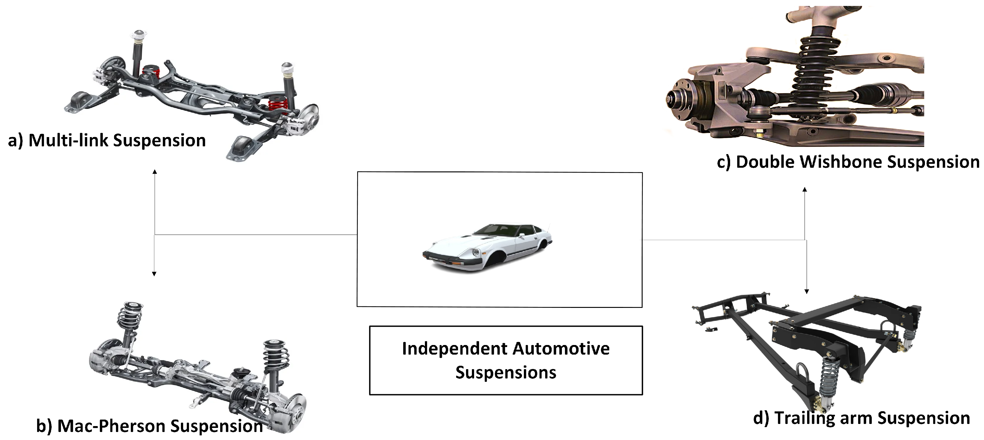
2. Independent Automotive Suspension
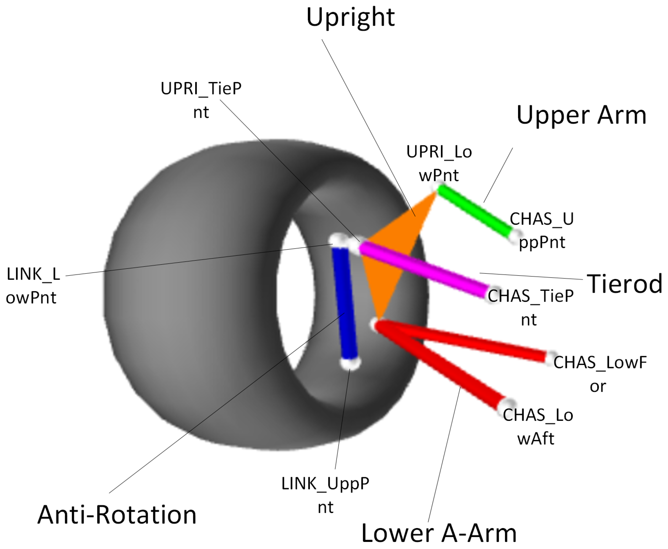
2.1. Multi-Link Suspension
| Point Name | X (mm) | Y (mm) | Z (mm) |
|---|---|---|---|
| CHAS_LowFor | 49.000 | 405.000 | 165.000 |
| CHAS_LowAft | −240.000 | 382.000 | 114.000 |
| UPRI_LowPnt | 18.000 | 728.000 | 233.000 |
| CHAS_UppPnt | 16.000 | 462.000 | 402.000 |
| UPRI_UppPnt | 61.000 | 632.000 | 505.000 |
| LINK_LowPnt | −73.000 | 727.000 | 169.000 |
| LINK_UppPnt | −120.000 | 717.000 | 381.000 |
| CHAS_TiePnt | −190.000 | 423.000 | 289.000 |
| UPRI_TiePnt | −200.000 | 635.000 | 368.000 |
| Wheels | |||
| Half Track | 870.000 | - | - |
| Longitudinal Offset | 0.000 | - | - |
| Static Camber | 0.000° (degree) | - | - |
| Static Toe | 0.000° (degree) | - | - |
| Rim Diameter | 381.000 | - | - |
| Tire Diameter | 580.000 | - | - |
| Tire Width | 254.000 | - | - |
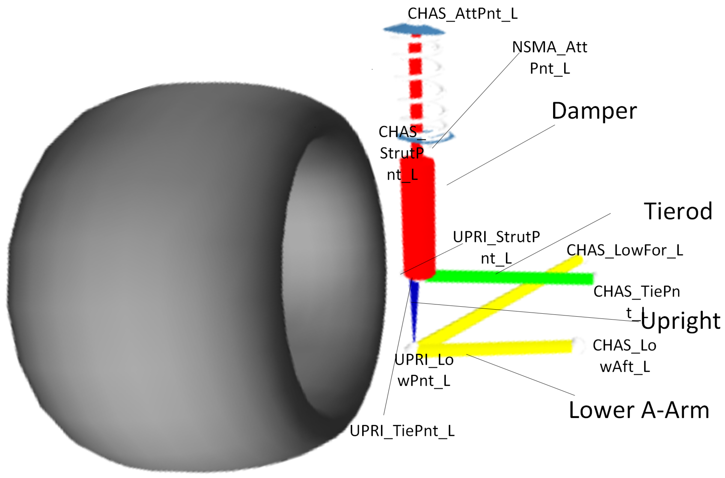
2.2. MacPherson Suspension
| Point Name | X (mm) | Y (mm) | Z (mm) |
|---|---|---|---|
| MacPherson Suspension Points | |||
| CHAS_LowFor_L | 8.790 | 379.040 | 135.290 |
| CHAS_LowAft_L | −293.000 | 356.000 | 200.000 |
| CHAS_StrutPnt_L | 58.000 | 600.000 | 676.000 |
| UPRI_LowPnt_L | −24.000 | 660.000 | 127.000 |
| UPRI_StrutPnt_L | −4.000 | 635.000 | 283.000 |
| CHAS_TiePnt_L | −111.000 | 333.385 | 219.100 |
| UPRI_TiePnt_L | −151.700 | 684.810 | 221.730 |
| Spring | |||
| NSMA_AttPnt_L | 41.000 | 600.000 | 512.000 |
| CHAS_AttPnt_L | 58.000 | 600.000 | 676.000 |
| Wheels | |||
| Half Track | 870.000 | - | - |
| Longitudinal Offset | 0.000 | - | - |
| Static Camber | 0.000° (degree) | - | - |
| Static Toe | 0.000° (degree) | - | - |
| Rim Diameter | 381.000 | - | - |
| Tire Diameter | 580.000 | - | - |
| Tire Width | 254.000 | - | - |
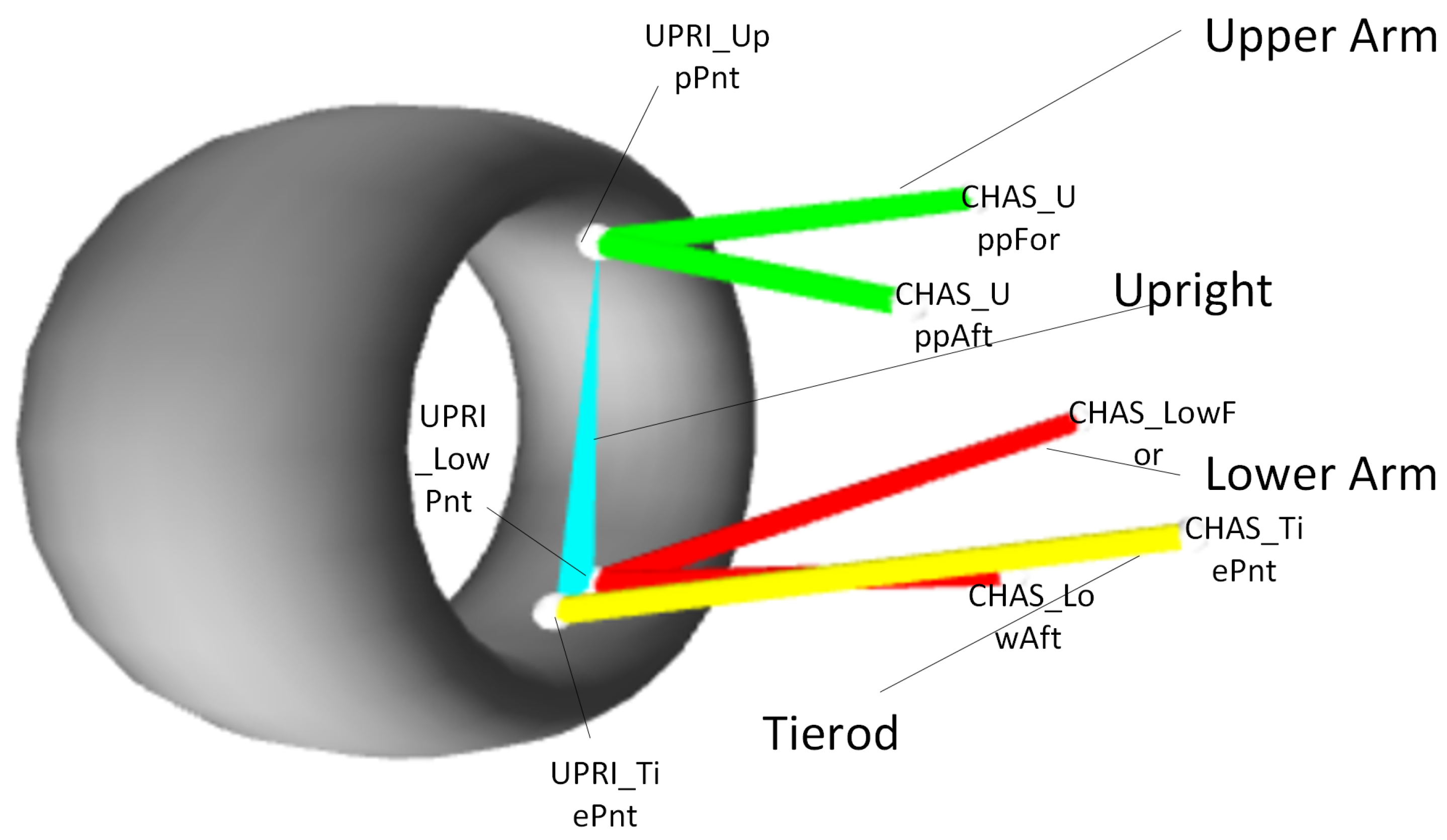
2.3. Double Wishbone Suspension
| Point Name / Parameter | X (mm) | Y (mm) | Z (mm) |
|---|---|---|---|
| Double A-Arm | |||
| CHAS_LowFor | 30.000 | 390.000 | 160.000 |
| CHAS_LowAft | −250.000 | 390.000 | 162.000 |
| CHAS_UppFor | 0.000 | 450.000 | 430.000 |
| CHAS_UppAft | −250.000 | 470.000 | 432.000 |
| UPRI_LowPnt | 47.000 | 780.000 | 150.000 |
| UPRI_UppPnt | −45.000 | 730.000 | 460.000 |
| CHAS_TiePnt | 68.326 | 208.026 | 238.252 |
| UPRI_TiePnt | 133.858 | 750.000 | 191.262 |
| Direct CoilOver | |||
| NSMA_AttPnt_L | −200.000 | 650.000 | 450.000 |
| CHAS_AttPnt_L | −250.000 | 450.000 | 700.000 |
| Wheels | |||
| Half Track | 870.000 | - | - |
| Longitudinal Offset | 0.000 | - | - |
| Static Camber | 0.000° (degree) | - | - |
| Static Toe | 0.000° (degree) | - | - |
| Rim Diameter | 381.000 | - | - |
| Tire Diameter | 580.000 | - | - |
| Tire Width | 254.000 | - | - |
2.4. Trailing Arm Suspension
| Point Name / Parameter | X (mm) | Y (mm) | Z (mm) |
|---|---|---|---|
| Live Axle 4 Trailing Arms Watts Linkage | |||
| CHAS_LowArm | 708.970 | 575.000 | 200.000 |
| CHAS_UppArm | 708.970 | 575.000 | 474.000 |
| AXLE_LowArm | 102.500 | 575.000 | 181.400 |
| AXLE_UppArm | 102.000 | 575.000 | 471.200 |
| AXLE_WatPnt | −138.000 | 485.000 | 348.000 |
| ROCK_WatPnt | −141.030 | 0.000 | 315.000 |
| Direct CoilOver | |||
| NSMA_AttPnt_L | −200.000 | 650.000 | 450.000 |
| CHAS_AttPnt_L | −250.000 | 450.000 | 700.000 |
| Wheels | |||
| Half Track | 870.000 | - | - |
| Longitudinal Offset | 0.000 | - | - |
| Lateral Offset | 0.000 | - | - |
| Vertical Offset | 0.000 | - | - |
| Static Camber | 0.000° (degree) | - | - |
| Static Toe | 0.000° (degree) | - | - |
| Rim Diameter | 381.000 | - | - |
| Tire Diameter | 580.000 | - | - |
| Tire Width | 254.000 | - | - |

3. Suspension Geometric Challenges
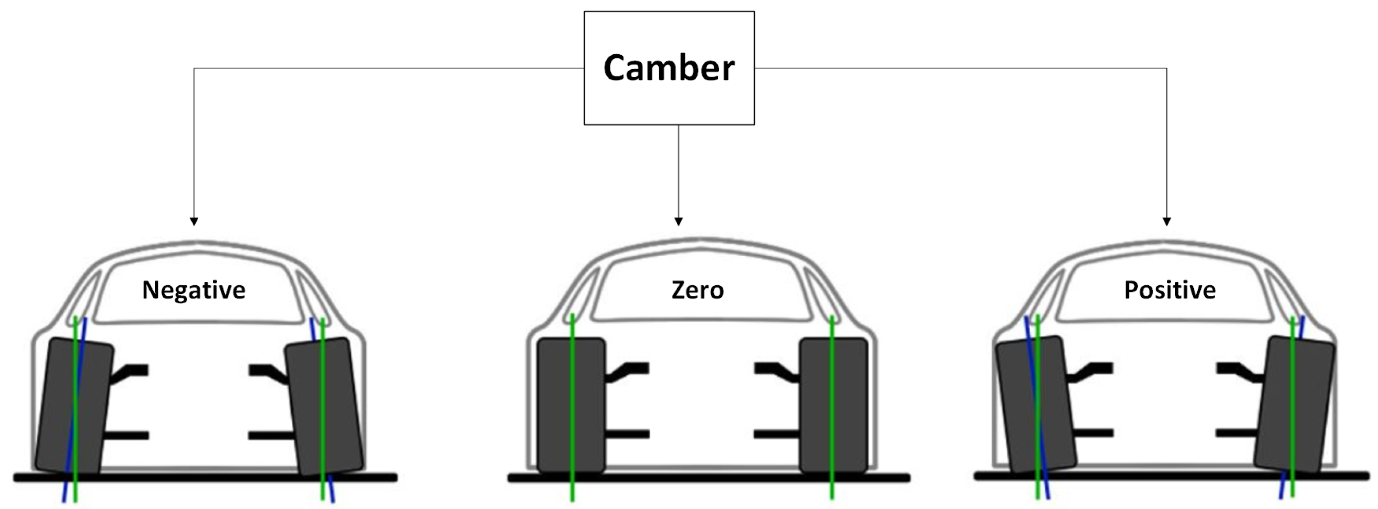
3.1. Camber
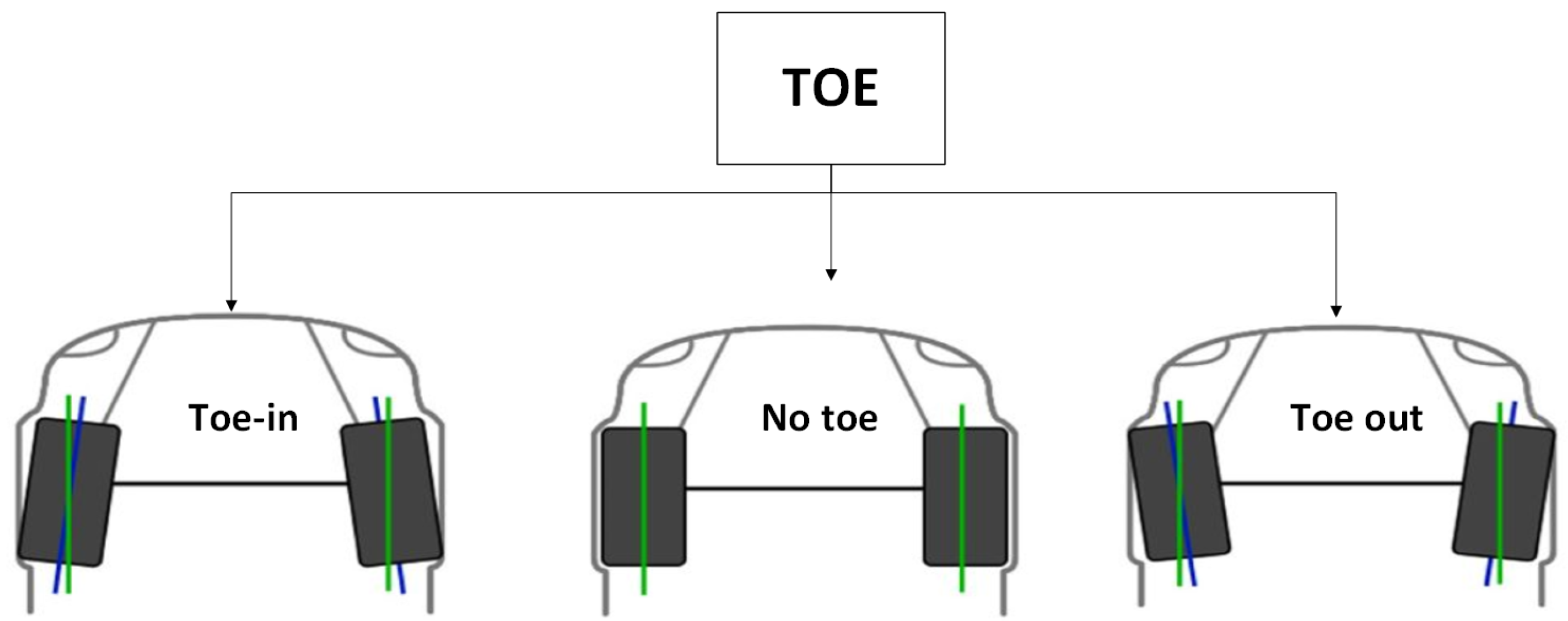
3.2. Toe
| Suspension Type | Challenges for Toe | Impact on Vehicle Performance | Proposed Solutions/Innovations | Ref |
|---|---|---|---|---|
| MacPherson | Toe variations during dynamic loading cause instability and uneven tire wear. | Decreased steering precision and safety under cornering loads. | Use of optimized suspension geometry and advanced kinematic modeling to reduce toe variations. | [59] |
| Double Wishbone | High sensitivity to manufacturing tolerances results in dynamic toe misalignment. | Increased rolling resistance and tire wear during suspension movements. | Implementation of machine learning algorithms to predict and compensate for misalignment. | [60] |
| Multi-Link | Toe changes under high-speed maneuvers due to complex linkage interactions. | Compromised high-speed stability and cornering performance. | Integration of control algorithms for active suspension systems to adjust toe dynamically. | [61] |
| Trailing Arm | Difficulty maintaining toe alignment in off-road conditions with extreme axle articulation. | Poor off-road handling and higher risks of suspension component fatigue. | Utilization of flexible bushings and enhanced suspension geometry to accommodate dynamic toe changes. | [62] |
| General Challenges | Real-time adjustment of toe under varying load conditions is complex and expensive. | Reduced energy efficiency and higher emissions due to excessive rolling resistance. | Adoption of predictive toe adjustment mechanisms using artificial neural networks and onboard sensor systems. | [63] |
3.3. Caster
| Suspension Type | Challenges for Caster | Impact on Vehicle Performance | References |
|---|---|---|---|
| MacPherson | Caster variation during dynamic loading leads to inconsistent steering returnability and high-speed instability. | Reduced high-speed stability and steering responsiveness. | [59] |
| Double Wishbone | Maintaining precise caster alignment is challenging under varying load conditions and high-speed cornering. | Increased tire wear and reduced steering efficiency. | [68] |
| Multi-Link | Complexity in suspension geometry leads to caster misalignment under high-speed braking or acceleration. | Compromised braking stability and increased lateral tire wear. | [69] |
| Trailing Arm | Difficulty maintaining consistent caster under rugged off-road conditions and extreme axle articulation. | Poor off-road handling and decreased vehicle stability. | [70] |
| General Challenge | Real-time caster adjustments require complex and costly systems, limiting widespread adoption. | Increased development costs and limited applicability for budget vehicles. | [71] |

4. Optimization Algorithms for Automotive Suspension
4.1. Artificial Intelligence Solution
4.1.1. Genetic Algorithm
| Objective | Application | Impact | References |
|---|---|---|---|
| Camber Optimization | Minimize variability in alignment | Improved handling and tire wear | [36] |
| Toe Angle Control | Maintain consistent toe alignment | Reduced lateral forces and wear | [80] |
| Caster Adjustment | Improve steering stability | Enhanced driver control | [79] |
4.1.2. Particle Swarm Optimization
- is the velocity of particle i at iteration t;
- is the position of the particle i at iteration t;
- is inertia weight;
- are the acceleration of coefficients;
- are random numbers between 0 and 1;
- is the best known position of particle i;
- is the best known position among all the particles in the swarm.
4.1.3. Gradient Descent
- : current parameter values at iteration t;
- : learning rate, a scalar that determines the step size during the gradient descent;
- : gradient of the objective function at , indicating the direction of steepest ascent.
| Objective | Application | Impact | References |
|---|---|---|---|
| Camber Angle Adjustment | Reduce dynamic variability | Improved cornering stability | [83] |
| Toe Alignment | Optimize toe during braking | Reduced tire wear | [84] |
| Caster Stability | Minimize steering variability | Enhanced handling and safety | [85] |
4.1.4. Ant Colony Optimization
- is the amount of pheromone on the edge connecting nodes i and j at time t;
- is the pheromone evaporation rate;
- represents the amount of pheromone deposited, typically depending on the quality of the solution that used edge .
4.2. Quantum Computing Solution
4.2.1. Quantum Types and Algorithms
| Ref|Detail | Optimization Objective | Application | Impact | Rationale for Quantum Method Selection |
|---|---|---|---|---|
| [92]: Discusses QAOA for query optimizations and its scalability. | Multi-objective optimization | Dynamic camber, caster, and toe tuning | Improved vehicle handling | Gate-based methods excel in achieving precise multi-objective optimization using QAOA. |
| [93]: Provides optimization methods for gate-model neural networks. | Multi-objective optimization | Optimization of suspension geometry | Enhanced stability and performance | Gate-based approaches leverage high coherence to explore complex suspension geometries efficiently. |
| [94]: Introduces enhanced algorithms for combinatorial optimization. | Combinatorial optimization | Suspension stiffness and damping tuning | Enhanced ride comfort | Variational algorithms effectively solve combinatorial challenges in suspension design. |
| [95]: Explores quantum optimization for engineering structures. | Structural optimization | Load distribution in suspension systems | Improved durability and efficiency | Gate-based methods adapt well to load distribution challenges using advanced Hamiltonian modeling. |
| [96]: Applies annealing for scheduling optimization problems. | Energy minimization | Global suspension parameter optimization | Enhanced stability and comfort | Quantum annealing maps complex constraints to energy landscapes, finding optimal solutions effectively. |
| [97]: Discusses industrial optimization using annealing. | Constraint satisfaction | Dynamic camber and caster adjustments | Enhanced vehicle maneuverability | Annealing handles real-time optimization by rapidly finding feasible solutions in dynamic scenarios. |
| [98]: Explores mission optimization with annealing and QAOA comparisons. | Combinatorial optimization | Suspension hard-point location selection | Increased design efficiency | Annealing excels in combinatorial tasks, identifying optimal configurations from numerous possibilities. |
| [99]: Evaluates gradient-based optimizations on quantum hardware. | Gradient optimization | Toe alignment tuning | Reduced tire wear | Annealing methods handle gradient-based optimization in complex, multidimensional design spaces effectively. |
Gate-Based Quantum Computing
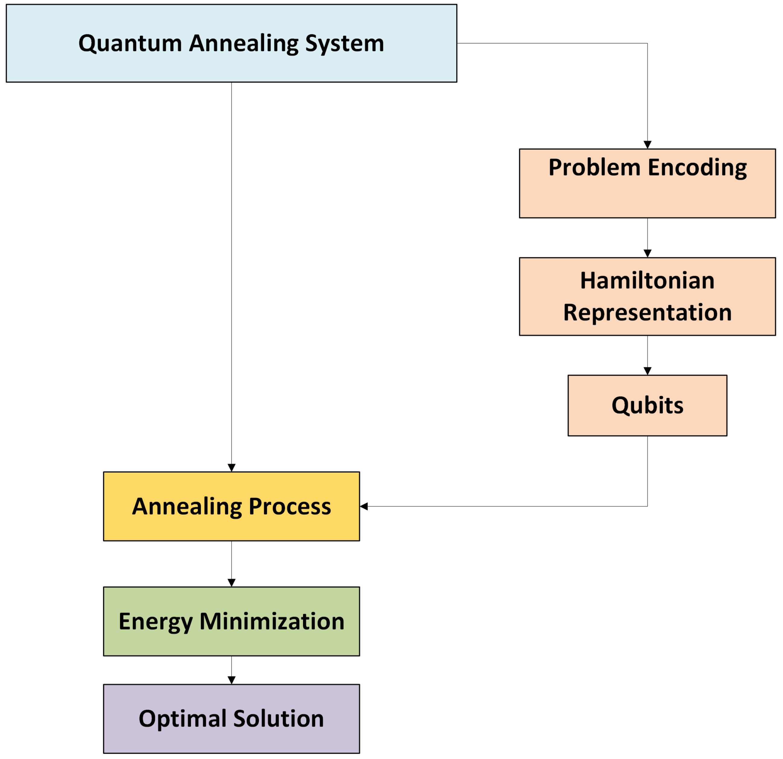
Quantum Annealing
| Application | Purpose | How It Works |
|---|---|---|
| Quantum Annealing for Optimization | Used to solve combinatorial optimization problems like the traveling salesman problem, protein folding, and resource allocation. | Steps:
|
| Quantum Machine Learning | Accelerates tasks like training neural networks and clustering data. | Steps:
|
5. Conclusions and Future Work
Author Contributions
Funding
Institutional Review Board Statement
Informed Consent Statement
Data Availability Statement
Conflicts of Interest
Abbreviations
| QAOA | Quantum Approximate Optimization Algorithm |
| PSO | Particle Swarm Optimization |
| GA | Genetic Algorithm |
| ACO | Ant Colony Optimization |
| FEA | Finite Element Analysis |
| SAVGS | Series Active Variable Geometry Suspension |
| MCDM | Multi-criteria Decision making |
| MOO | Multi-objective Optimization |
| MOPSO | Multi-Objective Particle Swarm Optimization |
References
- Ebrahimi-Nejad, S.; Kheybari, M.; Borujerd, S.V.N. Multi-objective optimization of a sports car suspension system using simplified quarter-car models. Mech. Ind. 2020, 21, 412. [Google Scholar] [CrossRef]
- Gandhi, O.; Nagar, T. Detailed Concept Selection Strategy for Rear Suspension Design Entailing Comparison Between H-Arm and Trailing-Arm Geometries for ATV Application; No. 2021-28-0245; SAE Technical Paper: Warrendale, PA, USA, 2021. [Google Scholar]
- Qin, S.; Peng, C.; Chen, Y.; He, J.; Li, P.; Chen, J. Robust kinematics design of MacPherson suspension based on a double-loop multi-objective particle swarm optimization algorithm. Proc. Inst. Mech. Eng. Part D J. Automob. Eng. 2019, 233, 3263–3278. [Google Scholar] [CrossRef]
- Karande, S.R.; Chinnapandi, L.B.M.; Jeyaraj, P.; Subramanian, J. Kinematics and compliance analysis of active suspension system and Development of control algorithm to maximize ride comfort. IOP Conf. Ser. Mater. Sci. Eng. 2021, 1128, 012044. [Google Scholar] [CrossRef]
- Xue, H.; Gobbi, M.; Matta, A. Multi-fidelity surrogate-based optimal design of road vehicle suspension systems. Optim. Eng. 2023, 24, 2773–2794. [Google Scholar] [CrossRef]
- Liu, J. Optimal Design and Analysis of Intelligent Vehicle Suspension System Based on ADAMS and Artificial Intelligence Algorithms. J. Phys. Conf. Ser. 2021, 2074, 012023. [Google Scholar] [CrossRef]
- Team, BMW Group Quantum; Klepsch, J.; Finžgar, J.R.; Kiwit, F.; Hölscher, L.; Erdmann, M.; Müller, L.; Kumar, C.; Luckow, A. Quantum Computing for Automotive Applications: From Algorithms to Applications. arXiv 2024, arXiv:2409.14183. [Google Scholar] [CrossRef]
- Al-Zughaibi, A. Automotive Suspension System Modelling and Controlling. Ph.D. Thesis, Cardiff University, Cardiff, UK, 2019. [Google Scholar]
- Wu, Q.; Liu, F.; Yin, H.; Huang, J. Constraint-Based Adaptive Robust Control for Active Suspension Systems Under the Sky-Hook Model. IEEE Trans. Ind. Electron. 2021, 69, 5152–5164. [Google Scholar] [CrossRef]
- Yaghoubi, S.; Ghanbarzadeh, A. Modeling and optimization of car suspension system in the presence of magnetorheological damper using Simulink-PSO hybrid technique. Results Eng. 2024, 22, 102065. [Google Scholar] [CrossRef]
- Zhu, S.; He, Y. A Design Synthesis Method for Robust Controllers of Active Vehicle Suspensions. Designs 2022, 6, 14. [Google Scholar] [CrossRef]
- Page, M.J.; Joanne, E.M.; Bossuyt, P.M.; Boutron, I.; Hoffmann, T.C.; Mulrow, C.D.; Shamseer, L.; Tetzlaff, J.M.; Akl, E.A.; Brennan, S.E.; et al. The PRISMA 2020 Statement: An Updated Guideline for Reporting Systematic Reviews. BMJ 2021, 372, n71. [Google Scholar] [CrossRef]
- Grotti, E.; Mizushima, D.M.; Backes, A.D.; de Freitas Awruch, M.D.; Gomes, H.M. A novel multi-objective quantum particle swarm algorithm for suspension optimization. Comput. Appl. Math. 2020, 39, 1–29. [Google Scholar] [CrossRef]
- Wang, Z.; Liu, C.; Zheng, X.; Zhao, L.; Qiu, Y. Advancements in Semi-Active Automotive Suspension Systems with Magnetorheological Dampers: A Review. Appl. Sci. 2024, 14, 7866. [Google Scholar] [CrossRef]
- Sonko, S.; Daudu, C.D.; Osasona, F.; Monebi, A.M.; Etukudoh, E.A.; Atadoga, A. The evolution of embedded systems in automotive industry: A global review. World J. Adv. Res. Rev. 2024, 21, 96–104. [Google Scholar] [CrossRef]
- David, M.; Arzola, N.; Araque, O. Optimal design of leaf springs for vehicle suspensions under cyclic conditions. Ingeniare Rev. Chil. Ing. 2022, 30, 23–36. [Google Scholar] [CrossRef]
- Joshi, N.Y.; Prajapati, H.; Patel, A.J.; Chaudhari, S.N. Design and Analysis of Suspension System for Light Weight Vehicle. Int. J. Adv. Res. Ind. Inf. Eng. 2020, 6, 1428–1437. [Google Scholar]
- Viadero-Monasterio, F.; Boada, B.L.; Zhang, H.; Boada, M.J.L. Integral-based event triggering actuator fault-tolerant control for an active suspension system under a networked communication scheme. IEEE Trans. Veh. Technol. 2023, 72, 13848–13860. [Google Scholar] [CrossRef]
- Viadero-Monasterio, F.; Meléndez-Useros, M.; Jiménez-Salas, M.; Boada, B.L. Robust Static Output Feedback Control of a Semi-Active Vehicle Suspension Based on Magnetorheological Dampers. Appl. Sci. 2024, 14, 10336. [Google Scholar] [CrossRef]
- Mishra, S.; Prasad, T.; Sanz, J.M. Adopting Pothole Mitigation System for Improved Ride, Handling and Enhanced Component Life; No. 2024-26-0059; SAE Technical Paper: Warrendale, PA, USA, 2024. [Google Scholar]
- Chen, Q.; Bai, X.X.F.; Zhu, A.D.; Wu, D.; Deng, X.C.; Li, Z.D. Influence of balanced suspension on handling stability and ride comfort of off-road vehicle. Proc. Inst. Mech. Eng. Part D J. Automob. Eng. 2021, 235, 1602–1616. [Google Scholar] [CrossRef]
- Ning, D.; Du, H.; Zhang, N.; Sun, S.; Li, W. Controllable Electrically Interconnected Suspension System for Improving Vehicle Vibration Performance. IEEE/ASME Trans. Mechatronics 2020, 25, 859–871. [Google Scholar] [CrossRef]
- Liberman, Y.L.; Lepihin, E.V.; Gorbunova, L.N. New Design of Spring-Hydraulic Suspension for Vehicle Wheels. Handbook. Eng. J. Suppl. 2024, 2, 25–28. [Google Scholar]
- Ghanshyam, S.; Singh, M.; Chopra, N. Design, Analysis, and Comparative Study of Conventional Double Wishbone Control Arms with Modified Split Type Control Arms Design for a Passenger Car; SAE Technical Paper: Warrendale, PA, USA, 2024. [Google Scholar] [CrossRef]
- Dehbari, S.; Marzbanrad, J. Kinematic and Dynamic Analysis for a New MacPherson Strut Suspension System. Mech. Mech. Eng. 2018, 22, 223–1238. [Google Scholar] [CrossRef]
- Su, Z.; Xu, F.; Hua, L.; Chen, H.; Wu, K.; Zhang, S. Design optimization of minivan MacPherson-strut suspension system based on weighting combination method and neighborhood cultivation genetic algorithm. Proc. Inst. Mech. Eng. Part D J. Automob. Eng. 2018, 233, 650–660. [Google Scholar] [CrossRef]
- Gao, J.; Wu, F. Analysis and optimization of the vehicle handling stability with considering suspension kinematics and compliance characteristics. Adv. Mech. Eng. 2021, 13, 16878140211015523. [Google Scholar] [CrossRef]
- OptimumG, LLC. OptimumKinematics 2.0.2 (Build 0401); OptimumG: Denver, CO, USA, 2011; Available online: https://www.optimumg.com (accessed on 24 December 2024).
- Inzamam, H.; Jani, H.; Rasal, S.; Asthana, S.; Ahire, M.; Jadhav, P.; Lenka, V.; Vellandi, V. SUV Multi-Link Rigid Axle Control Links Optimization for Ride and Handling Improvement; No. 2024-26-0048; SAE Technical Paper: Warrendale, PA, USA, 2024. [Google Scholar] [CrossRef]
- Harshil, J.; Rasal, S.; Hussain, I.; Asthana, S.; Ahire, M.; Vellandi, V.; Senniappan, M. Experimental Analysis of Multi-Link Rigid Axle Suspension Camber Variation with Vehicle Load; No. 2024-26-0054; SAE Technical Paper: Warrendale, PA, USA, 2024. [Google Scholar] [CrossRef]
- Shingade, M.; Pable, M.; Pawar, A. Design and Development: A Simulation Approach of Multi-Link Front Suspension for an All-Terrain Vehicle; No. 2021-26-0077; SAE Technical Paper: Warrendale, PA, USA, 2021. [Google Scholar]
- Choi, B.C.; Cho, S.; Kim, C.W. Kriging Model Based Optimization of MacPherson Strut Suspension for Minimizing Side Load using Flexible Multi-Body Dynamics. Int. J. Precis. Eng. Manuf. 2018, 19, 873–879. [Google Scholar] [CrossRef]
- Lee, L.-W.; Chiang, H.-H.; Li, I.-H. Performance Improvement of Active MacPherson Suspension Using a Pneumatic Muscle and an Intelligent Vibration Compensator. IEEE Access 2020, 8, 34080–34095. [Google Scholar] [CrossRef]
- Taneva, S.; Ambarev, K. Comparison of natural frequencies of a macpherson suspension arm using different bushings. Environment. Technologies. Resources. In Proceedings of the International Scientific and Practical Conference, Rezekne, Latvia, 27–28 June 2024; Volume 1, pp. 348–351. [Google Scholar] [CrossRef]
- Singh, A.; Pawar, S.; Soundalkar, M.; Ali, M.A. Design Optimization of the Control Arms of a Double Wishbone Suspension System Using Topological Approach. Int. J. Sci. Res. Eng. Manag. (IJSREM) 2024, 8. Available online: https://ijsrem.com/download/design-optimization-of-the-control-arms-of-a-double-wishbone-suspension-system-using-topological-approach/ (accessed on 24 December 2024). [CrossRef]
- Arshad, M.W.; Lodi, S. Optimization of Double Wishbone Suspension: Evaluating the Performance of Classes of Algorithms. In Proceedings of the 2024 International Conference on Applied Mathematics & Computer Science (ICAMCS), Venice, Italy, 28–30 September 2024; pp. 156–161. [Google Scholar]
- Kavitha, C.; Shankar, S.A.; Karthika, K.; Ashok, B.; Ashok, S.D. Active camber and toe control strategy for the double wishbone suspension system. J. King Saud Univ.-Eng. Sci. 2019, 31, 375–384. [Google Scholar] [CrossRef]
- Tang, C.; He, L.; Khajepour, A. Design and analysis of an integrated suspension tilting mechanism for narrow urban vehicles. Mech. Mach. Theory 2018, 120, 225–238. [Google Scholar] [CrossRef]
- Borase, P.D.; Babele, V.; Khare, G. FEA-Based Analysis of Front Control Lower Arm in Automotive Suspension. Int. J. Sci. Res. Eng. Manag. 2024, 8, 1–6. [Google Scholar] [CrossRef]
- Hiremath, I.; Nalawade, A.; Patil, J.; Patil, S.; Patil, R.; Ugalmugale, S. Design and Development of Semi Trailing Arm Suspension System for an Off-Road Vehicle. Int. J. Res. Eng. Sci. Manag. 2020, 3, 339–342. [Google Scholar]
- Demli, U.Ö.; Acar, E. Design optimization of armored wheeled vehicle suspension lower control arm. Mater. Test. 2022, 64, 932–944. [Google Scholar] [CrossRef]
- Kline, D.; Hulbert, G. Set-Based Design of Automobile Independent Suspension Linkages. In Proceedings of the 5th Joint International Conference on Multibody System Dynamics, Lisboa, Portugal, 24–28 June; pp. 1–17.
- Németh, B.; Fényes, D.; Gáspár, P.; Bokor, J. Coordination of Independent Steering and Torque Vectoring in a Variable-Geometry Suspension System. IEEE Trans. Control Syst. Technol. 2019, 27, 2209–2220. [Google Scholar] [CrossRef]
- Yıldız, B.S.; Yıldız, A.R.; Albak, E.İ.; Abderazek, H.; Sait, S.M.; Bureerat, S. Butterfly optimization algorithm for optimum shape design of automobile suspension components. Mater. Test. 2020, 62, 365–370. [Google Scholar] [CrossRef]
- Yu, M.; Cheng, C.; Evangelou, S.A.; Dini, D. Series Active Variable Geometry Suspension: Full-Car Prototyping and Road Testing. IEEE/ASME Trans. Mechatron. 2022, 27, 1332–1344. [Google Scholar] [CrossRef]
- Ataei, M.; Tang, C.; Khajepour, A.; Jeon, S. Active camber system for lateral stability improvement of urban vehicles. Proc. Inst. Mech. Eng. Part D J. Automob. Eng. 2019, 233, 3824–3838. [Google Scholar] [CrossRef]
- Djap, S.; Ku, P.X. Impact of camber angle on the tire tread behaviour in different road conditions. J. Phys. Conf. Ser. 2023, 2523, 012041. [Google Scholar] [CrossRef]
- El-Zomor, H.M.; Mohamed, E.S. Vehicle Motion Stability Enhancement Based on Active Camber Angle Control for a Double Wishbone Suspension. Int. J. Veh. Struct. Syst. 2020, 12, 134. [Google Scholar] [CrossRef]
- Tzortzis, I.N.; Papalamprou, G.; Katzourakis, D. Introducing a Yaw Rate-Based Control System for Adjusting the Camber Angle of the Front Wheels on a Prototype Vehicle. In Proceedings of the 2024 32nd Mediterranean Conference on Control and Automation (MED), Crete, Greece, 11–14 June 2024; pp. 340–345. [Google Scholar] [CrossRef]
- Kwietniewski, M.; Bil, T. Analysis of the non-wishbone mechanism in a vehicle wheel suspension. J. Theor. Appl. Mech. 2020, 58, 109–115. [Google Scholar] [CrossRef]
- Zhang, S.; Gao, Y.; Gao, D.; Pan, T.; Yang, J. Serial combinational optimization method for double wishbone suspension’s pseudo damage improvement. Struct. Multidiscip. Optim. 2023, 66, 122. [Google Scholar] [CrossRef]
- Parida, P.; Itkikar, V.; Patil, H.; Patil, S. Design and Development of Multi - Link Suspension System. Int. J. Sci. Dev. Res. (IJSDR) 2019, 4, 120–124. [Google Scholar]
- Nikam, S.; Morankar, V.; Kakatkar, K.; Mali, R.; Nimgade, M. Optimisation of Camber Angle for Better Ride Comfort and Vehicle Handling using ADAMS CAR. J. Emerg. Technol. Innov. Res. 2019, 6, 401–404. [Google Scholar]
- Zhang, X.; Wang, L.; Guo, K.; Yao, Q.; Feng, Q.; Yi, Z. Control-Configured Design on Controllable Suspensions: Active Camber as a Case Study. In The IAVSD International Symposium on Dynamics of Vehicles on Roads and Tracks; Springer Nature: Cham, Switzerland, 2023; pp. 165–175. [Google Scholar] [CrossRef]
- Das, R.K.; Hossain, M.A.M.; Islam, M.T.; Banik, S.C.; Hafez, M.G. Effects of Front Total Toe-In Angle on Tire Wear and Emissions for a Light-Duty Vehicle. J. Eng. 2024, 2024, 5723254. [Google Scholar] [CrossRef]
- An, X. Analysis of the impact of vehicle toe-in angle on vehicle stability. In Proceedings of the International Symposium on Robotics, Artificial Intelligence, and Information Engineering (RAIIE 2022), Hohhot, China, 15–17 July 2022. [Google Scholar] [CrossRef]
- Lee, H.; Choi, S.B. Online Detection of Toe Angle Misalignment Based on Lateral Tire Force and Tire Aligning Moment. Int. J. Automot. Technol. 2023, 24, 623–632. [Google Scholar] [CrossRef]
- Wei, D.; Zhu, Y.; Shi, W.; Wang, Y.; Zhang, B.; Yin, A. A new design to match the vehicle toe-in and camber considering the cornering property of the tire. J. Adv. Mech. Des. Syst. Manuf. 2020, 14, JAMDSM0004. [Google Scholar] [CrossRef]
- Chen, Q.; Kang, S.; Li, X.; Wu, M.; Wei, J.; Liu, Y. Research on modeling and optimization simulation analysis of micro electric vehicle suspension. J. Vibroeng. 2020, 22, 923–932. [Google Scholar] [CrossRef]
- Garg, S.; Dudeja, S.; Gupta, S.; Rastogi, V. Optimization of a Double Wishbone Suspension Geometry for Off-road Vehicles using Genetic Algorithm and Machine Learning. In Proceedings of the 2022 13th International Conference on Mechanical and Aerospace Engineering (ICMAE), Bratislava, Slovakia, 20–22 July 2022; pp. 472–477. [Google Scholar] [CrossRef]
- Chen, X.; Xu, N.; Guo, K. Tire wear estimation based on nonlinear lateral dynamic of multi-axle steering vehicle. Int. J. Automot. Technol. 2018, 19, 63–75. [Google Scholar] [CrossRef]
- Baghel, S.G. Rear Wheel Roll Steering (Passive) Suspension Mechanism. ARAI J. Mobil. Technol. 2022, 2, 112–124. [Google Scholar] [CrossRef]
- Belkhode, P.N. Analysis and Interpretation of Steering Geometry of Automobile Using Artificial Neural Network Simulation. Engineering 2019, 11, 231. [Google Scholar] [CrossRef]
- Wan, H. Caster Angle and Directional Stability of a Car Application to Sports Car. Highlights Sci. Eng. Technol. 2022, 13, 21–29. [Google Scholar] [CrossRef]
- Wang, Z. Methods in Research about Effect of Caster Angle on Vehicle Steering and Stability. Highlights Sci. Eng. Technol. 2022, 13, 45–53. [Google Scholar] [CrossRef]
- He, H. The Relationship Between Car Caster Angle and the Directional Stability of Car. Highlights Sci. Eng. Technol. 2022, 13, 1–6. [Google Scholar] [CrossRef]
- Vo, D.Q. Variable caster steering in vehicle dynamics. Proc. Inst. Mech. Eng. Part D J. Automob. Eng. 2018, 232, 1270–1284. [Google Scholar] [CrossRef]
- Upadhyay, P.; Deep, M.; Dwivedi, A.; Agarwal, A.; Bansal, P.; Sharma, P. Design and analysis of double wishbone suspension system. IOP Conf. Ser. Mater. Sci. Eng. 2020, 748, 012020. [Google Scholar] [CrossRef]
- Schwartz, M.; Goosmann, T.; Hohmann, S. Kinematic Sensitivity Analysis of the Suspension Characteristics for the Initial Design of Four-Wheel Drive and Four-Wheel Steered Vehicles; No. 2020-01-0990; SAE Technical Paper: Warrendale, PA, USA, 2020. [Google Scholar] [CrossRef]
- Yang, C.; Xu, N.; Wang, W.; Li, W.; Ren, Z. Self-steering performance of a new bogie with four independently rotating wheels using caster angle. Int. J. Rail Transp. 2023, 12, 476–491. [Google Scholar] [CrossRef]
- Sakai, H. Revealing the Impact of Motorcycle Caster Angles on Weave and Wobble: A Comprehensive Analysis Through Visualized Stability Testing; No. 2024-01-2770; SAE Technical Paper: Warrendale, PA, USA, 2024. [Google Scholar] [CrossRef]
- Fossati, G.G.; Miguel, L.F.F.; Casas, W.J.P. Multi-objective optimization of the suspension system parameters of a full vehicle model. Optim. Eng. 2018, 20, 151–177. [Google Scholar] [CrossRef]
- Zhao, Q.; Zhu, B. Multi-objective optimization of active suspension predictive control based on improved PSO algorithm. J. Vibroeng. 2019, 21, 1388–1404. [Google Scholar] [CrossRef]
- Bingül, Ö.; Yıldız, A. Fuzzy logic and proportional integral derivative based multi-objective optimization of active suspension system of a 4 × 4 in-wheel motor driven electrical vehicle. J. Vib. Control 2023, 29, 1366–1386. [Google Scholar] [CrossRef]
- Song, C.Y.; Choi, H.Y.; Byon, S.K. Meta-model Effects on Approximate Multi-objective Design Optimization of Vehicle Suspension Components. Korean Soc. Manuf. Process. Eng. 2019, 18, 74–81. [Google Scholar] [CrossRef]
- Khan, M.A.; Sardahi, Y.; Hernández Castellanos, C.I. Multi-Objective and Robust Design of a Semi-Active Suspension System. Int. J. Eng. Sci. Technol. 2022, 4, 1–13. [Google Scholar] [CrossRef]
- Sun, G.; Zhang, H.; Fang, J.; Li, G.; Li, Q. A new multi-objective discrete robust optimization algorithm for engineering design. Appl. Math. Model. 2018, 53, 602–621. [Google Scholar] [CrossRef]
- Park, H.; Langari, R.; Yi, H. Design and testing of double-wishbone suspension for enhanced outdoor maneuver stability of a six-wheeled mobile robot. Mechatronics 2024, 103, 103237. [Google Scholar] [CrossRef]
- Papaioannou, G.; Koulocheris, D. Multi-objective optimization of semi-active suspensions using KEMOGA algorithm. Eng. Sci. Technol. Int. J. 2019, 22, 1035–1046. [Google Scholar] [CrossRef]
- Shojaeefard, M.H.; Khalkhali, A.; Faghihian, H.; Dahmardeh, M. Optimal platform design using non-dominated sorting genetic algorithm II and technique for order of preference by similarity to ideal solution; application to automotive suspension system. Eng. Optim. 2018, 50, 471–482. [Google Scholar] [CrossRef]
- Ma, X.; Wong, P.K.; Zhao, J. Practical multi-objective control for automotive semi-active suspension system with nonlinear hydraulic adjustable damper. Mech. Syst. Signal Process. 2019, 117, 667–688. [Google Scholar] [CrossRef]
- Qazi, A.J.; Farooqui, U.A.; Khan, A.; Khan, M.T.; Mazhar, F.; Fiaz, A. Optimization of semi-active suspension system using particle swarm optimization algorithm. Aasri Procedia 2013, 4, 160–166. [Google Scholar] [CrossRef]
- Yang, Z.; Yong, C.; Li, Z.; Kangsheng, Y. Simulation analysis and optimization of ride quality of in-wheel motor electric vehicle. Adv. Mech. Eng. 2018, 10, 1687814018776543. [Google Scholar] [CrossRef]
- Lu, A.; Li, R.; Yu, Y.; Ji, W.; Hou, Y.; Tian, G. Impacts of Dynamic Toe Angle Variations on Four-Wheel Independent Steering Control and their Optimization Strategies; No. 2024-01-2321; SAE Technical Paper: Warrendale, PA, USA, 2024. [Google Scholar] [CrossRef]
- Balzer, L.; Mees, V.; Millitzer, J.; Lapiccirella, G. Simulation-Based Multi-Objective Optimization of a Fuzzy Controller for Semi-Active Suspension; Universitätsbibliothek der RWTH Aachen: Aachen, Germany, 2019. [Google Scholar]
- Bahrami Joo, B.; Jamali, A.; Nariman-zadeh, N. Multi-objective robust design approach usage in integration of bond graph and genetic programming. Int. J. Model. Simul. 2021, 42, 743–759. [Google Scholar] [CrossRef]
- Xiong, F.; Wang, D.; Chen, S.; Gao, Q.; Tian, S. Multi-objective lightweight and crashworthiness optimization for the side structure of an automobile body. Struct. Multidiscip. Optim. 2018, 58, 1823–1843. [Google Scholar] [CrossRef]
- Fankhauser, T.; Solèr, M.E.; Füchslin, R.M.; Stockinger, K. Multiple Query Optimization using a Hybrid Approach of Classical and Quantum Computing. arXiv 2021, arXiv:2107.10508. [Google Scholar]
- Cheng, L.; Chen, Y.-Q.; Zhang, S.-X.; Zhang, S. Quantum approximate optimization via learning-based adaptive optimization. Commun. Phys. 2023, 7, 83. [Google Scholar] [CrossRef]
- Frisk Kockum, A.; Fitzek, D.; Granath, M.; Ghandriz, T.; Laine, L. Applying quantum approximate optimization to the heterogeneous vehicle routing problem. Aps March Meet. Abstr. 2022, 2022, G36-011. [Google Scholar]
- Ajagekar, A.; You, F. Quantum computing for energy systems optimization: Challenges and opportunities. Energy 2019, 179, 76–89. [Google Scholar] [CrossRef]
- Fankhauser, T.; Solèr, M.E.; Füchslin, R.M.; Stockinger, K. Multiple query optimization using a gate-based quantum computer. IEEE Access 2023, 11, 114031–114043. [Google Scholar] [CrossRef]
- Gyongyosi, L.; Imre, S. Training optimization for gate-model quantum neural networks. Sci. Rep. 2019, 9, 12679. [Google Scholar] [CrossRef] [PubMed]
- Amaro, D.; Modica, C.; Rosenkranz, M.; Fiorentini, M.; Benedetti, M.; Lubasch, M. Filtering variational quantum algorithms for combinatorial optimization. Quantum Sci. Technol. 2022, 7, 015021. [Google Scholar] [CrossRef]
- Xu, Y.; Wang, X.; Wang, Z. Gate-Based Variational Quantum Algorithm for Truss Structure Size Optimization Problem. AIAA J. 2024, 62, 4824–4833. [Google Scholar] [CrossRef]
- Mohammadbagherpoor, H.; Dreher, P.; Ibrahim, M.; Oh, Y.H.; Hall, J.; Stone, R.E.; Stojkovic, M. Exploring airline gate-scheduling optimization using quantum computers. arXiv 2021, arXiv:2111.09472. [Google Scholar]
- Sturm, A.; Mummaneni, B.; Rullkötter, L.; Mummaneni, B.; Rullkötter, L. Unlocking Quantum Optimization: A Use Case Study on NISQ Systems. arXiv 2024, arXiv:2404.07171. [Google Scholar]
- Cutugno, M.; Giani, A.; Alsing, P.M.; Wessing, L.; Schnore, A. Quantum computing approaches for mission covering optimization. Algorithms 2022, 15, 224. [Google Scholar] [CrossRef]
- Schuld, M.; Bergholm, V.; Gogolin, C.; Izaac, J.; Killoran, N. Evaluating analytic gradients on quantum hardware. Phys. Rev. A 2019, 99, 032331. [Google Scholar] [CrossRef]
- Khairy, S.; Shaydulin, R.; Cincio, L.; Alexeev, Y.; Balaprakash, P. Learning to Optimize Variational Quantum Circuits to Solve Combinatorial Problems. In Proceedings of the AAAI Conference on Artificial Intelligence, New York, NY, USA, 7–8 February 2020; pp. 2367–2375. [Google Scholar] [CrossRef]
- Perez-Ramirez, D.F. Variational quantum algorithms for combinatorial optimization. arXiv 2024, arXiv:2407.06421. [Google Scholar]
- Biamonte, J. Universal Variational Quantum Computation. Phys. Rev. 2021, 103, L030401. [Google Scholar] [CrossRef]
- Greenaway, S.; Petiziol, F.; Zhao, H.; Mintert, F. Variational Quantum Gate Optimization at the Pulse Level. Scipost Phys. 2024, 16, 082. [Google Scholar] [CrossRef]
- Gabor, T.; Rosenfeld, M.L.; Linnhoff-Popien, C.; Feld, S. How to approximate any objective function via quadratic unconstrained binary optimization. In Proceedings of the 2022 IEEE International Conference on Software Analysis, Evolution and Reengineering (SANER), Honolulu, HI, USA, 15–18 March 2022; pp. 1249–1257. [Google Scholar]
- Mehta, A.; Muradi, M.; Woldetsadick, S. Quantum annealing based optimization of robotic movement in manufacturing. In Proceedings of the Quantum Technology and Optimization Problems: First International Workshop, QTOP 2019, Munich, Germany, 18 March 2019; Proceedings 1. Springer International Publishing: Berlin/Heidelberg, Germany, 2019; pp. 136–144. [Google Scholar]


| Feature | Passive Suspension | Semi-Active Suspension | Active Suspension |
|---|---|---|---|
| Adaptability | Fixed | Adjustable damping | Fully adaptive in real time |
| Complexity | Low | Moderate | High |
| Cost | Low | Moderate | High |
| Energy Consumption | None | Low | High |
| Ride Comfort | Basic | Improved | Excellent |
| Handling Performance | Limited | Enhanced | Superior |
| Maintenance Needs | Low | Moderate | High |
| Suspension Type | Challenges for Camber | Impact on Vehicle Performance | Proposed Solutions/Innovations |
|---|---|---|---|
| MacPherson [50] | Camber variation during suspension compression/extension, affecting stability and safety. | Reduced handling precision and tire contact patch, especially during dynamic maneuvers. | Incorporation of camber control actuators and improved suspension geometry design. |
| Double Wishbone [51] | Complex geometry increases design cost; maintaining optimal camber under varying loads is challenging. | High manufacturing and maintenance costs; inconsistent tire wear. | Adaptive camber systems using active actuators and simulation-based optimization for load handling. |
| Multi-Link [52] | High structural deflection under heavy loads causes camber angle variation and reduced handling performance. | Instability under high loads; uneven tire wear and reduced safety. | Structural reinforcement, use of lightweight high-strength materials, and load-adaptive suspension tuning. |
| Trailing Arm [53] | Limited flexibility in camber adjustments, especially for off-road conditions with high axle articulation. | Poor off-road handling and reduced vehicle stability in rough terrain. | Integration of flexible trailing arms and real-time suspension geometry adjustment mechanisms. |
| General Challenges [54] | Achieving an adaptive system to maintain camber under dynamic conditions without compromising cost and simplicity. | Limited applicability for high-performance or cost-sensitive vehicle segments. | Development of cost-effective active camber systems and advancements in simulation for suspension geometry design. |
| Objective | Application | Impact | References |
|---|---|---|---|
| Camber Optimization | Minimize response time | Enhanced vehicle responsiveness | [81] |
| Toe Angle Optimization | Reduce dynamic toe changes | Improved straight-line stability | [82] |
| Caster Optimization | Maintain consistent steering effort | Better maneuverability | [3] |
| Objective | Application | Impact | References |
|---|---|---|---|
| Camber Control | Ensure uniform tire–road contact | Improved vehicle stability | [86] |
| Toe Angle Optimization | Maintain consistent alignment | Reduced rolling resistance | [87] |
| Caster Angle Stability | Adaptive handling for dynamic loads | Increased driver control and comfort | [3] |
| Aspect | Classical Computing | Quantum Computing |
|---|---|---|
| Bit vs. Qubit | A bit is represented as a binary value: | A qubit exists in a superposition: |
| Gates and Operations | Uses Boolean logic gates (e.g., AND, OR, NOT) | Uses quantum gates that operate with unitary matrices (e.g., Hadamard, CNOT) |
| Computational Power | Solves problems sequentially; for example, factoring a number N requires exponential time: | Can solve certain problems exponentially faster [89,90]; for example, Shor’s algorithm factors N in polynomial time: |
| Principle | Description |
|---|---|
| Superposition | A qubit is a superposition of basis states and , represented as:
|
| Entanglement | Qubits can be entangled such that the state of one (no matter the distance) directly correlates with the state of another. A Bell state example is:
|
| Quantum Interference | Interference results from the superposition of states, affecting measurement outcomes:
|
| Quantum Gates | Quantum gates manipulate qubit states through superposition and entanglement. Key gates include:
|
| Algorithm | Purpose | How It Works |
|---|---|---|
| Shor’s | Designed to factorize large integers exponentially faster than classical algorithms, impacting cryptography. | Steps:
|
| Grover’s | Provides a quadratic speedup for unstructured search problems, optimizing the search in steps. | Steps:
|
Disclaimer/Publisher’s Note: The statements, opinions and data contained in all publications are solely those of the individual author(s) and contributor(s) and not of MDPI and/or the editor(s). MDPI and/or the editor(s) disclaim responsibility for any injury to people or property resulting from any ideas, methods, instructions or products referred to in the content. |
© 2025 by the authors. Licensee MDPI, Basel, Switzerland. This article is an open access article distributed under the terms and conditions of the Creative Commons Attribution (CC BY) license (https://creativecommons.org/licenses/by/4.0/).
Share and Cite
Arshad, M.W.; Lodi, S.; Liu, D.Q. Multi-Objective Optimization of Independent Automotive Suspension by AI and Quantum Approaches: A Systematic Review. Machines 2025, 13, 204. https://doi.org/10.3390/machines13030204
Arshad MW, Lodi S, Liu DQ. Multi-Objective Optimization of Independent Automotive Suspension by AI and Quantum Approaches: A Systematic Review. Machines. 2025; 13(3):204. https://doi.org/10.3390/machines13030204
Chicago/Turabian StyleArshad, Muhammad Waqas, Stefano Lodi, and David Q. Liu. 2025. "Multi-Objective Optimization of Independent Automotive Suspension by AI and Quantum Approaches: A Systematic Review" Machines 13, no. 3: 204. https://doi.org/10.3390/machines13030204
APA StyleArshad, M. W., Lodi, S., & Liu, D. Q. (2025). Multi-Objective Optimization of Independent Automotive Suspension by AI and Quantum Approaches: A Systematic Review. Machines, 13(3), 204. https://doi.org/10.3390/machines13030204