Article

Predicting the Fatigue Life of a Commercial Vehicle X-EPS Steering Gear with a Rigid–Flexible Coupling Dynamics Method

1
Zhejiang VIE Science & Technology Co., Ltd., Shaoxing 311835, China
2
College of Mechanical Engineering, Donghua University, Shanghai 201620, China
3
State Key Laboratory of Mechanical System and Vibration, Shanghai Jiao Tong University, Shanghai 200240, China
*
Author to whom correspondence should be addressed.
Machines 2025, 13(3), 218; https://doi.org/10.3390/machines13030218
Submission received: 12 February 2025 / Revised: 1 March 2025 / Accepted: 6 March 2025 / Published: 7 March 2025
(This article belongs to the Section Vehicle Engineering)

Abstract

:
Commercial X-EPS steering gears are characterized by high torque output, torque—with increasing capabilities, high reliability, and excellent handling precision. Among them, the screw–nut pair in the steering gear is subjected to complex working loads, and its raceways are prone to fatigue failure. To more accurately and effectively predict the fatigue life of the screw–nut pair in the steering gear, a method for dynamic simulation and fatigue life prediction of commercial X-EPS steering gears is proposed based on virtual prototyping technology and finite element theory. That is, a rigid–flexible coupling dynamic model of the X-EPS steering gear is established to obtain the load spectra of the screw and nut, and a finite-element static model is also established. Then, combined with the material S-N curve, the fatigue life is predicted through the NOCDE fatigue “five-block diagram”. The research results show that the screw and nut raceways are the key components prone to fatigue failure in the steering gear. The minimum numbers of fatigue life cycles are 1.028 × 10⁵ times and 2.9695 × 10⁵ times, respectively. Subsequently, a fatigue life bench test was conducted for verification. The results show that the error between the fatigue life analysis model of the XEPS recirculating ball steering gear and the test is less than 5%, meeting the requirements of the fatigue life test standard and design standard.

1. Introduction

The automobile steering gear is an important steering system component widely used in modern automobiles, and its performance is directly related to the handling stability and safety of the vehicle. According to a worldwide survey, the circulating ball steering gear accounts for about 45% [1]. In practical use, especially under extreme working conditions, the screw and nut parts of the circulating ball steering gear often experience a large load. This may lead to fatigue, which in turn affects the reliability and life of the system.
In recent years, there has been little research and analysis on the XEPS circulating ball steering gear. Hu [2], Wei [3], and other scholars studied the control strategy of the rocker shaft-type electric power steering system, transformed the dynamic differential equation of the rocker shaft-assisted EPS system into the state space equation, and applied the modern control theory. Ma [4] and others built the parametric model of the steering gear through AMESIM 2020 software to study the influence factor analysis of the assisted characteristic curve. Li [5] statically analyzed the rack–tooth fan pair according to the working characteristics of the two-stage transmission pair of the circulating ball power steering gear. Bertolino [6] used ADAMS 2021 software to evaluate the dynamic performance of the steering gear. Yue [7] examined the fatigue life of the circulating ball steering gear by using the explicit finite element software LS-DYNA 2014 to analyze the coordinated working process of the two-stage transmission pair. Lv [8] pointed out that when the transmission parts are subjected to extreme loads and under ultra-low cycle conditions, the main failure mode is excessive plastic contact deformation on the raceway surface, and the degree of deformation has exceeded the acceptable limit. The results showed that under limited working conditions, the original uniform contact stress state is broken, and the stress concentration occurs in the local area. Hojjati [9] developed a life prediction tool for the initiation of fretting fatigue cracks by applying damage mechanics, providing new ideas and quantification methods for evaluating the remaining life of components. Ferjaoui [10] carried out research on the prediction of fretting fatigue crack initiation, which is of great significance for the failure analysis of mechanical connection structures under fretting fatigue. Kumar [11] analyzed the fretting fatigue stress of heterogeneous materials by using direct numerical simulation. At present, most mathematicians use the virtual prototype [12,13,14,15,16,17] test bed to predict the fatigue life of automobile key components, which obviously shortens the design cycle and avoids the waste caused by unreasonable design. Therefore, it is of great practical significance to use virtual prototyping technology to study the fatigue prediction of related components of XEPS steering gear under ultimate working conditions.
To effectively analyze the fatigue problem of commercial XEPS circulating ball steering gear, this study uses SolidWorks 2022 to model it accurately. Then, the screw and nut components are introduced into the finite element method to build a flexible body, generate a flexible MNF file, to import into ADAMS to create a rigid–flexible coupling virtual prototype model, carry out virtual dynamic experiments, and obtain the load spectrum of key components under limited working conditions. Then, the static analysis results of ANSYS Workbench 2021 are introduced into Ncode design life to evaluate the fatigue life. Through this systematic analysis process, the fatigue point can be identified and the final fatigue life can be evaluated, thus providing a scientific basis for improving the reliability and life of steering system design.

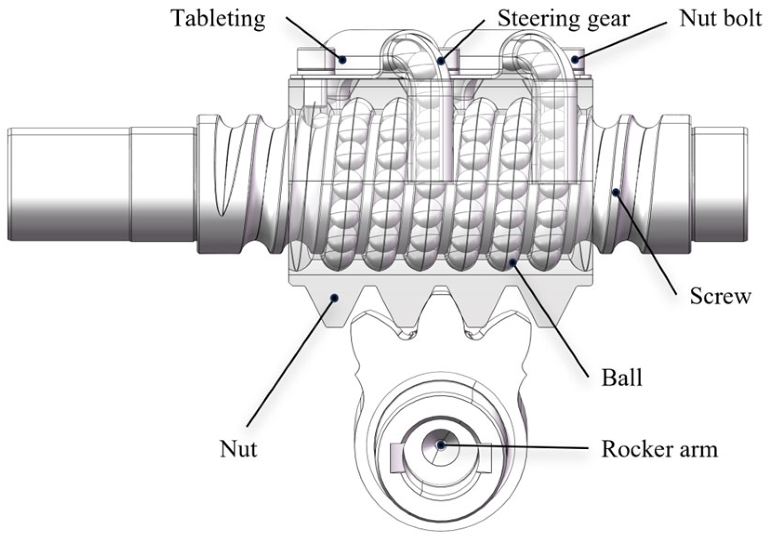
2. Main Parameters of XEPS Steering Gear

This study takes the XEPS steering gear as the research object, which is mainly composed of screw, nut, reverser, shell, rocker, and many small steel balls [18]. When the driver turns the steering wheel, this action is transmitted through the steering screw. The steering screw is connected to the steering shaft, and its rotational motion is transmitted through the internal thread of the nut. To reduce the friction between the screw and the nut, there is no direct contact between them. Instead, a series of small steel balls roll between the inner and outer raceways, and these steel balls circulate in the closed pipeline, converting the original sliding friction into rolling friction, thus significantly improving the transmission efficiency. The nut is equipped with two steel ball ducts, which are filled with steel balls and connected to the raceway. This design forms two independent closed channels for the steel ball to circularly roll. When the screw pushes the nut to move, the steel ball circulates and rolls in the conduit and raceway to transmit force effectively. In addition, a rack is arranged under the nut, which engages with the tooth fan on the steering rocker arm. When the nut moves along the screw, it pushes the rack, which in turn drives the tooth fan and the steering rocker arm connected to it to swing. This continuous action finally results in the steering of the wheel, ensuring that the vehicle can turn accurately in accordance with the driver’s intention.
An accurate 3D solid model is a guarantee of high reliability of simulation analysis results. The system solid model was created by Solidworks. The main parameters of the XEPS steering gear are shown in Table 1.
Finally, a simplified model of circulating ball steering gear is obtained, as shown in Figure 1.

3. Rigid–Flexible Coupling Dynamic Analysis

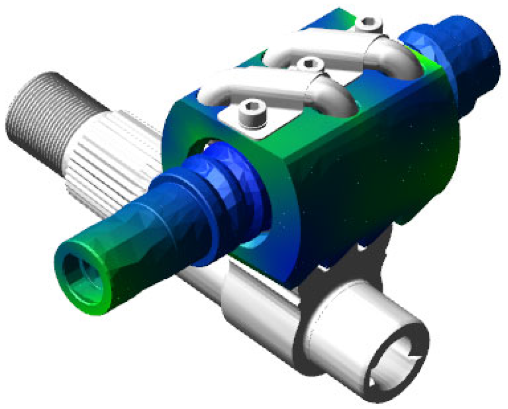
3.1. Establishment of Dynamic Model

The flexible body can be established by finite element method in ADAMS software. For the flexible parts, the material attributes are defined and meshed, the remote points are located, the code is set, the mode is analyzed, the mnf format file is obtained, and the rigid parts are converted into flexible parts when the file is imported into ADAMS. Among them, the screw–nut pair generates flexible parts, and its related deformation can be viewed in the process of simulation. The flexible parts are connected with other parts by constraint or contact, and the rigid–flexible coupling dynamic model of XEPS steering gear is obtained, as shown in Figure 2.
The material parameters set in ADAMS mainly include screw, nut, reverser, rocker, screw, tablet pressing, and so on. The material of the screw, nut, and rocker arm is 20CrMnTi, and the material of the steel ball is GCr15. The main related component parameters are shown in Table 2.
In ADAMS, when the impact function is used to select the impact function to calculate the normal meshing force, the user must input the deformation depth (penetration depth), viscous damping coefficient (damping), nonlinear index of force (force exponent), and stiffness coefficient (stiffness). In general, the parameters in the compensation method are more difficult to determine than those in the impact function. Therefore, the impact function is generally selected when calculating the ball contact and the normal meshing force of the gear. At the same time, ADAMS provides a variety of different contact types for users to choose from, such as solid to solid, curve to curve, point to curve, flex body to solid, etc. The impact function can be expressed as [19]:
F n = 0 q > q 0 k ( q 0 q ) e c max ( d q d t ) s t e p ( q , q 0 d , 1 , q 0 , 0 ) q q 0
where q 0 is the initial distance of the collision body, q is the actual distance of the collision body, d q / d t is the speed of colliding objects, k is the stiffness factor, e is the collision index, c m a x is the damping coefficient, and d is the depth of penetration.
This study aims at the contact between steel ball and screw, nut, reverser track and nut, and rocker rod. The contact between the steel ball and the steel ball is a ball contact; the raceway usually has a specific Radian, so this contact can be approximated to the contact between the sphere and the arc surface. In this case, Hertz’s contact theory can be used to calculate the equivalent radius and analyze the stress state and deformation of the contact surface. According to the Hertz contact theory, the contact area between the parts can be regarded as an elliptical area, and the contact stiffness K of each part can be expressed as [20]:
K = 4 3 R 1 2 E *
where R and E* are equivalent radius and equivalent elastic modulus, respectively. 1 R = 1 R 1 + 1 R 2 , 1 E * = ( 1 v 1 2 ) E 1 + ( 1 v 2 2 ) E 2 , R1 is the equivalent radius of part 1; R2 is the equivalent radius of part 2; E1 and E2 are the elastic modulus of part 1 and part 2, respectively; and μ 1 and μ 2 are the Poisson’s ratio of part 1 and part 2, respectively.
The contact stiffness of the XEPS steering gear can be calculated by the above formula. Considering that the tooth height and the indexing circle radius of the gear are relatively small, the equivalent radius at the contact point of the gear can be approximately replaced by the indexing circle radius, thus the equivalent radius R of the contact between the parts can be calculated. According to its material characteristics, the composite elastic modulus E of each part can be calculated, and then the contact stiffness K of each part can be calculated according to the Formula (2). According to the calculation, the contact stiffness between the steel ball and the steel ball is 6.0 × 10⁶ N/mm, the contact stiffness between the steel ball and the raceway is 7.4 × 10⁶ N/mm, the contact stiffness between the nut and the rocker arm is 2.1 × 10⁷ N/mm, the force index is 1.5, the damping coefficient is 100 Ns/mm, and the breakdown depth is 0.1 mm.

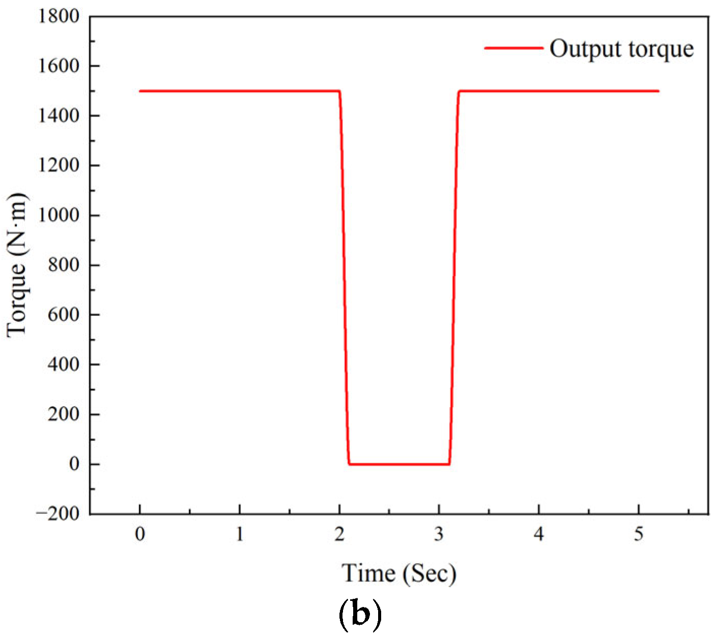
3.2. Working Condition Analysis

According to the operating instructions of the automobile XEPS steering gear and the durability test standard [21], the rotating speed of the screw was set to ±180°/s, and the rated torque of the rocker arm output was 1500 N·m. Because the forces acting on both ends of the screw and nut are basically similar, considering that the amount of simulation calculation is too large, this study circulated the ball steering gear from the middle position, the screw rotated to one side for 2 s, decelerated for 0.1 s, then stopped for 1 s, then accelerated for 0.1 s, then continued to rotate for 2 s, half a cycle, and calculated a total of 5.2 s. We used step function to realize the following: step (time, 0, 180 d, 2, 180 d) + step (time, 2, 0 d, 2.1, −180d) + step (time, 3.1, 0 d, 3.2, −180 d); the torque of the rocker arm was opposite to that of the screw: step (time, 0, 1500, 2, 1500) + step (time, 2, 0, 2.1, −1500) + step (time, 3.1, 0, 3.2, −1500), the speed and torque curves are shown in Figure 3.

3.3. Constraint Setup

In the geometric model imported into ADAMS, the included parts need to establish constraints, so the constraints between the parts should be defined according to the real working conditions. The constraint relationship between the zero parts of the XEPS circulating ball steering gear is shown in Table 3.

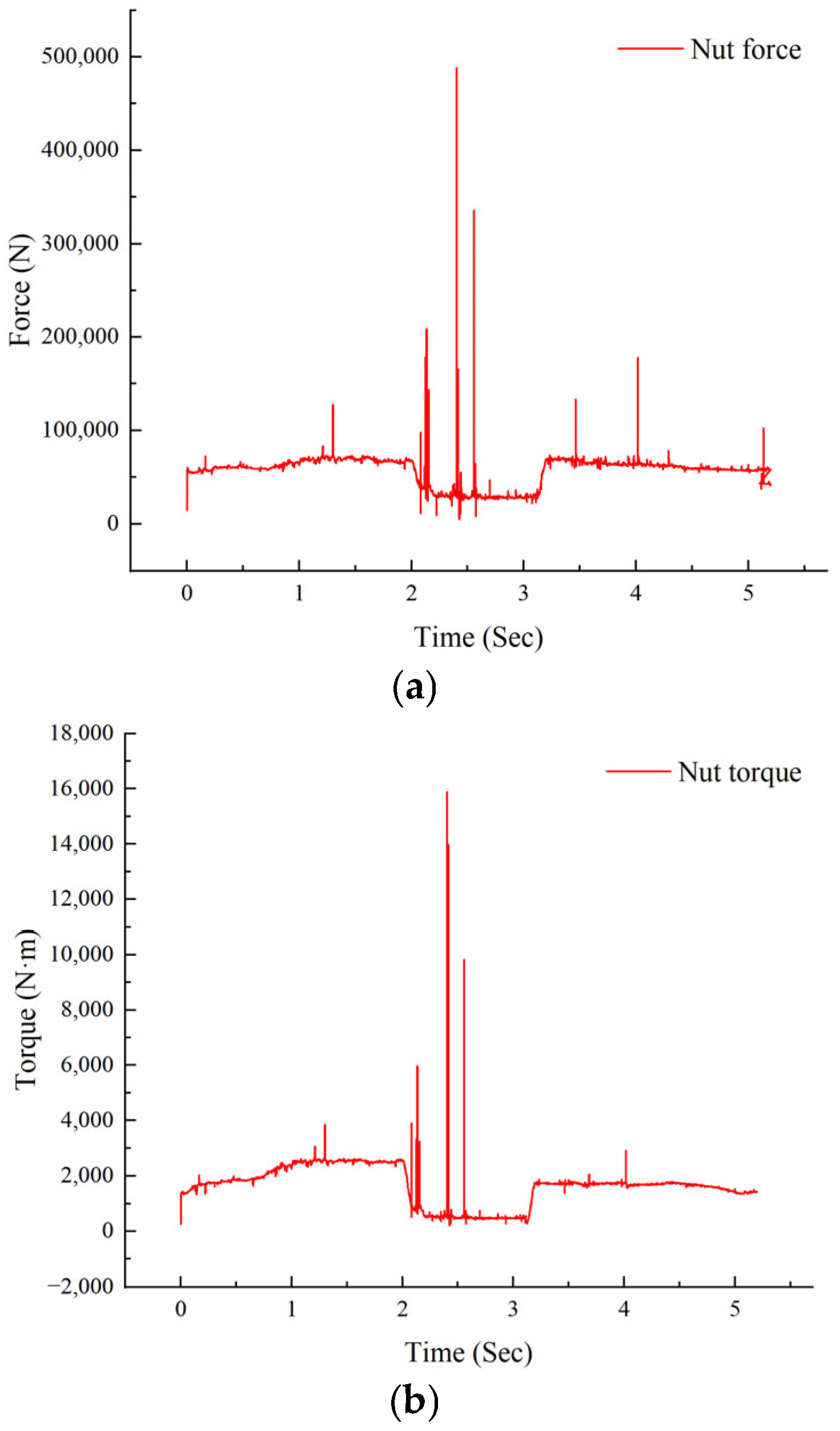
3.4. Dynamic Response Results

The contact forces related to steel balls are the contact forces between steel balls and screws, nuts, reversers, and adjacent steel balls, and the contact forces between nuts and rocker arms need to be added. The model included 100 steel balls, so a total of 501 contact forces were added. The parameters of the contact force need to be set when adding the contact force. The simulation time was set to 5.2 s and the simulation step was set to 1000 steps to study the load of the circulating ball steering gear under the limit working condition.
Figure 4 shows the rotational speed of the screw and rocker arm as a flexible body and affected by deformation. In the process of rotation, the screw speed fluctuates around 180°/s, while the rocker speed fluctuates around 10°/s. This shows that when the screw and rocker arm are running as flexible bodies, the dynamic characteristics caused by their own deformation lead to the fluctuation of their respective speeds.
Figure 5 shows the time-domain variation of the force and torque of the screw under ultimate working conditions. In the process of motion, the force and torque of the screw gradually increase, reaching the peak value of 6.3 × 10⁴ N and 2.1 × 10³ torsion at about 2 s, respectively, and at 2.1 s, the screw begins to decelerate and withstand a large deceleration until it stops rotating. Due to the influence of inertia, the singularity of the flexible body appears at 2.3 s, and then at 3.1 s, the screw rotates in the opposite direction and finally returns to the initial position to complete the half-cycle operation.
Figure 6 is the time-domain diagram of the force and torque of the nut under the ultimate working conditions. It can be seen from the diagram that the force and torque on the nut reach the highest values of 7.1 × 10⁴ and 2.5 × 10³ at about 2 s with the increase in rotation, and then the force and torque decrease and remain at a stable value. Under the influence of inertia, the nut’s flexible body is prone to large singularities around 2.1 s and 2.3 s; the nut moves in the opposite direction at 3.1 s; at 3.1 s, the rocker begins to reverse output torque until it returns to the equilibrium position.

4. Fatigue Life Analysis of XEPS Steering Gear

4.1. Finite Element Model

The SolidWorks model was exported to ANSYS. Considering the computational efficiency, the circulating ball whole is meshed by 5 mm, the rail feed grid of screw, nut, and converter was adjusted to 2 mm, and the steel ball was also 2 mm, as shown in the figure. According to the working condition of the circulating ball steering gear, the motion process of the recirculating ball steering gear was simplified and its related parts are constrained as shown in the table. In this study, the rotating speed of the screw was equivalent to the torque of the normal rotation of the screw, and the contact force between the rocker arm and the nut was equivalent to applying force on the nut.
In this study, through the static analysis of ANSYS Workbench, the boundary conditions are shown in Figure 7, and the load mapping was applied at the equivalent place, and finally imported into NCode, and the relevant results were obtained.

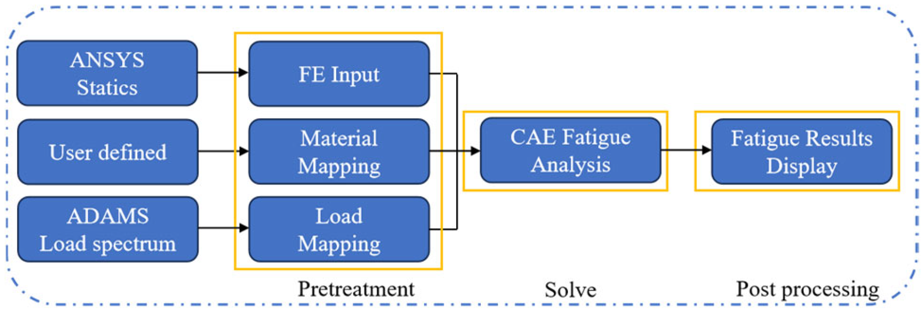
4.2. Fatigue Life Analysis

In the process of transmission, the track of the circulating ball steering gear screw and nut is prone to pitting corrosion, so the fatigue life of the track is studied in this study. Based on the nominal stress method, using the load spectrum obtained by dynamic simulation and the stress spectrum obtained by finite element analysis, the fatigue life was calculated by NCode Design Life 2021 software.
The basic process of fatigue life is shown in Figure 8.

4.3. Parameter Definition

In this study, the finite element results were imported into NCode Design Life, the load type was defined as time load series, and the statics results were associated with time. In the Time Series of NCode, the mapping expression of time load series is [22]:
σ i j ( t ) = k ( P k ( t ) S c a l e F a c t o r k + o f f s e t k ) σ i j . k , s t a t i c D i v i d e r k
where σ i j ( t ) is the time history stress in fatigue analysis; P k ( t ) is the input time series load spectrum; S c a l e F a c t o r k is the ratio coefficient of the load spectrum of time series; o f f s e t k is the load offset; σ i j . k . s t a t i c is the static stress result; and D i v i d e r k is the divider, with a value of 1; and k is the number of load steps of the real process.
In this study, there was a situation in which multiple loads acted together ( k > 1), The root carried on the linear superposition of each load according to the linear damage theory.
Considering the proportional coefficient in the load, the ratio factor expression of the material as a whole is [23]:
s = S F e n g ( O f f m a t i d + S F m a t i d σ s t a t i c ( S F l o a d P K ( t ) + o f f l o a d ) D I V l o a d )
where s is the population proportion coefficient; S F e n g calculates the example factor of the engine; O f f m a t i d is the coefficient of material compensation; S F m a t i d is the coefficient of material compensation; σ s t a t i c is the static stress result; D I V l o a d is the load divider; S F l o a d is the load scale factor; o f f s e t k is the load offset; P k ( t ) is the input time series load spectrum.
The screw nut pair material used in this study was 20CrMnTi, but there was no Smurn curve of this material in the default material library of NCode. Therefore, through the elastic modulus E and tensile strength limit UTS of the material, the Smurn curve of the material was estimated based on the empirical formula, and the SN curve is shown in Figure 9.
In this study, the default damage assessment was grounded in linear damage theory, where the underlying principle is linear superposition. As expounded in the work of Kobelev [24], in the realm of linear damage theory, the linear Miner theory stands as the most prevalently utilized approach. This theory posits that the damage accrued and the remaining life of components remain unaffected by the loading sequence. Instead, damage accumulates in a linear fashion.
The total damage is expressed as [25]:
D i = n i N i , N = 1 D i
where D i is the fatigue damage caused by all levels of load; n i is the number of cycles of all levels of load; N i is the fatigue limit times corresponding to all levels of load; and N is the total life span. When the cumulative damage reaches a certain limit, the component will be damaged.

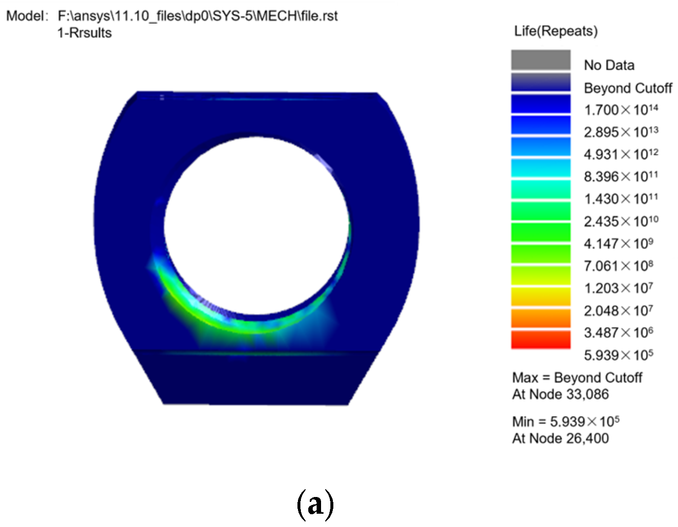
4.4. Research Result Analysis
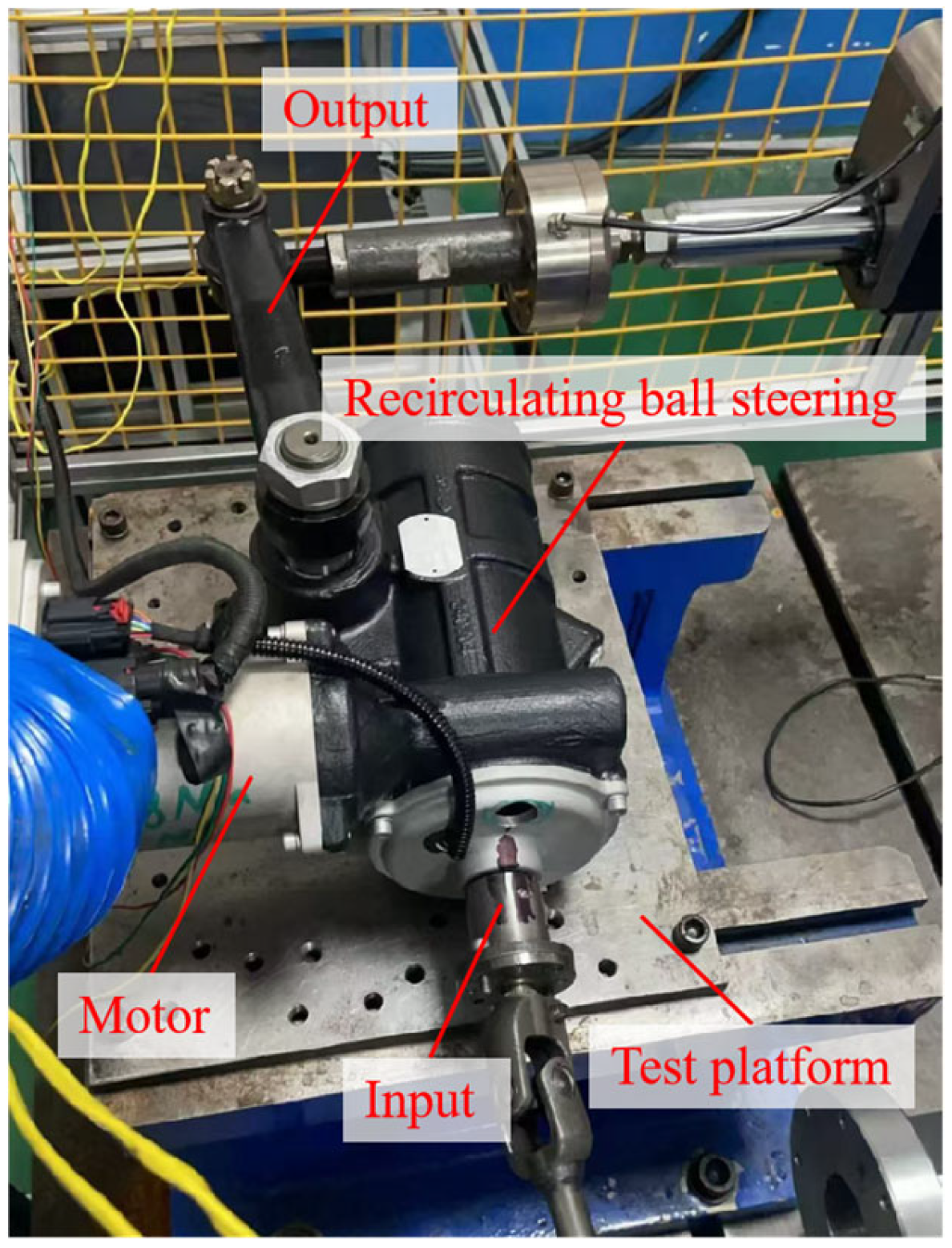
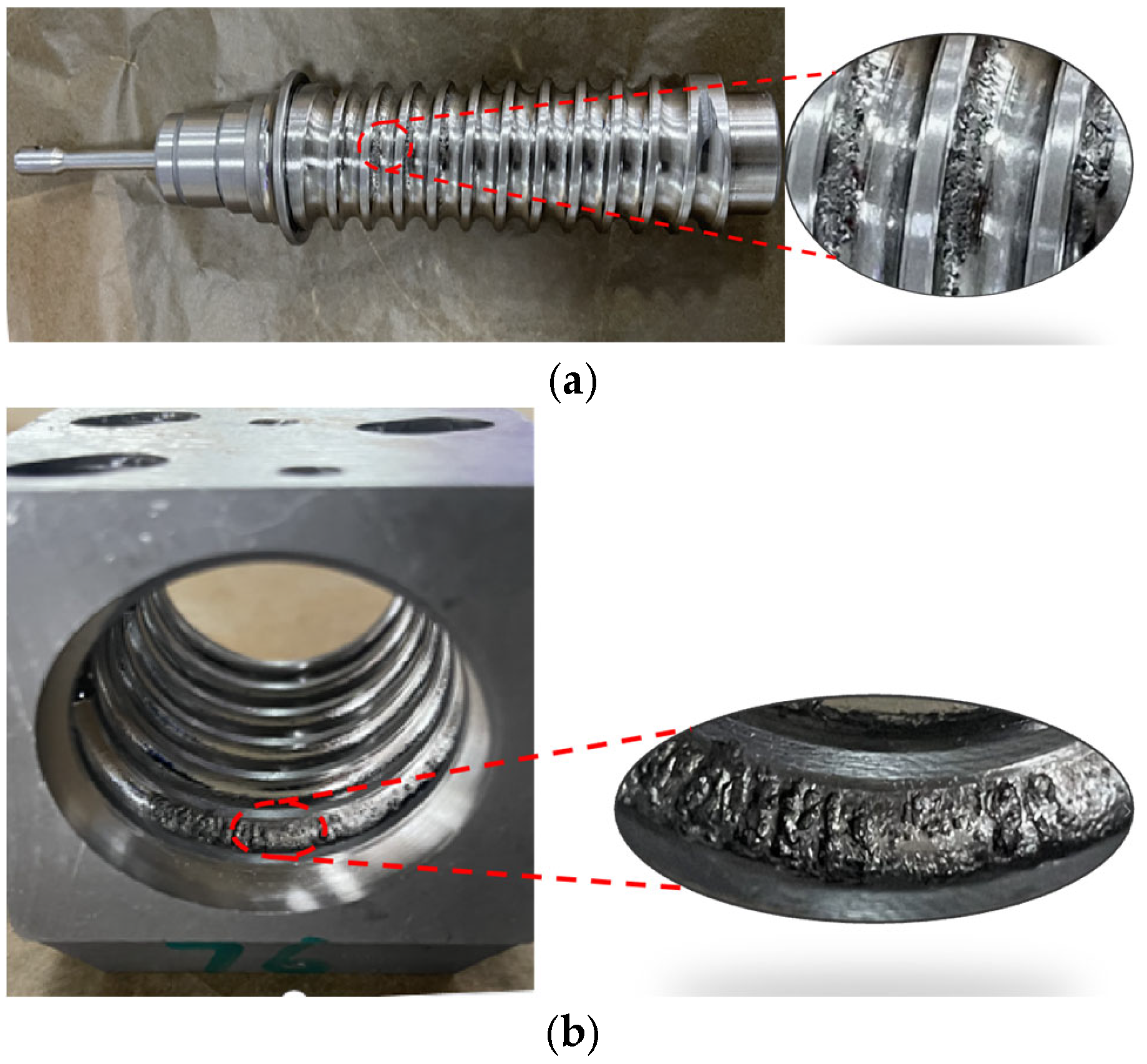
In this study, the Goodman mean stress theory was used to modify the input fatigue load. The survival rate was set to 95%; the time load history file (.s3t) and the statics result file (.rst) were imported into the “fatigue five diagrams” process, and finally analyzed with 20CrMnTi’s Smurn curve.
Nocde 2021 software flow chart, as shown in Figure 10.
According to the above operation, the fatigue life/damage of the key parts was obtained, as shown in the Figure 11.
As can be seen from Figure 11 above, the position where failure is most likely to occur is near the left track of the screw, which is consistent with the maximum deformation position of Adams dynamic simulation results. The maximum damage value of each cycle is 7.605 × 10⁻⁷, and the minimum number of cycles of the screw under this limit condition is 2.056 × 10⁵.
As can be seen from Figure 12, the place where the nut is most prone to failure is the lower part of the track, and the steel ball returns to the nut raceway from the reverser, resulting in a larger contact force, and the maximum damage value of each cycle is 2.868 × 10⁻⁷, the minimum number of cycles of the nut under this limit condition is 5.939 × 10⁵.
In this study, only half of the stroke was simulated, and the number of cycles needed to be reduced by half, so the minimum cycle times of the whole screw and nut were 1.028 × 10⁵ and 2.9695 × 10⁵ times, which are larger than 5 × 10⁴ times specified in the industry standard, so it meets the design requirements.

4.5. Bench Tests

Figure 13 shows a fatigue life test platform, which is mainly composed of key components such as motors, XEPS recirculating ball steerers, and sensors. The whole is fixed on the base of the bench by the designed fixture, and a series of operations such as starting, stopping, intermittent operation, load application, and cycle setting of the equipment can be effectively achieved through precise control of the motor speed during the test process. and displays the current number of cycles.
According to the actual working conditions of the XEPS cyclic ball steering gear, the fatigue test results show that the screw and nut are in contact with the rail fatigue pitting after a certain loading cycle, which is mainly manifested in the corrosion phenomenon of the steel ball track between the screw and the nut, as shown in Figure 14. Among them, the life cycle of the screw and nut is 106,589 and 283,643 cycles, respectively.
The finite element simulation prediction results were compared with the experimental results. The results of the analysis are shown in Table 4.
As can be seen from Table 4, the error between the finite element simulation prediction results and the experimental results is within 5%, which is theoretically within the acceptable range, which verifies the feasibility of the fatigue life analysis model of the XEPS recirculating ball steering gear.

5. Conclusions

This study integrated virtual prototyping and finite element theory to analyze the rigid–flexible coupling dynamics of a commercial vehicle X-EPS recirculating ball steering gear for fatigue life prediction of its screw and nut.
1. A rigid–flexible coupling dynamic model in Adams provided real-motion loads of the components. Finite element analysis in ANSYS and fatigue calculation in NCode Design Life showed that the minimum fatigue life cycle numbers of the screw and nut, after considering a full-stroke simulation, were 1.028 × 10⁵ and 2.9695 × 10⁵ times, respectively, meeting the industry standard of 5 × 10⁴ times.
2. Bench tests were conducted, and the results showed fatigue pitting on the screw and nut tracks. The error between simulation and experimental results was within 5%, verifying the feasibility of the analysis model and prediction method.
In conclusion, this research offers an effective way for predicting X-EPS steering gear fatigue life, which can assist automotive manufacturers in optimizing steering system design, and also serves as a reference for fatigue performance research of other automotive components.

Author Contributions

Conceptualization, F.C. and X.S.; Methodology, B.Q., X.S. and H.L.; Software, Z.F., C.S. and C.F.; Validation, F.C. and Q.Z.; Formal analysis, Z.F. and L.Y.; Investigation, L.Y.; Resources, F.C., B.Q. and C.F.; Data curation, Z.F., B.Q., C.S. and Q.Z.; Writing—original draft, H.L. and L.Y.; Writing—review and editing, F.C., C.S. and X.S.; Visualization, Q.Z.; Project administration, C.F., X.S. and H.L.; Funding acquisition, X.S. All authors have read and agreed to the published version of the manuscript.

Funding

This research was supported by the Research and application of key components for new energy vehicles-Research and application of wire controlled steering system for new energy vehicles (2022C01241), National Innovation Center of Advanced Dyeing & Finishing Technology (2022GCJJ11), the fellowship of China Postdoctoral Science Foundation (2022M712835), and the Research Project of State Key Laboratory of Mechanical System and Vibration (MSV202317).

Data Availability Statement

Data are contained within the article.

Acknowledgments

The authors would like to thank the useful comments and constructive suggestions from the handing editor and anonymous reviewers.

Conflicts of Interest

Authors Feng Chen, Zhiquan Fu, Baoxiang Qiu, Chenfeng Si, Qizhang Zhu, Chenli Feng and Huafang Liang were employed by the company Zhejiang VIE Science & Technology Co., Ltd. The remaining authors declare that the research was conducted in the absence of any commercial or financial relationships that could be construed as a potential conflict of interest.

References

  1. Ma, B. Structural Design and Optimization of Light Truck Steering System. Master’s Thesis, Dalian Jiaotong University, Dalian, China, 2022. [Google Scholar]
  2. Hu, P.; Gong, W.; Xie, G.; Zhong, L.; Liao, J.; Li, G. Control Strategy of Rocker Shaft assisted circulating Ball EPS system. J. Southwest Univ. Sci. Technol. 2023, 38, 75–83. [Google Scholar] [CrossRef]
  3. Wei, J.; Li, Z.Z.; Tian, H.B. A control and compensation strategy of the electric power recirculating ball steering system. Comput. Eng. Sci. 2020, 42, 138. [Google Scholar]
  4. Ma, Y.-J.; Zhou, X. Analysis on influencing factors of assist characteristic curve of circulating ball steering gear. Hydraul. Pneum. 2022, 46, 160–168. [Google Scholar]
  5. Li, B.; Wang, L.-Z.; Chen, C.; Yin, Z.; Su, R.; Chen, X. Finite element Analysis of key parts of Automobile circulating Ball steering Gear. Pract. Technol. Automob. 2020, 45, 113–115. [Google Scholar] [CrossRef]
  6. Bertolino, A.; Sorli, M.; De Martin, A. Performance evaluation of a Ball Screw mechanism through a multibody dynamic model. Mater. Res. Proc. 2023, 26, 183–188. [Google Scholar]
  7. Yue, X. Stress and Fatigue Analysis of Circulating Ball Power Steering Gear. Master’s Thesis, Huazhong University of Science and Technology, Wuhan, China, 2016. [Google Scholar]
  8. Lv, L.; Lu, C.; Chen, S.; Wang, W. Study on Load Distribution and Fatigue Elastic Life of Ball Screw under Ultimate Conditions. Appl. Sci. 2024, 14, 1966. [Google Scholar] [CrossRef]
  9. Hojjati-Talemi, R.; Abdel Wahab, M. Fretting fatigue crack initiation lifetime predictor tool: Using damage mechanics approach. Tribol. Int. 2013, 60, 176–186. [Google Scholar] [CrossRef]
  10. Ferjaoui, A.; Yue, T.; Abdel Wahab, M.; Hojjati-Talemi, R. Prediction of fretting fatigue crack initiation in double lap bolted joint using Continuum Damage Mechanics. Int. J. Fatigue 2015, 73, 66–76. [Google Scholar] [CrossRef]
  11. Kumar, D.; Biswas, R.; Poh, L.H.; Abdel Wahab, M. Fretting fatigue stress analysis in heterogeneous material using direct numerical simulations in solid mechanics. Tribol. Int. 2017, 109, 124–132. [Google Scholar]
  12. Xu, G.; Zhou, X.-Y. Effect of semi-active suspension on vehicle durability. J. Tongji Univ. (Nat. Sci. Ed.) 2022, 50, 10–15. [Google Scholar]
  13. Pichandi, M.; Mohan, B.; Jagadeesh, S.; Balaji, S. Conventional Four-bar Linkage Steering System Adoption for Underslung Front Suspension. ARAI J. Mobil. Technol. 2022, 2, 249–255. [Google Scholar] [CrossRef]
  14. Liu, J.; Liu, Y.-J.; Zhang, S.-H.; Yang, J.; Dong, Q. Study on fatigue Life of a medium truck Cab based on Virtual iteration and finite element Theory. Chin. Mech. Eng. Process 2018, 29, 1588–1595. [Google Scholar]
  15. Zhang, G.; Wei, Y.; Ju, C.; He, S. Multiobjective Optimization of Vehicle Handling and Stability Based on ADAMS. Math. Probl. Eng. 2022, 2022, 3245251. [Google Scholar] [CrossRef]
  16. Ashok Kumar, S.C.; Erikmats, E. Modelling and Control of Active Power Steering Systems for Heavy Trucks. Master’s Thesis, Chalmers University of Technology, Gothenburg, Sweden, 2023. [Google Scholar]
  17. Kuris, S.; Gungor, E.; Deniz, A.; Uysal, G.; Aykent, B. Kinematics and Compliance Analysis of a 3.5 Tonne Load Capacity Independent Front Suspension for LCV; No. 2019-01-0935; SAE Technical Paper; SAE: Warrendale, PA, USA, 2019. [Google Scholar]
  18. You, Z.; Li, R.; Liu, Q. Motor Control Strategy of Recirculating-Ball EHPS System for Bus Under Multi Working Conditions. Int. J. Simul.—Syst. Sci. Technol. 2015, 16. [Google Scholar] [CrossRef]
  19. Sun, X.-Q.; Shi, D.-W. Dynamic simulation and fatigue life prediction of transmission system of vertical ship lift. J. Wuhan Univ. (Eng. Ed.) 2016, 49, 610–615. [Google Scholar] [CrossRef]
  20. Long, K.; Cheng, Y. Research on Parameter selection of Simulation calculation of Gear Meshing Force. Comput. Simul. 2002, 19, 87–88. [Google Scholar]
  21. QC/T 29096-2010; Performance Requirements and Test Methods of Automobile Steering Rod Ball Head Assembly. Ministry of Industry and Information Technology: Beijing, China, 2010.
  22. Ma, J.; Wang, Z.T.; Zhou, D.; Liao, L.H.; Huang, Z. Analysis of wind-induced vibration and fatigue effects of a typical tower crane. J. Shanghai Jiaotong Univ. 2014, 48, 804–808. [Google Scholar]
  23. Lu, N.; Han, C.-R. Fatigue life analysis of tower crane jib based on ADAMS rigid-flexible coupling model. Mech. Electr. Program 2021, 38, 1003–1009. [Google Scholar]
  24. Kobelev, V. Effects of Mean Stress and Multiaxial Loading on the Fatigue Life of Springs. Eng 2023, 4, 1684–1697. [Google Scholar] [CrossRef]
  25. Ye, J.; Huang, J. Analytical analysis and oscillation control of payload twisting dynamics in a tower crane carrying a slender payload. Mech. Syst. Signal Process. 2021, 158, 107763. [Google Scholar] [CrossRef]
Figure 1. Recirculating ball steering assembly.
Machines 13 00218 g001
Figure 2. Dynamic model of rigid–flexible coupling of XEPS steering gear.
Machines 13 00218 g002
Figure 3. Extreme case curves. (a) Screw input rotation speed, angular velocity time-domain diagram. (b) Time-domain diagram of rocker boom output torque.
Machines 13 00218 g003aMachines 13 00218 g003b
Figure 4. Time-domain diagram of screw and rocker boom speed.
Machines 13 00218 g004
Figure 5. Screw simulation results. (a) Time-domain diagram of screw stress; (b) screw moment time-domain diagram.
Machines 13 00218 g005
Figure 6. Nut simulation results. (a) Nut force time-domain diagram; (b) nut moment time-domain diagram.
Machines 13 00218 g006
Figure 7. Boundary condition settings.
Machines 13 00218 g007
Figure 8. Basic process analysis diagram of fatigue analysis.
Machines 13 00218 g008
Figure 9. S-N curves of 20CrMnTi materials.
Machines 13 00218 g009
Figure 10. Five-block diagram of fatigue analysis.
Machines 13 00218 g010
Figure 11. Screw life/damage contour. (a) Screw life. (b) Screw damage.
Machines 13 00218 g011
Figure 12. Nut life/damage contour. (a) Nut life. (b) Nut damage.
Machines 13 00218 g012aMachines 13 00218 g012b
Figure 13. Fatigue life test bench.
Machines 13 00218 g013
Figure 14. Fatigue life test results. (a) Screw pitting diagram. (b) Nut pitting diagram.
Machines 13 00218 g014
Table 1. XEPS component parameters.
ParameterValue
Gear fan module/mm6.0
Rocker arm diameter/mm41
Nut length/mm81
Screw outer diameter/mm37
Steel ball diameter/mm8
Pitch/mm11
Gear fan pressure angle26.85°
Gear fan rake angle6.5°
Number of teeth on gear fan3
Table 2. Main material parameters of XEPS.
Material20CrMnTiGCr15
Density/(kg·m−3)7860.07830.0
Young’s modulus/GPa2.122.19
Poisson’s ratio0.2890.3
Yield strength/MPa835518
Compressive strength/MPa1080861
Table 3. Constraints of XEPS steering gear.
Serial NumberConstrain AssemblyConstraint Type
1Screw, groundRevolute joint
2Nut, groundPrismatic joint
3Rocker arm, groundRevolute joint
4Nut, return deviceFixed joint
5Nut, M6 boltFixed joint
6Nut, pressing tabletFixed joint
Table 4. Comparison of simulation results and test results.
ComponentSimulation/TimeExperimental/TimeError/%
Screw102,800106,5893.68
Nut296,950283,6434.48
Disclaimer/Publisher’s Note: The statements, opinions and data contained in all publications are solely those of the individual author(s) and contributor(s) and not of MDPI and/or the editor(s). MDPI and/or the editor(s) disclaim responsibility for any injury to people or property resulting from any ideas, methods, instructions or products referred to in the content.

