Article

The Optimized Design and Principal Analysis of a Toe-End Sliding Sleeve

1
Institude of Petroleum Engineering, Northeast Petroleum University, Daqing 163318, China
2
Key Laboratory for Enhanced Oil & Gas Recovery of the Ministry of Education, Daqing 163318, China
3
National Engineering Research Center of Oil & Gas Drilling and Completion Technology, Beijing 102206, China
4
School of Mechanical Science and Engineering, Northeast Petroleum University, Daqing 163318, China
*
Author to whom correspondence should be addressed.
Machines 2025, 13(3), 253; https://doi.org/10.3390/machines13030253
Submission received: 20 February 2025 / Revised: 15 March 2025 / Accepted: 18 March 2025 / Published: 20 March 2025
(This article belongs to the Special Issue Design Methodology for Soft Mechanisms, Machines, and Robots)

Abstract

:
Through hydraulic control principles, numerical simulation and indoor testing, the opening principle of a toe-end sliding sleeve with a time delay mechanism is explained. Conventional toe-end sliding sleeve in shale oil wells have problems with premature opening and a failure to open, which means they cannot ensure the whole-well pressure test process and can cause serious economic losses to the oil and gas industry. In order to solve the above problems, a new type of optimal design for toe-end sliding sleeve with a 30 min delayed opening is proposed. In this paper, based on the principle of hydraulic flow, ABAQUS 2022 numerical simulation software was used to study the influence of different states and the same hydraulic pressure on its internal stress–strain value. A qualitative study of the delayed-opening function was carried out using a pressurized pump unit. In addition, principle tests under different operating parameters were designed to quantitatively analyze the pin shear situation and the delayed opening time of the toe-end sliding sleeve when the tool was fitted with different numbers of pins and when the delay valve was fitted. In addition, the simulation results of the hydraulic fluid’s flow inside the time delay mechanism with different nozzle diameters were compared with the theoretical values, which showed that the hydraulic fluid’s flow rate inside the mechanism increased with the enlargement of the nozzle diameter, and the optimal nozzle diameter was 0.56 mm. The indoor test showed that when the tool was retrofitted with a time delay mechanism, installing six pins was the optimal combination. The field application of the slip-on was able to satisfy an opening time delay of 28.3 with a relative error of only 5.67%. These results complement the research on toe-end sliding sleeve and provide ideas for the optimization of toe-end slipcovers incorporating a time delay mechanism.

1. Introduction

As oil production projects gradually enter the stage of unconventional oil and gas production, horizontal-well fracturing production technology has become one of the most important means of unconventional oil and gas production [1,2,3,4]. After years of development, the toe-end sliding sleeve, as one of the key tools in downhole staged fracturing technology, has been applied in various well conditions such as open-hole wells and cased wells [5,6,7]. Without changing the existing cementing process, this technology does not require perforation or other tools after the cementing slurry solidifies. The toe-end sliding sleeve can be opened by holding pressure at the wellhead to establish the first stage of the horizontal-well fracturing channel, and makes it possible to directly perform fracturing operations or lower other downhole tools such as auxiliary logging instruments to the bottom of the well, which can effectively replace the first stage of perforation operations [8,9,10]. It successfully solved the problem that the later operation tools such as perforating guns and logging instruments in long horizontal wells could not be lowered to the bottom of the well. On the other hand, compared with the continuous tubing transmission perforation method, this tool has the advantages of high operation timeliness, low cost, low risk, unlimited operation depth, and no limit on the length of the horizontal section [11].
Before fracturing the reservoir, an integrity test for the casing in the entire wellbore must be carried out to ensure its safety. Therefore, many oil companies in Europe and the United States have designed and developed sliding sleeves of various sizes and types with delayed opening (including electric control and hydraulic control). Among them, the Elect fracturing sleeve launched by Halliburton [12] has various forms. It overcomes the defects of conventional sleeves and can flexibly activate the target layer to improve the increase in production. The i-Opener TD sliding sleeve developed by National Oilwell Varco [13] can be used for repeated full-wellbore pressure testing. The Toe-XT hydraulic sleeve launched by Packers Plus [14,15,16] can be used for various operations including diameter and horizontal well pressure testing and selective fracturing. Schlumberger’s TAP casing valve fracturing completion system [17], Weatherford’s I-Ball sliding sleeve [18], and Baker Hughes’ Ooti Port sleeve [19] are all differential-pressure sleeves. BJ’s Opti Port cementing sleeves mainly include fracturing sleeves and downhole assembly tools (BHAs). The sleeves are hydraulically opened, with a hydraulic cylinder formed between the outer shell and the body. The inner sleeve slides open under the drive of the hydraulic pressure. These products have been provided to oilfield service companies in Europe and the United States for oilfield applications and have achieved the expected results.
Although toe-end sliding sleeves have been successfully applied in many oil fields in Europe and the United States with good results, European and American countries have imposed a technology blockade on Asian countries. Some bottleneck technologies are not open to Asian countries, and only technical services are provided. At the same time, high technical service fees are required, which has prevented Asian scholars from conducting research on them [20,21,22,23,24,25,26]. Liu Hailong et al. [27] studied toe-end sliding sleeve technology to solve the problems caused by rubber plug perforation in horizontal wells and designed a toe-end sliding sleeve tool with a compressive strength of 132 MPa and adjustable opening pressure. This solved the problem of coiled tubing being unable to perforate and saved completion operation time. Zheng Ruiqiang [28] briefly explained the advantages of toe-end sliding sleeves in the application of domestic shale oil well exploitation, analyzed the principle of toe-end sliding sleeves in Daqing Gulong shale oil, listed the field applications of toe-end sliding sleeves in shale oil, and put forward specific optimization measures and improvement suggestions for the tool. Liu Ben [29] developed an electronic toe-end sliding sleeve that can be remotely triggered to open through a customized pressure waveform and unlock the electromagnetic hydraulic lock by identifying the pressure waveform signal. The maximum test pressure can reach 98 MPa. In order to meet the increasing number of staged wells in China and the demand for fracturing tools, Liu Tao et al. [30] designed a ball-throwing sandblasting sleeve with unlimited stages of the same size. However, the difference in the size of the balls reached 3.18 mm ( 1 8 in ), and currently no manufacturer in China can produce such sealing balls, resulting in the key components of the tool still relying on imports. Hu Yaofang et al. [31] analyzed the reasons for the low opening rate of differential-pressure sleeves in China and used mechanical drawing software to improve the structure of differential-pressure sleeves. The improved differential-pressure sleeve increased the opening success rate, but the tool could not achieve the casing pressure test function. Yang Jie [32] drew on the research results of European and American companies to design key technologies, such as the delay function of the toe-end sliding sleeve, the inner sleeve positioning mechanism, the sealing method, the circulation hole size and the sleeve coating layer, determined the specific structure of the toe-end sliding sleeve that can be tested and optimized the relevant dimensions. Wei Liao [33] optimized the structure of a toe-end sliding sleeve differential-pressure sleeve based on field application conditions and improved the toe sleeve’s structure. Although the tool has a delay function, it needs to be pressurized slowly during the casing pressure test to prevent the dynamic pressure generated by the rapid change in displacement from causing damage to the rupture disk and causing the sleeve to open prematurely. Zhao Guangmin et al. [34] used a testable pressure toe sleeve in the integrated process and tubing system of gas field vertical wells. The study adopted a combination of “starting disk + soluble disk” to design a testable pressure toe sleeve. After the starting disk of the sleeve is broken, the soluble disk contacts the liquid in the well and dissolves quickly, connecting the casing with the formation and establishing the first section of the fracturing channel. Wang Bin et al. [35] designed an intelligent electrically controlled toe-end sliding sleeve and verified its ability to be opened effectively and accurately through indoor tests and numerical simulation. Xu Chaoqi [36] discussed the abnormal conditions of the toe-end sliding sleeve tool in the production of oil and gas in the Fuling shale field, analyzed the causes of the abnormalities from the aspects of the toe-end sliding sleeve body and the rubber plug body, put forward improvement suggestions and provided guidance for the improvement and application of the toe-end sliding sleeve in the later stage of the gas field. Wang Junji et al. [37] established a calculation model for the opening pressure of a pressure sliding sleeve, derived the calculation of the opening pressure of the pressure sliding sleeve with friction taken into account and concluded that the calculation results that consider friction theory are basically consistent with the experimental calculation results. Zhao Zhengxian et al. [38] conducted cementing sliding sleeve fracturing tests on the GY5-1-9H well, compared single-cluster and multi-cluster hole fracturing simulation tests and summarized the adaptability, mechanism and fracturing construction experience of single-cluster hole fracturing in continental shale oil in fault basins. This technology created the highest record of first-year cumulative oil production and single-well EUR in a normalized kilometer section of shale oil horizontal wells in China. In order to ensure the continuity of fracturing operations. Wang Xuxing et al. [39] proposed a new completion fracturing sleeve technology and developed a seawater-based integrated fracturing fluid system to meet the needs of large-volume annular operations. Liu Dongliang et al. [40] proposed a new first-stage fracturing process to solve the problems of complex procedures, low efficiency, high operating costs and high construction risks in the first-stage fracturing of unconventional oil and gas horizontal wells. This technology is widely used in unconventional oil and gas fields in North America. The cost of solving the problem for a single well is about US$300,000, and the success rate of the first-stage fracturing is increased to more than 98%. Liu Chuanyu et al. [41] briefly introduced new progress in the fracturing tools and technologies of international oil giants and put forward suggestions for the future development of fracturing tools and technologies in Asian countries. Xue Xianbo et al. [42] proposed an infinite-stage cementing sliding sleeve, established a three-dimensional dynamic numerical model of the dart rubber sleeve and studied the influence of the anti-burst ring structure and the rubber sleeve structure on the sealing performance. Chu Yingjie et al. [43] introduced a solution that uses a single-pipeline hydraulically controlled sliding sleeve as a downhole control module to achieve intelligent completion functions. This solution has been successfully used in the offshore oil fields of the China National Offshore Oil Corporation, solving the problem of the intelligent control of large downhole diameters and adjustable openings, and has achieved good results. Zhou Bocheng [44] conducted an analysis of the abnormal opening of infinite-stage sliding sleeves, classified the abnormal opening types during fracturing construction, and proposed corresponding improvement measures and fracturing construction treatment measures.
The casing pressure test is the last step in well completion and is crucial to the integrity of the wellbore. However, the conventional differential-pressure sliding sleeve without an improved structure cannot complete the full wellbore pressure test before fracturing. Based on the principle of hydraulic control and the shortcomings and defects of the sliding sleeve tool summarized by domestic researchers, a delayed-opening pressure test toe-end sliding sleeve was designed. In order to intuitively compare the performance of existing commercial products and the proposed model at this stage, so that readers can more clearly understand their differences, including their design, mechanism or performance, a table is drawn as shown in Table 1.
The finite element method can simulate various geometrically complex structures and obtain their approximate solutions. Through the use of computer programs, it can be widely used for various circumstances. It can import models built in other CAD 2022 software. Mathematical processing is relatively convenient and can also be applied to structures with complex shapes. The finite element method is combined with the optimization design method to give full play to their respective advantages. On the other hand, finite element calculation, especially the analysis and calculation of complex problems, consumes a lot of computing resources such as computing time, memory and disk space. There is no better way to deal with the problem of the infinite solution domain. Although most of the existing finite element software uses network-adaptive technology, in specific applications, what type of unit to use and how large the network density are both depend on the experience of the user. This article uses ABAQUS 2022 engineering software and the finite element method to carry out the numerical simulation of the main components of the tool, and combines indoor tests to verify the feasibility of its application, and then the verified tool is applied on-site. This new toe-end sliding sleeve can not only serve as the first-level fracturing channel to open the reservoir, but can also ensure the normal casing pressure test and greatly improve the stability of the wellbore. This provides a reference for the design and application of toe-end sliding sleeve tools that meet the needs of the casing pressure test before the completion process.

2. Technical Analysis

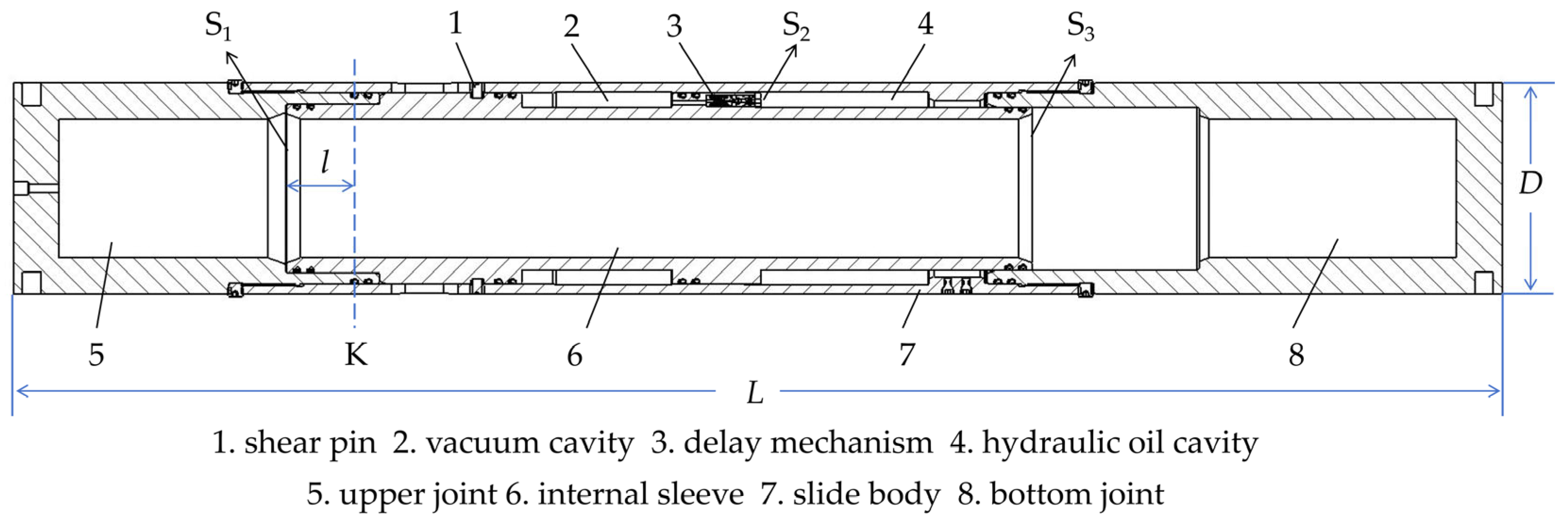
2.1. Structural Design

The structure of the delayed-opening toe-end sliding sleeve prototype is shown in Figure 1. Its structure is divided into two parts: a control mechanism and a delay mechanism. The control mechanism includes the sliding sleeve body, inner sliding sleeve, upper joint and lower joint, shear pin and sealing structure, which are used to control the opening of the sliding sleeve inside the tool. Its specific dimensions are shown in Table 2. The delay mechanism is composed of a flow-limiting valve and a pressure-limiting valve.

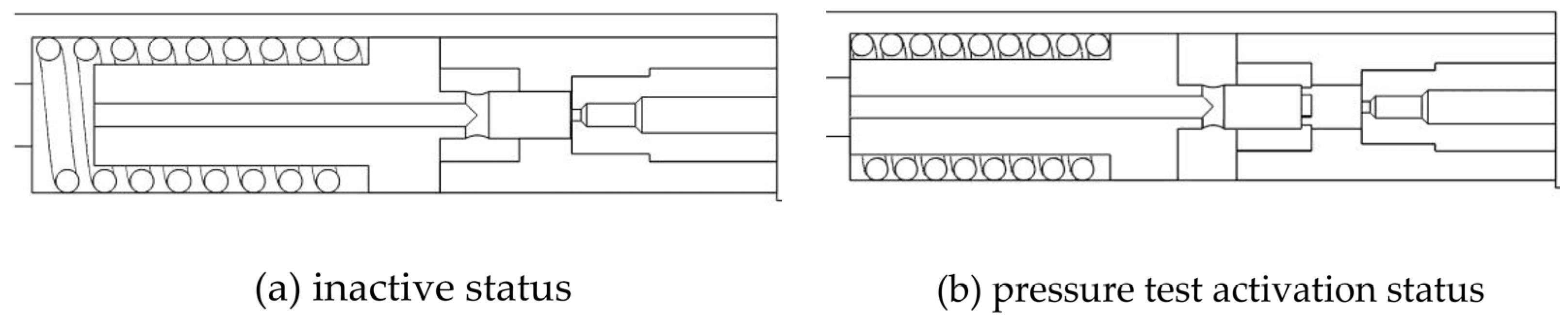
2.2. Working Principle

The pressurizing device generates hydraulic pressure inside the prototype. Since the cross-sectional relationship between the upper and lower end faces of the inner sleeve is S1 > S3, when the pressure difference F1F3 > the shear strength of the pin is generated, the pin is sheared and damaged, the delay mechanism opens and the hydraulic oil flows from the right oil chamber of section S2 to the left vacuum chamber. Due to the presence of hydraulic oil in the annular cavity, the inner sleeve moves slowly to the right and the toe-end sleeve’s opening is delayed by reasonably designing the equivalent diameter of the delay mechanism nozzle.
When the pressure in the tool is less than the preset opening pressure, the delay mechanism is in an inactive state, as shown in Figure 2a, and the toe-end sleeve is in a closed state. When the pressure in the tool reaches the preset pressure, the delay mechanism is activated, as shown in Figure 2b, and the sleeve is in a pre-opening state.

3. Numerical Simulation Methods

3.1. Numerical Simulation Equations

Since the equilibrium equation describes the equilibrium state of an object under the action of external forces, for static problems, the equilibrium equation is usually expressed as:
[M]{X} = {FC}
where [M] is the stiffness matrix, {X} is the displacement vector and {FC} is the force vector.
The constitutive equation describes the relationship between stress and strain of a material and is the key to understanding the behavior of a material. The constitutive model is expressed as:
σ = Εε
where E is the elastic modulus of the material, σ is the stress and ε is the strain.
For elastic-plastic analysis, the material’s constitutive relationship is selected based on the measured data from material tests.
Geometric equations describe the geometric shape and deformation of an object, usually involving the description of the displacement field. The displacement field can be expressed as:
u ( x , y , z ) = u x u y u z
where ux, uy and uz represent displacement components.
The Johnson–Cook damage model uses cumulative plastic strain to measure the degree of material damage. When the material is subjected to dynamic loading, as the plastic strain increases, damage gradually accumulates inside the material, eventually leading to failure. The conditions for damage occurrence are controlled by a failure strain (or damage parameter), and the damage evolution of the material under states of strain, temperature, and triaxial stress is considered. The failure strain formula is defined as:
ε c = ( a 1 + a 2 e ( a 3 σ * ) ) ( 1 + a 4 ln ε * ) ( 1 + a 5 T * )
where εc represents the failure strain; a1, a2, a3, a4 and a5 are material constants; σ* is the triaxial stress ratio (equal to pressure/stress); ε* is the normalized strain rate; T* is the normalized temperature.
In the Johnson–Cook damage model, the damage variable N is used to describe the damage evolution and is defined as:
N = Σ Δ ε l Δ ε c
where N is the plastic strain increment in each increment; when N = 1, the material reaches a state of failure. As the plastic strain increment accumulates, the N value gradually increases until it reaches 1, indicating that the material damage has accumulated enough to cause fracture.

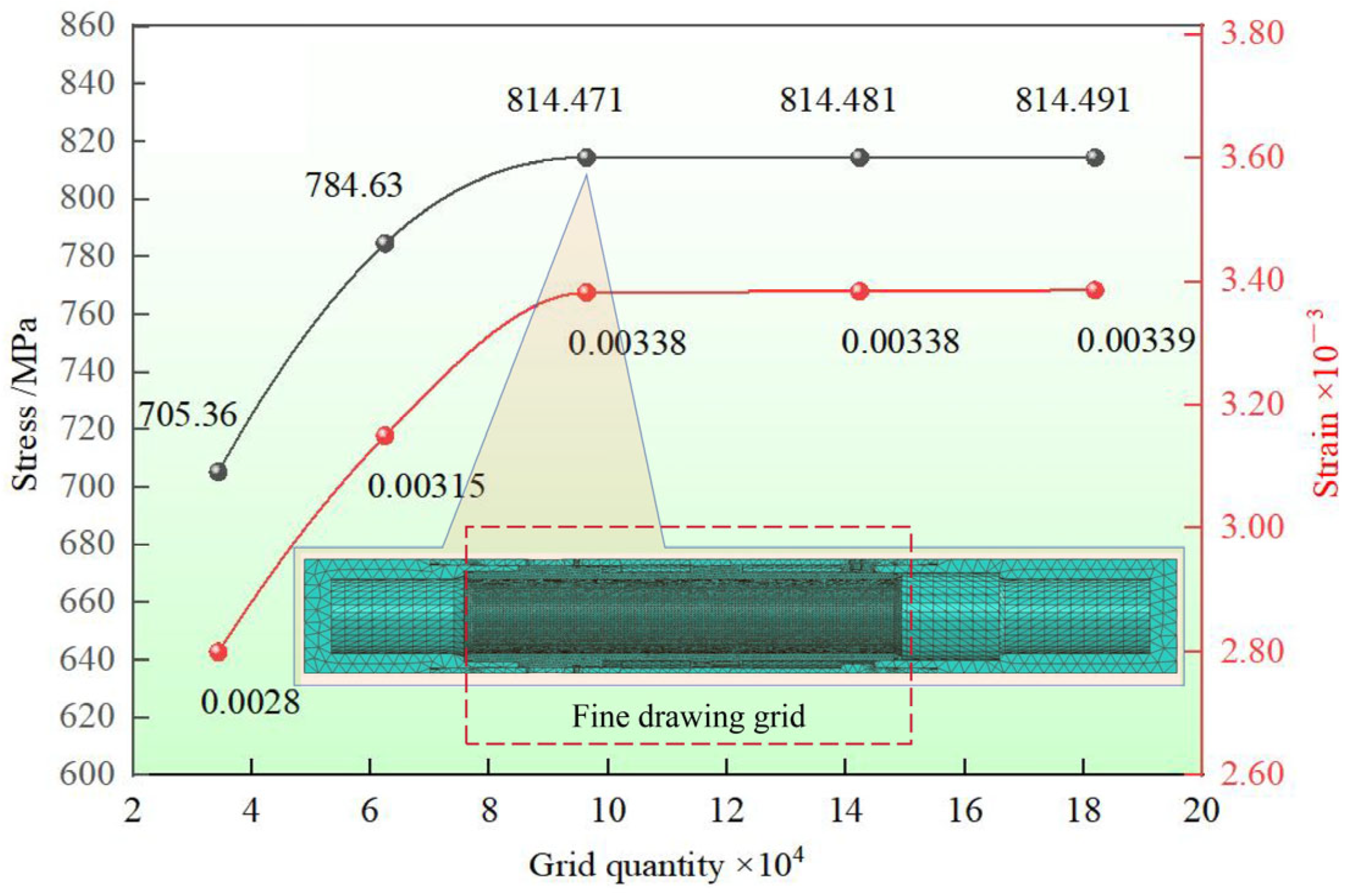
3.2. Meshing and Boundary Condition Setting

The number of grids will affect the calculation results. Too few grids will affect the calculation accuracy, but too many grids will reduce the calculation speed. When the number of grids reaches a certain level, the calculation results will no longer change with the change in the number of grids.
In order to ensure the accuracy of the finite element model simulation analysis, five mesh-level analysis models were established. The stress and strain occurring in the toe-end sliding sleeve were used as reference indicators, and a mesh independence check was performed. The mesh independence test results were tested and the structural model with mesh number 96,382 was selected for numerical simulation through the test results, as shown in Figure 3.
In order to obtain more accurate data through numerical simulation, the mesh quality is improved by using the fine mesh division method. The mesh of the inner sleeve model is encrypted. The mesh type is an eight-node linear polyhedron unit, the mesh size is 3 mm and 8.5 mm non-structured mesh is selected for other areas.
The above-mentioned delayed-opening toe-end sliding sleeve prototype was modeled in proportion using ABAQUS 2022 engineering software, and numerical simulation was performed using the finite element method. The simulation used a standard display solver, and the simulation medium was 42 CrMo steel with a yield strength of 930 MPa. The density is 7.85 × 10³ kg/m3, the Poisson’s ratio is 0.3 and the elastic modulus is 210 GPa. The outer body is bound to the inner sleeve, and contact and interaction are set between other components (the tangential friction coefficient is 0.2, normal “hard contact”), fixed boundaries are applied to the outside and both ends of the body and a hydraulic pressure of 110 MPa is applied to the inner sleeve and the body. The boundary conditions are shown in Figure 4.

4. Results and Discussion

In order to ensure that there is no structural damage when hydraulic pressure is applied inside the toe-end sliding sleeve prototype, the pins can be sheared off smoothly under the set internal pressure, and the delay time of 30 min is met, which are necessary conditions to achieve the design expectations; numerical simulation and theoretical calculation methods were used to carry out the feasibility analysis of the prototype tool and the determination of the equivalent diameter of the nozzle in the delay mechanism.

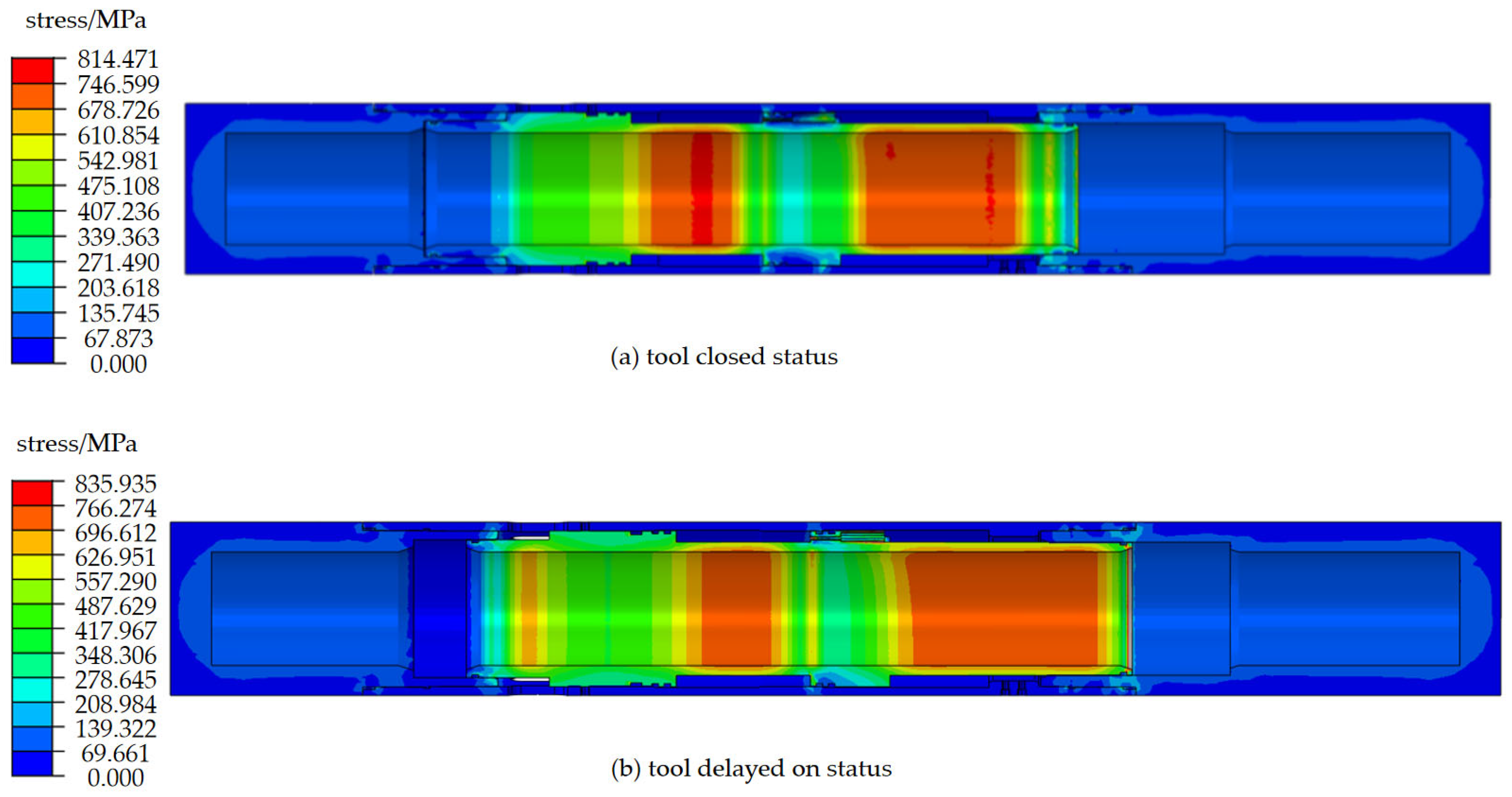
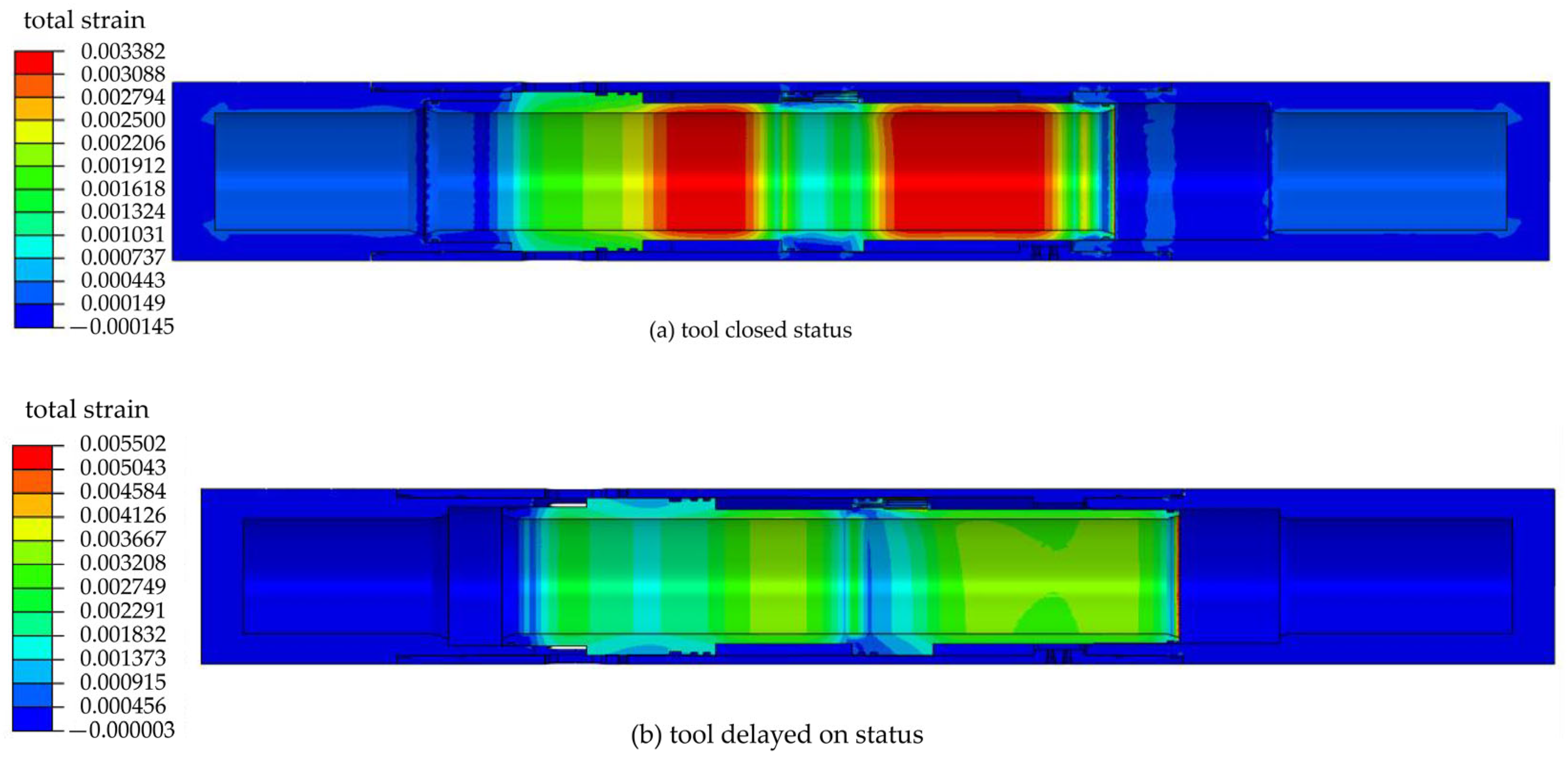
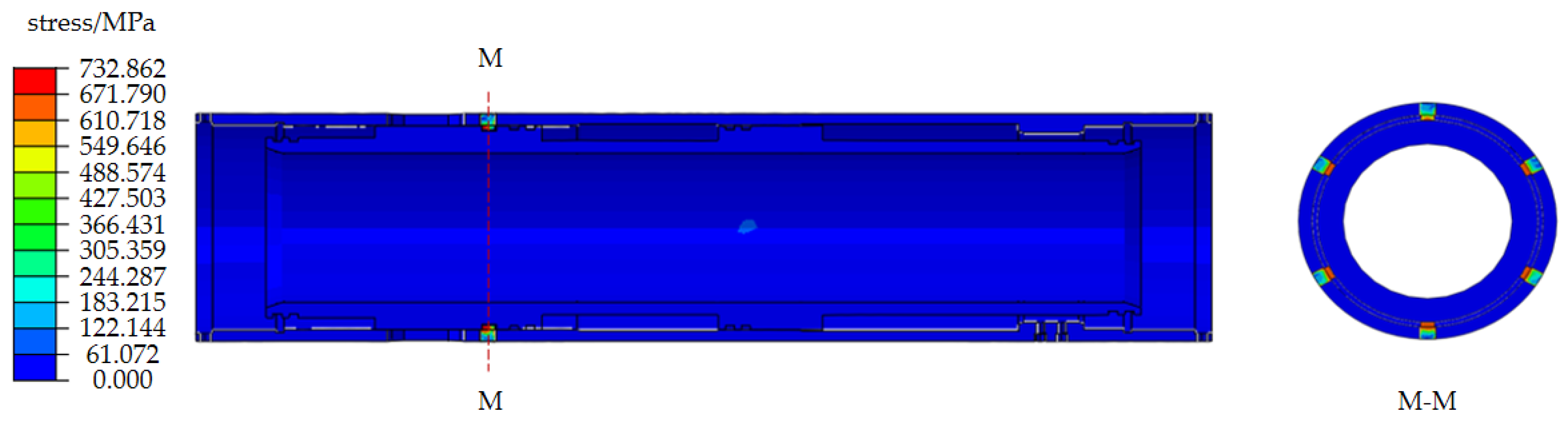
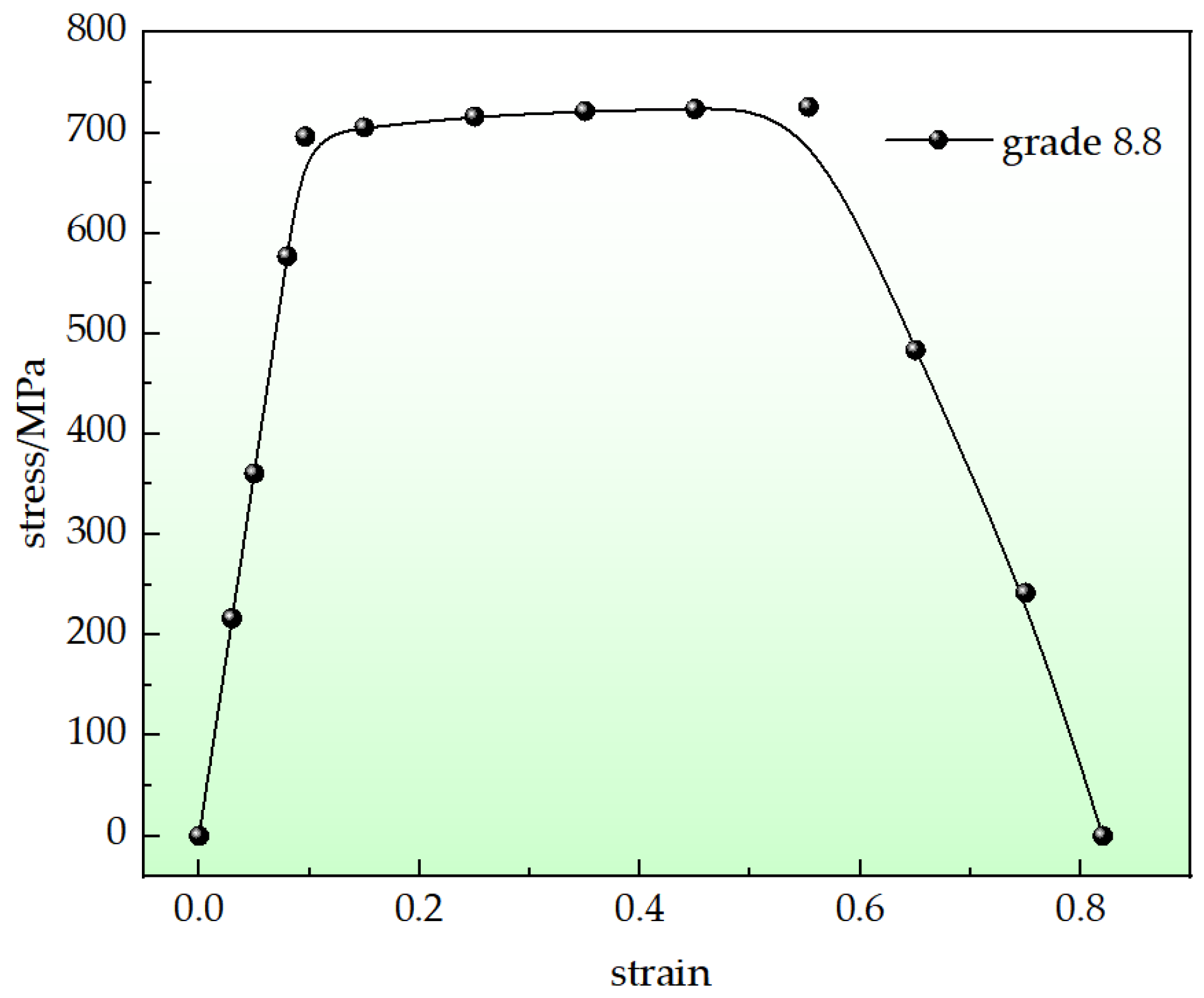
4.1. Tool Safety Performance Analysis

Through the above numerical simulation operation parameter settings, the stress cloud diagram of the toe-end sliding sleeve prototype under internal pressure was obtained, as shown in Figure 5.
It can be concluded from Figure 5a,b that when the hydraulic pressure in the tool is 110 MPa in different states, the equivalent stress in the tool delay process is relatively large, with a specific value of 835.935 MPa. Since the yield strength of the inner sleeve is 930 MPa and the strength limit is 1080 MPa, it is obvious that 835.935 MPa < 930 MPa < 1080 MPa, and the safety factor is 1.11. This shows that under this working condition, all components in the toe-end sliding sleeve did not yield, but only underwent a certain elastic deformation, which met the working requirements.
In order to verify the accuracy of the above simulation, the deformation degree of the prototype tool under internal pressure was numerically simulated, and the simulation results are shown in Figure 6a,b.
Whether the tool is closed or opened, the position of the maximum strain value in the tool is the same as the position of the maximum stress value, which shows the accuracy of the numerical simulation results. On the other hand, the strain value in the process of opening the sleeve is larger than that in the process of closing the sleeve, and its strain value is 5.5 × 10⁻³.

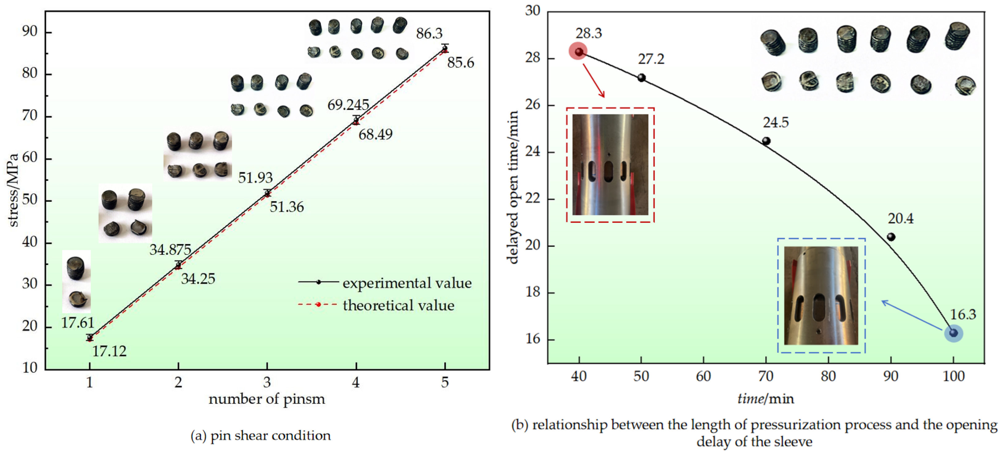
4.2. Shear Pin Failure Simulation Analysis

In order to clarify whether the inner sleeve can successfully shear off the pins when the full-size prototype is subjected to internal pressure, numerical simulation was carried out and the stress cloud diagram of the six pins during shearing was obtained, as shown in Figure 7.
When the inner sleeve has a tendency to move to the right, the six 8.8-grade M10 pins in the M-M section are evenly stressed, which indicates that the pin positions are reasonably arranged.
In order to further depict the specific process of pin shearing in detail, the simulation results of the pin at the M-M section of the full-size sliding tool are extracted, as shown in Figure 8.
It can be seen from the figure that during the process of the inner sleeve shearing the pin, the pin began to be stressed until it sheared, which took 0.25 s. When the time was 0.05 s, the pin pre-stress point was reached, and the middle part of the pin was greatly affected by the shear force. At this time, the maximum stress in the pin was 732.862 MPa; when the time was 0.1 s, the shear force extended to the lower end; when the time was 0.15 s, shear tearing occurred in the middle of the pin; when the time period reached 0.2~0.25 s, the pin was instantly shortened, and the force on the lower end of the pin was reduced to 244.387 MPa.
In order to intuitively obtain the relationship between the pin’s failure and the shear force, the stress–strain curve of the pin under shear force during the movement of the inner sleeve is plotted, as shown in Figure 9.
It can be concluded from Figure 9 that when the stress is less than 650.34 MPa, the pin undergoes elastic deformation. At this time, the internal deformation of the pin is small; when the stress continues to increase to 732.862 MPa, the pin undergoes shear failure.

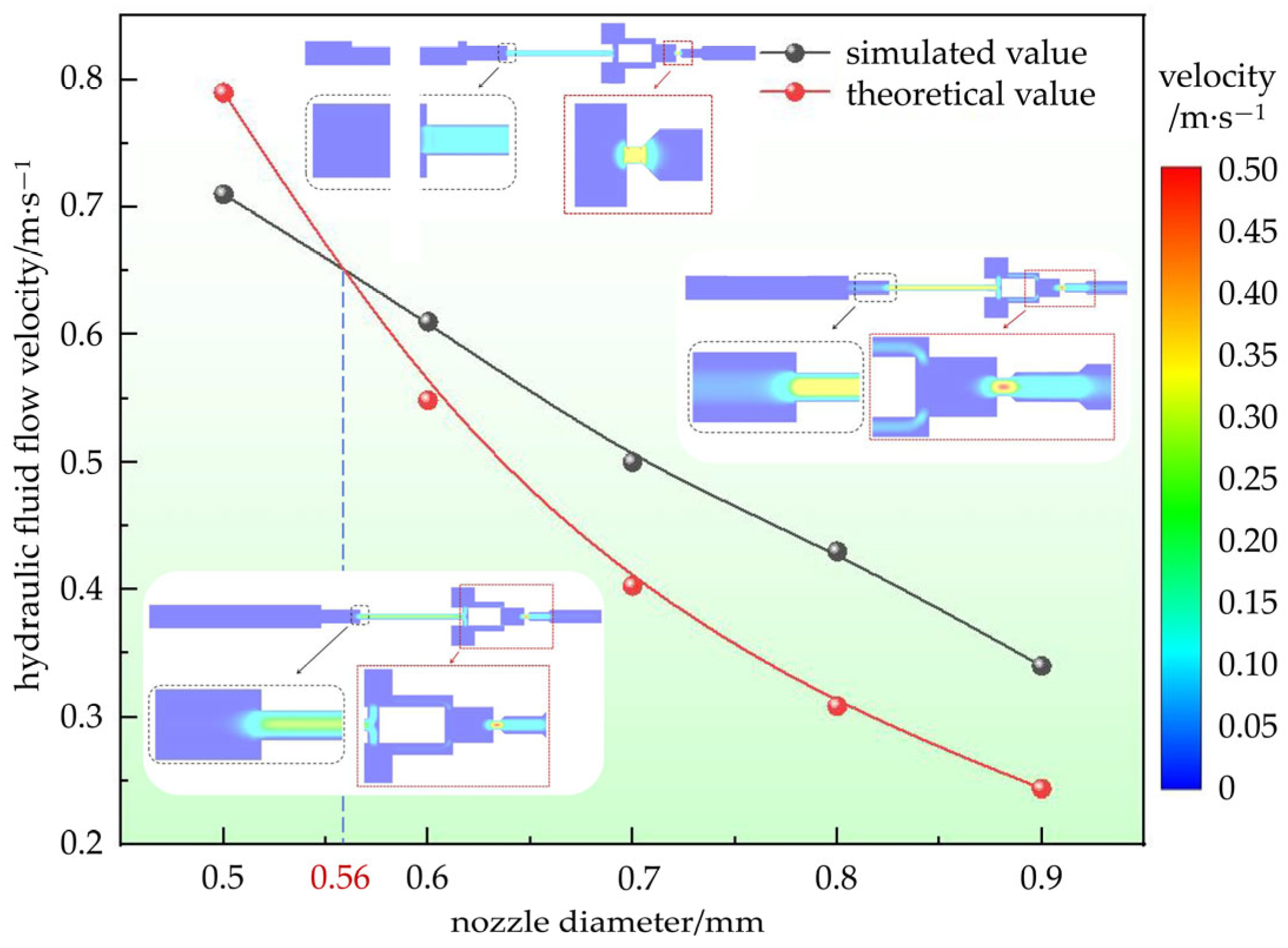
4.3. Optimization Analysis of the Nozzle of the Delay Mechanism
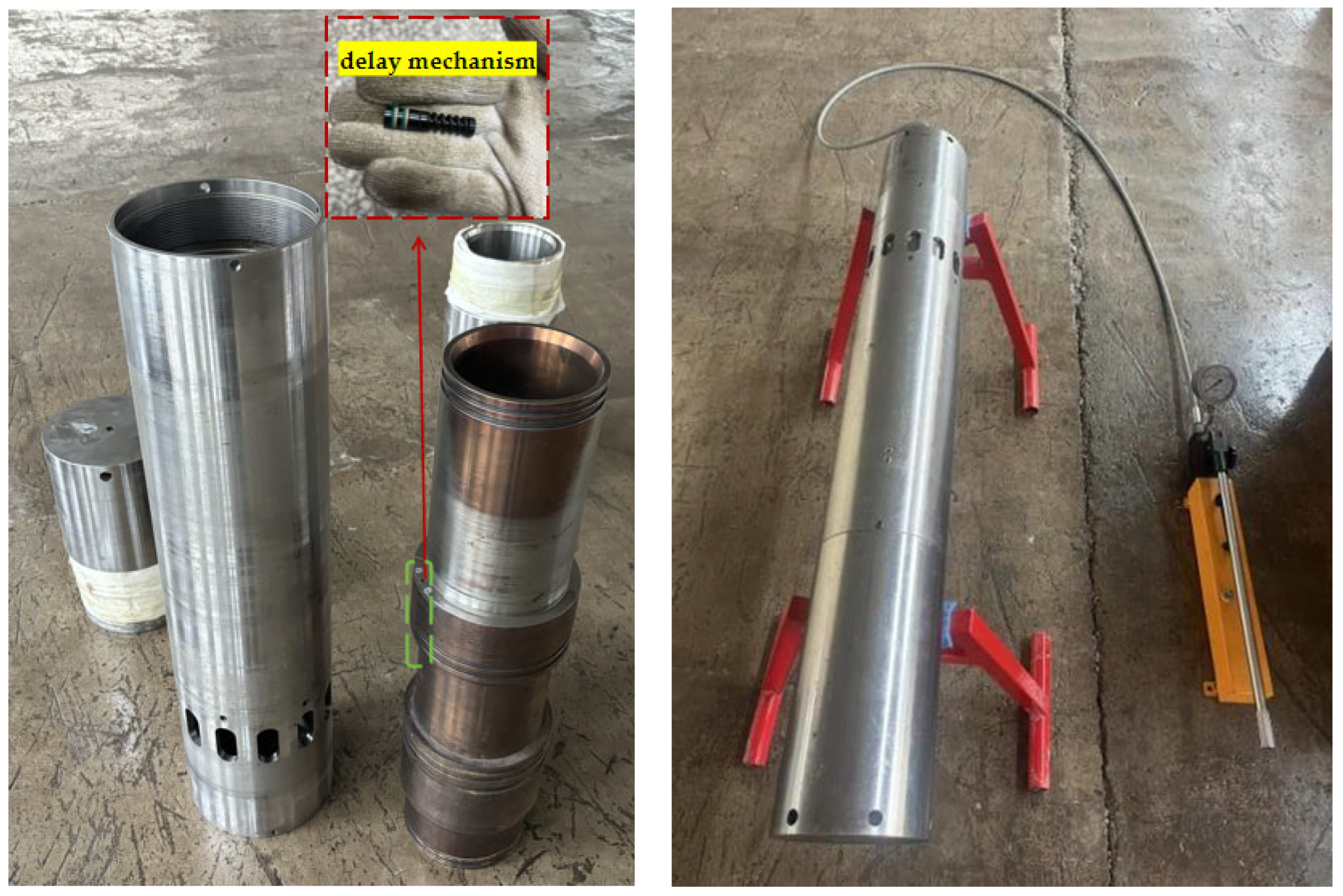
The delayed-opening principle of the toe-end sliding sleeve prototype is due to the presence of a hydraulic oil chamber at the right end of the S2 section. When the pin is sheared off, the delayed opening time is determined by the volume of hydraulic oil in the oil chamber and the nozzle diameter in the delay mechanism. The total volume of the hydraulic oil chamber of the prototype is S2 × l = 5942 × 50 mm2 = 297.1 mL. When all the hydraulic oil flows to the left chamber, the opening of the toe-end sliding sleeve can be delayed by 30 min. In order to obtain the relationship between the nozzle’s equivalent diameter and the hydraulic oil flow rate in the delay mechanism, five nozzle diameters of 0.5 mm, 0.6 mm, 0.7 mm, 0.8 mm and 0.9 mm were selected and the flow field simulation analysis of the delay mechanism control system was carried out. The results are shown in Figure 10.
As can be seen from the figure, the hydraulic oil flow rate decreases with the increase in nozzle diameter, whether in the numerical simulation or the theoretical calculation. Within the research range, when the nozzle diameter in the delay mechanism ranges from 0.5 mm to 0.6 mm, the numerical simulation results are close to the theoretical calculation results.

4.4. Indoor Test

4.4.1. Test Purpose and Process

In order to verify the rationality of the designed delayed-opening toe-end sliding sleeve and the accuracy of numerical simulation, an indoor test prototype was processed in proportion to verify whether the designed prototype can successfully cut off the pin and achieve the preset delay of 30 min. First, wipe the surface of the parts clean, install the sealing ring, and then assemble the parts of the tool, install the nozzle with a diameter of 0.56 mm in the delay mechanism, and install the delay mechanism inside the assembly. Fill the assembly with hydraulic oil and exhaust the air at the same time. Then, fill the manual high-pressure pump with hydraulic oil, and connect the test prototype to the manual pressure pump with a high-pressure pipeline. The test parts and test connection process are shown in Figure 11, respectively.
Before the manual hydraulic pump is used to pressurize, the low pressure is stabilized and the hydraulic pressure indicator is observed. If the indicator remains stable, it means that the internal seal is good and the test can be continued. Continue to pressurize until the test pressure in the wellbore is reached before the sleeve is opened, and use a stopwatch to record the sleeve opening time.

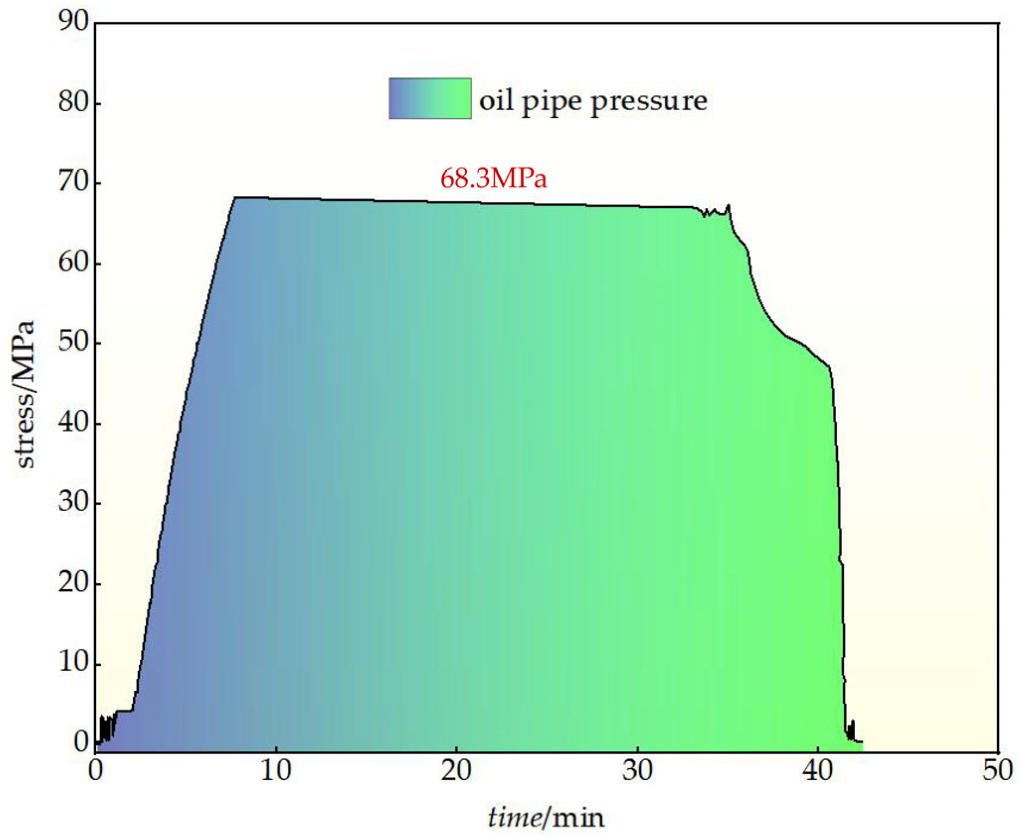
4.4.2. Test Results Analysis

The test recorded the shearing conditions of the M10 pins and the pressure gauge readings when the toe-end sliding sleeve was installed with a single, two (symmetrically arranged up and down), three (equidistantly arranged), four, five, and six shear pins with a delay mechanism, and obtained the test and theoretical calculation results as well as the pin shearing conditions, as shown in Figure 12.
It can be seen from Figure 12a that when the number of pins is less than or equal to five, the opening pressure test value of the toe-end sliding sleeve prototype is approximately equal to the theoretical calculation value, and the relative error value is between 1.64% and 5.72%. The test results prove that the prototype tool conforms to the differential pressure sleeve opening principle; it can be concluded from Figure 12b that when the number of installed pins is 6, the delay mechanism is added and the manual pressure pump pressurization process is 40 min, the toe-end sliding sleeve tool has a maximum opening delay of 28.3 min and the relative error rate with the design theoretical value of 30 min is only 5.67%. This shows that the tool can meet the needs of the full wellbore pressure test, thereby ensuring the integrity of the wellbore. On the other hand, as the length of the manual high-pressure pump pressurization process increases, the delay performance of the toe-end sliding sleeve prototype tool will be reduced, showing a trend of a slow reduction at first and then a rapid reduction. Specifically, when the pressure test process reaches 100 min, the delayed opening time is only 16.3 min, and the relative error value reaches 45.67%, which is quite different from the theoretical value. However, in fact, it only shortens the opening time of the toe-end sliding sleeve and does not affect the actual application of the wellbore pressure test.

4.5. Field Application

During the actual field test, the blind plates at both ends of the full-size prototype and the excess and redundant materials were turned into casing buckle shapes in preparation for connecting the casing strings.
According to the functional characteristics of the newly developed toe-end sliding sleeve, the sliding sleeve is opened by pressurizing the inside of the sliding sleeve and generating thrust on the pressure difference surface of the inner sliding sleeve. At the same time, the sliding sleeve performance field test of the sleeve was carried out in the Gu-xy-Q3 well. By adjusting the shear pressure of the shear nail, the sleeve opening pressure is controlled to be 70 MPa and the test value is 68.3 MPa. The pressure curve is shown in Figure 13.
During the construction process, the toe-end sleeve was pressurized and the pressure test was delayed. No abnormal situation occurred during the pressure relief process, and the tool opened smoothly. By adding a sleeve control valve, the sleeve opening delay time was adjusted to about 30 min. The test showed that the sleeve opening time was 26.4 min, which was basically consistent with the design value. In actual field application, the wellhead pressure test equipment has a fast pressure test process, and the problem of too short a full wellbore pressure test time will not occur.
The toe-end sliding sleeve is used as the first stage of fracturing at the toe of a horizontal well, which can greatly save on-site operation costs and improve operation efficiency. It has important practical significance and can increase the production and transformation of shale oil and gas reservoirs and the efficient development of low-permeability oil and gas reservoirs.

5. Conclusions

(1) When the designed Φ185 mm delayed-opening toe-end sliding sleeve is subjected to an internal pressure of 110 MPa, the maximum stress value generated in the tool is 835.935 MPa, which is less than the allowable stress of the material of 930 MPa; at the same time, the maximum strain value generated in the tool occurs at the position corresponding to the maximum stress value, and its value is 5.5 × 10⁻³, which shows that the numerical simulation is credible.
(2) By analyzing the influence of five different delay mechanism nozzle apertures of 0.5 mm, 0.6 mm, 0.7 mm, 0.8 mm and 0.9 mm on the flow rate of hydraulic oil in the delay mechanism, the delay mechanism nozzle with a diameter of 0.56 mm was used as the indoor test object. When the delay mechanism nozzle diameter is between 0.5 mm and 0.6 mm, the numerical simulation results are close to the theoretical calculation results.
(3) By setting up an indoor test process, it was verified that when the number of pins is less than 6, shear failure can occur and the minimum relative error value is 1.64%; when the number of pins is 6 and the delay mechanism is installed, the longest delay for this kind of delayed-opening toe-end sliding sleeve is 28.3 min.
(4) By setting the displacement parameters of the sleeve control valve, the delayed-opening function of the sleeve can be achieved. Field tests show that a sleeve delay of 30 min meets the design requirements.
(5) The delayed-opening toe-end sliding sleeve used in the construction of long horizontal sections is used as the first stage of fracturing at the toe of a horizontal well. The modular design improves the adaptability of the tool, which can greatly save on-site operation costs, improve operation efficiency and is easy to manufacture and install, reducing replacement costs and improving maintenance efficiency. At the same time, the tool uses a customized design to meet the needs of application in different well conditions, and has important practical significance and can increase the production and transformation of shale oil and gas reservoirs and the efficient development of low-permeability oil and gas reservoirs.

Author Contributions

Conceptualization, W.L. and F.C.; data curation, H.Z.; formal analysis, T.M.; funding acquisition, W.L. and F.C.; methodology, M.C.; project administration, W.L.; resources, F.C.; software, W.N. and M.Z.; supervision, M.C.; writing—original draft, F.C. All authors have read and agreed to the published version of the manuscript.

Funding

This work was supported by the National Natural Science Foundation of China under contract No. 52274005.

Data Availability Statement

The raw data supporting the conclusions of this article will be made available by the authors upon request.

Conflicts of Interest

The author Wei Li is employed by Northeast Petroleum University. The remaining authors declare that the research was conducted in the absence of any commercial or financial relationships that could be construed as potential conflicts of interest.

References

  1. He, H.M.; Huang, Y.Z.; Ren, S.; Liu, L.; Ci, J.F. Multi-stage fracturing technology and its application in horizontal well of tight gas reservoir. Drill. Prod. Technol. 2012, 35, 62–65. (In Chinese) [Google Scholar] [CrossRef]
  2. Wang, J.L.; Yi, W.K. Design of releasable staged fracturing string for cased hole. China Pet. Mach. 2017, 45, 107–110. (In Chinese) [Google Scholar] [CrossRef]
  3. Zhao, M.; Wang, W.J.; Liu, H.B.; Wang, X.Q. Study on completion by coiled-tubing fracturing and cementing sliding sleeves in shale gas wells. Drill. Prod. Technol. 2017, 40, 59–62. (In Chinese) [Google Scholar] [CrossRef]
  4. Dusseault, M.; Mclennan, J.; Jiang, S. Massive malti-stage hydraulic fracturing for oil and gas recovery from low mobility reservoirs in china. Pet. Drill. Tech. 2011, 39, 6–16. (In Chinese) [Google Scholar] [CrossRef]
  5. Yang, T.Y.; Wei, L.; Feng, L.Y.; Ma, L.R.; Zhu, Y.J. Design and test of key tools in horizontal Well toe-end fracturing. Pet. Drill. Tech. 2018, 46, 54–58. (In Chinese) [Google Scholar] [CrossRef]
  6. Wang, J.Y.; Shuai, C.G.; Xu, W.N.; Yi, S.; Zhang, X.F. Analysis and inspirationof toe fracturing sliding sleeve technology. Drill. Prod. Technol. 2023, 46, 57–63. (In Chinese) [Google Scholar] [CrossRef]
  7. Guan, H.L.; Wang, Z.H.; Liu, B.H. The technical states of cementing sliding sleeve for staged fracturing. China Pet. Mach. 2021, 49, 84–92. (In Chinese) [Google Scholar] [CrossRef]
  8. Qin, J.L.; Chen, Z.; Yang, T.Y.; Dai, W.C.; Wu, C.F. Technology of staged fracturing with multi-stage sleeves for horizontal wells in the Ordos Basin. Pet. Drill. Tech. 2015, 43, 7–12. (In Chinese) [Google Scholar] [CrossRef]
  9. Qin, J.L.; Wu, J.H.; Cui, X.J.; Li, F.P.; Zuo, C.Y. Key technology on ball-activated sleeve for open hole staged fracturing. Pet. Drill. Technol. 2014, 42, 52–56. (In Chinese) [Google Scholar] [CrossRef]
  10. Wang, C.Q.; Shuai, C.G.; Wu, H.Q. Application of new cementing sliding sleeve technologies to Zi 203 well. Nat. Gas Explor. Dev. 2018, 41, 102–104. (In Chinese) [Google Scholar] [CrossRef]
  11. Zhu, Y.J.; Liu, X.P.; Wei, L. Research on key technology of time-delayed activation of toe sleeve in horizontal well. Drill. Prod. Technol. 2019, 42, 80–83. (In Chinese) [Google Scholar] [CrossRef]
  12. Shi, Z. Halliburton launches Elect voltage cracking sleeve. Pet. Drill. Tech. 2019, 47, 33. (In Chinese) [Google Scholar]
  13. NOV. i-Opener TD-Toe Sleeve. Available online: https://www.nov.com/-/media/nov/files/about/news/introducing-the-newest-additions-to-our-family-of-multistage-fracturing-toe-sleeves/iopener-td-technical-specifications.pdf (accessed on 19 March 2025).
  14. Packers Plus. Toe-XT Testable Hydraulic Sleeve Enables High Pressure Casing Test and Sleeve Opening below Formation Frac Pressure. Available online: https://www.packersplus.com/en/performances/toe-xt-testable-hydraulic-sleeve-enables-high-pressure-casing-test-and-sleeve-opening-below-formation-frac-pressure (accessed on 19 March 2025).
  15. Packers Plus. Toe-XT Hydraulic Sleeve Successfully Activated After 8 Months. Available online: https://www.packersplus.com/en/performances/toe-xt-hydraulic-sleeve-successfully-activated-after-8-months (accessed on 19 March 2025).
  16. Packers Plus. Packers Plus Toe-XT Hydraulic Sleeve Provides Flexibility for Casing Integrity Test. Available online: https://www.packersplus.com/en/performances/packers-plus-toe-xt-hydraulic-sleeve-provides-flexibility-for-casing-integrity-test (accessed on 19 March 2025).
  17. Guo, Z.H.; Wei, L.; Ma, L.R. Newtype stepless casing sliding sleeve and its application. China Pet. Mach. 2012, 40, 91–94, 99. (In Chinese) [Google Scholar] [CrossRef]
  18. Yuan, F.; Blanton, E.; Inglesfield, J. Single-size-ball interventionless multi-stage stimulation system improves stimulated reservoir volume and eliminates milling requirements: Case studies. In Proceedings of the SPE Russian Oil and Gas Exploration & Production Technical Conference and Exhibition, Moscow, Russia, 14–16 October 2014. [Google Scholar] [CrossRef]
  19. Algadi, O.; Filyukov, R.; Luna, D. Multistage hydraulic fracturing using coiled tubing-activated frac sleeves: Case study from the permian basin. In Proceedings of the SPE Annual Technical Conference and Exhibition, Amsterdam, The Netherlands, 27–29 October 2014. [Google Scholar] [CrossRef]
  20. Bybee, K. Multiple-layer completions for treatment of multilayer reservoirs. J. Pet. Technol. 2008, 60, 80–82. [Google Scholar]
  21. Stegent, N.; Howell, M. Continuous multistage fracture-stimulation completion process in a cemented wellbore. In Proceedings of the SPE Eastern Regional Meeting, Charleston, WV, USA, 23–25 September 2009. [Google Scholar] [CrossRef]
  22. Baumgarten, D.; Bobrosky, D. Multi-stage acid stimulation improves production values in carbonate formations in western Canada. In Proceedings of the SPE Saudi Arabia Section Technical Symposium, Al-Khobar, Saudi Arabia, 9–11 May 2009. [Google Scholar] [CrossRef]
  23. Halliburton. RapidStage®. Multistage Frac Sleeve Systems. Available online: https://www.halliburton.com/en/products/halliburton-rapidstage-multistage-frac-sleeve-systems (accessed on 19 March 2025).
  24. Rytlewski, G.; Lima, J.; Dolan, B. Novel technology replaces perforating and improves efficiency during multiple layer fracturing operations. In Proceedings of the Rocky Mountain Oil & Gas Technology Symposium, Denver, CO, USA, 16–18 April 2007. [Google Scholar] [CrossRef]
  25. Rytlewski, G. Multiple-layer completions for efficient treatment of multilayer reservoirs. In Proceedings of the IADC/SPE Drilling Conference, Orlando, FL, USA, 4–6 March 2008. [Google Scholar] [CrossRef]
  26. Rytlewski, G.L.; Cook, J.M. A study of fracture initiation pressures in cemented cased-hole wells without perforations. In Proceedings of the SPE Gas Technology Symposium, Calgary, AB, Canada, 15–18 May 2006. [Google Scholar] [CrossRef]
  27. Liu, H.L.; Su, H.Y.; Ma, X.Z.; Guan, Z.Y.; Tang, H.; Guo, L.; Lu, W.T. Development and field test of toe end sliding sleeve for cementing. Drill. Prod. Technol. 2024, 47, 120–126. (In Chinese) [Google Scholar] [CrossRef]
  28. Zheng, R.Q. Technical analysis on the application of sliding sleeves at the oil toe of Daqing Gulong shale. Petro-Chem. Equip. 2024, 27, 142–145. (In Chinese) [Google Scholar]
  29. Liu, B. Development and experiment of electronic toe-end frac sliding sleeve. China Pet. Mach. 2024, 52, 103–108. (In Chinese) [Google Scholar] [CrossRef]
  30. Liu, T.; Hou, Z.M.; Hu, S.Q.; Zhao, W.; Pan, M. Development and application of unlimited-stages fracturing sliding sleeve on horizontal well. Oil Field Equip. 2016, 45, 75–77. (In Chinese) [Google Scholar] [CrossRef]
  31. Hu, Y.F.; Tian, Z.L.; Li, J.; Yang, H.L.; Zhang, H.; Ma, H. Optimization design and analysis of pressure differential sliding sleeve. China Pet. Mach. 2018, 46, 61–66. (In Chinese) [Google Scholar] [CrossRef]
  32. Yang, J. Analysis of key technology of test pressure-text toe-end sliding sleeve. J. Jianghan Pet. M Eng. Univ. 2020, 33, 54–56. (In Chinese) [Google Scholar] [CrossRef]
  33. Wei, L. Application analysis and structural improvement of toe-end sliding sleeve based on well conditions. Nat. Gas Ind. 2022, 42, 102–105. (In Chinese) [Google Scholar] [CrossRef]
  34. Zhao, G.M.; Wang, Z.H.; Zhao, M.Q.; Bo, T.T.; An, Q.C.; Zhang, G.H.; Ren, Y. Application of integrated string for casing sliding sleeve fracturing and production. Drill. Prod. Technol. 2023, 46, 162–166. (In Chinese) [Google Scholar] [CrossRef]
  35. Wang, B.; Guo, Y.B.; Tian, X.Y.; Liu, B.; Wei, L.; Wang, D.G. Design of intelligent toe slide sleeve for horizontal well fracturing device. Oil Field Equip. 2021, 50, 52–59. (In Chinese) [Google Scholar] [CrossRef]
  36. Xu, C.Q. Analysis of anomalies and causes of pressure-test aelayed toe initiator valve (TIV) in fuling shale gas field. J. Jianghan Pet. Univ. Staff Work. 2024, 37, 33–35. (In Chinese) [Google Scholar] [CrossRef]
  37. Wang, J.J.; Wang, X.; Liu, J.C.; Wang, S.Q. Calculation and analysis on opening pressure of pressure sliding sleeve. Mech. Eng. 2022, 53–56. Available online: https://qikan.cqvip.com/Qikan/Article/Detail?id=7106970116&from=Qikan_Search_Index (accessed on 19 March 2025). (In Chinese).
  38. Zhao, X.Z.; Jin, F.M.; Chen, C.W.; Jiang, W.Y.; Han, W.Z.; Liu, X.W.; Tang, J.Z.; Xu, J.; Chai, G.Q.; Zhang, S.L.; et al. Technology and result evaluation of well cementing sliding sleeve single-cluster hole fracturing for continental shale oil reservoir. China Pet. Explor. 2024, 29, 136–147. (In Chinese) [Google Scholar] [CrossRef]
  39. Wang, X.X.; Li, W.W.; Xu, Y.T.; Qu, X.M.; Li, W. Research and analysis about application of NCS fracturing sleeve in large-scale fracturing on offshore. Shandong Chem. Ind. 2024, 53, 218–219. (In Chinese) [Google Scholar] [CrossRef]
  40. Liu, D.L.; Chen, Y.P.; Li, A.X.; Guo, L. A new first-stage fracturing process of horizontal well in unconventional oil and gas based on wetshoe cementing. Oil Drill. Prod. Technol. 2023, 45, 85–89. (In Chinese) [Google Scholar] [CrossRef]
  41. Liu, C.Y.; Xia, H.G.; Li, C.P.; Zhang, X. New progress and development suggestions on fracturing tools and technologies. Oil Field Equip. 2022, 51, 66–75. (In Chinese) [Google Scholar] [CrossRef]
  42. Xue, X.B.; Hua, Z.J.; Zhu, X.H.; Liu, H.J.; Zhang, C.C.; Qu, Y.; Shi, C.S.; Cheng, L.F. Sensitivity analysis and optimization of infinite cementing sliding sleeve sealing rubber cylinder parameters. Lubr. Eng. 2025, 50, 129–137. (In Chinese) [Google Scholar] [CrossRef]
  43. Chu, Y.J.; Wen, J.; Li, N.; Liu, S.; Bai, J.Y.; Xiong, L. Research on intelligent completion system of single tubing hydraulic control sliding sleeve. Petrochem. Ind. Technol. 2024, 31, 110–112. (In Chinese) [Google Scholar]
  44. Zhou, B.C. Analysis and measures of abnormal opening of unlimited-stage sliding sleeve in Nanchuan shale gas wells. Pet. Geol. Eng. 2024, 38, 94–99. (In Chinese) [Google Scholar]
Figure 1. Full-size prototype structure diagram. In the figure, S1 is the upper end surface of the inner sliding sleeve; S2 is the annular end surface of the hydraulic oil chamber of the inner sliding sleeve; S3 is the lower end surface of the inner sliding sleeve; l is the distance the inner sliding sleeve moves when the delay mechanism works.
Machines 13 00253 g001
Figure 2. The schematic diagram of the closing and opening states of the delay mechanism.
Machines 13 00253 g002
Figure 3. Grid independent test results.
Machines 13 00253 g003
Figure 4. Boundary condition settings. The pink arrow indicates the magnitude and direction of the hydraulic pressure applied inside the toe-end sliding sleeve, and the blue and yellow triangular arrow indicates the fixed constraint applied by the outer tube of the toe-end sliding sleeve.
Machines 13 00253 g004
Figure 5. Stress cloud diagrams of different states of the full-size prototype.
Machines 13 00253 g005
Figure 6. Strain cloud diagrams of different states of the full-size prototype.
Machines 13 00253 g006
Figure 7. Pin force cloud diagram. where M-M represents the cross section of uniformly arranged pins.
Machines 13 00253 g007
Figure 8. Pin status at different times during pin shearing.
Machines 13 00253 g008
Figure 9. Stress–strain curve (pin shear process).
Machines 13 00253 g009
Figure 10. Comparative results of numerical simulation and experimental values.
Machines 13 00253 g010
Figure 11. Physical drawings of test prototype parts and overall process.
Machines 13 00253 g011
Figure 12. Test results.
Machines 13 00253 g012
Figure 13. Construction curve.
Machines 13 00253 g013
Table 1. Performance comparison of different types of sliding sleeves.
CompanyHalliburtonNOVPackers PlusSchlumberger——
Tool nameElect Sleevei-OpenerToe-XTTAP Fracturing Completion SystemDelayed-opening toe-end sliding sleeve
ApplicationsMulti-productive zone fracturing completionFirst-stage fracsFirst-stage fracsFirst-stage fracsFirst-stage fracs
FeaturesUnlimited number of fracable areasCycle Open i-Open-erOpens at a specific absolute pressureOnly applicable to wellbores above ϕ200 mm and casings of ϕ114.3 mmDelayed opening
Activation methodPitchHydraulicHydraulicInsert rubber plug to activateHydraulic
Sliding sleeve typeElectronic fracturing sleeveMechanical sleeveMechanical sleeveMechanical sleeveMechanical Sleeve
Benefits1. Overcoming the number of fracturing stages
2. Optimizing reservoir channels
3. Coordination of software, hardware and mechanical tools
1. Greater accuracy for activation pressure
2. Debris-tole-rant during activation
3. Compatible with industry-standard wiper plugs
1. Saving time and cost in delivering an effective treatment of the first stage
2. Allows the casing string to be pressure tested a single time before opening
1. The overall pressure resistance of the sliding sleeve reaches 70 MPa and the temperature resistance reaches 160 °C
2. After the fracturing is completed, the darts flow back to the lower part of the upper sliding sleeve ball seat and form a flow channel, which can effectively ensure that the subsequent drainage and production will not be blocked
1. Simple structure, convenient installation, easy manufacturing, suitable for mass production
2. Able to work in harsh environments such as high temperatures and high pressures underground
3. No need to lower the first stage of coiled tubing perforation
Table 2. Toe-end sliding sleeve structural parameters.
Structural ParametersPrototype Total Length L/mmPrototype Diameter D/mmInner Sleeve Upper Section S1/mm2Circular Cross Section S2/mm2Inner Sleeve Lower Section S3/mm2Distance Between Section S1 and Section K l/mm
Numeric129818522,201594220,44950
Disclaimer/Publisher’s Note: The statements, opinions and data contained in all publications are solely those of the individual author(s) and contributor(s) and not of MDPI and/or the editor(s). MDPI and/or the editor(s) disclaim responsibility for any injury to people or property resulting from any ideas, methods, instructions or products referred to in the content.

