Abstract
With the increasing use of exoskeletons to reduce physical strain in industrial applications, precise adaptation to the user’s anthropometry is crucial for effective force transmission and user acceptance. This paper presents a method that compensates for axial misalignment between the human joint and the exoskeleton’s axes of rotation to optimize the anthropometric alignment. It further quantifies the resulting displacement, providing instructional recommendations for manual refinement of the exoskeleton’s initial kinematic configuration. The method thereby represents a first step toward a comprehensive investigation of the initial offset’s influence on an anthropometric fit. The mathematical derivation was described using the rigid shoulder exoskeleton “Lucy”. The validation on increasingly complex mock-ups showed an average calculated error of (SD ) in 2D and (SD ) in 3D, where the errors decreased with smaller initial offsets. A preliminary field study with three participants revealed improved anthropometric alignment but indicated limitations in the exoskeleton’s structural adjustment possibilities, highlighting the need for further modifications. Building on these findings, subsequent studies will involve further investigation of factors such as the migration of the instantaneous center of rotation during motion, soft tissue deformations, and greater population diversity.
1. Introduction
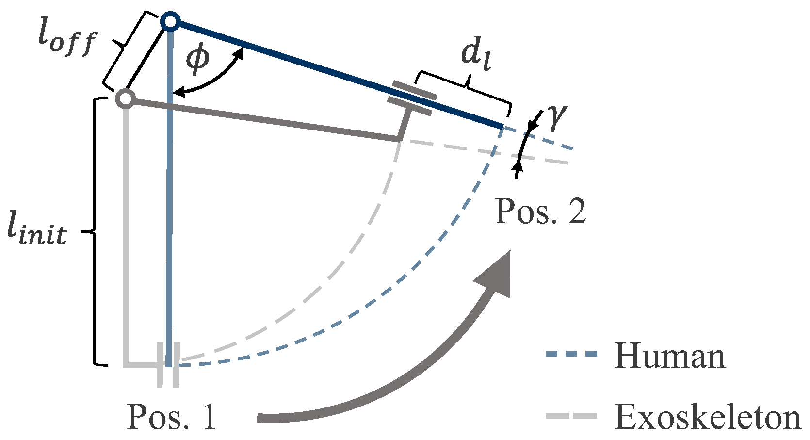
Modern workplaces are increasingly characterized by automation and digitization [1]. However, for the foreseeable future, human workers remain an essential part of modern workplaces [1,2], as their flexibility and learnability [3] address a corresponding trend of customization and individualization [4]. As a result, jobs are dominated by physically demanding tasks or restrictive postures [5,6], which leads to increased musculoskeletal disorders and related work absences [5,7]. Consequently, different approaches are being investigated to support workers and reduce physical strain [2], including industrial exoskeletons [8,9]. Industrial exoskeletons are systems worn on the human body and are designed to reduce physical strain [3,10,11] by shifting loads from areas of the body that are particularly stressed to more load-bearing regions [12]. Depending on the choice of actuation, industrial exoskeletons offer different possibilities for adjusting support to changing requirements during use [13]. However, due to the direct interaction between the exoskeleton and the user, precise alignment of the exoskeletal and human joint axes is critical for mapping the human range of motion (ROM) and ensuring both safety and comfort [14]. As shown in Figure 1, even small misalignments can lead to significant deviations that can compromise functionality.
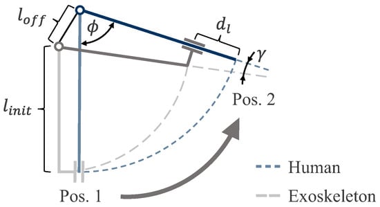
Figure 1.
Relationship between the spatial misalignment , initial length , relative axial displacement , and relative angle during rotation at the specific angle between the two rotation axes at a specific point in time (adapted from [14]).
1.1. Anthropometric Adaptation
Developers are well aware of this issue and consider individual body shapes and sizes during the design process. The solutions differ regarding the kinematic properties of the exoskeletons, which can be divided into soft and rigid systems [15]. Both approaches aim to balance usability and functionality; however, each poses unique challenges regarding an anthropometric fit.
Soft exoskeletons are designed to enhance adaptability and user comfort by utilizing textile elements that wrap around a person’s body [15]. An anthropometric fit can be achieved by providing different exoskeleton sizes comparable with clothing sizes (e.g., Auxivo LiftSuit [16], Morita Rakunie [17]). Fine-tuning can be achieved using straps or belt systems [18,19]. Due to the soft nature of these systems, they cannot transmit compressive, tangential forces through the exoskeleton’s textile structure [20]. As a result, rigid, pressure-resistant, and inflexible components are necessary for tasks requiring significant force transmission.
Rigid exoskeletons, while capable of transmitting forces effectively, must overcome the challenge of maintaining sufficient freedom of movement. Commonly, two approaches are taken: distant-body and near-body structures [21]. While distant-body structures generously bypass human joints (e.g., Auxivo Carrysuit [22], SUITX IX SHOULDER AIR [23], Lockheed Martin FORTIS [24]), near-body structures attempt to replicate the human degrees of freedom (DOFs) as accurately as possible (e.g., SUITX IX BACK [25], Levitate Airframe [26], Comau MATE-XT [27]). Due to their proximity to the body, near-body structures require precise alignment with the user’s joints to preserve a natural ROM [28]. Misalignment leads to angular and axial displacement during rotation (Figure 1, [14]), causing unwanted relative motion between the exoskeleton and the user. This results in undesirable side effects [29], such as friction at the interface, a limited ROM, pressure points, compromised comfort [28,30], and potentially ineffective support or harmful effects [31,32,33]. Ensuring concentric overlap between the user’s joint axes and the exoskeleton’s axes is therefore critical [30,31], yet technically challenging due to the complexity of the movement dynamics of human joints [14,29]. Human joints often do not rotate around a fixed axis [34]; instead, their center of rotation (COR) can shift dynamically during movement [29], which can be observed in joints, such as the knee or shoulder [35,36].
1.2. Self-Aligning Joints
One approach to handling misalignment is to implement self-aligning joints that use a movable linkage system to decouple forces and torques during transmission [37]. This design exploits the reaction forces caused by axis misalignments to dynamically adjust the position of the exoskeleton’s axes to the natural movements of the user [20]. The system compensates until a so-called “zero force position” is reached [38], effectively eliminating unwanted reaction forces, and thus, significantly reducing the strain on the user. However, the consequent provision of support as torques requires an additional connecting point (physical interface); otherwise, a joint translation will occur [38]. Combined with the complexity of the moving linkage, this additional interface results in a higher number of components, increasing the complexity of the overall system. For this reason, some approaches introduce mechanisms to compensate for joint misalignments [14,34]. For example, an additional DOF in the form of a translational bearing could offer freedom of movement to compensate for misalignment (e.g., Comau MATE-XT [27]). Although this DOF effectively enables axial displacement, it does not provide feedback on the extent of the misalignment. As a result, no potential adjustments can be derived to improve the overall alignment of the exoskeleton on the user’s body. In addition, it does not provide valuable data for operators [29] or developers to refine the design or optimize the fit of a potential successor.
In order to obtain such information, the instantaneous COR of the human joint must be known [29]. Traditionally, techniques such as optical motion tracking [39], electromagnetic tracking [40], inertia measurement units (IMUs) [41], and ultrasound imaging [42] have been used to determine human joints’ CORs. However, these methods are resource-intensive and require laboratory facilities and specialized equipment, making them impractical for industrial applications.
1.3. Research Gap
A promising direction for future innovation could be the integration of COR estimation into the mechanisms used to compensate for joint misalignment. Such systems could dynamically monitor joint misalignment and derive adjustment recommendations, potentially reducing the need for expert assistance and ensuring the correct use and supporting user training. Therefore, in addition to functional compensation, the approach could improve the precise alignment of rotational axes between the human and exoskeleton and, ultimately, the user-friendliness and performance.
In this context, this work represents the first step toward a comprehensive investigation of the influence of an initial offset on the anthropometric fit. A novel, practical method is presented that actively compensates for axial misalignment and quantifies the resulting displacement, providing direct feedback for manual refinement of the exoskeleton’s initial kinematic configuration. Using the shoulder exoskeleton “Lucy” [43] as a research platform, a pilot study demonstrates the feasibility of this method under controlled conditions. It should be noted that the presented study focused on static spatial misalignment as a first step, while dynamic analyses and the influence of soft tissues will be addressed in future work.
2. Mathematical Foundation
Building on Grübler’s equation (three links, two rotational DOFs) and drawing on misalignment compensation strategies from the literature [14,28], the required DOFs for the exoskeleton to align with the human shoulder were therefore realized using a revolute–revolute–prismatic (RRP) kinematic chain. This approach builds upon both the simplification commonly used in biomechanics, where the complex joint group of the shoulder joint and shoulder girdle is idealized as an ideal spherical joint with three rotational DOFs [29] and the existing exoskeleton kinematic structure featuring two intersecting axes [43]. Since the two intersecting axes already exist in the exoskeleton design [43], an additional prismatic DOF was introduced to accommodate the axial displacement . By modeling this offset during rotation as an envelope, which can be tracked during the fitting process, the instantaneous center of rotation (COR) of the human shoulder can be estimated.
Following this approach and to simplify the analysis, it was assumed that there is a fixed contact point between the exoskeleton interface and the human body. Displacements within the skin and subcutaneous tissue were not considered at this first step to further reduce the interaction’s high complexity. Also, minor angular deviations () were assumed to be absorbed by the soft tissue, and thus, do not impact function, as indicated by prior studies on human–exoskeleton interaction [31]. However, it should be noted that angular misalignments can lead to a loss of comfort during interaction [29,33]. Also, simplifying these influences leads to inaccuracies, the effects of which on actual measurements will be examined more closely in a subsequent study. By making these simplifications, the translational displacement remained the primary factor of interest, and thus, the focus of this study (Figure 1).
2.1. Consideration of a 2D Plane
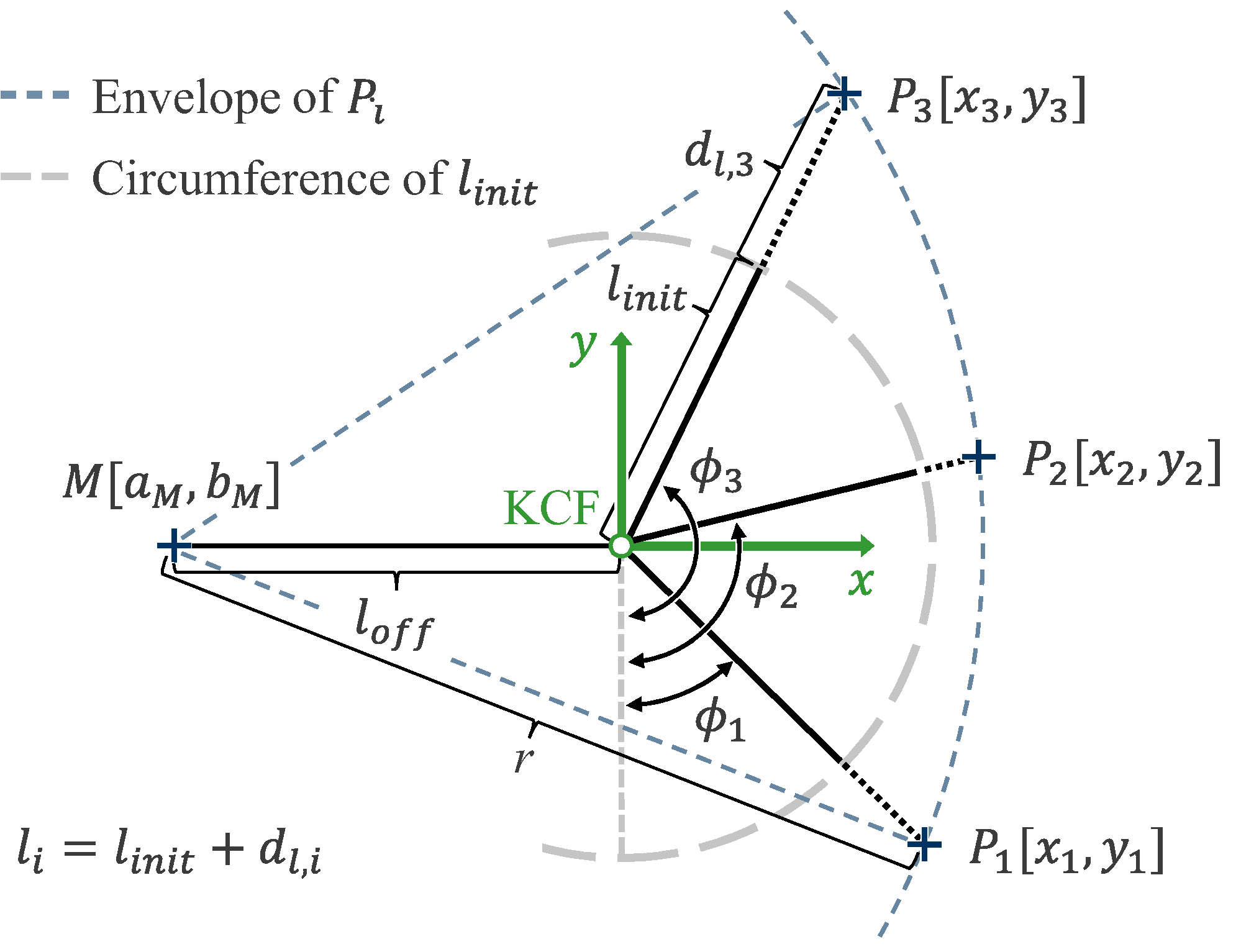
The misalignment was first examined in a 2D plane to identify when and how different factors affected the results. Here, the general equation of a circle (1) is built upon. It describes the relationship between three points on the circumference of the circle and its center , given a fixed radius r (Figure 2):
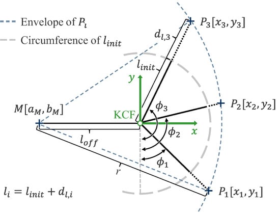
Figure 2.
Determination of the center of rotation (COR) M in the kinematic coordinate frame (KCF) by measuring the user–exoskeleton contact points on the circumference, which can be described through the angles and relative distances .
In the context of the exoskeleton, the relative distance —comprising the initial length (distance to the interface’s initial position) and the compensated relative axial displacement —together with the rotational DOF (the angle of rotation), is measured to derive the polar coordinates of the user–exoskeleton contact points . These polar coordinates are then transformed into Cartesian coordinates for further analysis. These points are expressed within the exoskeleton’s kinematic coordinate frame (KCF), which is centered at the intersection of the exoskeleton’s axes of rotation.
Building on the assumption that the initial user–exoskeleton contact point P remains fixed, the radius r, defined as the distance between the human COR M and the contact point P, was considered constant. This assumption, along with the assumed momentary stationarity of the axes (resulting in a constant , allows the coordinates and of the human COR M to be calculated by solving the system of equations derived from the measured contact points . Essentially, it is possible to deduce the location of the human joint’s COR M directly from the positions of the contact points P.
The resulting vector, which describes the position of the COR M in the KCF, thus quantifies the misalignment between the human COR and the origin of the exoskeleton’s KCF reference frame. By transforming this vector along the adjustment axes of the exoskeleton structure through a transformation matrix, both the position of the COR and the distance from the KCF origin are expressed within the exoskeleton kinematic structure’s adjustment possibilities. This allows for the necessary corrections to be calculated as actionable instructions. Manually adjusting the kinematic structure according to the instructions aligns the exoskeleton’s axes with the user’s limb’s COR, effectively minimizing the misalignment. This refining procedure can be repeated if necessary, leading to an enhancement of the overall alignment, and thus, to an improvement in fit; comfort; and, subsequently, system functionality.
2.2. Calculations in 3D Space
Based on (1), a further dimension was considered to describe the misalignment in three dimensions. This additional rotational DOF describes a spherical surface according to the extended circular equation in parameter form (2):
Following the approach in two dimensions, the COR can be calculated in the KCF using four measured points . These points can be described using the spherical coordinates . The subsequent procedure is analogous to the approach in two dimensions.
Building on these considerations, it becomes evident that the calculations of the spatial misalignment of the human axes COR in both 2D and 3D are based on points on the circumference (2D) or spherical surface (3D). Therefore, the next step involves determining the coordinates of the measured points . This requires the implementation of specific sensors and structural modifications to the exoskeleton.
3. Practical Implementation
The method’s practical implementation and proof of concept were demonstrated using the example of the rigid active shoulder exoskeleton “Lucy” [43]. This exoskeleton, designed for industrial use cases, supports tasks performed at and above head level by providing supportive torque to the shoulder joint. To enable the human shoulder joint’s natural motion and map it with the exoskeleton’s kinematic structure, its rotational axes are aligned with the shoulder’s transverse axis (rotational DOF I) and longitudinal axis (rotational DOF ). In addition, its kinematic structure allows for manual adjustment of the rotation axes and alignment of the exoskeleton interface with the human’s upper arms [13]. This enables manual anthropometric adaptation, either by the user or an expert.
3.1. Implemented Sensors and Required Modifications
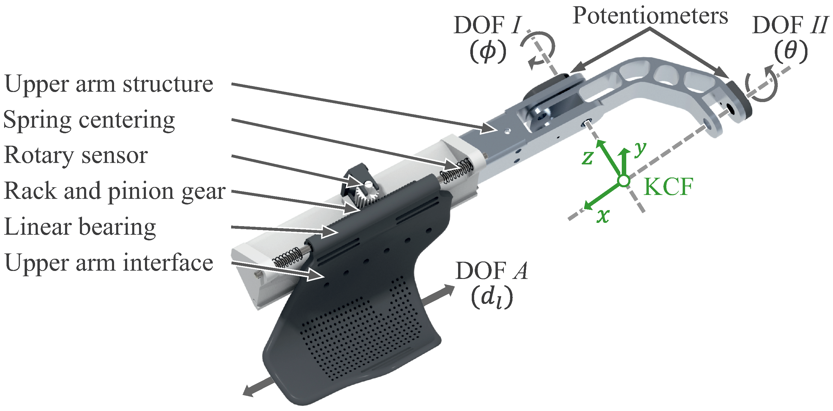
The exemplarily used exoskeleton is equipped with various sensors, including potentiometers on the rotation axes I and (Figure 3). These potentiometers measure the angles (DOF I) and (DOF ) of the exoskeleton’s upper arm kinematic structure, which is coupled to the user’s upper arm through an interface. This setup allows for direct angle measurement without the need for additional structural or sensory modifications. However, to compensate for axis misalignment and quantify the relative axial displacement, the existing interface design [43] was modified to implement a translational DOF A, as introduced in Section 2. This DOF A permits an intended relative displacement by using a linear bearing with minimal friction, simultaneously limiting unwanted relative motion between the exoskeleton’s interface and the user. The resulting relative displacement (DOF A) can be measured using an appropriate sensor setup. To simplify the subsequent calculations, the contact is idealized and regarded as stationary based on the abovementioned assumptions. As the length to the interface’s initial position is predetermined by design and therefore known, the length to the current interface’s position can be determined using the measured displacement .
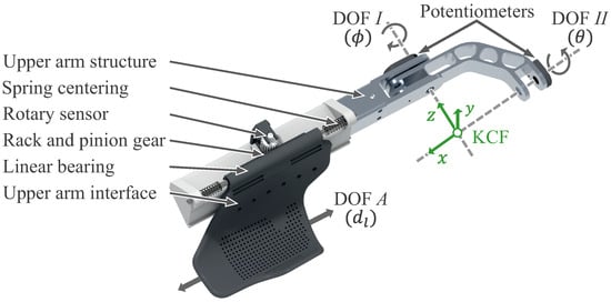
Figure 3.
CAD model of the exoskeleton’s right upper arm structure with a modified interface linkage, a rotary sensor with a rack and pinion gear, rotational joints (DOF I and ), and a new translational joint (DOF A) introduced to measure the displacement .
3.2. Constructive Adaptations
Building on the previous explanations, the required design modifications relate to the interface and its linkage to the exoskeleton’s upper arm mechanical components (Figure 3), whereas the overall mechanical structure remains unaltered. In addition, the linear bearing is accompanied by a physical centering system of the interface using springs. These springs are intended to support the donning of the exoskeleton by centering and stabilizing the interface. The relative axial displacement is indirectly measured via a rack and pinion gear and a rotary potentiometer.
4. Experimental Validation
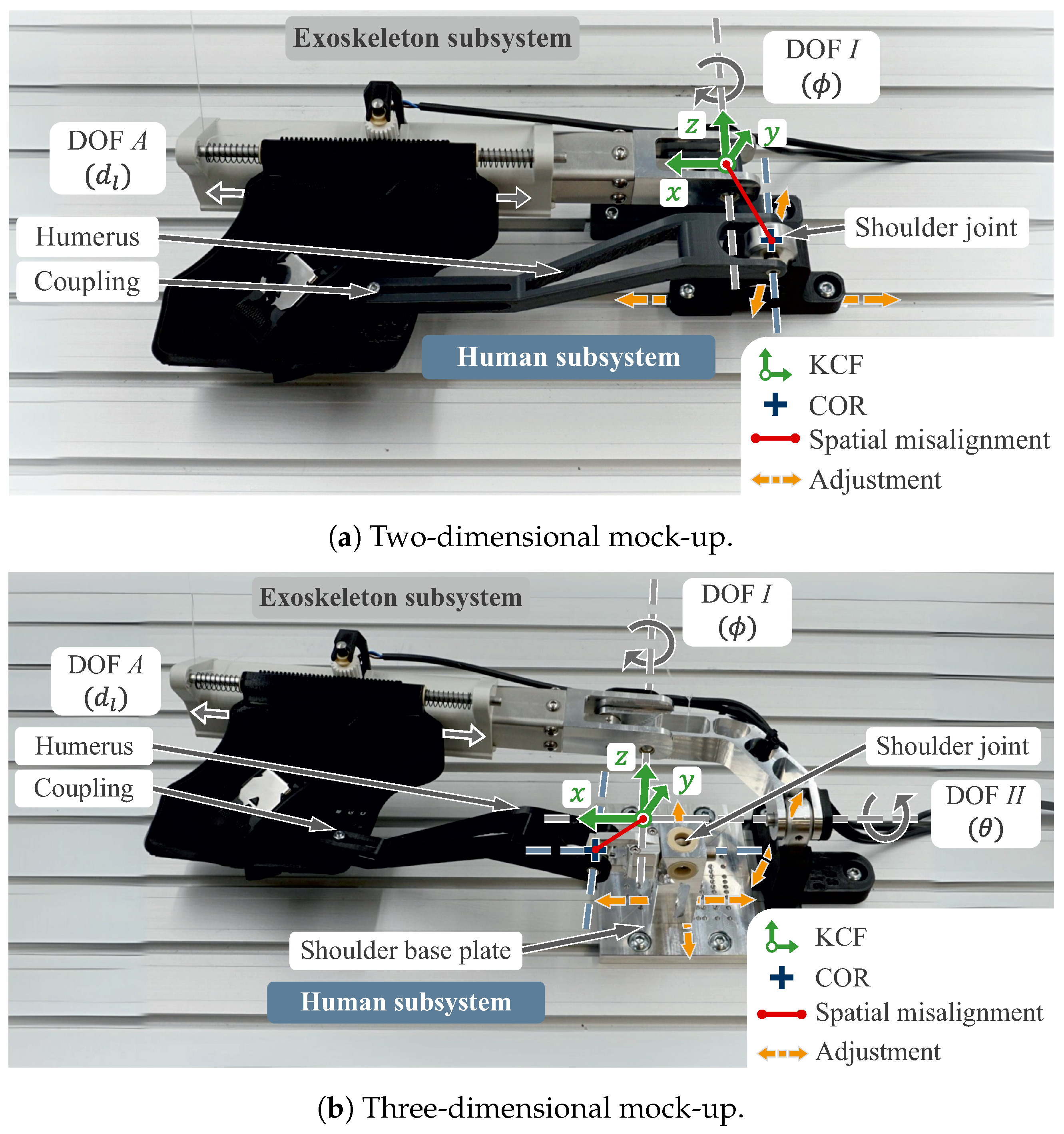
Using mock-ups (Figure 4) to model the simplified human–exoskeleton interaction allowed for experiments under reproducible and defined conditions. This was a significant advantage over field evaluations, especially in real human–exoskeleton interaction. The main goal of these experiments was to evaluate how accurately the setup could measure the displacement and determine the COR over a predefined range of axis misalignments while also identifying uncertainties, such as sensor inaccuracies. Similar to the presented mathematical foundation (Section 2), validation was performed in two successive steps to increase the complexity of the mock-up.
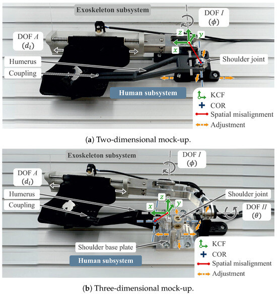
Figure 4.
Presentation of the mock-ups to calculate the spatial misalignment, with the subsystems exoskeleton (interface and mechanical structure) within the zero-plane (angles equal zero) and human shoulder (revolute (2D) or universal joint (3D) and humerus) rigidly connected.
4.1. Mock-Up Introductions
The first validation step used a mock-up in the 2D plane (Figure 4a). The mock-up consisted of two subsystems that formed a kinematic chain. On one side was the human subsystem: a simplified representation of the human shoulder joint with a fixed shoulder socket and a movable upper arm (humerus). This subsystem was rigidly linked to the exoskeleton subsystem and its interface via the humerus. Conversely, the exoskeleton subsystem comprised the associated upper arm mechanical structure and the upper arm interface on a linear bearing.
The simplified structure of the 2D mock-up modeled a single axis of rotation in both subsystems, represented by two revolute joints. The human subsystem’s axial adjustability resulted in a configuration that represented the abstract mathematical model (Figure 2). By adjusting the human subsystem’s connection to the mock-up’s base plate in height and linear position, different planar misalignments () could be predefined between the subsystems.
Building on the 2D mock-up, the second validation step included the third dimension (Figure 4b). The goal was to validate in a context close to the actual application while keeping the advantages of controlled boundary conditions. Considering an additional rotational axis (DOF ), the mechanical structure of the existing shoulder was used to model the exoskeleton, including the second revolute joint. In contrast, the revolute joint of the human subsystem was upgraded to a universal joint. This was intended to ensure that the human subsystem’s shoulder joint reproduced the entire ROM of the exoskeleton kinematic structure while minimizing clearance. The exoskeleton subsystem was connected to the mock-up’s base plate to allow for height adjustments only, while the human subsystem’s adjustable shoulder joint allowed for varying alignments along the shoulder base plate’s axes. This controlled positioning predefined the spatial misalignment between the two axes of rotation and their respective subsystems, which induced relative axial displacement during movement.
4.2. Procedure
Validation for both steps involved manually rotating both subsystems (DOF I in 2D and DOF I and in 3D) at moderate velocities and measuring the relative axial displacement and the corresponding angles for different points on the idealized circumference (in 2D) or spherical surface (in 3D). In order to accurately calculate the axis misalignment in all spatial directions, specific orientations needed to be adopted in the model’s mechanics. The relative displacement could only be fully recorded if the mock-up was rotated within the plane of the misalignment, i.e., its axis of rotation intersected the plane of misalignment orthogonally, which was why the mock-up was rotated within the entire angular range (both DOFs). This ensured that the spatial misalignment induced measurable changes in the axial length, which allowed for full identification of predefined misalignments in all planes. The X-Z plane of the exoskeleton kinematic structure was defined as the zero plane (reference plane). Accordingly, angles equaled zero when the axes of the exoskeleton kinematic structure were in this horizontal plane.
During the initial testing, slight baseline noise in the sensors’ angular data required interpolating the expected geometric shape (using a circle [44] or sphere) through the measured points , which provided an overall cleaner envelope for calculating the COR M. Therefore, multiple measurement points were recorded and interpolated throughout a small angular range, which helped to filter outliers effectively, and thus, further improve the accuracy. Subsequently, building on these measured points, the position of the COR M and the vector of the spatial misalignment within the KCF were calculated.
Direct comparison between predefined and calculated spatial misalignment was performed to evaluate the method’s overall accuracy, thereby using error as the key metric. The error was defined as the Euclidean distance between the predefined misalignment (preset position of the shoulder’s COR M) and the calculated position of the COR M. Repeatability was assessed by conducting measurements over different runs with identical predefined misalignments under consistent conditions.
For the 2D mock-up, initial presets included step sizes of ±0, 2, 4, 8, 15, and in the X-direction and ±0, 2, 4, and in the Y-direction. The steps were clustered around zero to investigate precise fitting and expand with distance for more significant deviations. In 3D, the increased number of measurements necessitated reducing the number of step sizes to ±, 7, 16, and in the X-direction; ±0, 7, 16, and in the Z-direction; and 0 and in the Y-direction, while maintaining proportional scaling. By testing combinations of these presets, a comprehensive “error space” was generated, which validated the method’s precision across different spatial misalignments.
It needs to be noted that the manual setup introduced minor variations to the position of predefined misalignments due to inherent limitations. To ensure reliable reference values of the preset position for analysis, the mock-up’s shoulder COR position (predefined misalignment) was carefully determined using calibration equipment.
5. Findings
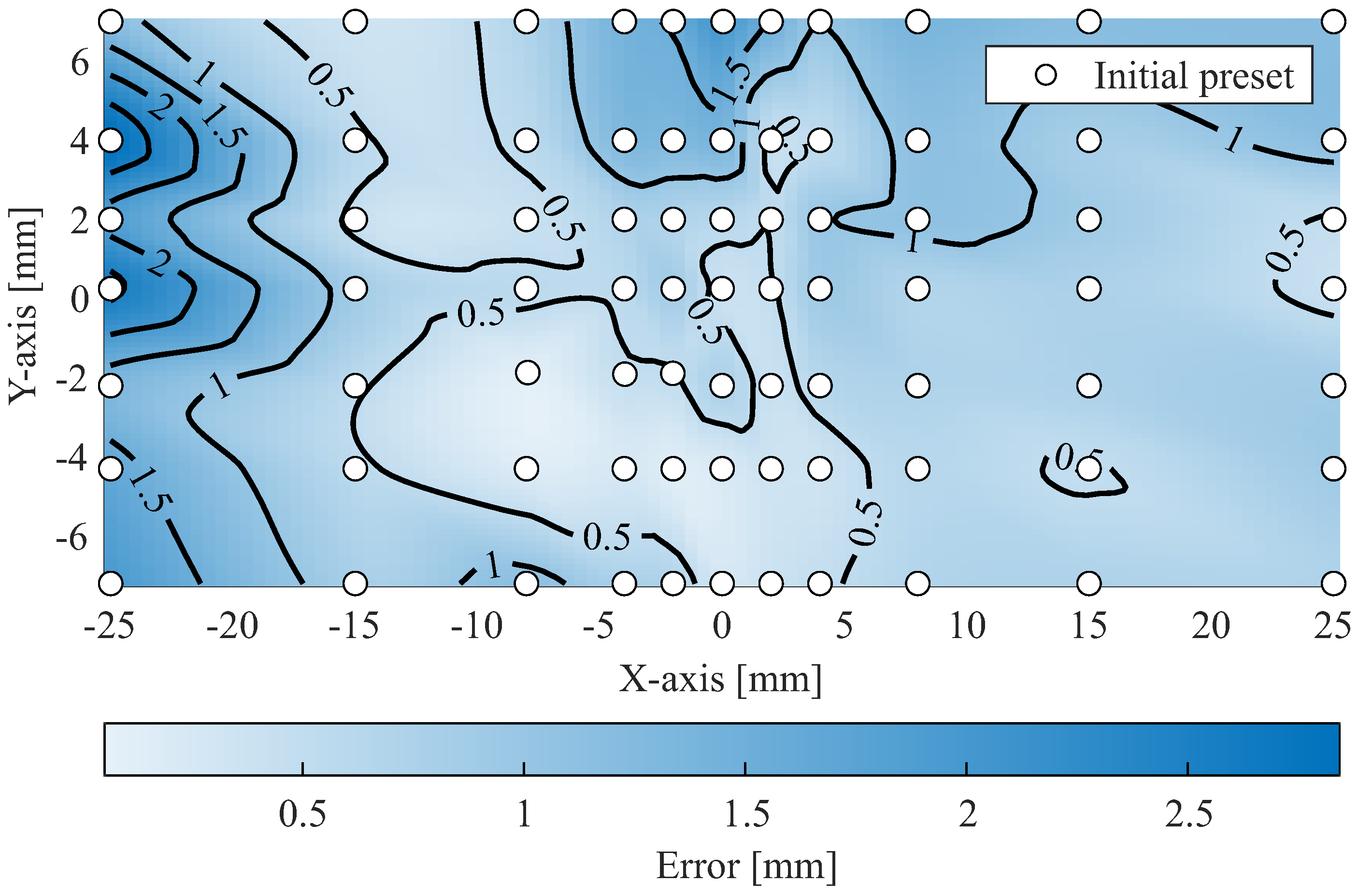
The comparison of predefined and calculated spatial misalignment of the COR on the 2D mock-up (Figure 5), analyzed and plotted using MATLAB (R2023a), showed an average error of , with a standard deviation of , based on measurements taken in three repetitions for each predefined misalignment preset. As more significant predefined misalignments were tested, the variance in the calculated misalignment increased. This rise could be attributed to cumulative inaccuracies, such as rack and pinion gear backlash and sensor noise, as well as potential influences from minor angular deviations (). The initial preset [, ] supported this assumption: no displacement occurred due to the absence of axis misalignment. Here, only mechanical play within the exoskeleton structure and sensor inaccuracies contributed to an observed spatial error of with a standard deviation of .
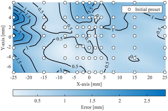
Figure 5.
Two-dimensional mock-up: calculated error of the measurements across the “error space”, with an average of mm and standard deviation of mm.
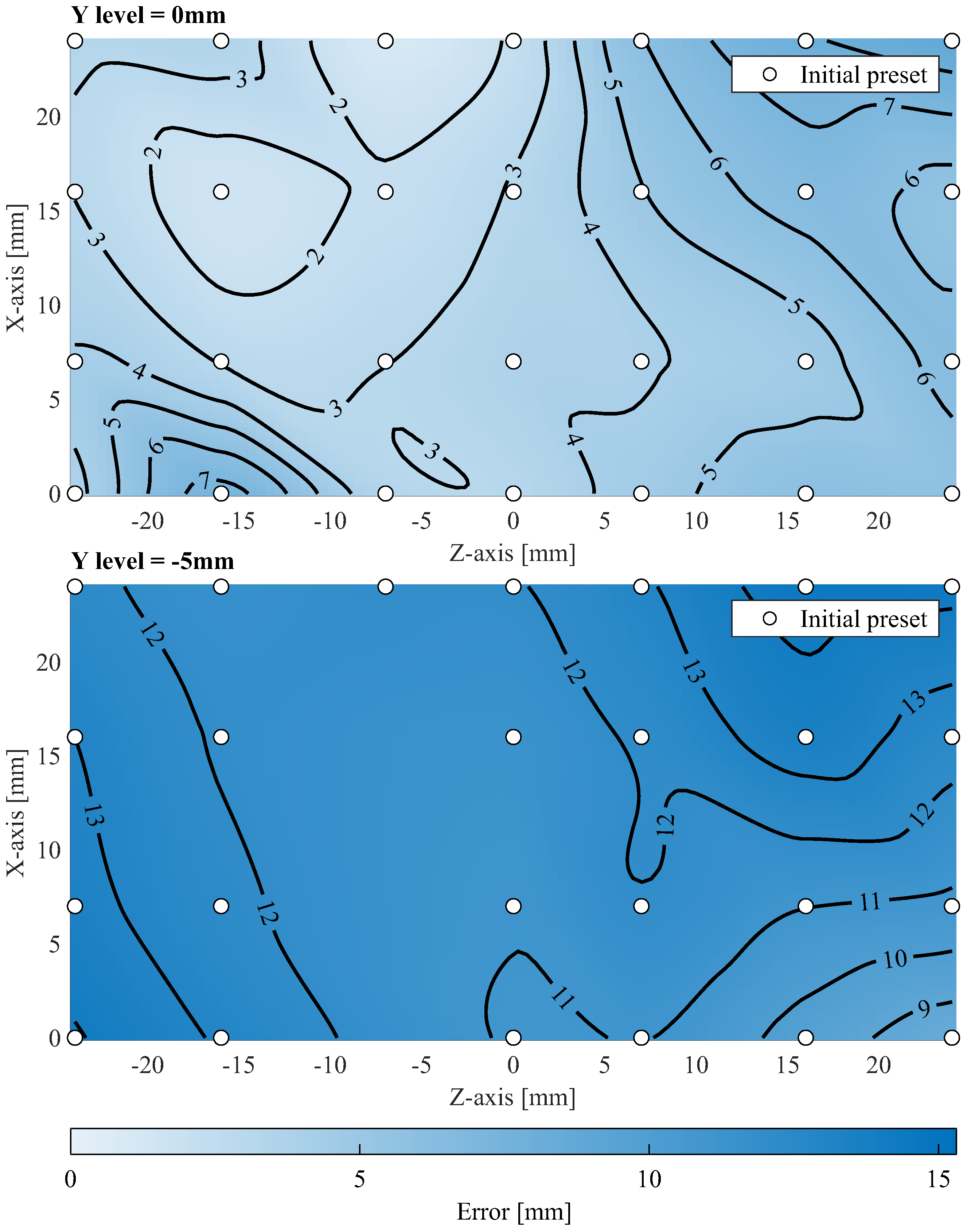
Building on these results, the 3D mock-up advanced the analysis by calculating the spatial misalignment of a measured point cloud on an idealized spherical surface. The measurements (Figure 6), analyzed and plotted using MATLAB (R2023a), yielded an average error of , with a standard deviation of , based on measurements. As with the 2D mock-up, increased predefined misalignments led to higher variance in the calculated misalignment. However, the 3D mock-up showed a higher standard deviation, which reflected the increased challenges posed by its greater structural complexity. This complexity directly impacted the repeatability and revealed limitations in the validation process.
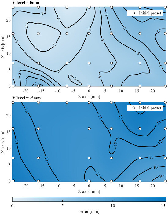
Figure 6.
Three-dimensional mock-up: calculated error for the Y levels [0, −5] and initial presets across the measured “error space”, with an average of mm and standard deviation of mm.
The mock-ups were designed for reproducibility, but complete elimination of inaccuracies was not possible. The increased number of components and tolerances in the joint structures continued through the kinematic chain and contributed to cumulative inaccuracies. Noticeable as a slight rotational backlash, they could cause deviations in the millimeter range for the measured points , which led to more significant errors in the calculated position of the COR. Although the accuracy achieved is considered sufficient for an initial validation, it is essential to recognize that these inaccuracies may affect the practical applicability. The method proved to be robust under controlled conditions, but its performance under real-world conditions still needs to be evaluated. Further validation testing is required to systematically address these cumulative inaccuracies and assess the practical feasibility.
6. Use in Application
Based on the results of the mock-up tests, a first feasibility study was carried out to test the practicability of the presented approach. The aim of this study was to verify the basic functionality and to perform an initial validation in an actual application situation.
6.1. Study Procedure
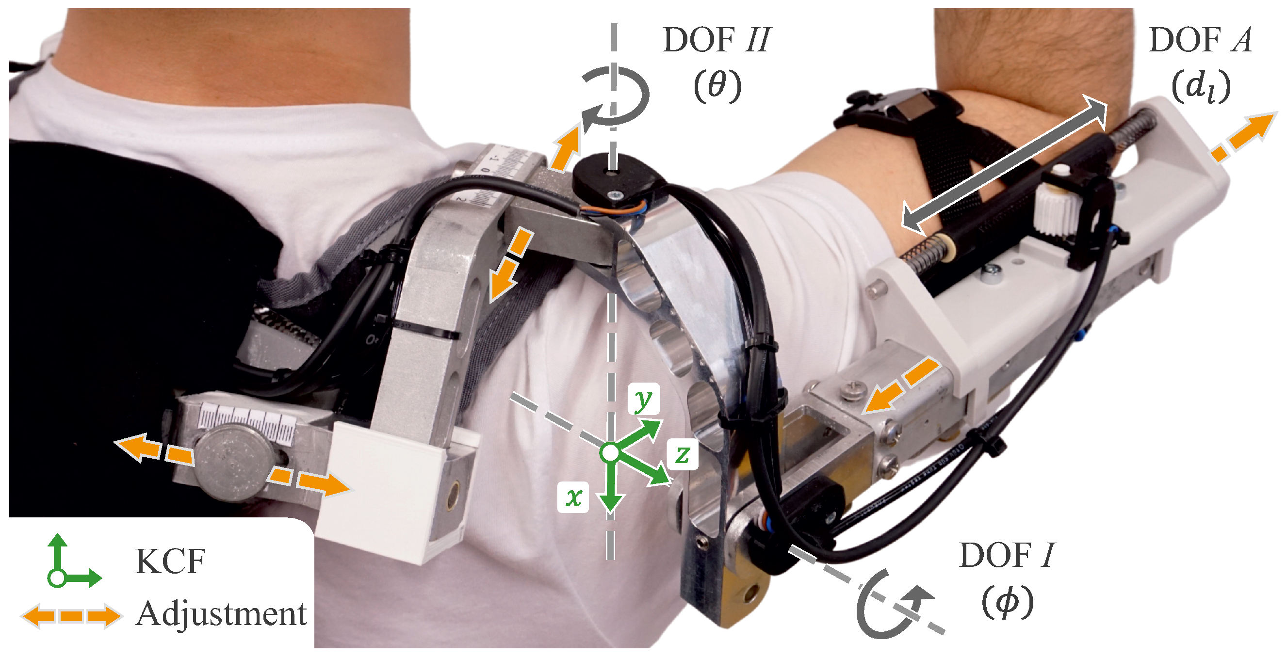
For application with the active shoulder exoskeleton “Lucy”, the adapted interface was implemented in the exoskeleton (Figure 7). A preliminary study was conducted with three male participants (age: , height: , weight: ). While this sample presents limited anthropometric diversity, it was selected to ensure consistency in the initial validation tests. The sample size of three participants was selected to verify the general methodology and to identify potential challenges in the alignment process.
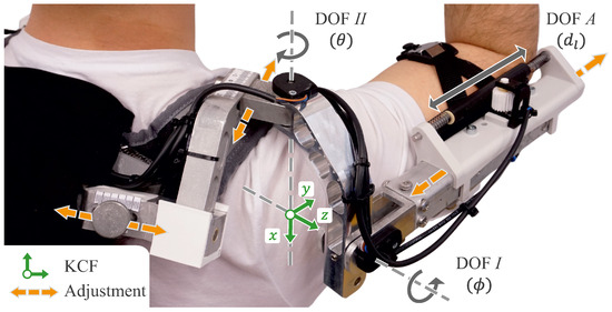
Figure 7.
Shoulder exoskeleton “Lucy” with the modified upper arm interface and centered mechanical structure.
This study aimed to evaluate the method in a two-trial approach. In the first trial, to obtain a constant baseline, the mechanical kinematic structure’s adjustment range of the exoskeleton [13] was centered for all axes (no anthropomorphic adaptation). Participants were instructed to maintain an upright and steady posture to minimize the influence of body movement. As part of the initialization phase, the interface was tightly strapped to the participant’s upper arm, and its position was marked to ensure that the system stayed in place during the trials. This approach was taken to ensure a tight connection between the interface and the upper arm, following the assumption of a fixed contact point between the human and the exoskeleton. Then, the length was measured, and the angular offset of the rack and pinion gear potentiometer () was set to zero as part of the initial calibration.
Then, as part of the first trial, each participant moved their stretched arm in a circular motion defined by markers at comparable speeds using a metronome to ensure consistency between the measurements. The markers were distributed in a spherical sector to allow for the mapping of a comparable large area of the shoulder’s ROM. The COR M was then calculated based on the measured data, following the approach of the 3D mock-up. The calculated displacement and derived adjustment recommendations provided actional instructions to reposition the exoskeleton’s kinematic structure. These adjustments were then performed manually using the attached scales (Figure 7).
The procedure of the first trial was then repeated for the second trial by measuring the misalignment and calculating the COR M again. The accuracy of the performed kinematic adjustments was assessed by comparing the calculated initial COR (first trial) and the calculated COR of the adjusted kinematic structure (second trial). The two trials were performed consecutively without removing the exoskeleton in between to prevent unintended changes or alter the exoskeleton’s position.
6.2. Evaluation and Implication
The evaluation for all participants revealed an improvement in the calculated spatial misalignment of the shoulder’s COR between the two trials. The mean initial misalignment over all participants of was reduced to after applying the proposed adjustments. This improvement was consistent across all considered axes of the exoskeleton’s kinematic structure.
With reference to the literature, this result can be considered acceptable for this first step. Accordingly, an offset of a few centimeters is to be expected in the general attempt to superimpose the axes of rotation [14,45]. However, this consideration has so far only taken static conditions into account. It is essential to consider that real-world application introduces additional complexities that were not fully accounted for in this initial validation. Furthermore, the current approach builds on the foundational simplification that the complex shoulder joint can be approximated as an ideal spherical joint with three rotational DOFs [29]. By further reducing the representation of shoulder motion to two rotational DOFs due to the existing exoskeleton design, internal and external shoulder rotations (around the humerus) were neglected, which limited the shoulder’s ROM and potentially reduced the user comfort. Another key assumption in this study was that the spatial misalignment remained constant during the exoskeleton operation. In practice, the human shoulder’s COR could move [14], which altered the spatial misalignment during the motion and, therefore, changed . In order to record dynamic shifts of the COR, smaller angular ranges were considered separately, and their COR M values were calculated. Thus, multiple CORs were determined during each trial and averaged, which represented one COR with a minimal spatial deviation.
Furthermore, in a practical application, various biomechanical factors, such as soft tissue deformation, postural shifts, and dynamic joint migration, can influence the actual misalignment over time [14,29]. These effects could further lead to variations in the calculated COR, affecting the accuracy of alignment adjustments. Addressing these dynamic changes requires more complex adaptation strategies and also practical improvements to the structural adaptation mechanisms of the exoskeleton.
6.3. Practical Limitation
Despite the observed improvements in alignment, further misalignment reduction with the current setup remains challenging due to two key factors. Adjustments along the vertical axis required the doffing of the exoskeleton, as the complex force-transmitting structure of the back element was difficult to adjust while wearing. Additionally, the system’s adjustment range was insufficient to fully realize the proposed values, which limited the extent of misalignment correction.
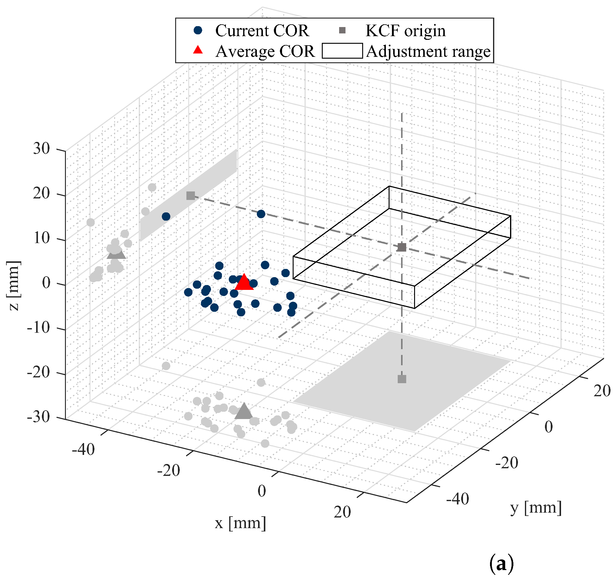
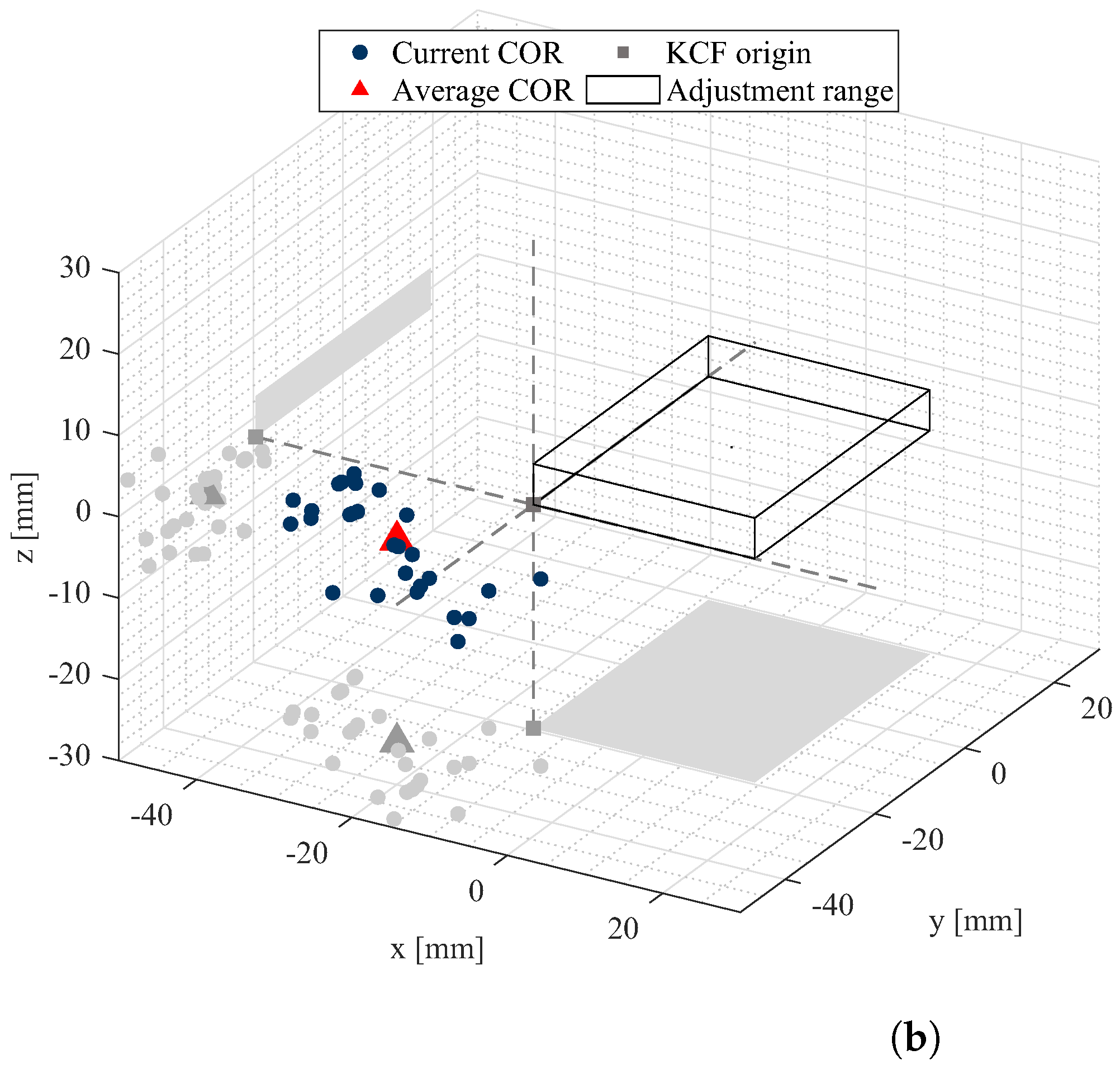
This can be illustrated by looking at an exemplary measurement (Figure 8). The existing adjustment range of the exoskeleton mechanics is shown as a rectangular space with the KCF origin in the center during the first trial (Figure 8a). Following the movement pattern, the current COR of the shoulder joint was determined for small angular segments (points of the scatter diagram), and an average rotation point (red triangle) was calculated. In both trials (Figure 8a,b), the calculated average COR remained in nearly the same position, with a deviation of . The results of the second trial also show that the adjustments made improved the alignment of the exoskeleton to the participant, emphasizing the potential of the method to support a more accurate adaptation to individual anthropometry. However, it stayed outside the system’s kinematic structure’s adjustable range, indicating that the design limitations prevented proper alignment, even when the maximum settings were applied in the second trial.
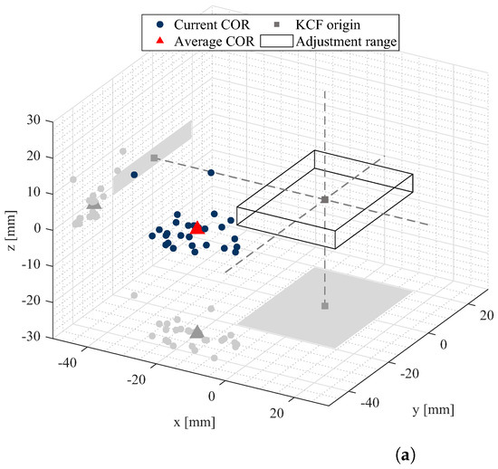
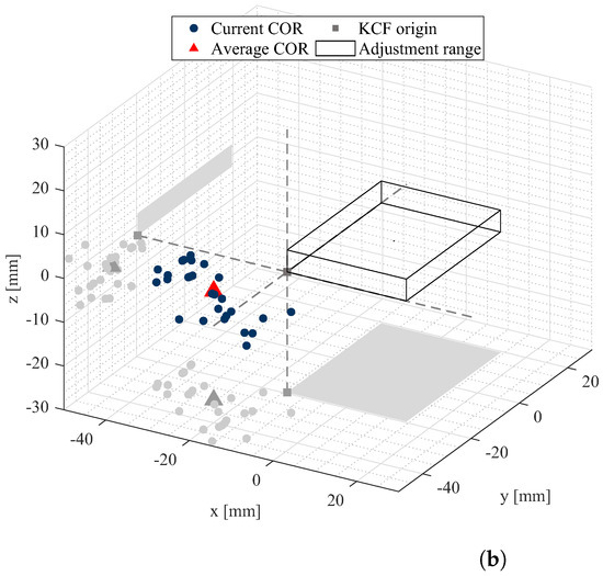
Figure 8.
Comparison of the first and second trials of a participant with a deviation of between the calculated average CORs. (a) First trial: centered setting of the mechanical structure. (b) Second trial: adjusted setting of the mechanical structure.
7. Conclusions and Outlook
This paper presents a method to measure the spatial displacement induced by axis misalignment and to derive adjustment instructions for enhancing the anthropometric fit of an exoskeleton. Validation with both 2D and 3D mock-ups, as well as a preliminary study using the shoulder exoskeleton “Lucy”, demonstrated the feasibility of the approach under controlled conditions. While these results are promising, the present study represents an initial step that primarily focused on static spatial misalignment and has not yet incorporated detailed dynamic analyses or soft tissue influences.
Future work will concentrate on several key areas. An expanded investigation of the kinematic adaptation space and incorporated dynamic analysis are needed to capture the exoskeleton’s performance during real-world activities. Building on these findings, an increasing number and diversity of participants will provide a more robust foundation for the statistical analysis needed to address the variability in anthropometry. Also, improvements in the hardware design, particularly further reducing the clearance and refining sensor accuracy, will enhance the overall system precision. Moreover, refining the exoskeleton’s shoulder kinematics by incorporating internal and external rotations will further enhance the anthropometric alignment, extend the supported range of motion, and potentially increase the user comfort.
Building on these modifications, the method could enable the spatial position of the joint to be recorded during the activities. This information can then be used to analyze whether forward-looking adjustments to anthropometry are necessary for specific tasks, especially for mobile joints, such as the shoulder. These adjustments could become relevant if, during the activity, the joint ends up in a different position than it was in the user’s initial posture.
The method presented here provides an initial approach to assisted anthropometric adaptation using the exoskeleton. At the same time, the approach provides the basis for further investigations into the interaction between humans and exoskeletons, enabling additional steps toward optimally anthropometrically adapted exoskeletons.
Author Contributions
Conceptualization, O.O., S.E. and N.K.; methodology, O.O., S.E. and N.K.; software, O.O., S.E. and N.K.; validation, O.O., S.E. and N.K.; formal analysis, O.O., S.E. and N.K.; investigation, O.O., S.E. and N.K.; resources, R.W.; data curation, O.O. and N.K.; writing—original draft preparation, O.O. and S.E.; writing—review and editing, O.O., S.E. and R.W.; visualization, O.O., S.E. and N.K.; supervision, R.W. All authors read and agreed to the published version of this manuscript.
Funding
The publication of this article has proportionally been funded by the Publication Fund of the University of Innsbruck.
Data Availability Statement
Dataset available on request from the authors.
Conflicts of Interest
The authors declare no conflicts of interest.
Nomenclature
| ROM | Range of motion |
| DOF | Degree of freedom |
| COR | Center of rotation |
| KCF | Exoskeleton’s kinematic coordinate frame |
| r | Distance between the center of rotation M and the contact point P |
| M | Center of rotation of the human joint |
| Spatial misalignment between the axes of the exoskeleton and the human joint | |
| Relative distance to the current interface location | |
| Initial length, i.e., distance to the initial position of the interface | |
| Compensated relative axial displacement | |
| Angle of rotation to the contact point | |
| Relative angular deviation between the human and the interface during the rotation | |
| Additional angle of rotation to the contact point in 3D | |
| Measured contact point between the exoskeleton and the human | |
| Cartesian coordinates of the center of rotation M (KCF) | |
| Cartesian coordinates of the measured contact point (KCF) | |
| DOF A | Exoskeleton’s translational degree of freedom for measuring and compensating for the offset |
| DOF I | Exoskeleton’s transverse axis of rotation, angle quantified by |
| DOF | Exoskeleton’s longitudinal axis of rotation, angle quantified by |
References
- Casla, P.; Larreina, J.; Fletcher, S.; Johnson, T.; Parigot, L.; Otero, M.; Adlon, T.; Riegauf, A.; Marguglio, A.; Kaasinen, E.; et al. Human-Centered Factories from Theory to Industrial Practice. Lessons Learned and Recommendations; humAn CEntred Factories (ACE): Brussels, Belgium, 2019. [Google Scholar]
- Mark, B.G.; Rauch, E.; Matt, D.T. Worker assistance systems in manufacturing: A review of the state of the art and future directions. J. Manuf. Syst. 2021, 59, 228–250. [Google Scholar] [CrossRef]
- de Looze, M.P.; Bosch, T.; Krause, F.; Stadler, K.S.; O’Sullivan, L.W. Exoskeletons for industrial application and their potential effects on physical work load. Ergonomics 2016, 59, 671–681. [Google Scholar] [CrossRef] [PubMed]
- Pech, M.; Vrchota, J. The Product Customization Process in Relation to Industry 4.0 and Digitalization. Processes 2022, 10, 539. [Google Scholar] [CrossRef]
- Eurofound; Wilczynska, A.; Cabrita, J.; Parent-Thirion, A.; Biletta, I.; Vargas, O.; Wilkens, M.; Vermeylen, G. 6th European Working Conditions Survey—2017 Update; Publications Office: Luxembourg, 2017. [Google Scholar] [CrossRef]
- Ralfs, L.; Hoffmann, N.; Weidner, R. Method and Test Course for the Evaluation of Industrial Exoskeletons. Appl. Sci. 2021, 11, 9614. [Google Scholar] [CrossRef]
- European Agency for Safety and Health at Work; IKEI; Panteia; Kok, J.d.; Vroonhof, P.; Snijders, J.; Roullis, G.; Clarke, M.; Peereboom, K.; Dorst, P.v.; et al. Work-Related Musculoskeletal Disorders—Prevalence, Costs and Demographics in the EU; Publications Office: Luxembourg, 2019. [Google Scholar] [CrossRef]
- de La Tejera, J.A.; Bustamante-Bello, R.; Ramirez-Mendoza, R.A.; Izquierdo-Reyes, J. Systematic Review of Exoskeletons towards a General Categorization Model Proposal. Appl. Sci. 2021, 11, 76. [Google Scholar] [CrossRef]
- Mark, B.G.; Rauch, E.; Matt, D.T. Systematic selection methodology for worker assistance systems in manufacturing. Comput. Ind. Eng. 2022, 166, 107982. [Google Scholar] [CrossRef]
- Maurice, P.; Camernik, J.; Gorjan, D.; Schirrmeister, B.; Bornmann, J.; Tagliapietra, L.; Latella, C.; Pucci, D.; Fritzsche, L.; Ivaldi, S.; et al. Objective and Subjective Effects of a Passive Exoskeleton on Overhead Work. IEEE Trans. Neural Syst. Rehabil. Eng. A Publ. IEEE Eng. Med. Biol. Soc. 2020, 28, 152–164. [Google Scholar] [CrossRef]
- Schmalz, T.; Schändlinger, J.; Schuler, M.; Bornmann, J.; Schirrmeister, B.; Kannenberg, A.; Ernst, M. Biomechanical and Metabolic Effectiveness of an Industrial Exoskeleton for Overhead Work. Int. J. Environ. Res. Public Health 2019, 16, 4792. [Google Scholar] [CrossRef]
- Liang, J.; Zhang, Q.; Liu, Y.; Wang, T.; Wan, G. A review of the design of load-carrying exoskeletons. Sci. China. Technol. Sci. 2022, 65, 2051–2067. [Google Scholar] [CrossRef]
- Ott, O.; Ralfs, L.; Weidner, R. Framework for qualifying exoskeletons as adaptive support technology. Front. Robot. AI 2022, 9, 951382. [Google Scholar] [CrossRef]
- Näf, M.B.; Junius, K.; Rossini, M.; Rodriguez-Guerrero, C.; Vanderborght, B.; Lefeber, D. Misalignment Compensation for Full Human-Exoskeleton Kinematic Compatibility: State of the Art and Evaluation. Appl. Mech. Rev. 2018, 70, 050802. [Google Scholar] [CrossRef]
- Xiloyannis, M.; Alicea, R.; Georgarakis, A.M.; Haufe, F.L.; Wolf, P.; Masia, L.; Riener, R. Soft Robotic Suits: State of the Art, Core Technologies, and Open Challenges. IEEE Trans. Robot. 2022, 38, 1343–1362. [Google Scholar] [CrossRef]
- Goršič, M.; Song, Y.; Dai, B.; Novak, V.D. Short-term effects of the Auxivo LiftSuit during lifting and static leaning. Appl. Ergon. 2022, 102, 103765. [Google Scholar] [CrossRef]
- Lindemann, U.; Krespach, J.; Daub, U.; Schneider, M.; Sczuka, K.S.; Klenk, J. Effect of a Passive Exosuit on Sit-to-Stand Performance in Geriatric Patients Measured by Body-Worn Sensors-A Pilot Study. Sensors 2023, 23, 1032. [Google Scholar] [CrossRef]
- Lei, T.; Seo, J.; Liang, K.; Xu, J.; Li, H.; Zhou, Y.; Khan, M.; Heung, K.H. Lightweight Active Soft Back Exosuit for Construction Workers in Lifting Tasks. J. Constr. Eng. Manag. 2024, 150, 04024073. [Google Scholar] [CrossRef]
- Bajpai, A.; Carrasquillo, C.; Carlson, J.; Park, J.; Iyengar, D.; Herrin, K.; Young, A.J.; Mazumdar, A. Design and Validation of a Versatile High Torque Quasidirect Drive Hip Exoskeleton. IEEE/ASME Trans. Mechatron. 2024, 29, 789–797. [Google Scholar] [CrossRef]
- Park, D.; Toxiri, S.; Chini, G.; Di Natali, C.; Caldwell, D.G.; Ortiz, J. Shoulder-sideWINDER (Shoulder-side Wearable INDustrial Ergonomic Robot): Design and Evaluation of Shoulder Wearable Robot With Mechanisms to Compensate for Joint Misalignment. IEEE Trans. Robot. 2022, 38, 1460–1471. [Google Scholar] [CrossRef]
- Weidner, R.; Karafillidis, A. Distinguishing Support Technologies. A General Scheme and Its Application to Exoskeletons. In Developing Support Technologies. Biosystems & Biorobotics; Karafillidis, A., Weidner, R., Eds.; Springer International Publishing: Cham, Switzerland, 2018; Volume 23, pp. 85–100. [Google Scholar] [CrossRef]
- Auxivo, A.G. CarrySuit—The Upper Body Exoskeleton. 2024. Available online: https://www.auxivo.com/carrysuit (accessed on 18 December 2024).
- SuitX. IX SHOULDER AIR Exoskeleton. 2024. Available online: https://www.suitx.com/de/produkte/ix-shoulder-air-exoskelett (accessed on 18 December 2024).
- Lockheed Martin. Let the FORTIS® Tool Arm Give You a Hand. 2017. Available online: https://news.lockheedmartin.com/2017-04-20-Let-the-FORTIS-R-Tool-Arm-Give-You-a-Hand (accessed on 18 December 2024).
- SuitX. IX BACK Exoskeleton. 2024. Available online: https://www.suitx.com/de/produkte/ix-back-exoskelett (accessed on 18 December 2024).
- Levitate Technologies. Airframe Exoskeleton. 2024. Available online: https://www.levitatetech.com/airframe/ (accessed on 18 December 2024).
- Comau. Wearable Robotics—MATE XT Exoskeleton. 2024. Available online: https://www.comau.com/en/our-offer/products-and-solutions/wearable-robotics-exoskeletons/wearable-robotics-mate-xt-exoskeleton/ (accessed on 18 December 2024).
- Yoon, J.; Kim, S.; Moon, J.; Kim, J.; Lee, G. Minimizing Misalignment and Frame Protrusion of Shoulder Exoskeleton via Optimization for Reducing Interaction Force and Minimizing Volume. Machines 2022, 10, 1223. [Google Scholar] [CrossRef]
- Pons, J.L. Wearable Robots: Biomechatronic Exoskeletons; John Wiley & Sons: Hoboken, NJ, USA, 2008. [Google Scholar]
- Schiele, A.; van der Helm, F.C.T. Kinematic design to improve ergonomics in human machine interaction. IEEE Trans. Neural Syst. Rehabil. Eng. A Publ. IEEE Eng. Med. Biol. Soc. 2006, 14, 456–469. [Google Scholar] [CrossRef]
- Zanotto, D.; Akiyama, Y.; Stegall, P.; Agrawal, S.K. Knee Joint Misalignment in Exoskeletons for the Lower Extremities: Effects on User’s Gait. IEEE Trans. Robot. 2015, 31, 978–987. [Google Scholar] [CrossRef]
- Kim, T.; Jeong, M.; Kong, K. Bioinspired Knee Joint of a Lower-Limb Exoskeleton for Misalignment Reduction. IEEE/ASME Trans. Mechatron. 2022, 27, 1223–1232. [Google Scholar] [CrossRef]
- Orsted, H.L.; Ohura, T.; Harding, K. International review. Pressure ulcer prevention: Pressure, shear, friction and microclimate in context. A consensus document. Wounds Int. 2010, 26, 1. [Google Scholar]
- Mallat, R.; Khalil, M.; Venture, G.; Bonnet, V.; Mohammed, S. Human-Exoskeleton Joint Misalignment: A Systematic Review. In Proceedings of the 2019 Fifth International Conference on Advances in Biomedical Engineering (ICABME), Tripoli, Lebanon, 17–19 October 2019; pp. 1–4. [Google Scholar] [CrossRef]
- Doorenbosch, C.A.; Mourits, A.J.; Veeger, D.H.; Harlaar, J.; van der Helm, F.C. Determination of functional rotation axes during elevation of the shoulder complex. J. Orthop. Sport. Phys. Ther. 2001, 31, 133–137. [Google Scholar] [CrossRef] [PubMed]
- Veeger, H.E. The position of the rotation center of the glenohumeral joint. J. Biomech. 2000, 33, 1711–1715. [Google Scholar] [CrossRef]
- Schorsch, J.F.; Keemink, A.Q.L.; Stienen, A.H.A.; van der Helm, F.C.T.; Abbink, D.A. A novel self-aligning mechanism to decouple force and torques for a planar exoskeleton joint. Mech. Sci. 2014, 5, 29–35. [Google Scholar] [CrossRef]
- Stienen, A.; Hekman, E.; van der Helm, F.; van der Kooij, H. Self-Aligning Exoskeleton Axes Through Decoupling of Joint Rotations and Translations. IEEE Trans. Robot. 2009, 25, 628–633. [Google Scholar] [CrossRef]
- Van der Helm, F.C.T. A standardized protocol for motions recordings of the shoulder. In First Conference of the International Shoulder Group; Veeger, H.E.J., Van der Helm, F.C.T., Rozing, P.M., Eds.; Shaker Publishing: Maastricht, The Netherlands, 1997; pp. 1–7. [Google Scholar]
- Clark, R.; Dickinson, T.; Loaiza, J.; Geiger, D.W.; Charles, S.K. Tracking Joint Angles During Whole-Arm Movements Using Electromagnetic Sensors. J. Biomech. Eng. 2020, 142, 074502. [Google Scholar] [CrossRef]
- El-Gohary, M.; McNames, J. Shoulder and elbow joint angle tracking with inertial sensors. IEEE Trans. Bio-Med Eng. 2012, 59, 2635–2641. [Google Scholar] [CrossRef]
- Illyés, A.; Kiss, R.M. Shoulder joint kinematics during elevation measured by ultrasound-based measuring system. J. Electromyogr. Kinesiol. Off. J. Int. Soc. Electrophysiol. Kinesiol. 2007, 17, 355–364. [Google Scholar] [CrossRef]
- Otten, B.M.; Weidner, R.; Argubi-Wollesen, A. Evaluation of a Novel Active Exoskeleton for Tasks at or Above Head Level. IEEE Robot. Autom. Lett. 2018, 3, 2408–2415. [Google Scholar] [CrossRef]
- Chernov, N. Circle Fit (Pratt Method). MATLAB Central File Exchange. 2024. Available online: https://www.mathworks.com/matlabcentral/fileexchange/22643-circle-fit-pratt-method (accessed on 20 March 2024).
- Della Croce, U.; Leardini, A.; Chiari, L.; Cappozzo, A. Human movement analysis using stereophotogrammetry: Part 4: Assessment of anatomical landmark misplacement and its effects on joint kinematics. Gait Posture 2005, 21, 226–237. [Google Scholar] [CrossRef]
Disclaimer/Publisher’s Note: The statements, opinions and data contained in all publications are solely those of the individual author(s) and contributor(s) and not of MDPI and/or the editor(s). MDPI and/or the editor(s) disclaim responsibility for any injury to people or property resulting from any ideas, methods, instructions or products referred to in the content. |
© 2025 by the authors. Licensee MDPI, Basel, Switzerland. This article is an open access article distributed under the terms and conditions of the Creative Commons Attribution (CC BY) license (https://creativecommons.org/licenses/by/4.0/).

