Abstract
During the maintenance of railway fasteners, there are issues with the current nut disassembly and assembly operation, including low efficiency, heavy reliance on manual labor, and high physical strain. A mechanical device has been designed to move along the railway track while identifying and locating the center of the nut to perform disassembly and assembly operations. First, based on the nut disassembly and assembly process and the operating environment, the structure of the equipment was designed. This machine can simultaneously disassemble and assemble all the nuts on a single rail tie and accommodate position errors and deviations of spiral spikes. Secondly, to verify the structural reliability of the designed machine, a static simulation analysis was conducted on the key load-bearing structures under extreme operating conditions. Based on the simulation results, a lightweight design was applied to the machine’s carrier platform. The performance of the nut assembly and disassembly mechanism was optimized based on the Kriging model and the Non-dominated Sorting Genetic Algorithm (NSGA-II). The optimized machine reduced its mass by 21.7% and increased its strength by more than 30%. A transient analysis was also conducted on the optimized machine structure, further validating its strength. Finally, based on the design and optimization results, a physical prototype of the nut disassembly machine was constructed and tested. The results show that the device can efficiently perform nut disassembly and assembly tasks on the railway track. Both the mechanical structure’s reliability and functionality meet the design objectives and requirements, demonstrating significant application value for promoting the intelligent maintenance of railways.
1. Introduction
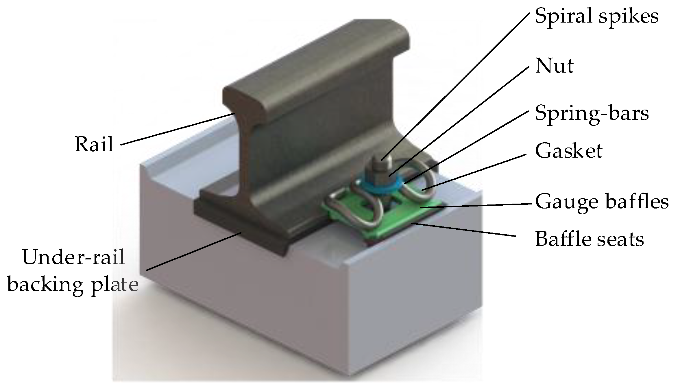
The railway fastener system is a key component connecting the rail to the underlying structure. Its main functions include transferring the dynamic loads from the train, restricting the longitudinal and lateral displacement of the rail, preventing track overturning, and maintaining the required insulation and elasticity of the track, ensuring the safe operation of the railway [1,2]. Threads connect the nut and spiral spike to compress the spring clip and apply sufficient fastening pressure to the rail [3]. The fastener system is exposed to outdoor environments for extended periods and subjected to complex and variable loads. Over time, issues such as spring clip loosening, spiral spike bending, or breakage can occur [4,5]. These problems significantly reduce the adequate fastening pressure exerted on the rail, thereby decreasing the safety and reliability of railway operations [6]. Therefore, regular maintenance of the fastener system has become essential to ensure smooth and safe railway operation and prevent track accidents [7]. The Type II elastic clip system is shown in Figure 1.
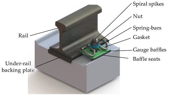
Figure 1.
Schematic diagram of the construction of elastic bar type II fasteners.
The nut disassembly and assembly operation involves tightening and loosening nuts. The traditional method typically relies on workers using internal combustion and hexagonal wrenches for disassembly and assembly. This approach highly depends on the operator’s experience, resulting in low efficiency, increased need for torque checks, and a waste of valuable “window working time” [8,9,10]. Since railways are primarily laid in outdoor environments with harsh working conditions, manual nut disassembly and assembly are labor-intensive and incur high labor costs, further limiting the efficiency and quality of maintenance work [11,12]. To achieve the goal of “machines replacing human labor”, mechanized equipment is used for the automated disassembly and assembly of nuts. The developed machinery must be capable of accommodating the positional errors and misalignments of the spiral spikes during the installation and use of the nuts [13].
Additionally, to prevent track tilting and overturning during nut disassembly and assembly, the machine should be able to simultaneously disassemble and assemble nuts on both sides of a single rail [14]. Cheng Xianji and Liu Chuan, among others, designed a nut disassembly and oiling device and a mechanized fastener removal device, both of which improved the efficiency of nut disassembly and assembly. However, the former still requires manual assistance and has not achieved full automation. At the same time, the latter addresses some fundamental issues in the nut disassembly process but still has limitations in dealing with the randomness and misalignment of spiral spike positions. Moreover, the device is currently in the conceptual phase and has not been widely implemented [15,16].
In optimization design, multi-objective optimization selects the optimal solution from all feasible solutions to a problem based on specific criteria. In multi-objective optimization problems with conflicting objectives, there is no single optimal solution; instead, a set of non-dominated solutions exists for decision-makers to choose from [17]. Chao Liu [18] used a combined method of Response Surface Methodology (RSM) and the Non-dominated Sorting Genetic Algorithm (NSGA-II) to optimize the groove structure parameters of a torque sensor, aiming to reduce the impact of bending moments on the sensor’s performance. The effectiveness of this multi-objective optimization method was verified by comparing the sensitivity curves of the sensor before and after optimization. Hao Li [19] explored the impact of rotor blade structure on the performance of a vertical mill and proposed a structural optimization design method for the classifier based on the Kriging surrogate model, which was optimized and validated on the Insight platform. This method effectively improves rotor torque and airflow speed between rotor blades. Liu Gaozhao [20] took an 80 MN forging hydraulic press as the research object and used Response Surface Methodology based on static stress cloud maps to optimize dimensions that significantly impact the robotic arm, reducing material waste and production costs. The structure is subjected to alternating loads during operation, and fatigue failure is the primary cause of structural failure. Standard stress-reducing methods include selecting high-strength materials, surface treatments, and optimizing part dimensions and shapes [21]. Estimating the fatigue life of the designed machine structure is significant for preventing fatigue fractures and guiding mechanical structures’ design, manufacturing, maintenance, and management.
Based on the technical challenges in the nut disassembly and assembly operation and considering the working conditions and fastener specifications, a high-torque nut disassembly machine was designed to accommodate the position errors and misalignments of spiral spikes. During the design process, finite element analysis (FEA) of the key structures of the nut disassembly machine was conducted using ANSYS 2018 software. Static analysis results helped identify potential structural redundancies and weak points in the design, guiding the optimization direction. The machine was subjected to a lightweight design approach, and the strength and lifespan of the device were enhanced using the optimization method that combined the Kriging surrogate model and NSGA-II algorithm. Furthermore, the machine’s performance was tested to evaluate its efficiency and reliability. The designed nut disassembly machine significantly improves the efficiency and quality of nut disassembly, reduces workers’ physical labor, and substantially contributes to the automation and intelligentization of railway fastener maintenance. It offers a solid foundation for enhancing the safety and reliability of railway operations.
In this article, we propose a specialized machine for dismantling and assembling rail fastening nuts in China, replacing the current manual method. The contributions and conclusions of this research are summarized as follows:
- The nut assembly and disassembly machine designed in this article can simultaneously handle all the nuts on a single sleeper on a straight track. It can adapt, to some extent, to the positional errors and misalignments of the spiral spikes;
- A lightweight design of the transport platform was implemented through static mechanical analysis of the designed machine structure to improve the overall quality and durability in disassembly operations. Based on the impact of the design parameters of the nut assembly and disassembly structure on its performance, an optimization method using a Kriging surrogate model and the NSGA-II algorithm was adopted to enhance the strength and lifespan of the equipment;
- In order to validate the designed machine, it was tested on the tracks of the Xi’an Locomotive Depot. The tests measured the success rate of the machine during the sleeve and nut-fitting process. Its operational efficiency was compared with the current dual-head internal combustion engine disassembly wrench, demonstrating the machine’s reliability and efficiency.
2. Structural Design and Analysis of the Nut Disassembly Machine
2.1. Process and Environmental Analysis
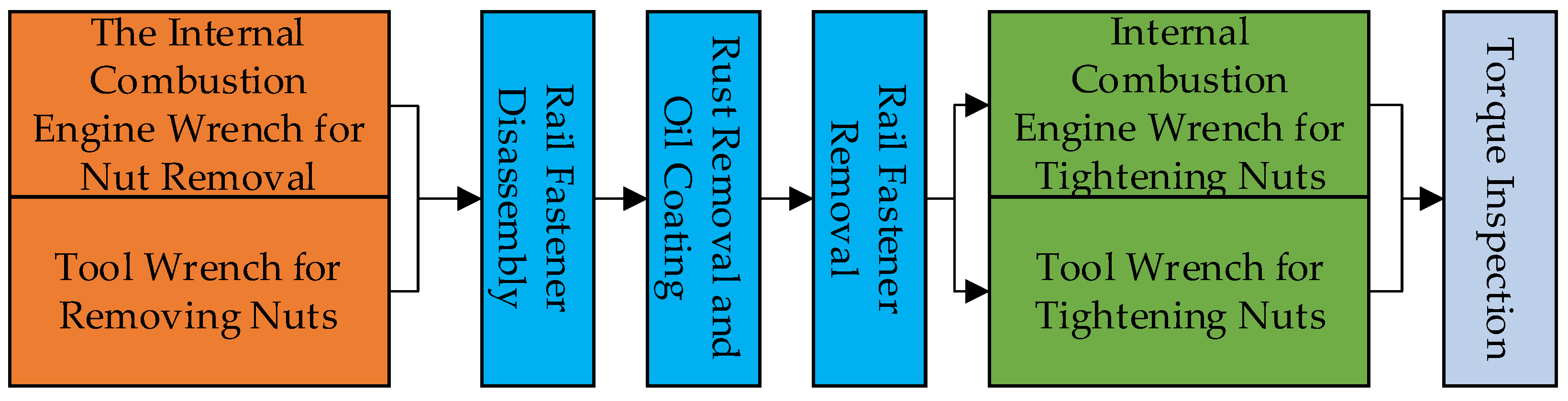
The maintenance process of railway fasteners is shown in Figure 2. An analysis of the railway fastening maintenance process shows that the entire workflow relies on collaborative efforts from multiple workers. During this process, tightening and loosening the nuts are the most labor-intensive. Workers use gasoline engine wrenches to disassemble and assemble the nuts, positioning them based on visual alignment and pressing the socket to complete the nut disassembly. Workers can only use a hex wrench to loosen high-torque nuts when dealing with them. After tightening the nuts, random torque checks are required, which increases the time needed for the entire maintenance process. In order to improve the maintenance efficiency of fasteners and nuts and reduce labor costs and labor intensity, it is necessary to use industrial machines to replace manual labor in the nut disassembly and assembly steps.
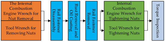
Figure 2.
Maintenance process of railway fasteners.
According to the “TBT 3065-2020 Spring Clip Type II Fastening Specification”, the standard track gauge for railways in China is 1435 mm, with a rail width of 70 mm. The rail nuts are installed symmetrically on the inner and outer sides of the track, with a center-to-center distance of 214 mm. Spiral spikes are embedded in concrete railroad ties, exposing a bolt length of approximately 80 mm. The spacing between adjacent railroad ties is typically 500–700 mm, and the tightening torque is 120–140 N·m. During the manual installation of the spiral spikes and railroad ties, specific positional errors can occur, leading to an actual rail center distance equal to the sum of the standard track gauge, the rail width, and the adjusted track gauge.
Under the variable loads during train operation, the spiral spikes deform and become misaligned, causing changes in the angle between the spiral spike and the railroad tie, increasing the torque required to loosen the nut. Moreover, during the long-term use of the fastening system, the spiral spikes and nuts, exposed to the open environment for extended periods, undergo varying degrees of rusting, further affecting the nut loosening torque. This effect is complex and difficult to quantify precisely through calculations. According to field survey data, the torque required to loosen the fastening nuts ranges from 240 to 350 N·m.
2.2. Overall Structural Design
The nut disassembly machine should be capable of continuing operations in complex outdoor environments, even when positional errors and spiral spike misalignments occur. At the same time, while ensuring the equipment’s operational safety and functional feasibility, the overall structure should be optimized as much as possible to reduce the size and weight of the device. Reducing the economic cost and labor intensity of the equipment in the process of use and transportation also has a positive impact on improving the battery life of the whole machine. Figure 3 is a schematic diagram of the designed nut disassembly machine.
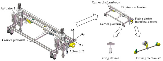
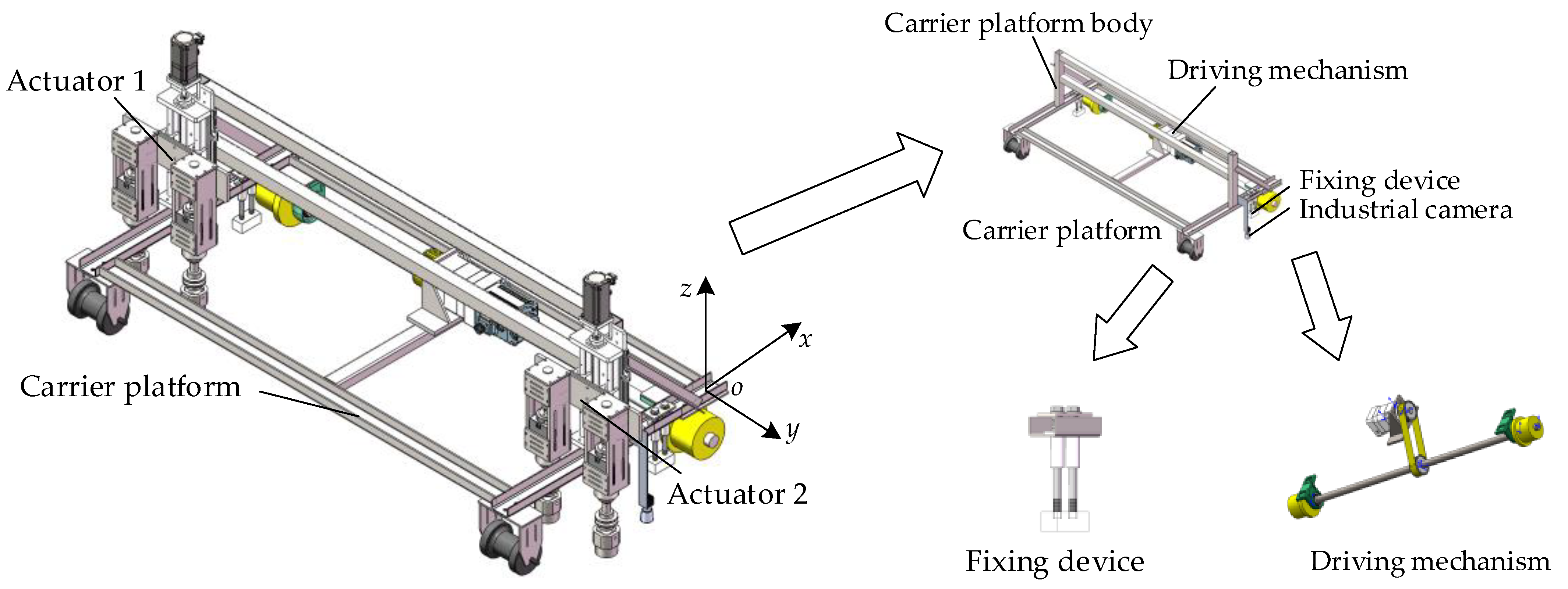
Figure 3.
Schematic diagram of the structure of the nut disassembly machine.
According to the railway fastener nuts’ current disassembly and assembly process, a modular design approach is used to layer the machine’s functions. A nut disassembly robot was designed, as shown in the Figure 3. The machine mainly consists of a carrier platform, a vision detection system, and an actuator. The carrier platform enables movement along the x-axis and functions to fix and bear loads. Considering the coordinated relationship between the actuator’s feeding motion and disassembly function, the Z-axis feeding motion is integrated into the actuator. The carrier platform is equipped with four actuators, allowing for the disassembly and assembly of four nuts on a single railroad tie. The robot is powered by a lithium battery (48 V/60 A·h) and has an endurance time of over 6 h. The key parameters of the machine are listed in Table 1:

Table 1.
Key parameters of the machine.
2.2.1. Carrier Platform
The carrier platform mainly comprises the carrier platform body, the driving device, and the fixing device, and its structural schematic diagram is shown in Figure 3. The platform body uses Q355B carbon steel in a portal frame structure. The drive mechanism uses a synchronous belt drive positioned at the center of the front drive wheel, enabling machine point-to-point movement along the track. The drive wheel is a track wheel, which helps restrict the machine’s offset and ensures it moves along the direction of the track. A fixing device is introduced on both sides of the carrier platform body to ensure positioning accuracy. During the machine’s disassembly and assembly operations, the fixing device adsorbs to the rail, preventing the machine from sliding laterally or longitudinally under heavy loads.
2.2.2. Actuator
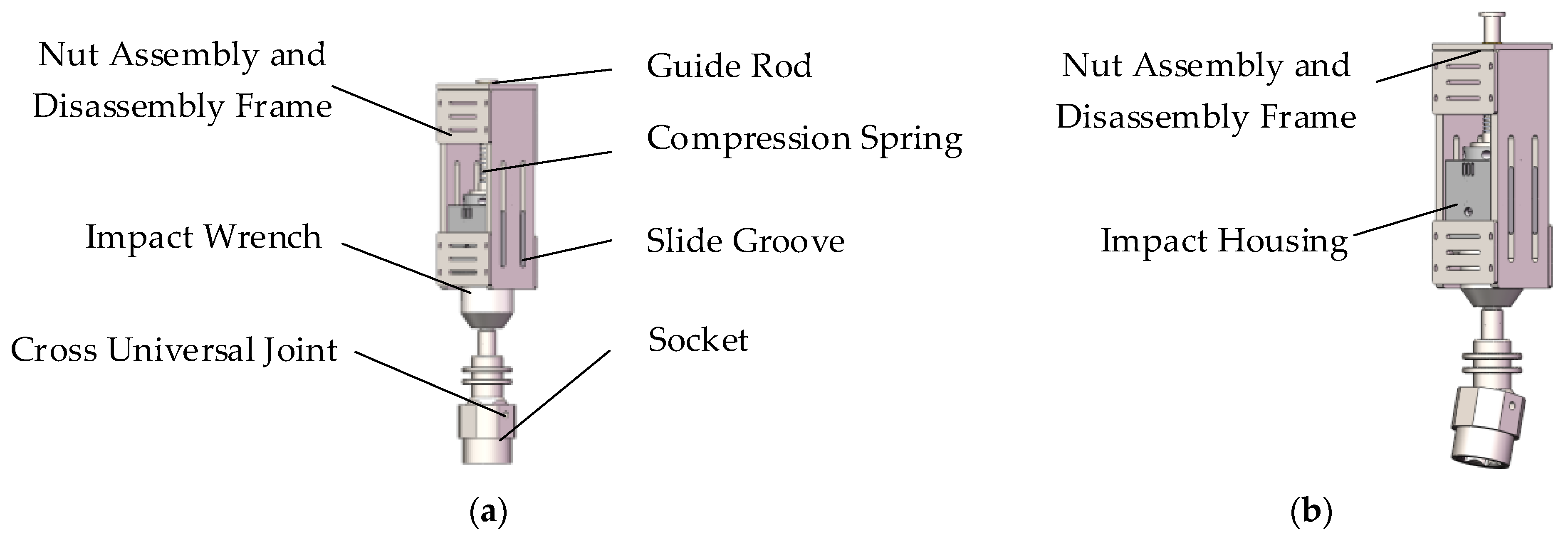
This mainly includes the feeding and nut disassembly and assembly mechanisms. The ball screw assembly is used as the feeding mechanism due to its high positioning accuracy and reliability [22]. It is driven by a Z-axis motor to achieve feeding motion along the Z-axis. Figure 4 is a schematic representation of the operator’s results.
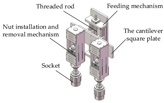
Figure 4.
Structure of the actuator.
The nut disassembly and assembly mechanism consists of the disassembly frame, impact wrench, universal cross joint, and socket. A brushless DC motor powers the impact wrench, and through a gearbox and impact structure, it amplifies the torque. The output shaft of the impact wrench is directly connected to the universal joint, driving the socket to disassemble and assemble the nut. The impact wrench is mounted in the disassembly frame through an impact casing. During the installation and use of the spiral spike, positional errors and misalignments can occur, leading to a situation where the nut’s central axis does not align with the socket’s central axis. The universal cross joint [23] transmits the torque. It improves the machine’s adaptability, ensuring that the socket can still engage with the nut even when the spike is misaligned or there is a positional error.
In machine operation, the machine is damaged to avoid the rigid extrusion caused by the sleeve and the nut when it is not successfully matched. The chute and guide rod are designed in the frame of the disassembly and assembly mechanism. The disassembly frame is designed with a sliding groove and guide rods to restrict and guide the impact wrench’s axial movement in the vertical direction. The guide rods are connected to the top of the impact casing via flanges. The keys on both sides of the impact casing, along with the sliding groove on the disassembly frame, form a movable pair, allowing the impact wrench to move up and down for adjustment when the nut’s central axis does not align with the socket’s central axis [24]. Additionally, to further enhance the recovery ability of the disassembly mechanism, a preloaded spring is designed on the outer side of the guide rods. This design not only ensures that the actuator quickly returns to its initial position after completing the operation but also ensures that the socket consistently applies downward preload to the nut during the operation, thereby improving the reliability of the process. Figure 5 represents the two states when the nut disassembly and assembly mechanism operates; a feature is that the center line of the sleeve coincides with the center axis of the nut, and B is the center line of the sleeve, which does not coincides with the center axis of the nut.

Figure 5.
The nut disassembly mechanism has different working conditions. (a) Initial state; (b) compressed state.
2.2.3. Socket Design
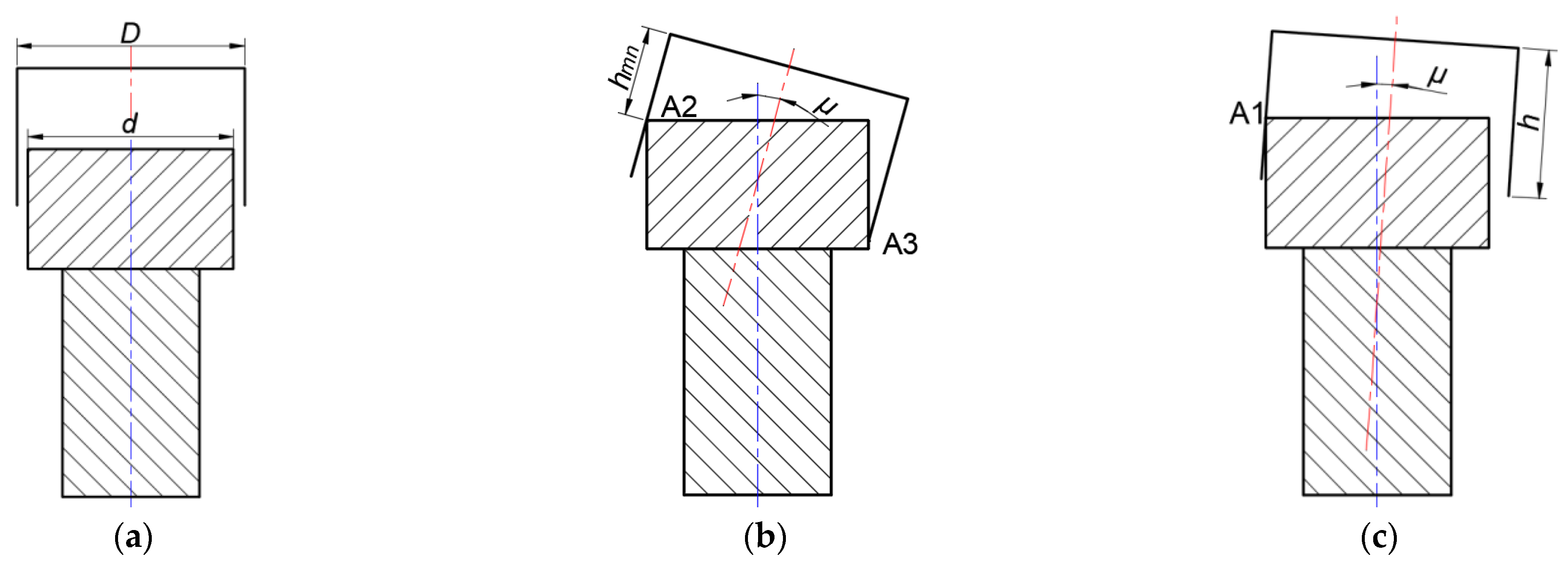
As the socket descends, the greater is the angle between its central axis and the nut’s central axis [25] and the worse is the guiding performance of the socket on the nut, which may even lead to jamming, thus affecting the efficiency of the disassembly and assembly process. The socket and nut engagement issue can be regarded as a typical shaft-hole fit problem. An appropriate socket size can be selected to reduce the risk of jamming during the nut disassembly and assembly process by analyzing the maximum allowable angular deviation between the shaft and hole assembly. The various shaft-hole fit conditions are shown in Figure 6:
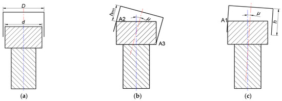
Figure 6.
Shaft hole fit model. (a) Axis coincidence; (b) single-point contact; (c) two-point contact.
Δx is the axial clearance; according to the geometric relationship of shaft-hole fits from reference [26], the relationship between different sleeve diameters and Δx are listed in Table 2:
Table 2.
The relationship between different socket diameters and axial clearance.
The successful fit between the nut and the sleeve must also consider whether it satisfies the friction conditions. According to the friction self-locking theory from reference [27],
where f is the coefficient of friction between the sleeve and the nut (with a value of 0.2) and the sleeve’s depth is 30 mm; the maximum value of Δx without friction self-locking is 5.88 mm.
The operational error of the nut disassembly machine originates from the position error of the spiral spike and the system error of the machine [28]. The designed nut disassembly machine operates on a straight track, with a system error within 2 mm. The installation error of the spiral spike is ±2 mm, and the maximum deviation error is ±2.84 mm. Therefore, a sleeve with a maximum inscribed circle diameter of 38 mm was selected as the machine’s end effector, which can effectively increase the sleeve’s insertion rate, thereby improving the success rate of the disassembly and assembly operation.
2.3. Finite Element Analysis of Key Structures
2.3.1. Static Analysis of the Carrier Platform
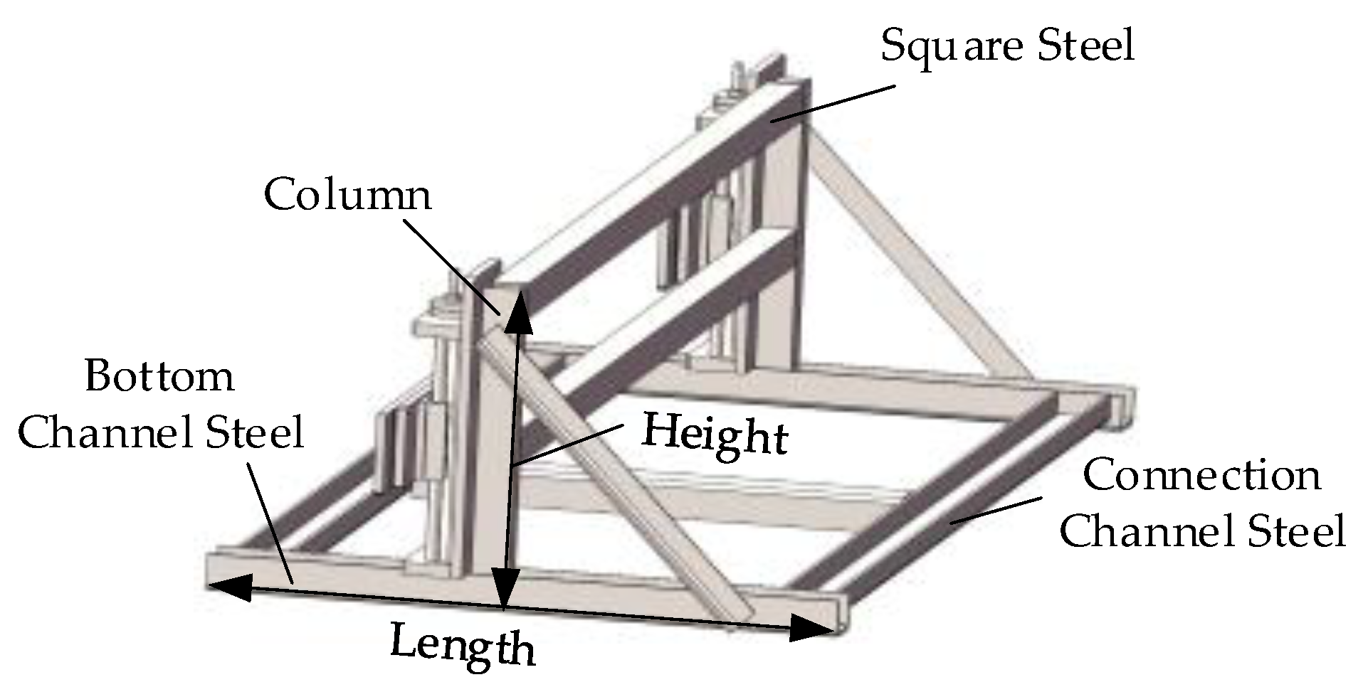
During the nut disassembly process, the carrier platform is subjected to the most remarkable reaction force from the gravity of the actuator and the reaction force during the disassembly of high-torque nuts. The material used for the platform is Q355 steel. When modeling the carrier platform, the structure is connected using welded stiffeners, and the gaps between the main platform components are modeled either through weld seam modeling or by stretching and merging welded parts to ensure calculation accuracy [29]. The simplified model of the carrier platform is shown in Figure 7.
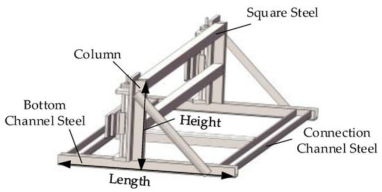
Figure 7.
Simplified model of the carrier platform.
The model was imported into Workbench, and the structural material was defined. In order to improve the accuracy of the calculations in the simulation analysis process, adjustments can be made to the mesh division method and mesh size [30]. The mesh generation results are as follows: the minimum element mass was 0.002, the maximum mass was 0.999, and the average mass was 0.836, which met simulation requirements. A total of 371,845 elements and 1,026,849 nodes were generated. Loads and constraints were applied to the carrier platform structure according to the extreme working conditions, with a torque of 350 N·m applied. Figure 8 shows the static simulation results of the carrier platform during the disassembly of high-torque nuts.
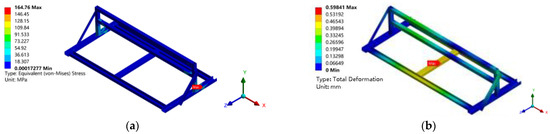
Figure 8.
Static simulation of the carrier platform. (a) Equivalent stress contour map; (b) total deformation contour map.
The figure shows that the maximum equivalent stress of the carrier platform is 164.76 MPa, and the total deformation is 0.59 mm. The maximum stress occurs near the connection between the column and the bottom channel steel and is much smaller than the yield strength of Q355 steel (355 Mpa), and the other structures of the carrier platform experience relatively small maximum equivalent stresses. After evaluation, it was concluded that the design of the carrier platform had considerable room for optimization.
2.3.2. Static Analysis of the Assembly and Disassembly Mechanism
The nut disassembly mechanism, as the machine’s execution structure, directly impacts the machine’s reliability through its strength. The main load-bearing structures of the disassembly mechanism are its frame and impact housing, with the primary material being 6061-T6 aluminum alloy. The four disassembly mechanisms are configured identically.
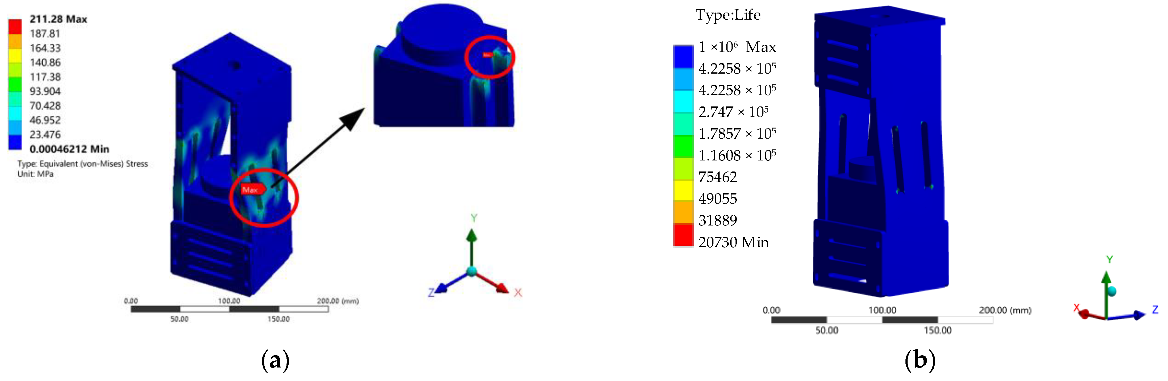
Under the maximum disassembly torque of 350 N·m, a static analysis was performed on the disassembly mechanism frame and impact housing assembly. The results of the analysis are shown in Figure 9.
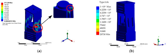
Figure 9.
Static simulation of the assembly and disassembly mechanism. (a) Equivalent stress contour map; (b) fatigue life contour map.
Under the ultimate torque, the maximum equivalent stress of the disassembly mechanism is 211.28 MPa, and the stress fatigue is 20730, respectively. The maximum equivalent stress is located at the root of the key on the impact housing. This stress value is within the yield stress of 6061-T6 aluminium alloy (275 Mpa). However, the safety factor in this design is 1.5. To improve the strength and service life of the disassembly mechanism during the disassembly and assembly process, it is proposed that the design parameters be optimized without significantly altering its mass.
3. Optimization of Key Structures
3.1. Design of Lightweight Optimization Plan for the Carrier Platform
According to the quality assessment in SolidWorks 2019 release, the carrier platform’s mass before optimization was 39.58 kg, accounting for about 50% of the machine’s target weight. To facilitate the transportation of the nut assembly and disassembly machine and handling by workers, a lightweight design for the carrier platform structure was developed based on the static analysis results. The weight reduction had the following optimization plans [31]:
- (1)
- The overall length and height of the carrier platform can be adjusted to make the structure more compact;
- (2)
- The material thickness and shape within the structure can be adjusted by replacing channel and square steel with angle steel.
3.2. Optimization of the Assembly and Disassembly Mechanism
The nut assembly and disassembly mechanism is connected through a movable pair formed by the four keys of the impact shell and the four grooves on the frame of the nut assembly and disassembly mechanism. The keys serve as the primary bearing parts for transmitting the reactive torque. The structure of the keys includes their thickness, chamfer radius, and width. A more accurate and efficient multi-parameter optimization method must be designed to achieve the strength and durability of the nut assembly and disassembly mechanism and to collaboratively optimize its multiple design parameters rather than adjusting a single parameter in isolation. The optimization design of the structural parameters of the nut assembly and disassembly mechanism is a multi-objective optimization problem.
3.2.1. Optimization Method Based on Kriging Model and NSGA-II Algorithm
The Kriging model [32] is an unbiased optimal interpolation approximation model. As a general response surface method, it can accurately predict the response of unknown data points and is suitable for solving complex engineering problems. As a global search technique, the non-dominated sorting genetic algorithm can find the optimal solution within the entire design space. By combining the Kriging model and the non-dominated sorting genetic algorithm, the design parameters of the nut assembly and disassembly mechanism can be optimized, ensuring model prediction accuracy while avoiding local optimal solutions.
The Kriging model predicts the value of an unknown point based on the spatial correlation of known sample points and can be represented as
In the formula, x represents the sample design points, y(x) is the response function, f(x) is the known function of x, and Z(x) is the variance function with a mean of 0. Its covariance is
In the formula, θk represents the model parameters, m is the number of predefined design variables, and dk is the Euclidean distance of the sample point k. Rk(θk, dk) is the correlation function with various forms, commonly including exponential, Gaussian, linear, and spline functions.
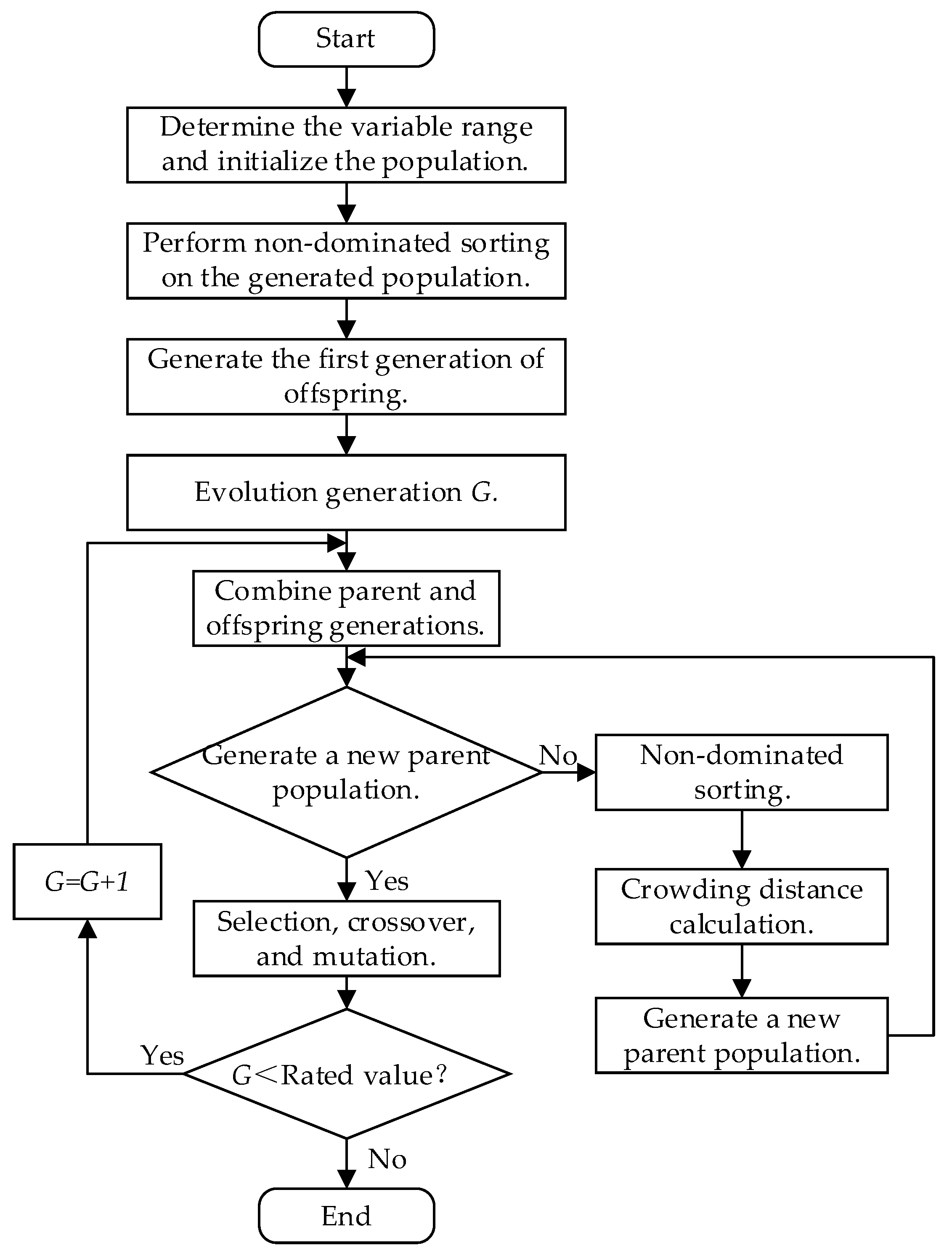
NGSA-II is a multi-objective optimization algorithm [33] that selects individuals through non-dominated sorting and crowding distance calculation. It considers all objectives during the optimization process and effectively avoids the phenomenon of solution clustering. The optimization process is as follows: a randomly initialized population is generated within the range of variable values. Non-dominated sorting is applied to all generated individuals, followed by selection, crossover, and mutation to create the first generation of the sub-population. The offspring and parent populations are merged, and non-dominated sorting is performed. The crowding distance of each individual in the non-dominated front is calculated, and appropriate individuals are selected to form the new parent population. The new parent population generates a new offspring population through operators. If the evolutionary generation requirements are met, the loop ends. Otherwise, the new parent and offspring populations are merged, non-dominated sorting and crowding distance calculations are performed, and the process repeats until the loop ends. The flowchart of this process is shown in Figure 10:
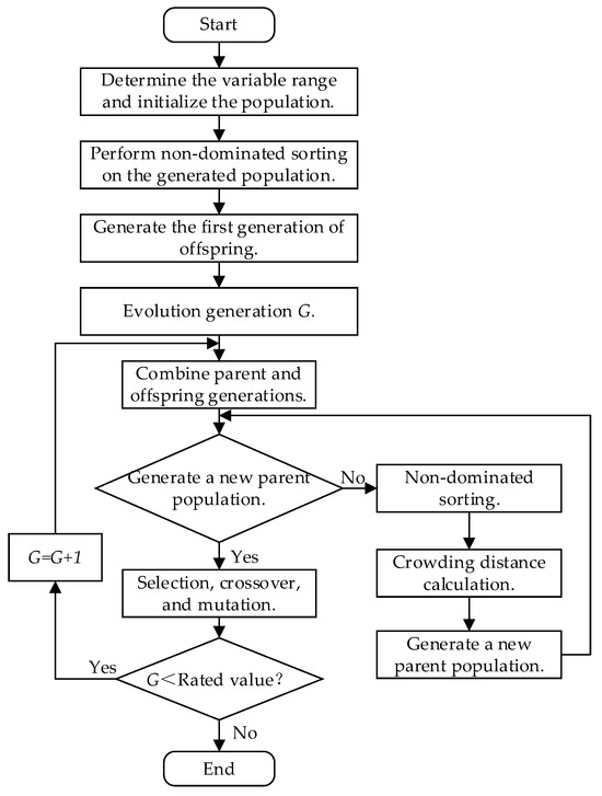
Figure 10.
NGSA-II algorithm flowchart.
3.2.2. Design Variables and Optimization Model
From the results of the static simulation in Section 2.3.2, it was known that the stress concentration point is located at the root of the key on the impact shell. To improve the nut assembly and disassembly machine’s structural strength and durability and avoid stress concentration, the chamfer radius A, width B, and thickness C of the key in the impact shell needed to be optimized. The optimization objectives were set as the maximum equivalent stress f1, total deformation f2, and stress fatigue life L. With the range of design variable values, mass, and yield stress as constraints, an optimization model for the design parameters of the impact shell was established as follows:
In the formula, δmax represents the maximum equivalent stress of the assembly and disassembly mechanism, and δ is the allowable value.
3.2.3. Responsive Surface Building
This study used the Optimal Space-Filling (OSF) experimental design method to generate 15 sample points [34]. The OSF experimental design is an optimization space-filling method based on specific criteria. This method aims to achieve the maximum understanding of the design space by evenly distributing design variables across the entire space with the minimum number of trials. The finite element analysis results of the maximum equivalent stress D and mass M for each sample point are listed in Table 3:
Table 3.
Design and results of motor housing structural optimization experiment based on the OSF method.
The fitting accuracy of the response surface model generated by the Kriging surrogate model is shown in Table 4. In the evaluation criteria, the best value for the coefficient of determination is 1, the best value for the root mean square error is 0, and the best values for the maximum relative residual, relative root mean square error, relative maximum absolute error, and relative mean absolute error are all 0. The response surface model meets the accuracy requirements and is suitable for subsequent multi-objective optimization.
Table 4.
Response surface fitting accuracy.
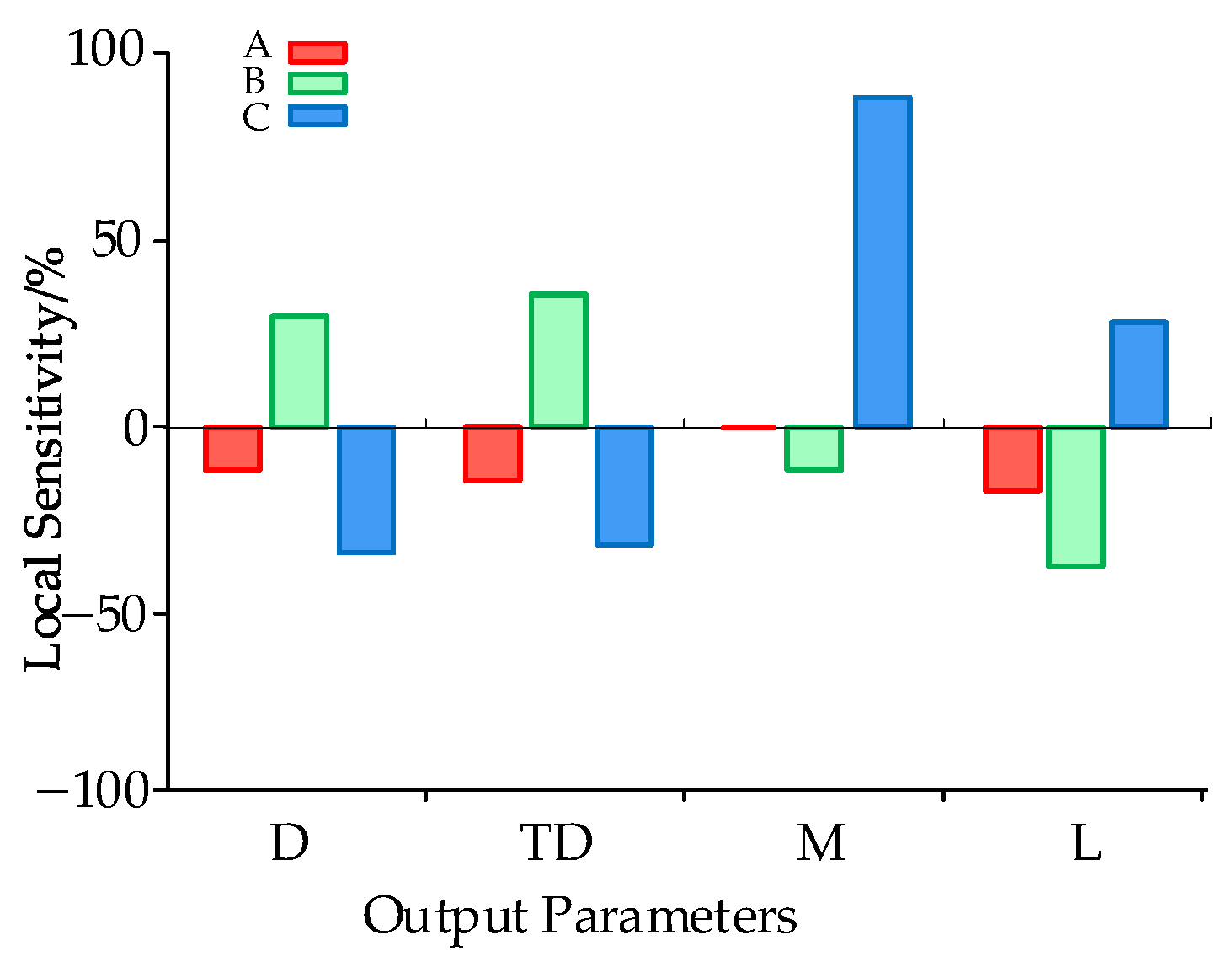
The sensitivity analysis of the design variables on the output variables is shown in Figure 11.
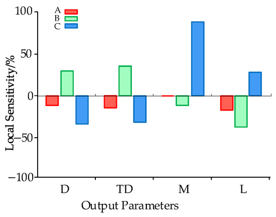
Figure 11.
Output variable sensitivity.
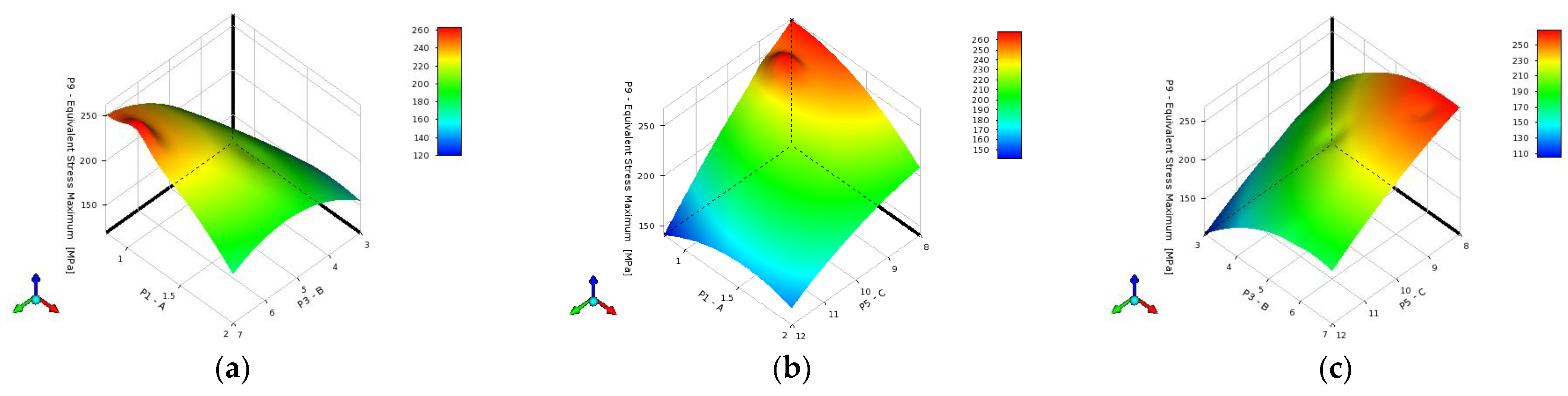
The maximum equivalent stress D of the assembly and disassembly mechanism is related to variables A, B, and C. The key slot width B positively correlates with D, and the key thickness C shows a higher significance. The thickness of the key has a positive correlation with mass and has a particularly significant impact. Fatigue life is negatively correlated with the key slot width B and chamfer radius A and positively correlated with the key thickness C. The impact of the optimized design parameters of the assembly and disassembly mechanism on the maximum stress D is shown in Figure 12.
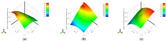
Figure 12.
Response surface of equivalent force D for different variable groups. (a) Response surface of the equivalence stress D for variables A and B; (b) response surface of the equivalence stress D for variables A and C; (c) response surface of the equivalence stress D for variables B and C.
4. Optimization Results and Experimental Testing
4.1. Optimization Results of the Carrier Platform
The length and height of the carrier platform structure were parameterized and modeled. In the Workbench software, the optimization goal is to minimize weight, with maximum stress and strain as constraints. The Screening tool optimizes the platform’s length and height directly. After optimization, the carrier platform’s height was 350.5 mm, and the length was 702.5 mm. The two columns of the platform were connected and reinforced with square steel. The height optimization reduced by 15%. A square steel bar could connect the two columns, while angle steel replaced the other low-load-bearing connection structures. The material thickness was reduced according to the steel specifications.
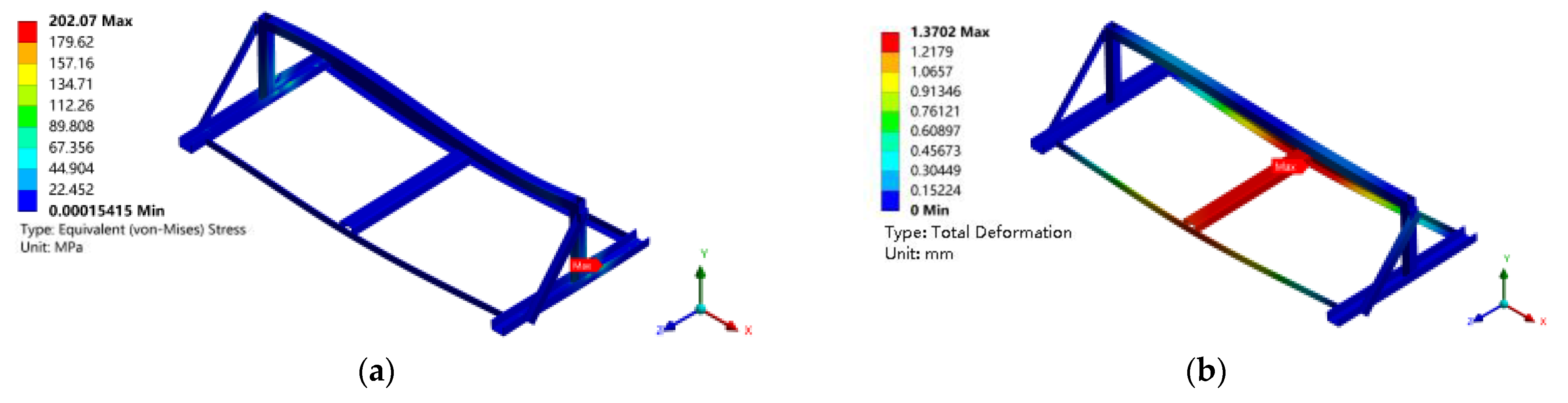
The static analysis of the optimized carrier platform structure under the same working conditions and constraints shows the maximum stress and strain distribution, as shown in Figure 13:

Figure 13.
Static simulation diagram of the optimized carrier platform. (a) Equivalent stress contour map; (b) T = total deformation contour map.
After optimization, the mass of the carrier platform decreased by 43.9%. Its maximum equivalent stress was 202.07 MPa, and the total deformation was 1.37 mm. The point of maximum equivalent stress was still located near the connection between the column and the bottom channel steel. The safety factor was 1.7, which meets the strength requirements.
4.2. Optimization Results of the Assembly and Disassembly Mechanism
The optimization solution settings are as follows: the population size was set to 100, the number of samples per iteration was 100, the maximum allowable Pareto percentage was 70%, the convergence stability percentage was 2%, the maximum number of iterations was 20, the mutation probability was 0.01, and the crossover probability was 0.98. The Pareto front is shown in Figure 14. The blue dot set represents results with good optimization.
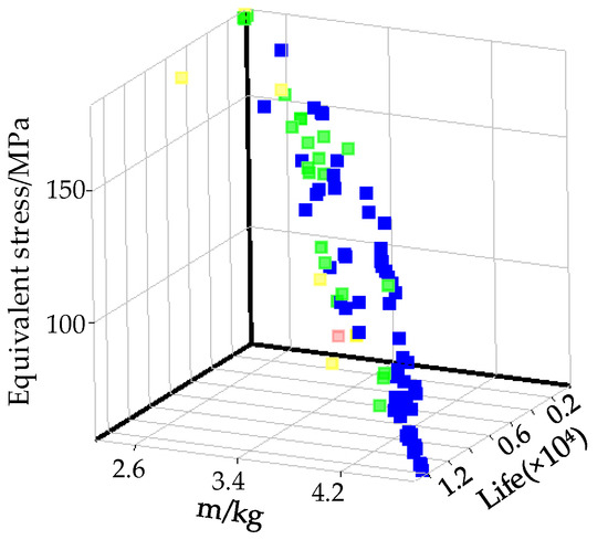
Figure 14.
Multi-objective optimization Pareto front.
As shown in Figure 15, the Pareto solution set distribution chart combines Kriging and the NGSA-II algorithm; it can be observed that as the mass increases, the maximum equivalent stress of the nut disassembly mechanism decreases, and the stress fatigue life increases. There is a direct contradiction between the objectives. Under the constraint of almost unchanged mass, three candidate solution sets were obtained by focusing on minimizing the maximum equivalent stress, as listed in Table 5. After comprehensive analysis, solution set 3 was selected as the optimal scheme. In this solution, the mass of the disassembly mechanism remained almost unchanged, the maximum stress value was reduced by 30.03%, and the fatigue life was increased by 3.7 times. Based on the optimization results, simulation calculations were carried out, and the equivalent stress distribution cloud diagram and the cycle count cloud diagram were obtained.
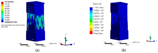
Figure 15.
Static simulation of the optimized assembly and disassembly mechanism. (a) Equivalent stress contour map; (b) fatigue life contour map.
Table 5.
Optimization results of the nut disassembly and assembly mechanism.
After the simulation optimization calculations, it was confirmed that the key load-bearing structures of the nut disassembly machine met the operational requirements. The equipment’s structural strength, stability, and safety were effectively ensured.
4.3. Transient Kinetic Analysis
The nut disassembly and assembly mechanism generates an impact when the nut is loosening, causing the structure to experience instantaneous vibration. However, under the damping effect, the vibration caused by the impact quickly decays. Nevertheless, the deformation caused by the impact may lead to a sudden failure of the structural strength.
The tightening mechanism transmits the torque from loosening the nut to the platform of the lifting mechanism (which is a cantilever plate), thereby inducing lateral vibrations in the entire robot frame. When the platform is subjected to an impact, its dynamic equation is as follows:
EJ(x) is the section’s bending stiffness, ω(x,t) is the transverse displacement, a function of section position x and time, t, ρ is the unit volume mass of the beam, and A(x) is the cross-sectional area of the beam.
Since the machinery is fixed between two railway tracks, its displacement and rotation are zero, while both ends are free. The bending moment at the ends is zero, and the shear force equals the impact load. In the absence of inertia effects, the boundary conditions are as follows:
P(t) is the impulse load, and Lhalf is the half-length of the transverse beam plate.
Since the location of the impact load does not coincide with the endpoint of the cantilever plate, the above equation can be expressed as
The cantilever plate can be considered to be subjected to an impulse load P(t), represented as
P0 is the impact force, which can be derived from the loosening torque, and t0 is the time during which the robot structure experiences the impact.
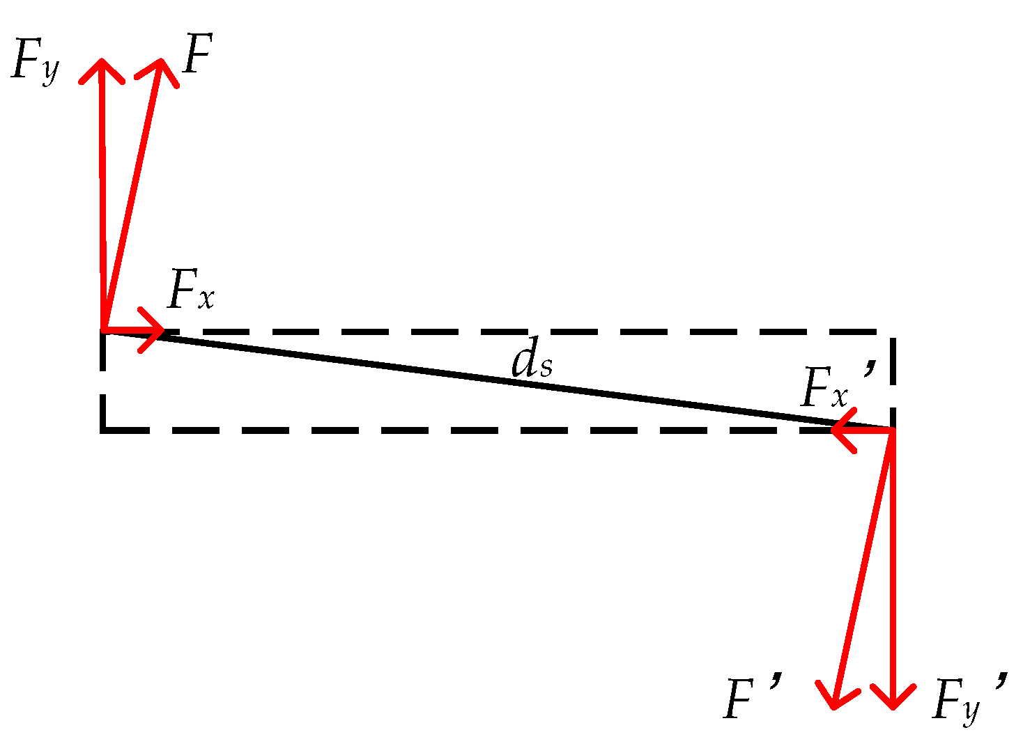
The forces acting on the cantilever beam are decomposed into components in the X and Y directions. The decomposition diagram is shown in Figure 16.
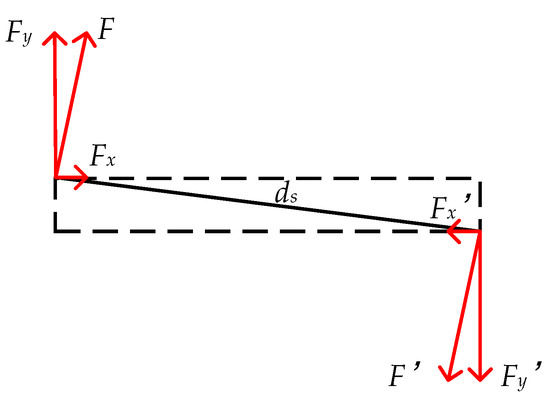
Figure 16.
Diagram of the force analysis of the cantilever square plate.
The maximum loosening torque is 350 N·m, and the length ds is 78.6 mm. Therefore,
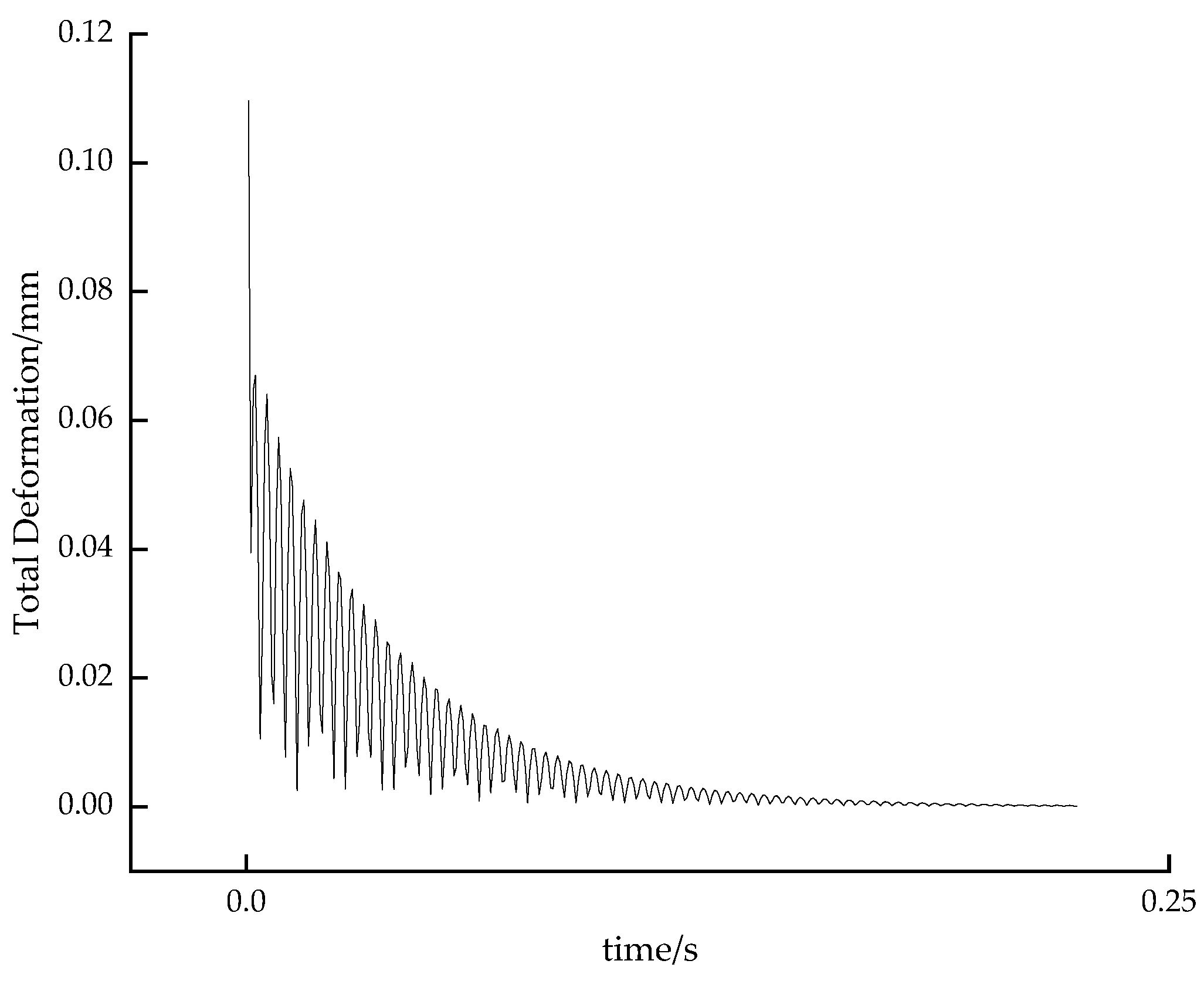
The damping ratio of steel is between 0.01 and 0.02, and here the value is 0.01. A transient simulation was conducted in Workbench. The transient displacement curve of the robot structure during loosening is shown in Figure 17.

Figure 17.
The total deformation of the machine is related to time.
According to the simulation results, the maximum transient deformation during loosening is 1.61 mm. Due to the damping effect, the displacement of the structure rapidly decays with time and eventually stabilizes, further indicating the reliability of the machine structure’s strength.
4.4. Experimental Testing
A success rate test of the nut’s sleeve fitting was conducted to verify the reliability and efficiency of the designed nut assembly and disassembly machine. This test checks its adaptability to position errors and deviations of the spiral track nails. Additionally, the efficiency is compared with the currently used double-head internal combustion wrench in the railway sector by comparing the time taken to disassemble tracks of the same length, thereby validating its high efficiency.
4.4.1. Workflow
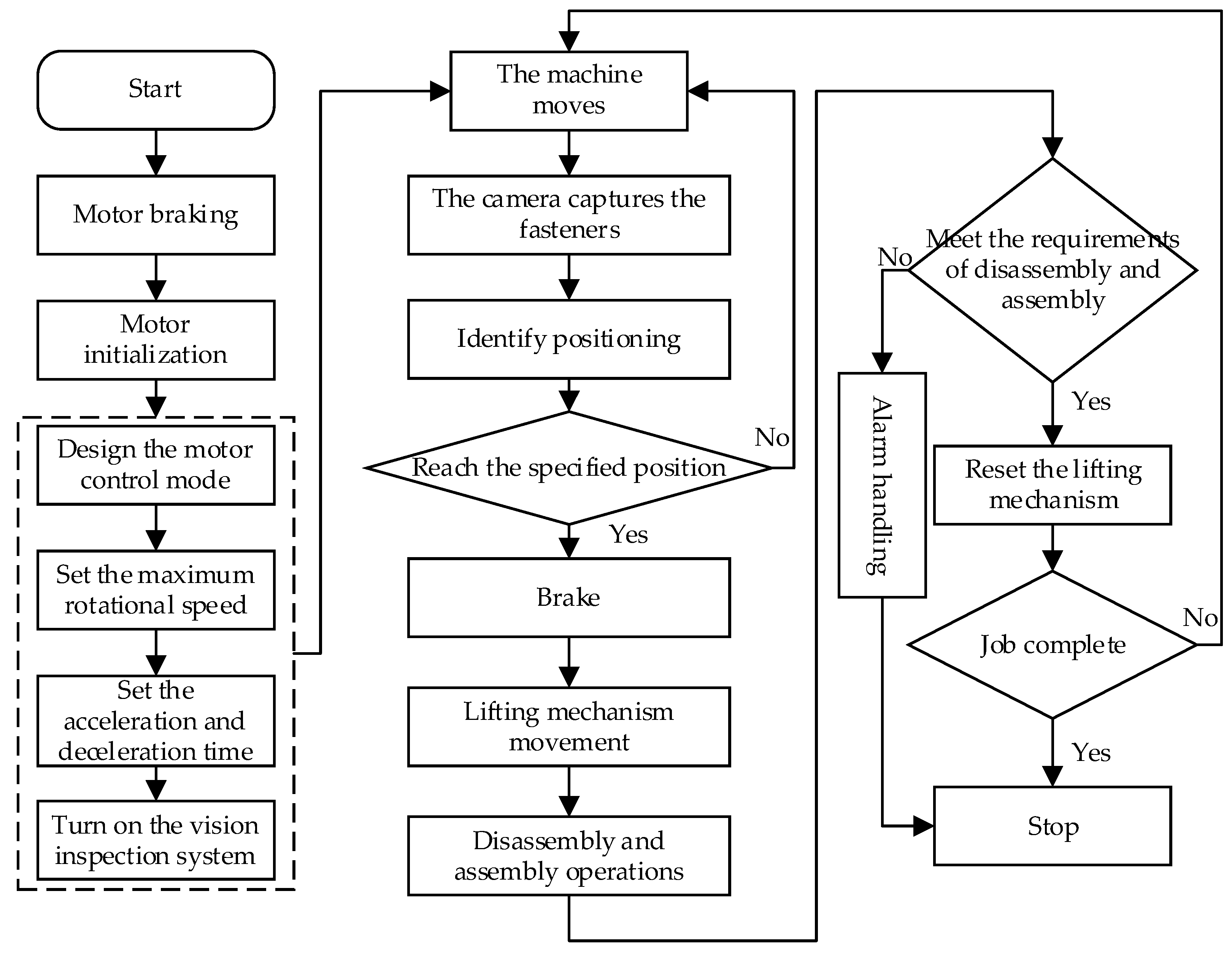
Under the premise of ensuring operational safety, this study is based on the Visual Localization Method for Fastener-Nut Disassembly and Assembly Robot Based on Improved Canny and HOG-SED [28], and the workflow is shown in the following Figure 18.
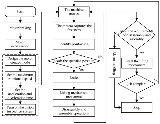
Figure 18.
The workflow of the nut disassembly machine.
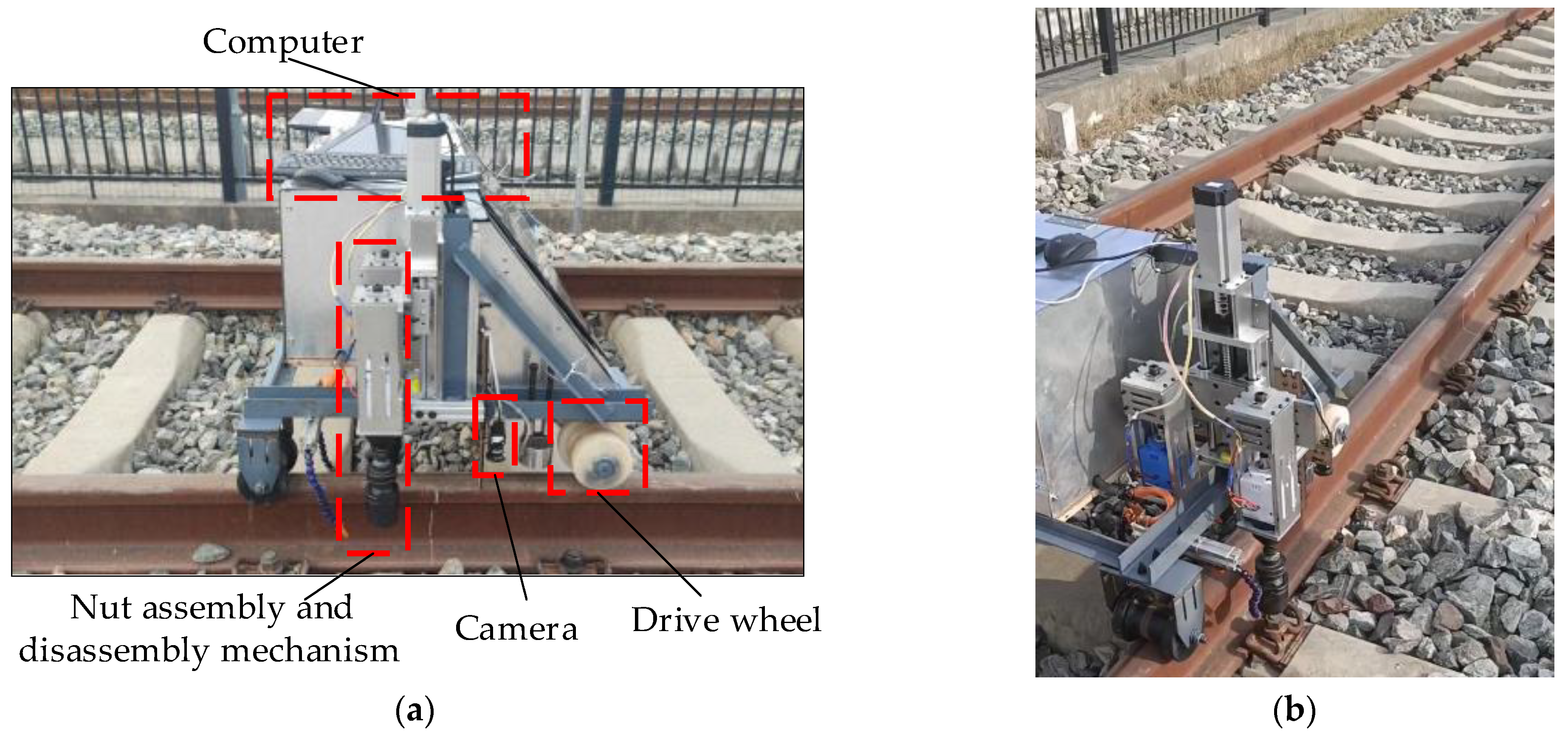
The experimental prototype was built for functional testing on the ballasted track at the Xi’an Locomotive Depot, which is a straight track with a length of more than 100 m and a gauge of 1435 mm with a slope of less than 10 thousandths; the prototype and the operational site environment are shown in Figure 19.
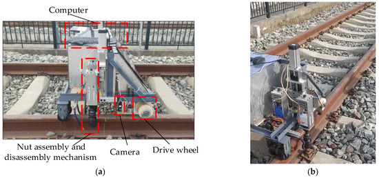
Figure 19.
Photo of the experimental testing. (a) Nut disassembly and assembly machine prototype; (b) experimental railway track.
4.4.2. Nut Insertion Rate Test
The test of the sleeve’s alignment accuracy with the nut under good lighting conditions is shown in Table 6. The average nut insertion rate from three trials was 94.7%, demonstrating the reliability of the designed nut disassembly equipment.
Table 6.
Socket sleeve nut test results.
4.4.3. Disassembly and Assembly Performance Experiments
The nut assembly and disassembly function was validated based on the technical requirements. According to the identification and positioning algorithm, considering factors such as lighting, fastener corrosion, and oil contamination, the machine’s recognition success rate is 98%. The disassembly mechanism was set to achieve an output torque of 350 N·m after 6 s of operation. A disassembly experiment uses the rated disassembly torque, disassembling 30 sets of fastener nuts. The disassembly experiment results are listed in Table 7.
Table 7.
The repeated experiment of nut removal.
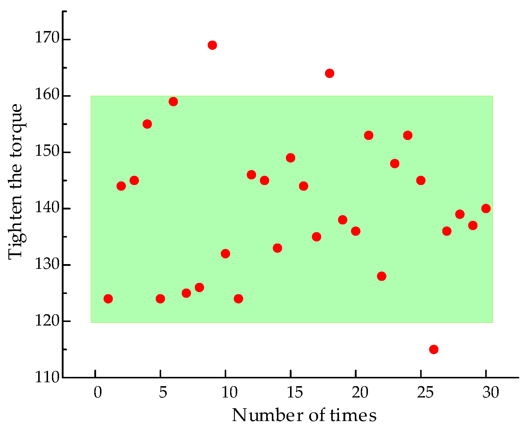
The tightening torque of the nuts was 140 ± 20 N·m. The nut disassembly mechanism reached an output torque of 140 N·m in approximately 4.3 s. After tightening, a torque wrench was used to measure the tightening torque. The results of the tightening torque test are shown in Figure 20.

Figure 20.
Scatter plot of nut-tightening experimental results.
The results from multiple experiments indicate that, within the 6 s timed and fixed-speed control, the nut disassembly success rate is 96.7% for the 30 sets of fasteners, effectively achieving nut disassembly. The machine can tighten the nut within the range of 140 ± 20 N·m with an average time of 4.3 s, achieving a tightening success rate of 90%. The machine meets the technical requirements for fastener nut assembly and disassembly operations.
4.4.4. Disassembly and Assembly Efficiency Analysis
According to the “General Technical Conditions for Rail Tie Bolt Wrench” for equipment functionality testing, a torque wrench was used to measure the torque of the nut disassembly. First, the nut was tightened to 350 N·m using the torque wrench, and then the designed nut disassembly equipment was used for removal. The disassembly was carried out continuously for three sets, with each set of straight tracks being 100 m long (approximately 680 nuts). The disassembly time was compared with that of the onsite internal combustion wrench, and the results are listed in Table 8.
Table 8.
Comparison of disassembly time for the same nuts.
The designed machine was compared with the current disassembly equipment, and the time spent disassembling and assembling nuts on the same track length was reduced by approximately 42.4%. This significant time-saving indicates a marked improvement in fastener maintenance efficiency, demonstrating the effectiveness of the new design in optimizing railway maintenance processes.
5. Conclusions
This study designed a railway fastener nut assembly and disassembly machine to address the high labor intensity and inefficiency issues in the maintenance and laying of railway fastener nuts. It conducted a study on its structure, leading to the following conclusions:
- (1)
- Through the linear railway fastener nut assembly and disassembly operations and environment, this paper proposes a parallel quad-manipulator nut assembly and disassembly machine capable of adapting to deviations and positional errors of track spikes, capable of disassembling and assembling all nuts on a single sleeper simultaneously;
- (2)
- Using the ANSYS Workbench simulation platform, a finite element analysis of the key structures of the railway fastener nut assembly and disassembly machine was conducted. Based on the results of static analysis, the structure of the machine was optimized, including the lightweight design of the transport platform through empirical optimization methods and direct optimization. Based on the Kriging surrogate model and non-dominated sorting genetic algorithm, the design parameters of the nut assembly and disassembly mechanism were optimized to enhance its strength and durability;
- (3)
- The optimal mass solution within the dimensional constraints of the transport platform and the Pareto optimal solution set of the optimization objective functions for the nut assembly and disassembly mechanism were obtained, and option 3 was selected among the three proposed options. The optimized transport platform had a mass reduction of 43.9% while meeting strength requirements; the maximum stress of the optimized nut assembly and disassembly mechanism was reduced by 30.03%, and the fatigue life was increased by more than 3.7 times, significantly enhancing the structural performance of the railway fastener nut assembly and disassembly machine. The transient dynamic analysis of the impact vibration caused by the instant removal of a large torque nut shows that the maximum deformation under extreme conditions is 1.61 mm. Due to the damping effect of the structure, the deformation decreases over time and eventually stabilizes, further validating the strength of the machine structure;
- (4)
- Based on the design, a prototype of the railway fastener nut assembly and disassembly machine was constructed and field-tested on standard tracks at the Xi’an Locomotive Depot. The results show that the designed machine can achieve automatic and efficient disassembly and assembly of fastener nuts, saving 42.4% of operation time compared to a double-head internal combustion wrench, enhancing the efficiency of fastener assembly and disassembly, and playing an important role in advancing intelligent railway maintenance work and its application value.
However, in ballasted track environments, if stones cover fasteners, the machine cannot perform nut assembly and disassembly operations; although the modifications in size and the universal joint sockets have reduced the incidence of nut jamming, it cannot entirely prevent it, highlighting the limitations of this machine’s operation in complex environments.
Author Contributions
Conceptualization, G.C. and X.C.; Methodology, G.C.; Software, G.C. and J.Z.; Validation, G.C., M.Z., P.W. and X.W.; Formal analysis, G.C.; Investigation, G.C. and M.Z.; Resources, G.C. and X.C.; Data Curation, G.C.; Writing—Original Draft Preparation, G.C., P.W. and X.W.; Writing—Review and Editing, G.C., X.C. and X.W.; Visualization, M.Z.; Supervision, X.C.; Project Administration, G.C. and X.C.; Funding Acquisition, X.C. and P.W. All authors have read and agreed to the published version of the manuscript.
Funding
This research was funded by the Shaanxi Provincial Natural Science Basic Research Program (2023-JC-YB-362), the Natural Science Research Project of the Department of Education of Shaanxi Province (23JK0548), and the Key Research and Development Program of Shaanxi Province (2024GX-YBXM-524).
Data Availability Statement
The datasets presented in this article are not readily available because they are part of an ongoing study, and it requires significant time and labor to collect data in the railway engineering section. Requests to access the datasets should be directed to cao_xust@sina.com.
Acknowledgments
The author would like to thank the Xi’an Bureau of China National Railway for providing the experimental site and project experience. In addition, the authors express their gratitude to the editors and anonymous reviewers for their constructive comments and valuable suggestions.
Conflicts of Interest
The authors declare no conflicts of interest.
References
- Duan, B.X.; Chen, Q.F.; Guo, W.H. Influence of rail fastener failure status on the bridge on the dynamic response of train bridge system. J. Railw. Sci. Eng. 2024, 1–13. [Google Scholar]
- Yan, Z.Q.; Sun, L.L.; Xiao, J.H. Experimental study on mechanical properties of 60Si2Mn spring steel for railway fastener clips. J. Railw. Sci. Eng. 2023, 20, 127–135. [Google Scholar]
- Hu, L.J.; Yang, J.Z.; Lin, H.S. Research on the Rail Fastening Design and Its Derivation Process. J. Railw. Eng. Soc. 2018, 35, 32–37. [Google Scholar]
- Gao, L.; Zhao, W.Q.; Hou, B.W. Research on vertical mechanical behavior of WJ-8 fastener under clamping force failure. Eng. Mech. 2020, 37, 228–237. [Google Scholar]
- Sun, L.L.; Fang, H.W.; Ran, L. Stress Analysis of Screw Spike in Type II Fastening System. Railw. Eng. 2019, 59, 129–133. [Google Scholar]
- Han, Q.; Wang, S.; Fang, Y.; Wang, L.; Du, X.; Li, H.; He, Q.; Feng, Q. A Rail Fastener Tightness Detection Approach Using Multi-source Visual Sensor. Sensors 2020, 20, 1367. [Google Scholar] [CrossRef] [PubMed]
- Liu, J.W.; Liu, H.L.; Ma, Z.J. Three-stage Advancement Location Method for Center of Railway Fastener. Nut. J. China Railw. Soc. 2021, 43, 102–107. [Google Scholar]
- Holder, D.E.; Csenge, M.V.; Qian, Y. Laboratory investigation of the ski-style fastening system’s performance under heavy haul freight railroad loads. Eng. Struct. 2017, 139, 71–80. [Google Scholar] [CrossRef]
- Pan, Y.X.; Wang, M.; Zhang, S.S. Research and Analysis on the Improvement Design of Railway Internal Combustion Bolt Wrench Based on Ergonomics. Machinery 2018, 45, 52–58. [Google Scholar]
- Department of Track, Transportation Bureau of China Railway Corporation. Railway Track Engineering Technical Manual; China Railway Publishing House: Beijing, China, 2016; pp. 346–352. [Google Scholar]
- Gao, H.Z. Study on the calculation method of the fastener nut’s critical rust thickness. J. Mach. Des. 2021, 38, 22–26. [Google Scholar]
- Miao, B.G.; Zhang, W.H.; Liu, J.X. Review on frontier technical issues of intelligent railways under Industry 4.0. J. Traffic Transp. Eng. 2021, 21, 115–131. [Google Scholar]
- Wang, Y.J.; He, D.Y. Interval Analysis of Spike Bolt Position Error Parameters. J. Mech. Eng. Autom. 2023, 3, 124–126. [Google Scholar]
- Zhang, W.; He, F.M.; Fan, S.J. Research on the development of ballastless track fastener bolt wrench. In Proceedings of the 2008 Academic Symposium on Public Works Machinery Equipment and Application Innovation, Xiangfan, China, 24 September 2008; Volume 11, pp. 91–93. [Google Scholar]
- Chen, X.J. Design of impulsive device of automatic sleeper bolts oiling equipment. Mach. Des. Manuf. 2009, 5, 56–58. [Google Scholar]
- Liu, C.; Zhang, R.; Wang, P. Research on Fastener Mechanized Removal Equipment for High Speed Railway. Railw. Eng. 2022, 62, 45–47. [Google Scholar]
- Zhang, D.; Li, X.; Zhang, Q. Research and engineering application of layout optimization for lockbolt structures in railway wagons considering multidimensional failure modes based on MSNSGA-III. Sci. Rep. 2024, 14, 19557. [Google Scholar] [CrossRef]
- Liu, C.; Ye, T.G.; Shi, L.Q. The structural optimization of torque sensor based on response surface method and genetic algorithm. J. Harbin Eng. Univ. 2025, 9, 1–11. [Google Scholar]
- Li, H.; Wang, Y.; Ma, Y.S. Research on structural optimization design for powder separator of large vertical mill based on Kriging model. J. Eng. Des. 2024, 31, 801–809. [Google Scholar]
- Zheng, Y.Q.; Wang, S.M.; Wang, Y.P. Fatigue life prediction for a truck crane boom based on stress and strain life prediction models. J. Mech. Strength 2013, 35, 850–854. [Google Scholar]
- Zhu, Q.Y.; Zhao, Y.L.; Chen, Y.G. Fatigue crack retardation by the application of hard damping coating to blades under resonance. J. Cent. South Univ. 2023, 30, 1095–1106. [Google Scholar] [CrossRef]
- Huang, J.; Lu, W.T.; Chen, J.R. Modeling and vibration performance analysis of a ball screw vertical lifting system. Manuf. Technol. Mach. Tool. 2022, 2, 151–158. [Google Scholar]
- Fan, J.F.; Huang, S.C.; Mei, E.Z. Motion and simulation analysis based on the cross shaft’s universal joint coupling. J. Mach. 2021, 38, 91–96. [Google Scholar]
- Jiang, J.F.; Bi, Y.B. Design of robotic end effector for hi-lock nut automated installation. Manuf. Technol. Mach. Tool 2019, 8, 73–76. [Google Scholar]
- Meng, W.; Zhang, B.P.; Zhao, D.Q. Automated holding and screwing mechanism for bolts. Tsinghua Sci. Technol. 2000, 8, 57–60. [Google Scholar]
- Jiang, Y.; Huang, Z.; Yang, B.; Yang, W. A review of robotic assembly strategies for the full operation procedure: Planning, execution and evaluation. Robot. Comput.-Integr. Manuf. 2022, 78, 102366. [Google Scholar] [CrossRef]
- Wang, W.; Yu, W.P.; Li, X.F. Research and Mechanism Design of Rigid Docking Applied for Multi-dimension Position/Orientation Offset. Acta Aerodyn. Sin. 2010, 31, 1872–1879. [Google Scholar]
- Cao, X.; Zuo, M.; Chen, G.; Wu, X.; Wang, P.; Liu, Y. Visual Localization Method for Fastener-Nut Disassembly and Assembly Robot Based on Improved Canny and HOG-SED. Appl. Sci. 2025, 15, 1645. [Google Scholar] [CrossRef]
- Liu, G.Z.; Guan, D.Z.; Shi, L. Finite element analysis and optimization design on special forging mechanical arm. Forg. Stamp. Tech. 2024, 49, 160–165+178. [Google Scholar]
- Guo, H.D.; Zhang, L.H.; Yang, Y. Design and finite element analysis of parallel quadruped robot. J. Mach. Des. 2024, 41, 51–57. [Google Scholar]
- Chen, F.M.; Zhu, E.X.; Wei, S.P. Design and Analysis of Leg Structure of A Novel Wheeled-legged Robot. Mech. Sci. Technol. 2023, 1–15. [Google Scholar]
- Wang, G.H.; Wang, Q.L.; Wu, M.P. Dynamic Analysis and Response Surface Optimization of Pipe Winch Barrel. Mech. Sci. Technol. 2023, 42, 1592–1601. [Google Scholar]
- Yang, H.B.; Shi, W.K.; Chen, Z.Y. Multi-objective optimization of macro parameters of helical gear based on NSGA-II. J. Tsinghua Univ. Sci. Technol. 2023, 53, 1007–1018. [Google Scholar]
- Wang, L.; Wang, S.J.; Ma, S. Parametric Design and Optimization of Multi-material Mixing Screw Structure by CFD. Mech. Sci. Technol. 2023, 1–12. [Google Scholar]


Disclaimer/Publisher’s Note: The statements, opinions and data contained in all publications are solely those of the individual author(s) and contributor(s) and not of MDPI and/or the editor(s). MDPI and/or the editor(s) disclaim responsibility for any injury to people or property resulting from any ideas, methods, instructions or products referred to in the content. |
© 2025 by the authors. Licensee MDPI, Basel, Switzerland. This article is an open access article distributed under the terms and conditions of the Creative Commons Attribution (CC BY) license (https://creativecommons.org/licenses/by/4.0/).