Abstract
As a key component of the die-casting machine, the flow linearity of the high-pressure, large-flow proportional throttle valve is a critical factor affecting injection accuracy at low openings. However, under existing main valve structures, flow linearity is typically nonlinear. To address this issue, this paper introduces a main valve structure designed to enhance flow linearity at low openings. Firstly, the working principle of the proportional throttle valve is explained, and the relationship between flow rate and spool displacement is calculated. Secondly, a finite element model of the proportional throttle valve’s main valve flow field is developed. The impact of four primary spool structures on flow linearity is examined, and a small rounded rectangular throttle orifice is proposed. Thirdly, the size of the spool orifice is optimized using an orthogonal test method, and the trend of how different structures’ orifice sizes influence flow linearity is investigated. Finally, a valve prototype is fabricated, and the optimization’s effectiveness is experimentally verified. The results of the throttle valve’s design and optimization provide guidance for future work.
1. Introduction
As a typical electrohydraulic system in the key components, the high-flow cartridge electro-hydraulic servo-proportional throttle valve plays an important and significant role in many working conditions [1,2,3], especially in the field of aviation, aerospace, communication, and industrial machinery [4]. One of its typical application scenarios is in the injection system of die-casting machine.
Given the profound influence of injection speed and pressure on casting quality, it is necessary to use different injection speeds and pressures for specific workpieces and molds to enhance the quality of casting and reduce porosity. Consequently, the adjustment of these parameters must be approached with a keen understanding of the particulars of injection speed and pressure. This calls for the development of a proportional throttle valve that can withstand high pressure and facilitate a large flow rate while also demonstrating rapid response times and exceptional flow regulation capabilities. Simultaneously, the flow characteristics of the throttle valve and the degree of linearity between the value’s opening percentage are collectively referred to as flow linearity. A higher degree of flow linearity correlates with more precise control performance, which in turn is influenced by the structure of the spool throttle port. Therefore, a detailed examination of the spool throttle port within the proportional throttle valve is essential to inform the optimization of value design for enhanced performance.
The study of valve flow has been a subject of interest for many researchers, with a particular focus on the impact of various structural designs on flow characteristics. For the bidirectional proportional throttle valve, Xie [5] discussed the influence of the inclination angle, width, and initial overlap height of the chute and rectangular groove on the flow response of the valve. Zhang [6] proposed a method of a multi-stage proportional directional valve throttling groove, which was optimized by artificial neural network model and genetic algorithm. Ma [7] proposed a linear throttling groove structure, which can achieve a regular linear relationship between valve port flow and spool displacement. Wang [8] pointed out that the output flow of the proportional throttle valve is not only related to the type of valve port but also affected by the working pressure difference. Liu [9] studied the influence of the design parameters of the proportional throttling cartridge valve by the root locus method and selected several parameters that have a greater impact on the performance. Then, the optimization based on iterative eigenvalue configuration is realized. After optimization, the performance of the valve is effectively improved. Xu [10] studied the exhaust volume under different inlet and outlet pressure differences, inlet valves, and throttle areas through simulation and verification experiments. The results show that the square of the flow rate is proportional to the pressure difference, and the resistance coefficient is linear with the reciprocal of the throttle area and the flange area. In order to improve the flow linearity of the proportional valve under open-loop control, Zhang [11] achieved this by optimizing the proportional electromagnet in the valve and compensating the feedforward control device. Zhang [12] proposed a new type of two-position three-way hydraulic proportional valve suitable for high-pressure and high-flow conditions, established a simulation model of the new type of proportional valve, investigated the motion relationship between the pilot stage and the main stage, and analyzed the influence of the structural parameters on the stability. Yao [13] developed a 70 MPa bi-directional proportional cartridge valve. The finite element model of the valve was established with the nominal diameter of 25 mm cartridge valve as the research object. The valve port flow was calculated and tested, and the results showed that the valve flow control accuracy is high. Liu [14] proposed a new type of digital flow control valve. The influence of structural parameters, such as the spool diameter, spring stiffness, and damping hole diameter, on the stability of flow regulation is studied. Genetic algorithms have been used to optimize the key parameters that affect the stability of the valve flow to determine the best parameters. Gao [15] proposed a new two-stage proportional valve with pilot digital flow distribution. The influence of structural parameters (fixed orifice diameter and main valve spring) on the motion of the main valve is analyzed. In addition, when optimizing the fixed orifice diameter, a new design criterion considering maximum pressure sensitivity, flow controllability, and flow linearization is proposed to improve the balance between effective displacement and displacement fluctuation of the main valve. Han [16] proposed the optimization of the geometric shape of the lifting valve groove to reduce the axial flow force. The numerical simulation method is used to obtain the visualization of the internal flow and to better understand the flow field in the valve with double U-grooves. Avram [17] analyzed various versions of hydraulic devices found in the structure of proportional hydraulic equipment. For each version, the author establishes the change rule of the flow section according to the position of the regulating element relative to the reference position. This method is very useful when the theoretical analysis of the proportional device is needed and when the characteristic diagram of the device is theoretically established. Tan [18] proposed a method to reduce the steady-state axial flow force acting on the main spool of the split-tube proportional valve. In Meng’s work [19], the effects of key structural parameters such as the initial height of the overlap region, the width of the high-pressure and low-pressure holes, the radius of the magnetic force, the coupling pitch angle of the magnetic levitation, the length of the sensitive cavity and the system pressure on the dynamic response were studied. Zhang [20] proposed a parametric mathematical model of the coupling throttling effect of the directional valve. The model uses three basic throttling topologies (O-type, U-type, and C-type) to form a topologically variable space.
The current research focuses on the proportional throttle valve spool throttle port, which primarily concerns flow characteristics. However, there is a paucity of studies exploring the relationship between the structure of the flow under investigation and the degree of linearity in opening variation. In this paper, a new type of spool orifice structure (small rounded rectangle) is proposed to improve the flow linearity of the main valve at a small opening. The flow characteristics of four orifice structures (triangle, sector, rounded rectangle, small rounded rectangle) are analyzed by a finite element flow field simulation, and the key structural parameters (such as length, rounded radius, inclination angle, etc.) are optimized by the orthogonal test method to determine the optimal size combination. Finally, a sample valve is processed and tested to verify the effectiveness of the optimized structure, which provides a valuable reference for the subsequent design of the throttle valve.
2. Working Principle
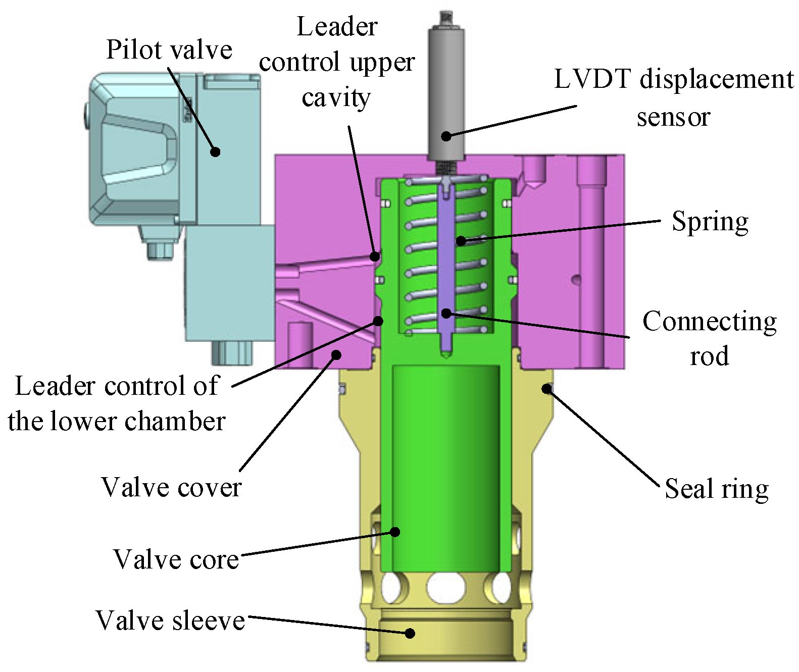
The operational principle of the high-pressure high-flow proportional throttle valve is illustrated in Figure 1.

Figure 1.
Structure of high-pressure and large-flow proportional throttle valve.
The selection of the pilot valve for an electro-hydraulic servo-proportional valve involves the spool and the valve cover forming between the two pilot control chamber. The pilot level electro-hydraulic servo-proportional valve manages the flow of fluid in and out of these chambers. Thus, it changes the pressure levels in upper and lower chambers of the pilot control, resulting in a difference in pressure, which in turn control the spool up and down action of the main valve.
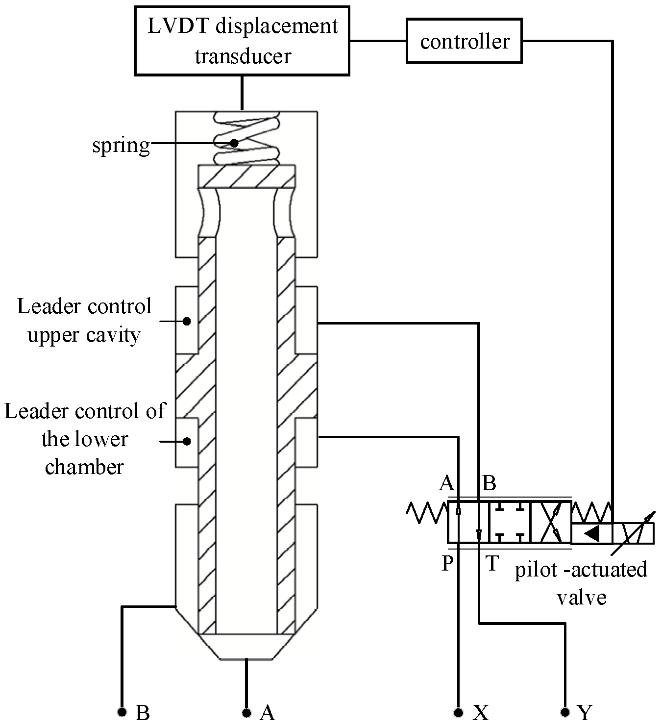
As shown in Figure 2, the position of the spool is transmitted through the LVDT (Linear Variable Displacement Transducer) displacement sensor to the controller, where it is processed and converted into an output signal for the pilot control valve. This process established a closed-loop control system for the displacement of the proportional throttle valve’s spool. The opening of the main valve spool of a proportional throttle valve causes a variation in the flow rate. By controlling the main valve spool position and subsequently regulating the proportional throttle valve output flow size, it is possible to achieve the desired control of the flow rate. A is the oil inlet of the main valve, B is the oil outlet of the main valve, X is the oil inlet of the pilot valve, and Y is the oil outlet of the pilot valve. P is the oil inlet of the three-position four-way directional control valve, and T is the oil outlet of the three-position four-way directional control valve.

Figure 2.
The schematic diagram of the principle of the high-pressure large-flow proportional throttle valve.
Table 1 presents the primary parameters of the proportional throttle valve. The primary factors influencing flow linearity include the pressure difference before and after the throttle valve, the shape and size of the orifice, the properties of the fluid, the internal leakage of the throttle valve, and some other external disturbances [21]. Enhanced flow linearity performance can improve the stability and reliability of the system and reduce the impact of flow fluctuations on it. Moreover, it can also reduce energy consumption and maintenance costs as well as further optimize the operational efficiency of the system and improve control accuracy and stability. Thus, a theoretical analysis is conducted.

Table 1.
Throttle valve parameter index table.
The flow rate of the main valve spool port of the proportional throttle valve is calculated according to the flow formula of the fluid through the submerged orifice. The expression is as follows:
where q represents flow through the main valve spool port (L/min); Cd represents the valve port flow coefficient; Az represents the main valve spool port overflow area (mm2); ρ represents the fluid density (kg/m3); and Δp represents the main valve spool inlet and outlet before and after the pressure difference (MPa).
There is a linear relationship between the valve port flow area A and the valve opening:
where A(x) is the valve opening area, A0 is the initial port flow area, k is the coefficient between the flow area and the opening degree, and x is the opening degree. Equation (2) is substituted into the flow formula:
Ideally, the flow Qideal should have a linear relationship with the opening x:
The difference between the actual flow Q (x) and the ideal flow Qideal(x) is expressed as follows:
Compare the actual flow with the ideal flow:
where Cd is the flow coefficient of the valve port, reflecting the correction of the actual flow by factors such as the shape of the flow channel and the viscosity of the fluid. A0 + kx is the flow area of the valve port changes linearly with the opening x, where A0 is the initial area (the area when the opening is zero) and k is the area change rate. is shown that the flow rate is proportional to the square root of the pressure difference ΔP and inversely proportional to the square root of the fluid density ρ. kidealx represents the ideal linear flow model; that is, the flow is proportional to the opening x, and the proportional coefficient is kideal. ΔQ(x) is the difference between the actual flow and the ideal flow. The goal of optimization is to minimize ΔQ(x) by adjusting A0 and k so as to improve traffic linearity. By adjusting A0 and k, ΔQ (x) can be minimized to optimize the linearity.
The theoretical analysis found that flow linearity is significantly influenced by the structure of the spool port. Therefore, the flow field simulation of four spool port structures was carried out, with a particular focus on the linearity of the throttle valve’s flow at small openings. Small openings are typically defined as those in the range of 5~20%. Based on the above simulation results, the optimal structure and size are designed.
3. Simulation and Optimization
3.1. Main Valve Spool Force Analysis
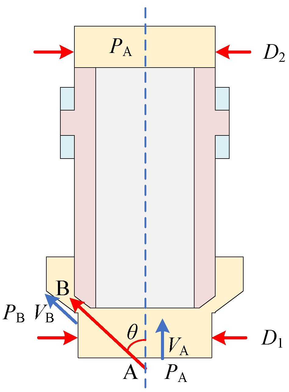
Hydrodynamic force refers to the force generated by the reaction of the fluid flow in the valve port and the valve cavity to the valve core due to the change of momentum. It is a kind of fluid force. The fluid force will affect the control force of the valve core, cause the self-excited vibration of the valve, and then affect the stability of the system. Therefore, the research on the fluid force of the main valve spool of the proportional throttle valve was carried out. Before the hydrodynamic analysis of the main valve spool, the following assumptions were made: (1.) The pressure of the upper chamber of the main valve spool is equal to the pressure of the lower chamber, both of which are PA (2.) regardless of the friction in the process of oil flow. (3.) It belongs to the steady, incompressible fluid, and the density of the oil does not change with space and time. (4.) Regardless of the control of the body oil gravity, the oil flow direction flows from the main valve spool A to the main valve spool B through the spool throttle port, and the angle between the oil flow direction of the valve port and the spool axis is the jet angle θ. The schematic diagram of the flow force analysis model of the main valve spool of the proportional throttle valve is shown in Figure 3.

Figure 3.
Schematic diagram of hydraulic dynamic analysis model for proportional throttle main valve spool.
Taking the axis of the main valve spool upward as the positive direction, it can be obtained from the momentum theorem:
where PA is the pressure at the lower chamber A of the main valve spool (MPa), D2 is the diameter of the upper chamber of the main valve spool (mm), D1 is the diameter of the lower chamber of the main valve spool (mm), Fv is the force applied to the hydraulic oil by the main valve spool (N), ρ is the density of the hydraulic oil (kg/m3), Q is the flow rate of the hydraulic oil (m3/s), VA is the speed of the hydraulic oil at the main valve spool port A (m/s), VB is the speed of the hydraulic oil at the main valve spool port B (m/s), and θ is the jet angle of the hydraulic oil (°).
It can be obtained that the force applied by the hydraulic oil to the main valve spool is as follows:
also taking into account the following:
where A(xp) is the flow area (mm2) of the orifice of the main valve spool when the opening is xp and AA is the flow area (mm2) of the lower chamber A of the main valve spool.
Bringing Formula (9) into Formula (8), we can derive the following:
The main valve spool of the proportional throttle valve is also subjected to the following forces: the driving force of the oil pressure in the upper and lower chambers of the main valve spool control chamber on the main valve spool, the viscous damping force of the oil on the main valve spool, the spring force of the spring on the main valve spool, the friction force of the sealing ring and the wall on the main valve spool, etc. The opening direction of the main spool is defined as the positive direction. According to Newton’s second law, the dynamic equation of the main spool of the proportional throttle valve is as follows:
where mt is the mass of the main valve spool (kg), Bp is the viscous damping coefficient of the main valve spool [N/(m/s)], K is the spring stiffness (N/mm), and Ff is the friction force of the main valve spool (N).
3.2. Modeling
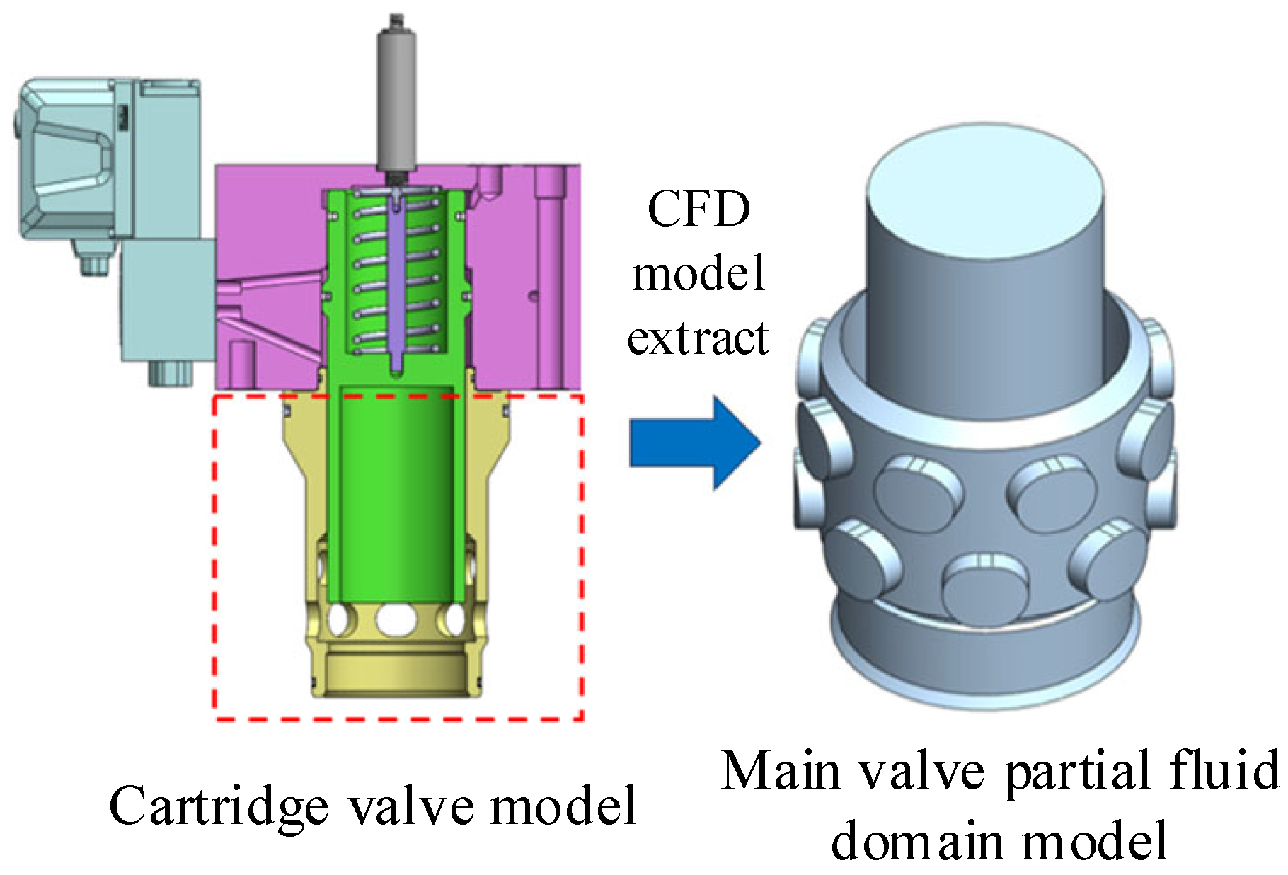
Based on the three-dimensional model and related conditions, a proportional throttle valve flow field model was established as shown in Figure 4. Fluid finite element software was employed to conduct a simulation analysis of the flow field around the proportional throttle valve, which involved the simulation and analysis of various spool throttle port structures. It was found that different valve port structures have different effects on the fluid motion within the valve body.

Figure 4.
Cartridge valve models and fluid domain models.
In this flow simulation analysis, the fluid was considered to be a single phase, thus belonging to the single-phase flow model. The Reynolds number was employed in the calculation of the fluid flow at the valve mouth, considering the occurrence of turbulence. Consequently, the flow simulation model utilized unsteady time-averaged continuity equations, and the standard k-ε turbulence model was employed to assess the impact of turbulence on the flow field. The key reasons for choosing the k-epsilon turbulence model were its ability to simulate high Reynolds number turbulence efficiently, its extensive validation in engineering practice, and its compatibility with the objective of this study (linear flow optimization).
According to the actual use of working conditions, the fluid medium selection of 68 # hydraulic oil, the boundary conditions are shown in Table 2.
Table 2.
Boundary conditions and parameter settings.
3.3. Flow Linearity Simulation of Four Different Structures
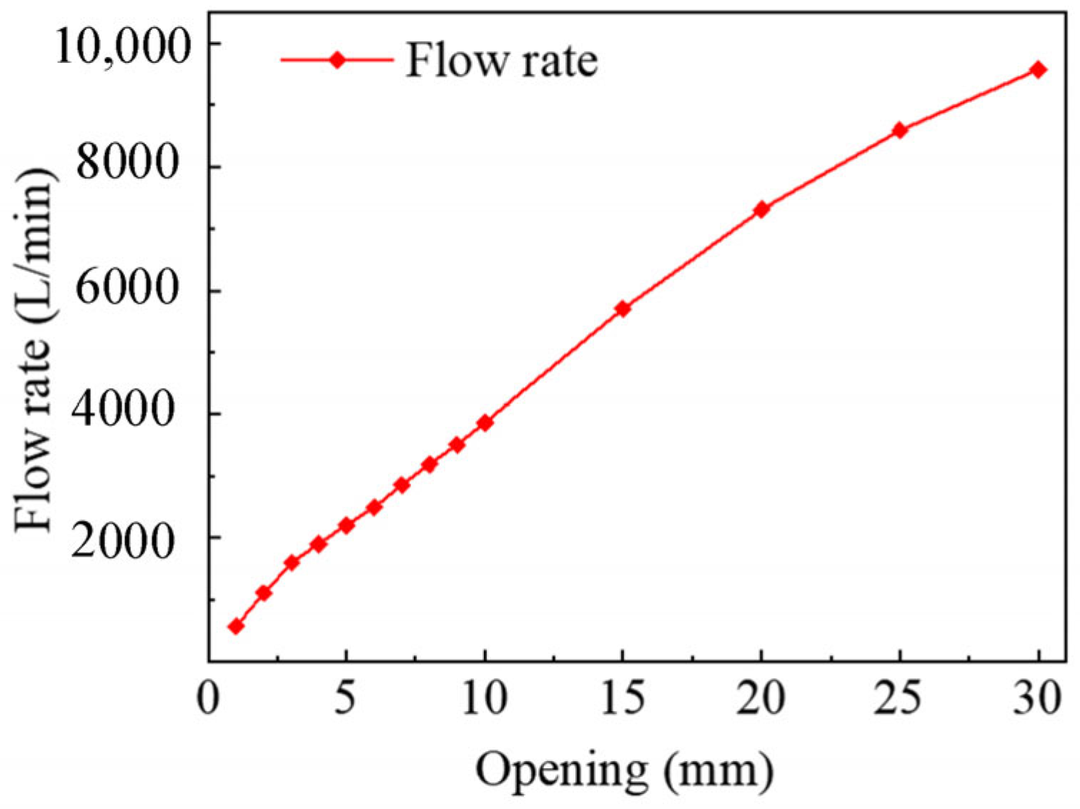
Firstly, the flow field simulation was conducted for a valve structure, in which the valve spool lacked a throttle port. The results are presented in Figure 5. From the curve, it can be concluded that the flow linearity was poor at the valve’s small opening positions, specifically within the range of 0–5 mm. This calls for structural optimization and should be addressed in future research.

Figure 5.
Flow rate versus opening degree curve.
In the context of structural simulation optimization for spool throttle port locations, this study initially investigated and analyzed four distinct spool throttle port structures: triangular, sector, rounded rectangle, and small rounded rectangle [19], as shown in Figure 6. The research aimed to determine the flow rate characteristics within a small opening degree range for each structure, identifying the relationship between the opening degree and flow rate changes. Based on this analysis, an optimal spool throttle port configuration was selected to explore specific dimensions that optimize the corresponding structure’s flow linearity.
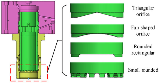
Figure 6.
Four kinds of orifice forms.
In this study, flow simulations are conducted for four different spool throttling port structures, calculating the corresponding simulation data and curves, as shown in Figure 7. The flow rate through the triangular throttle port increased gradually in the corresponding opening degree, with the growth rate transitioning from slow to fast. Under the corresponding opening degree, the flow rate through the fan-shaped throttle port increased faster than that through the triangular throttle port, but the flow linearity was poor, with a growth rate transiting from slow to fast. For the rounded rectangle and the small rounded rectangle throttle ports, which share a similar structural shape, a comparison was made between the two structures. The trend and law of flow rate changing with opening degree were found to be identical for both structures. For the rounded rectangular and small rounded rectangular throttle ports, since they share the same structural shape, the changing of their flow rate followed the same trend and law with the opening degree. However, the small rounded rectangular structure can be optimized in terms of size by adjusting the available space. Therefore, in order to obtain a better-sized throttle port structure that meets the requirements for flow linearity, this study subsequently concentrated on size optimization of small rounded rectangular throttle port structure.
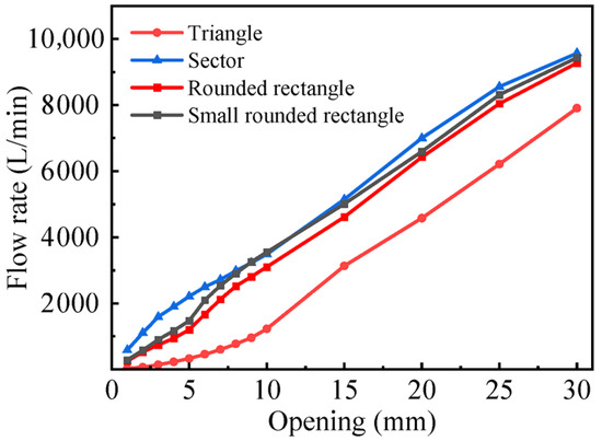
Figure 7.
The curve of the flow rate with an opening degree under four different orifice forms.
3.4. Optimization
3.4.1. Orthogonal Test Program Design
In the context of the four spool throttle port structures that exhibited small rounded rectangular forms under optimal linearity conditions, the subsequent focus was on simulation-based optimization analysis of these structures, aiming to find the spool throttle port structure size with good flow linearity.
Therefore, a detailed analysis of the structural position dimensions for the small rounded rectangle throttle port was conducted, as shown in Figure 8. Five critical dimensions were identified: the height of the small rounded rectangle h, length L, rounded corner α1, rounded corner α2, and inclination β. This paper mainly investigated the impact of these dimensions on flow linearity, particularly at small opening. Thus, a height of 5 mm for small rounded rectangle was selected for subsequent analysis. Based on this condition, the simulation-based analysis focused on the optimization of the remaining dimensions of the small rounded rectangle, with a particular emphasis on its size. Additionally, an orthogonal optimization method was employed to enhance the efficiency of the test.
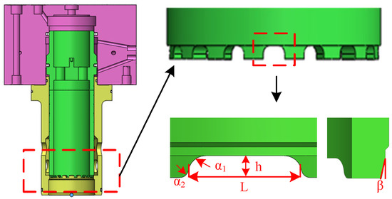
Figure 8.
Small rounded rectangular orifice structure size.
The orthogonal test process was designed as follows:
- (1)
- Determination of test factors, levels, and indicators.
Based on the flow field simulation analysis and throttle port structural characteristics, it was determined that the primary structural location of the spool throttle port was significantly affected by the flow. Therefore, L, α1, α2, and β were selected as the four influencing factors of this flow analysis orthogonal test, respectively, and are represented by the uppercase letters A, B, C, and D. Four levels were selected for each factor, and the specific levels for each factor are presented in Table 3.
Table 3.
Orthogonal test factor level table.
The structural dimensions of the spool throttle port were optimized to achieve a linear relationship between the flow rate and the valve opening degree. Consequently, the flow rate of the proportional throttle valve at different opening degrees was selected as the primary index to determine the optimal structural dimensions.
- (2)
- Orthogonal table composition.
Choosing an appropriate orthogonal table was a necessary step to ensure the smooth progression of orthogonal tests. This table was constructed using the Latin method and orthogonal Latin method, and its typical form is represented by (12):
where L represents the symbol for the orthogonal table; n represents the number of rows of orthogonal table; a represents the number of levels for each factor; and q represents the number of columns of orthogonal table.
For the current study, which involves four factors, it was necessary to select an orthogonal table from the Ln(4m) type. Given that m should be at least 4, the choice of L16(45) was appropriate for this experiment.
3.4.2. Orthogonal Test Results and Analysis
By calculating the polar deviation, the intuitive analysis method provided a comprehensive comparison of the influence of each factor and its level on the test indexes in orthogonal test, aiming to identify the optimal test scheme. Table 4 presents the results of the intuitive analysis for the proportional throttle valve spool throttle port structure flow orthogonal test, which lists 16 groups of tests conducted at proportional throttle valve under five different flow sizes. The E column represents the blank column, which plays a vital role in eliminating the interaction between random errors and test factors.
Table 4.
Analysis table of orthogonal test results under different opening degrees.
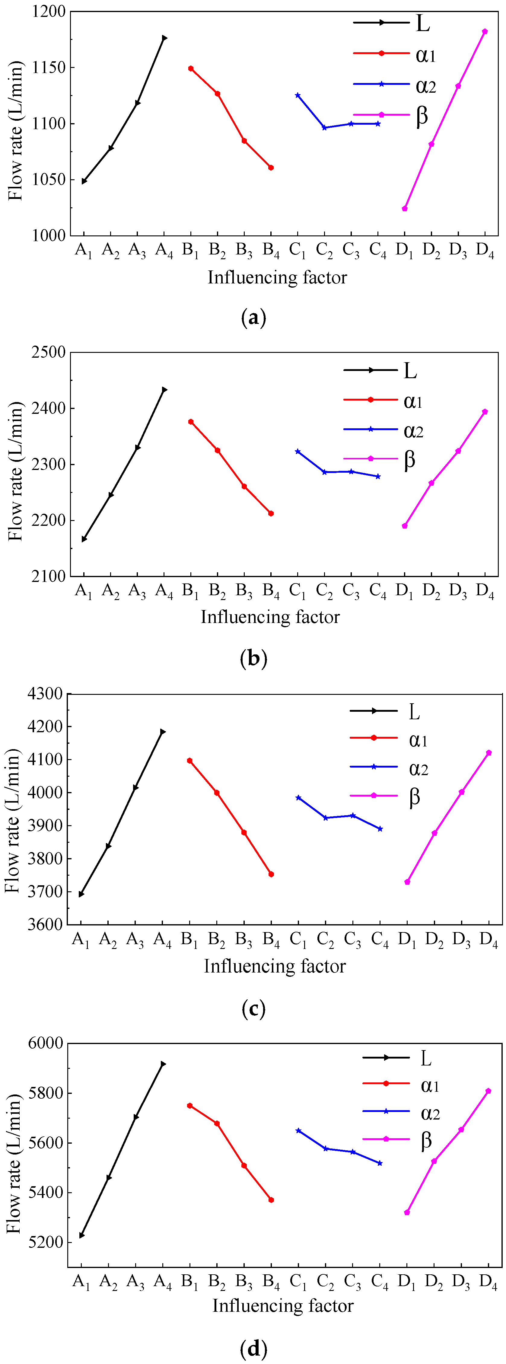
Figure 9 shows a schematic diagram of the influence of various factors on the flow rate of a proportional throttle valve under different opening degrees. The analysis shows that the flow rate of proportional throttle valve increases with the increase of L and β, and conversely, it decreases with the increase of α1 and generally decreases with the increase in α2.
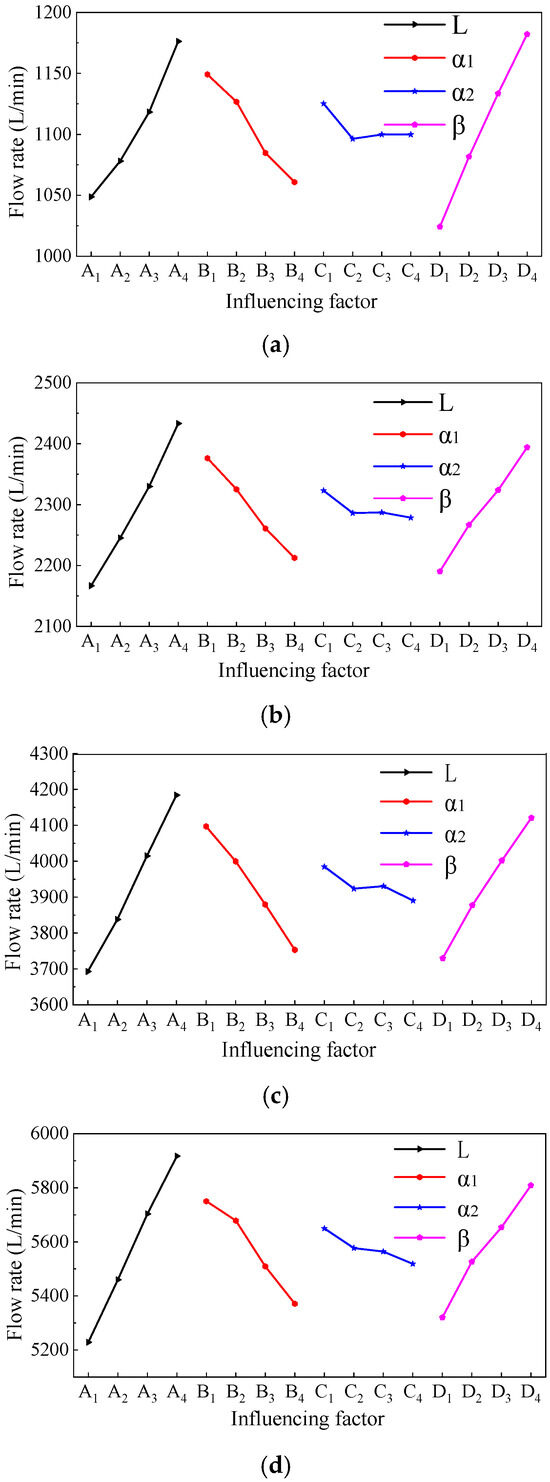
Figure 9.
A schematic diagram of the influence of various factors on the flow rate under different opening degrees: (a) 1 mm opening; (b) 2 mm opening; (c) 3 mm opening; and (d) 4 mm opening.
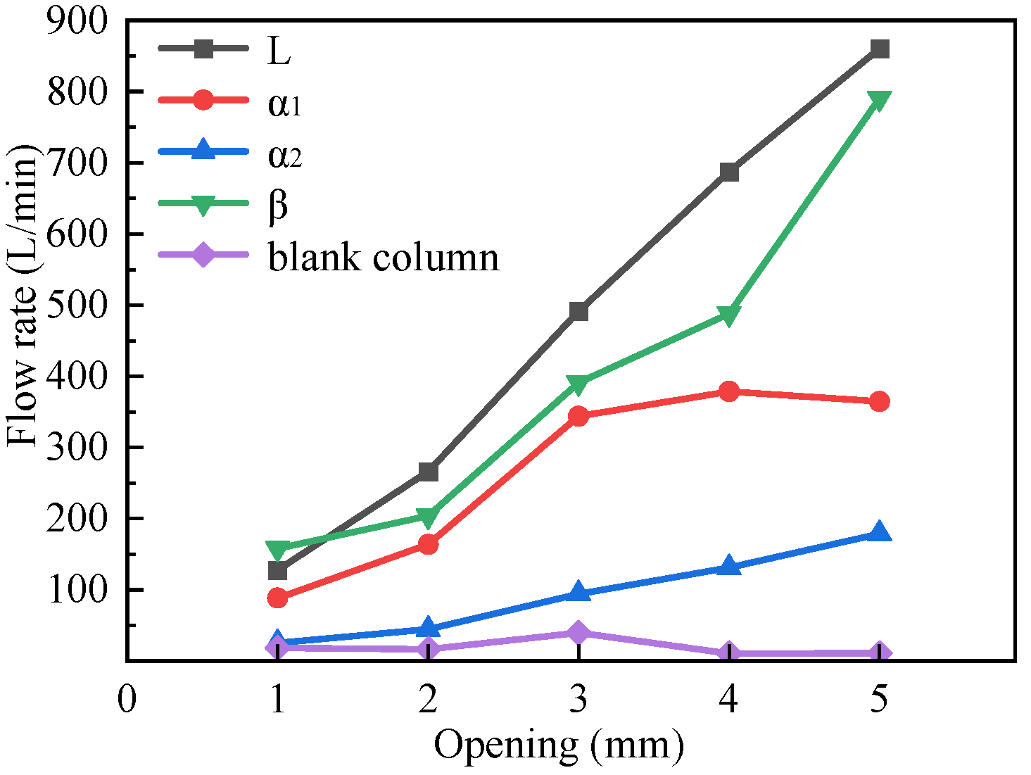
The analysis of each influence factor at different opening degrees, as shown in Figure 10, reveals the varying relationships between the factors and flow rate. Specifically, the analysis revealed that except for the 1 mm opening degree, the flow rate was greater under the influence of inclination angel than it was under the influence of other factors at different opening degrees such as the small rounded rectangle L, β, α1, and α2. The flow area at 1 mm opening degree was too small, and the impact of length on the flow area was not as significant as the impact of the inclination angel. This results in changes in the inclination angle in the area of flow, and the longer the length of the change was, the more pronounced the change in the inclination angle became. When each factor was analyzed individually, it was found that both length and inclination angel played the most significant effect on flow rate as the opening degree increases.
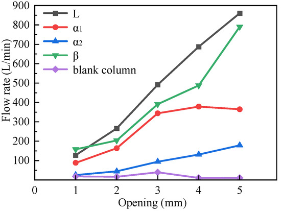
Figure 10.
The curve of each influencing factor with the opening degree.
This paper analyzed the optimal combination of structural forms in each opening degree by considering the effects of various factors on flow rate variation, achieving optimal flow linearity in different opening degrees. From the analysis of the flow data in Table 4, it can be seen that the flow rate was lower than the target flow rate for all combinations of influencing factors when the opening degree was 1 mm and 2 mm. Conversely, the flow rate was higher than the target flow rate for all combination of influencing factors when the opening degree was 4 mm and 5 mm, and only when the opening degree is 3 mm, the number of combinations of influencing factors that meet the target flow rate was higher. Therefore, these combinations of influencing factors that meet the target flow rate at 3 mm opening were selected, for they may exhibit the most proximity to the target flow rate in other opening degrees.
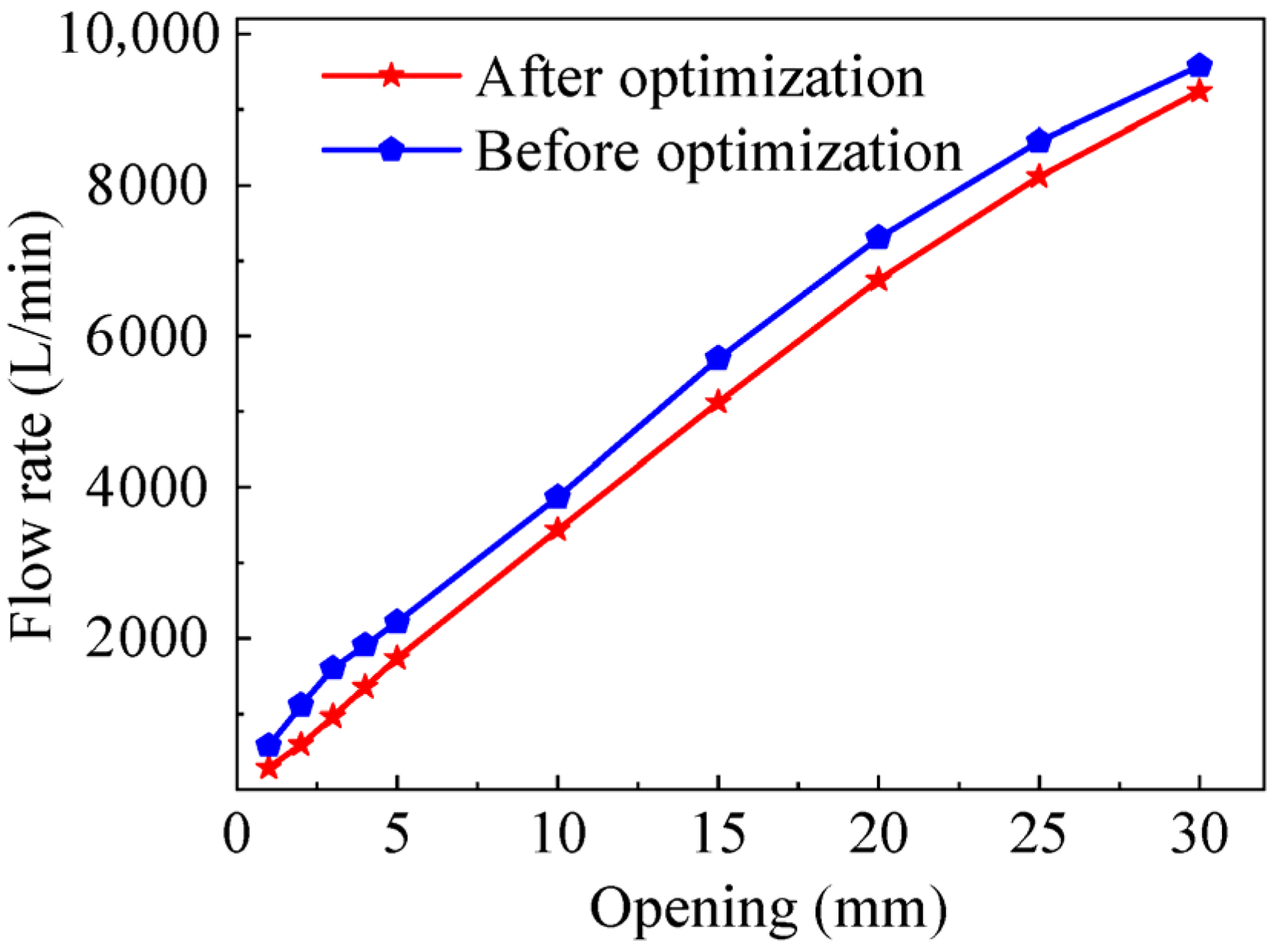
Finally, the optimal combination of structural forms was selected, including the small rounded rectangle with a length of 26 mm, the rounded corner 1 with a radius of 4 mm, the rounded corner 2 with a radius of 2 mm, and the inclination angle of 12°. When the flow linearity was at its best, the optimal selection of the four influencing factors A2B3C4D2 was obtained. The selected structure size was used for the full-opening degree simulation, and the flow behavior of the spool in the valve without a throttle port was compared as shown in Figure 11. The figure clearly illustrates that the flow linearity of the optimized structure was significantly improved compared to that before optimization, thereby demonstrating the effectiveness and feasibility of flow linearity structure optimization method.
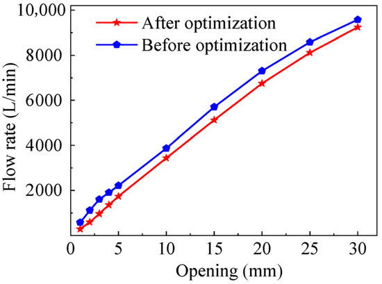
Figure 11.
The curve of the flow rate with the opening degree after optimization and before optimization.
In this paper, the CORREL function in Excel was used to judge the linearity. The CORREL function is the Pearson correlation coefficient, and the value range is [−1,1]. The closer the absolute value is to 1, the stronger the linear relationship between x and y is. Through calculation, the correlation coefficient before optimization is 0.996525323, and the correlation coefficient after optimization is 0.998088276. Under the opening degree of 0–5 mm, the correlation coefficient before optimization is 0.991325112, and the correlation coefficient after optimization is 0.999060787. It can be seen that the optimization effect is obvious.
4. Experimental Platform and Results
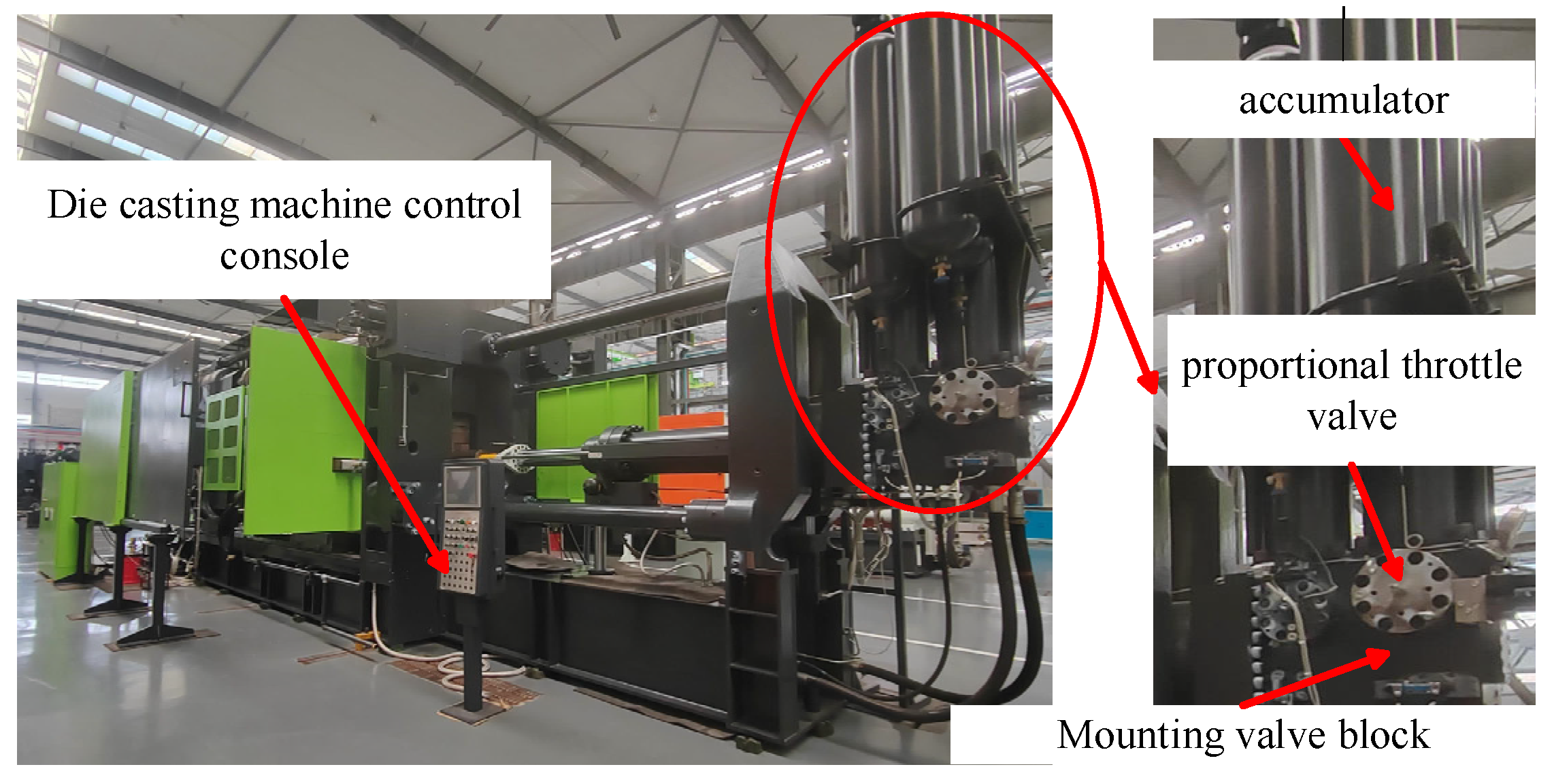
The main equipment required for the test is shown in Figure 12 and Figure 13. Figure 11 shows the test equipment for the die-casting machine. The main components used includes the accumulator on the die-casting machine, the developed proportional throttle valve, and the mounting block for installing the proportional throttle valve, which are mainly located in the rightmost area of the die-casting machine. Table 5 shows the parameters (type, accuracy) of the measuring and data acquisition equipment used for the test bench.
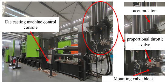
Figure 12.
Die-casting machine test equipment.

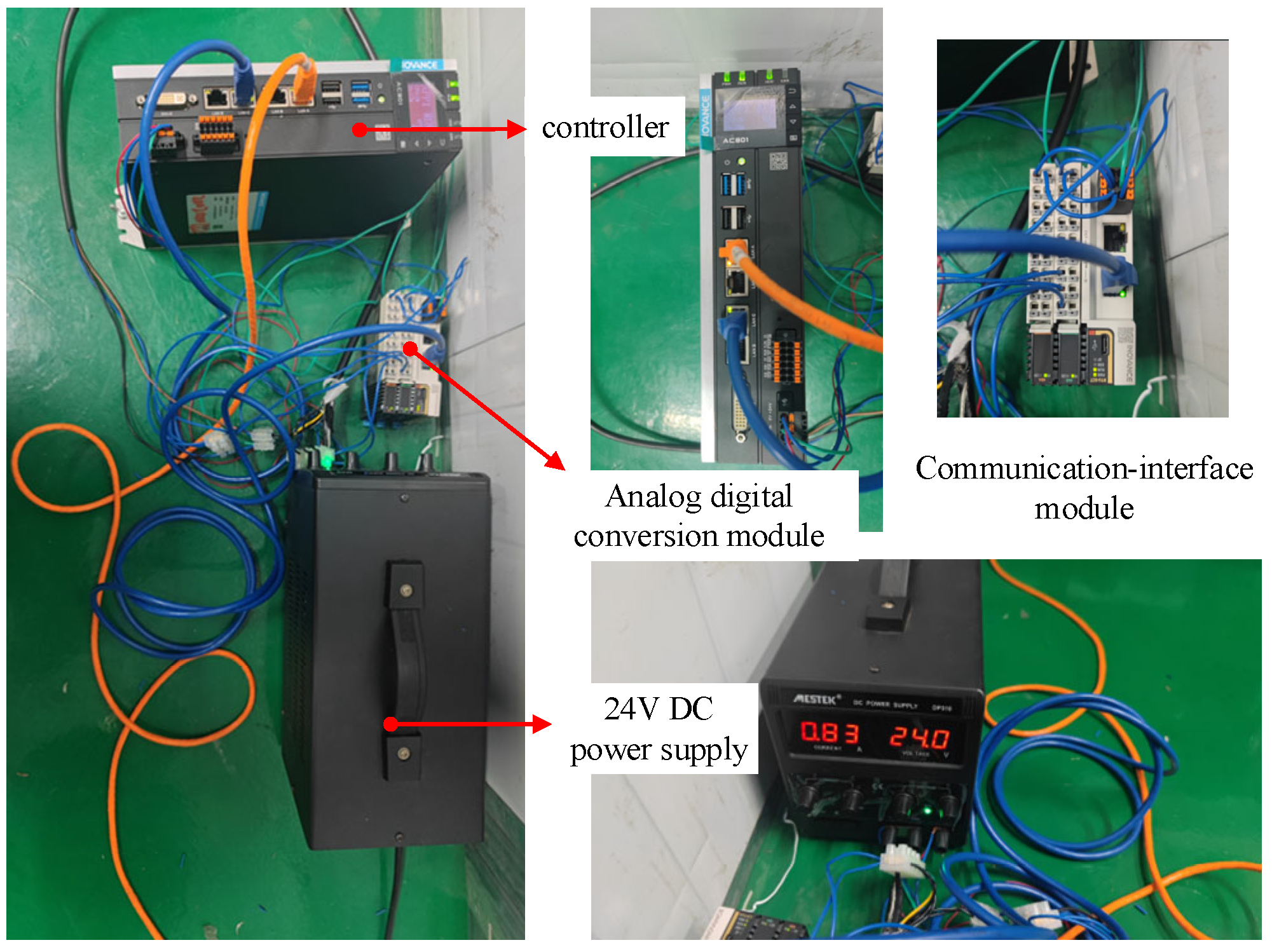
Figure 13.
Controller and conversion interface module.
Table 5.
Equipment used in the experiment.
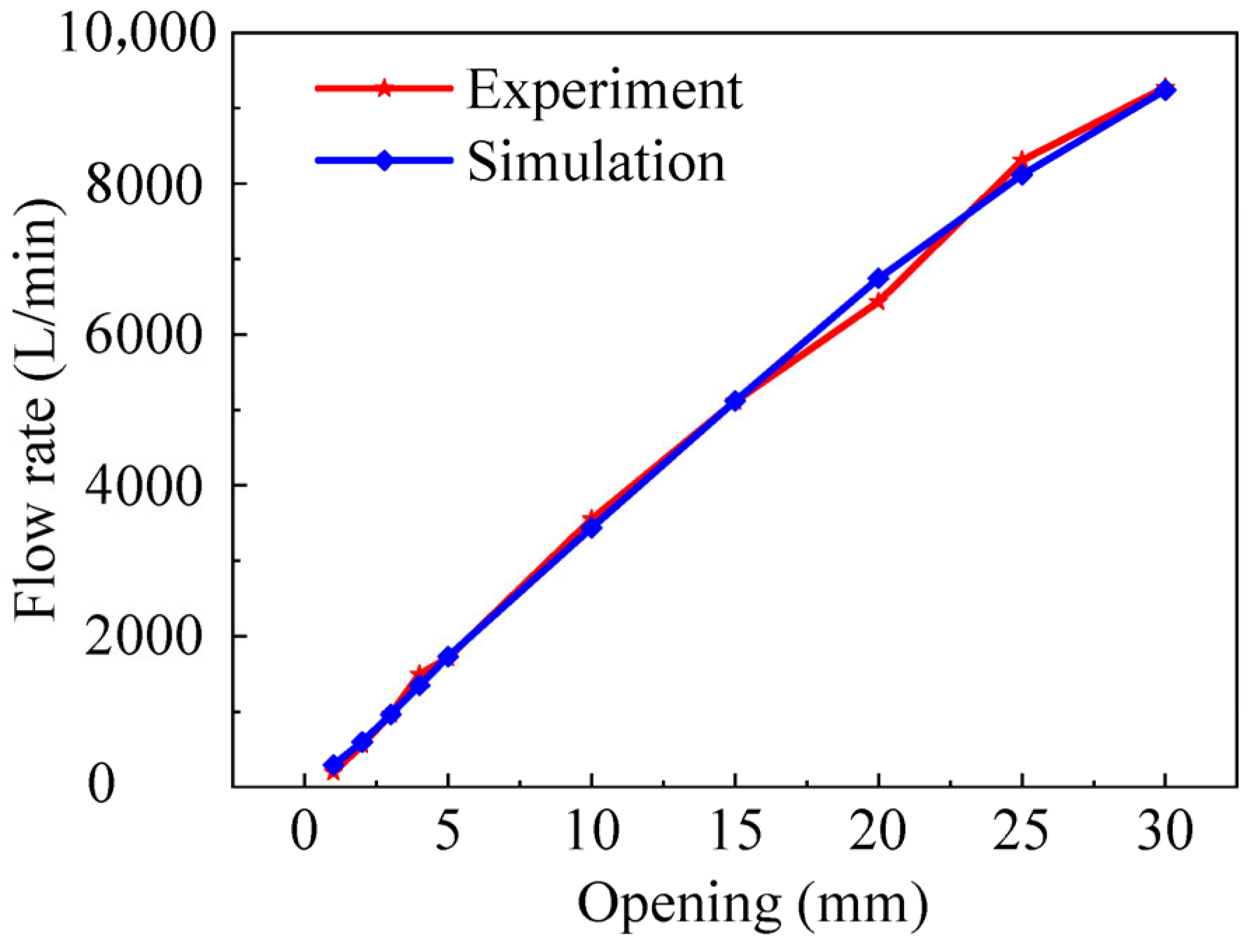
The processing of the test data involves several steps, including the calculation of pressure injection velocity and structure size of the through-flow and the determination of flow rate under a fixed differential pressure using accumulator pressure and pressure measured after the valve. Based on the calculated results, the curve of the flow rate in the opening degree is shown in Figure 14. As shown in the figure, the flow rate exhibits linear change within the opening degree of 0–15 mm, indicating good linearity for the developed proportional throttle valve in lower openings. This meets the target requirements and validates the feasibility of the flow linearity design method employed in the simulation part of this paper, which can be used to guide the structure design of proportional throttle valves. For opening degrees exceeding 15 mm, the flow rate increase gradually slows down so that with the increase in the opening degree, the pressure drop reduces slower. The analysis is conducted to obtain results, and it is primarily influenced by the proportional throttle valve rather than other structures. As the flow reaches a certain level, the flow rate also increases to a certain level. The analysis shows that it is primarily influenced by other structures rather than the proportional throttle valve, and after the flow rate increases again, it will lead to a significant increase in pressure drop. This will result in a higher flow rate as the degree of opening increases, but the rate at which the flow rate grows will slow down.
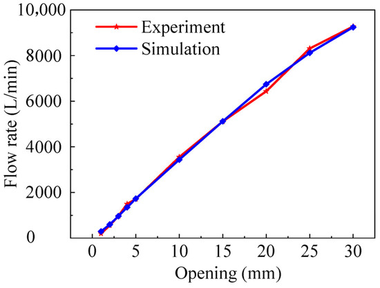
Figure 14.
The curve of flow rate with opening degree under pressure difference of 5 bar.
5. Conclusions
In this study, we investigate the flow field characteristics within a high-pressure, high-flow proportional throttle valve by means of simulation and experimental analysis. The purpose of this paper is to determine how the structural parameters of the high-pressure, high-flow proportional throttle valve affect the flow size and flow linearity. The main conclusions of this study are as follows:
- (1)
- The optimum flow linearity associated with the small rounded rectangle structure is obtained from the simulation analysis of four types of throttle orifices, namely triangle, sector, rounded rectangle, and small rounded rectangle.
- (2)
- By using orthogonal test and simulation analysis, it is found that the flow linearity of the proportional throttle valve with optimized structure is greatly improved by comparing it with the flow rate change curve of the spool in the form of no throttle port structure.
- (3)
- The simulation results and experimental test results show similar trends, verifying the accuracy of each other. Optimizing the parameters of the spool throttle port structure can effectively improve the flow linearity of the throttle valve.
This paper supplements the study of flow linearity under a small opening in the large-diameter proportional throttle valve. Through a targeted structural design, multi-parameter system optimization, and experimental verification, the control accuracy problem in practical engineering is solved to a certain extent, and it also provides a methodological reference for valve design under similar complex working conditions. The high-pressure large-flow proportional throttle valve studied in this paper is analyzed and studied from the valve sleeve opening and spool throttling without considering the influence of the spool valve sleeve fitting structure and the proportional throttle installation structure on the flow linearity of the proportional throttle valve. This aspect needs to be further studied and explored, and the research work on this part of the structure needs to be increased.
Author Contributions
Methodology, L.Y.; Software, B.W. and C.A.; Formal analysis, B.W.; Investigation, T.G., S.X. and C.A.; Data curation, T.G., Q.M. and S.X.; Writing—original draft, B.W.; Writing—review & editing, B.W., L.Y., T.G., Q.M., S.X. and C.A.; Visualization, L.Y.; Funding acquisition, L.Y. All authors have read and agreed to the published version of the manuscript.
Funding
Supported in part by the National Natural Science Foundation of China (No. 52305073) and S & T Program of Hebei ( No. 24461901D ).
Data Availability Statement
Data are contained within the article.
Conflicts of Interest
Author Shouwen Xiao was employed by the company Zhengzhou Aircraft Equipment Co., Ltd. The remaining authors declare that the research was conducted in the absence of any commercial or financial relationships that could be construed as a potential conflict of interest.
References
- Tamburrano, P.; Plummer, A.R.; Distaso, E.; Amirante, R. A review of direct drive proportional electrohydraulic spool valves: Industrial state-of-the-art and research advancements. J. Dyn. Syst. Meas. Control 2019, 141, 020801. [Google Scholar] [CrossRef]
- Plummer, A. Electrohydraulic servovalves-past, present, and future. In Proceedings of the 10th International Fluid Power Conference, Dresden, Germany, 8–10 March 2016. [Google Scholar]
- Sciatti, F.; Tamburrano, P.; Distaso, E.; Amirante, R. Digital hydraulic valves: Advancements in research. Heliyon 2024, 10, e27264. [Google Scholar] [CrossRef] [PubMed]
- Li, Y.; Li, R.; Yang, J.; Xu, J.; Yu, X. Recent advances in control strategies and algorithms for pilot-operated electro-hydraulic proportional directional valves. Proc. Inst. Mech. Eng. Part E J. Process Mech. Eng. 2024, 09544089231223065. [Google Scholar] [CrossRef]
- Xie, S.; Song, Z.; Huang, J.; Zhao, J.; Ruan, J. Characterization of two-dimensional cartridge type bidirectional proportional throttle valve. Flow Meas. Instrum. 2023, 93, 102434. [Google Scholar] [CrossRef]
- Zhang, X.; Wang, A.; Tang, J. Optimal design of multi-section proportional directional valve throttle grooves with artificial neural networks. MATEC Web Conf. EDP Sci. 2018, 237, 03003. [Google Scholar] [CrossRef]
- Ma, J.H. The Modeling and the Character Emulation of New Type Throttling Grooves on the Electromagnetic Proportion Throttle Valve. In Proceedings of the 2009 Second International Conference on Information and Computing Science, Manchester, UK, 21–22 May 2009; Volume 4, pp. 153–155. [Google Scholar]
- Wang, X.; Chang, J.; Wen, Y.; Zheng, J.; Sun, S. Analysis and emulation of steady-state characteristic for water hydraulic proportional throttle valve. In Proceedings of the 2009 IEEE 10th International Conference on Computer-Aided Industrial Design & Conceptual Design, Wenzhou, China, 26–29 November 2009. [Google Scholar]
- Liu, W.; Wei, H.J.; Hu, B. Analysis and Optimization of a Hydraulic-feedback Proportional Throttlecartridge Valve. Appl. Mech. Mater. 2014, 481, 162–170. [Google Scholar] [CrossRef]
- Xu, E.; Nie, C.; Jiang, X.; Miao, Z. Theoretical investigation on the throttle pressure reducing valve through CFD simulation and validating experiments. Korean J. Chem. Eng. 2021, 38, 400–405. [Google Scholar] [CrossRef]
- Zhang, Z.; Liang, L.; Wang, X.; Wang, D. Design for Improving the Linearised Flow Control Performance of Large Flow and High-pressure Proportional Valve. In Proceedings of the 20th International Conference of Fluid Power and Mechatronic Control Engineering, Jiaxing, China, 8–10 November 2019. [Google Scholar]
- Zhang, H.; Liao, Y.; Tao, Z.; Lian, Z.; Zhao, R. Modeling and Dynamic Characteristics of a Novel High-Pressure and Large-Flow Water Hydraulic Proportional Valve. Machines 2022, 10, 37. [Google Scholar] [CrossRef]
- Yao, J.; Yin, Y.; Dong, Z.; He, Y. Design of a 70 MPa Two-Way Proportional Cartridge Valve for Large-Size Hydraulic Forging Press. J. Beijing Inst. Technol. 2020, 29, 55–61. [Google Scholar]
- Liu, W.; Tian, J.; Wang, H.; Li, J.; Zhou, R.; Cao, Y. Investigation on the Dynamic Characteristics of a New High-Pressure Water Hydraulic Flow Control Valve. Machines 2024, 12, 640. [Google Scholar] [CrossRef]
- Gao, Q.; Zhu, Y.; Wu, C.; Jiang, Y. Development of a novel two-stage proportional valve with a pilot digital flow distribution. Front. Mech. Eng. 2021, 16, 420–434. [Google Scholar] [CrossRef]
- Han, M.; Liu, Y.; Wu, D.; Tan, H.; Li, C. Numerical Analysis and Optimisation of the Flow Forces in a Water Hydraulic Proportional Cartridge Valve for Injection System. IEEE Access 2018, 6, 10392–10401. [Google Scholar] [CrossRef]
- Avram, M.; Duminică, D.; Bucşan, C. Influence of the flow section geometry on the static characteristic curves of proportional hydraulic throttle valves. Appl. Mech. Mater. 2014, 555, 385–394. [Google Scholar] [CrossRef]
- Tan, L.; Xie, H.; Chen, H.; Yang, H. Structure optimization of conical spool and flow force compensation in a diverged flow cartridge proportional valve. Flow Meas. Instrum. 2019, 66, 170–181. [Google Scholar] [CrossRef]
- Meng, B.; Hao, X.; Jian, R.; Sheng, L. Theoretical and experimental investigation on novel 2d maglev servo proportional valve. J. Chin. Aviat. Engl. 2021, 34, 416–431. [Google Scholar] [CrossRef]
- Zhang, X.; Wang, A.; Chen, Y.; Jiang, T. Optimization on the Topological Coupling-Throttling Structures for Directional Valves. IOP Conf. Ser. Earth Environ. Sci. 2020, 585, 012171. [Google Scholar]
- Xie, H.; Tan, L.; Liu, J.; Chen, H.; Yang, H. Numerical and experimental investigation on opening direction steady axial flow force compensation of converged flow cartridge proportional valve. Flow Meas. Instrum. 2018, 62, 123–134. [Google Scholar] [CrossRef]


Disclaimer/Publisher’s Note: The statements, opinions and data contained in all publications are solely those of the individual author(s) and contributor(s) and not of MDPI and/or the editor(s). MDPI and/or the editor(s) disclaim responsibility for any injury to people or property resulting from any ideas, methods, instructions or products referred to in the content. |
© 2025 by the authors. Licensee MDPI, Basel, Switzerland. This article is an open access article distributed under the terms and conditions of the Creative Commons Attribution (CC BY) license (https://creativecommons.org/licenses/by/4.0/).