
A Novel Design for Adjustable Stiffness Artificial Tendon for the Ankle Joint of a Bipedal Robot: Modeling & Simulation


Abstract
:1. Introduction

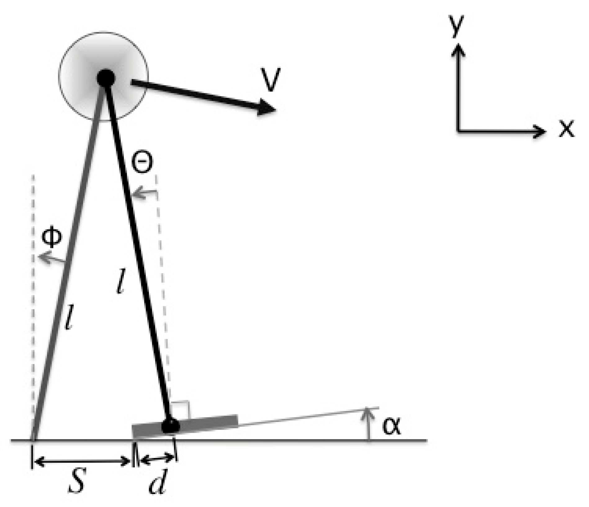
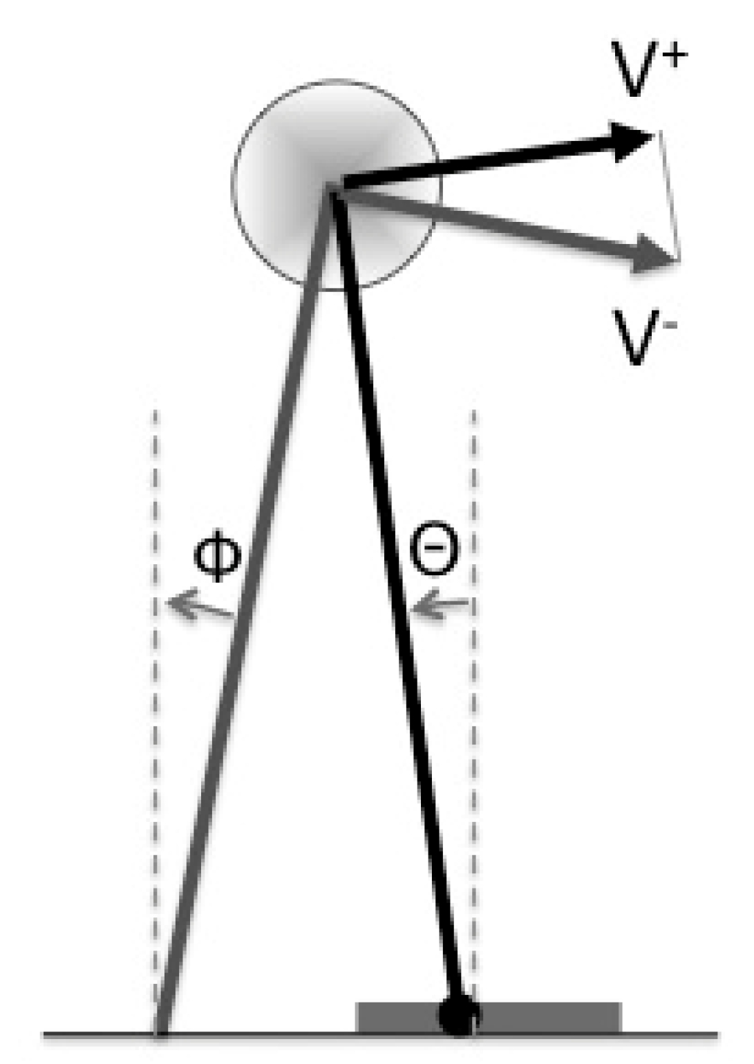
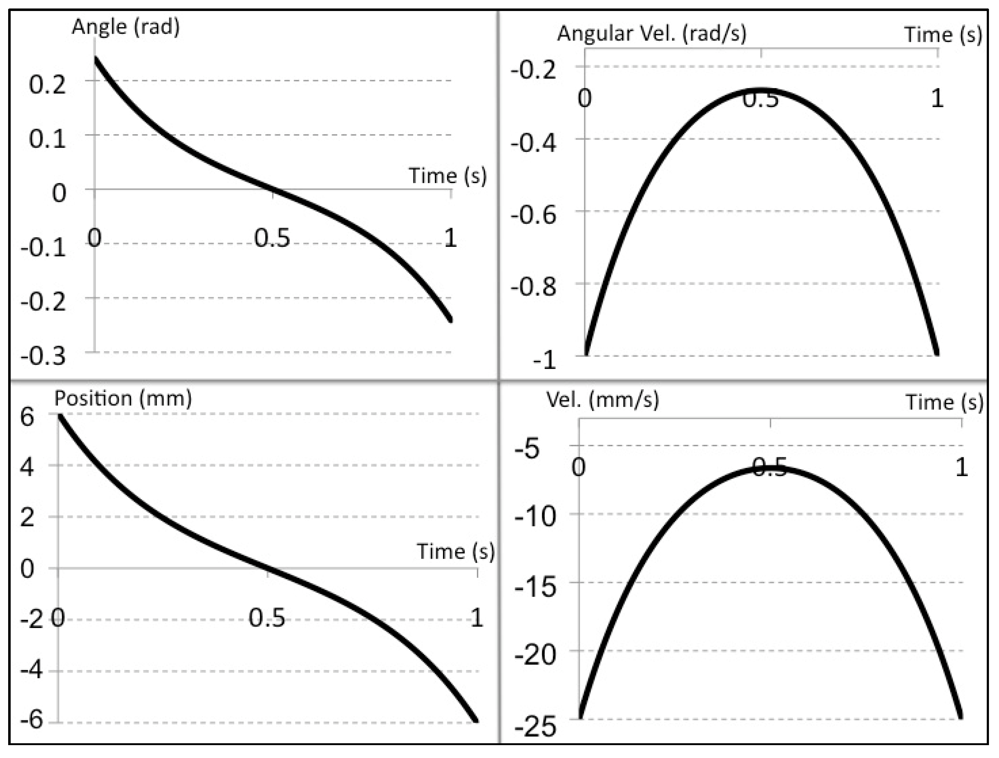
2. Analysis of the Ankle Joint’s Motion Performance


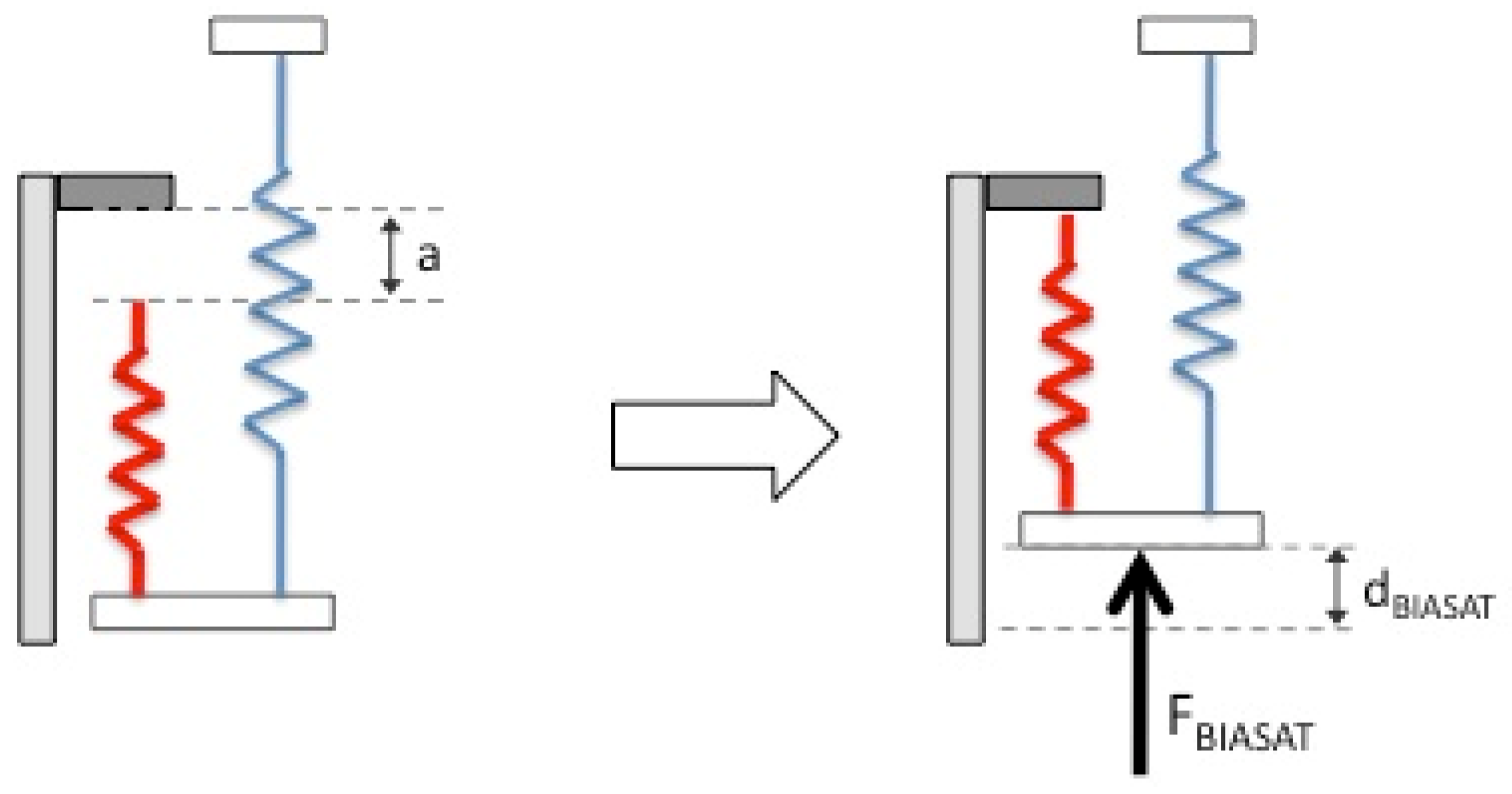
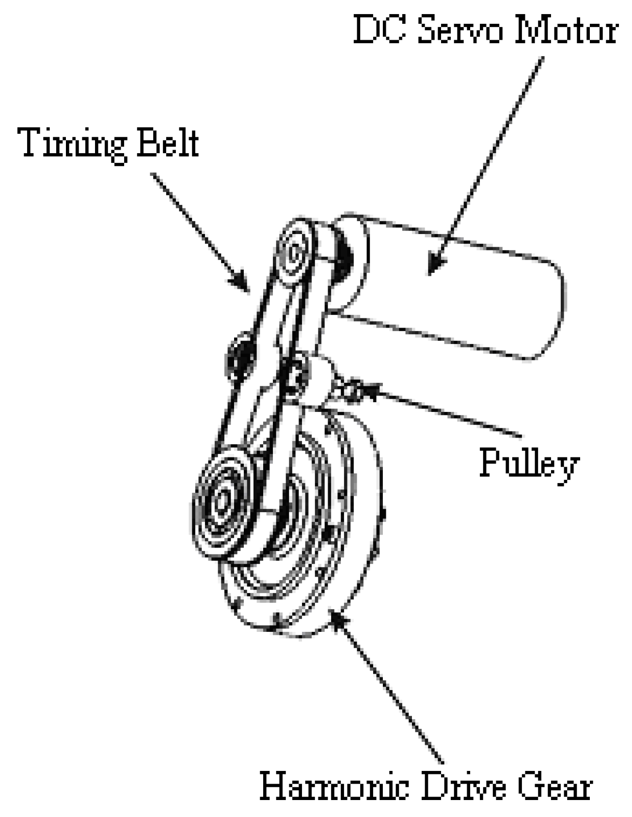
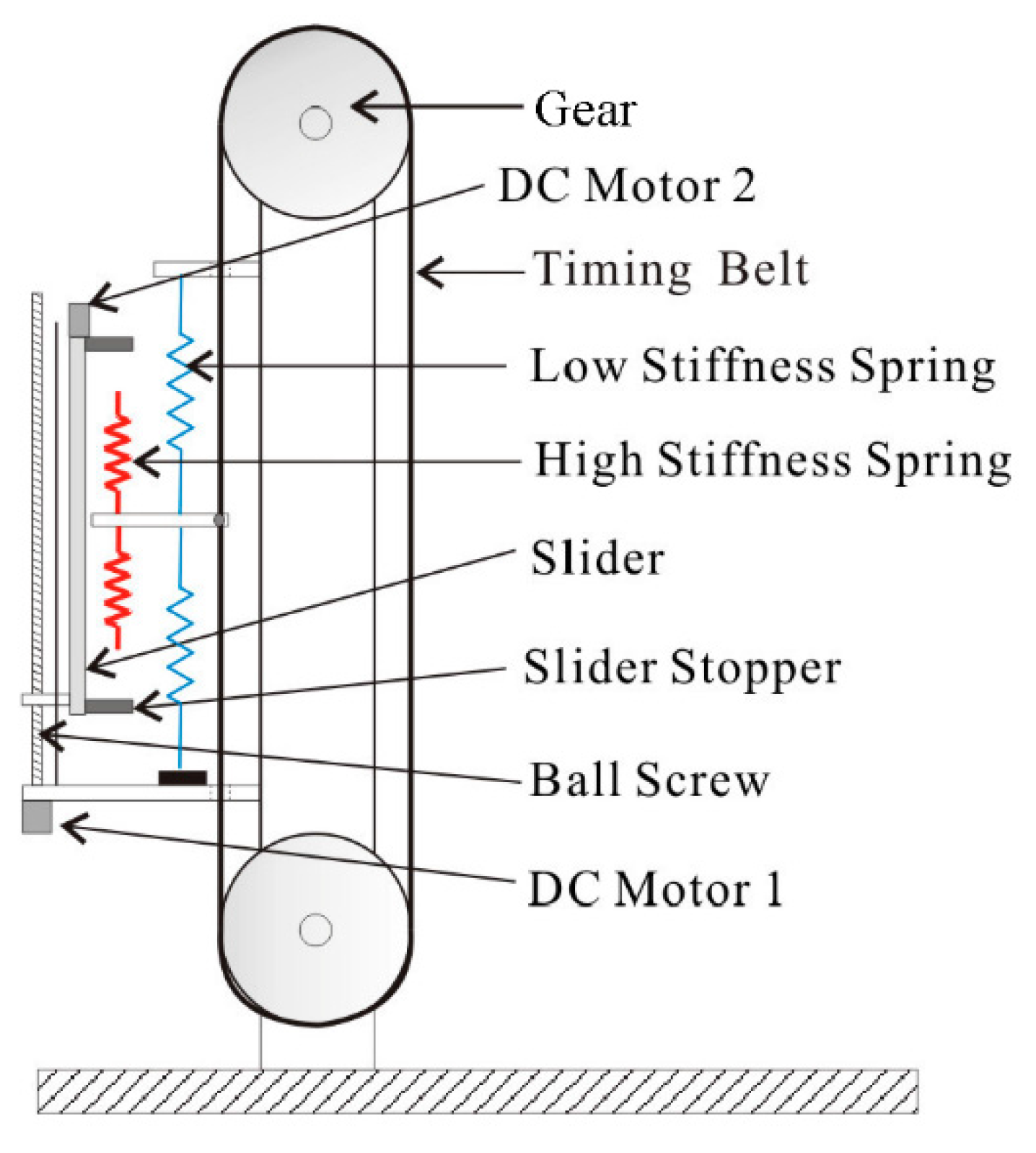
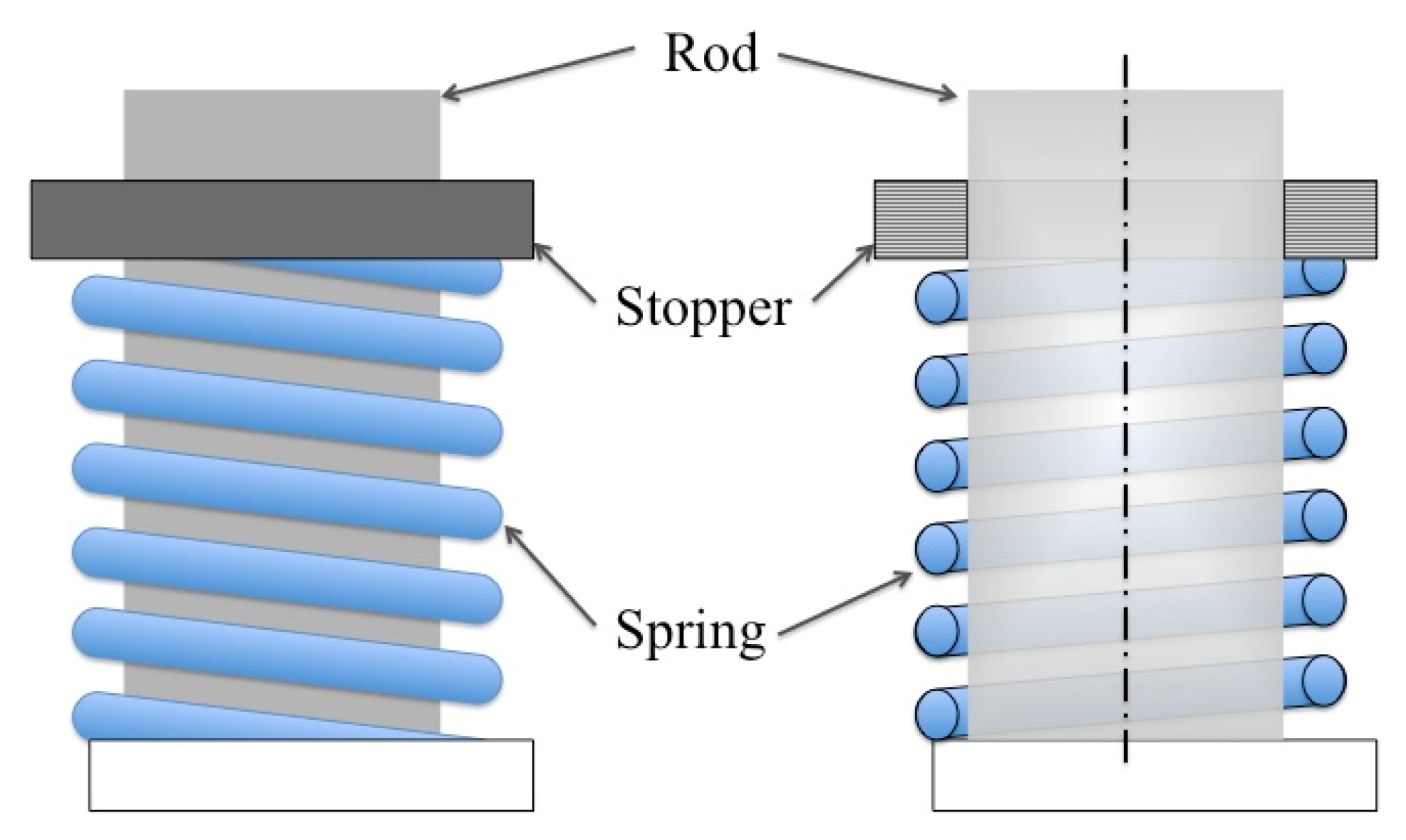
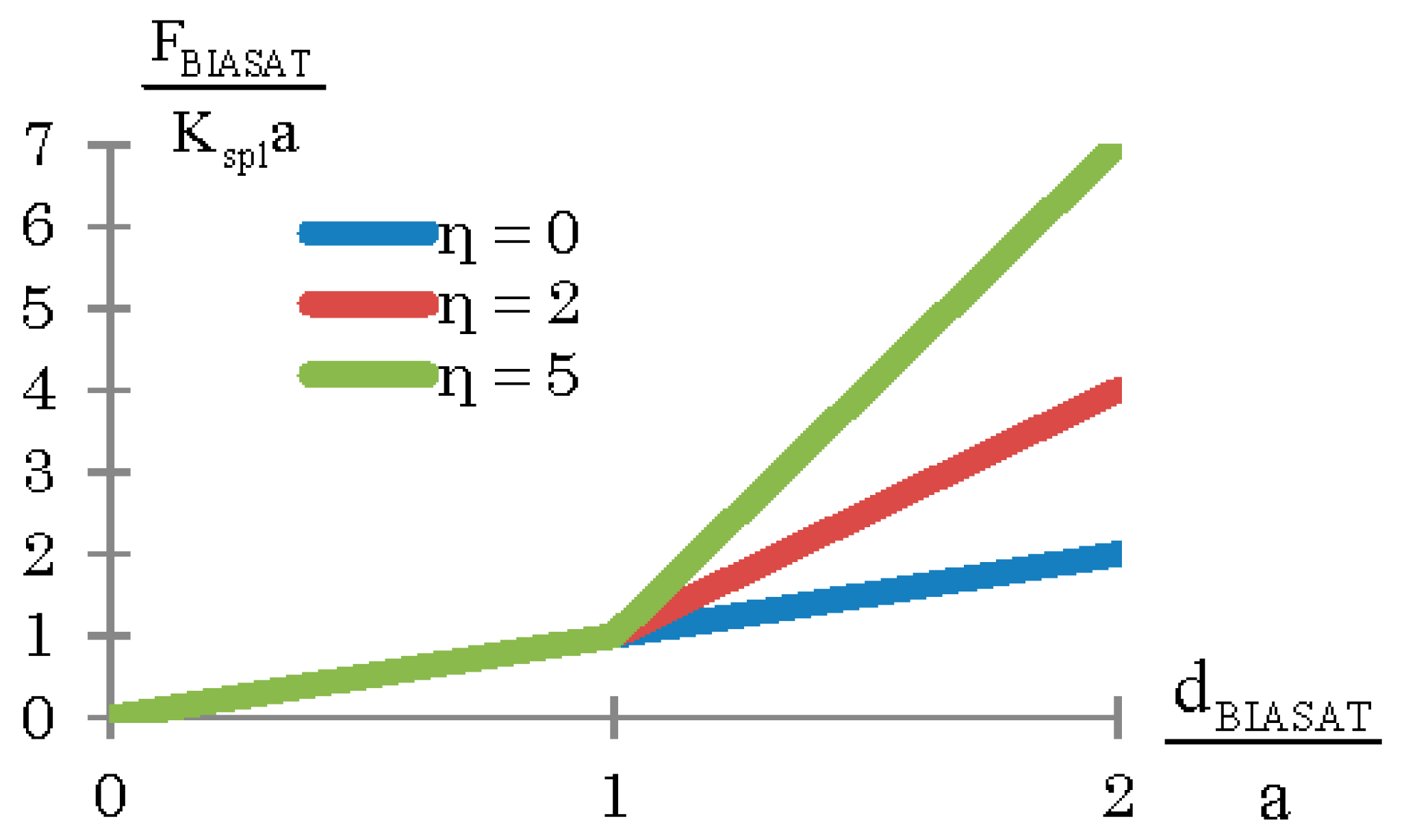
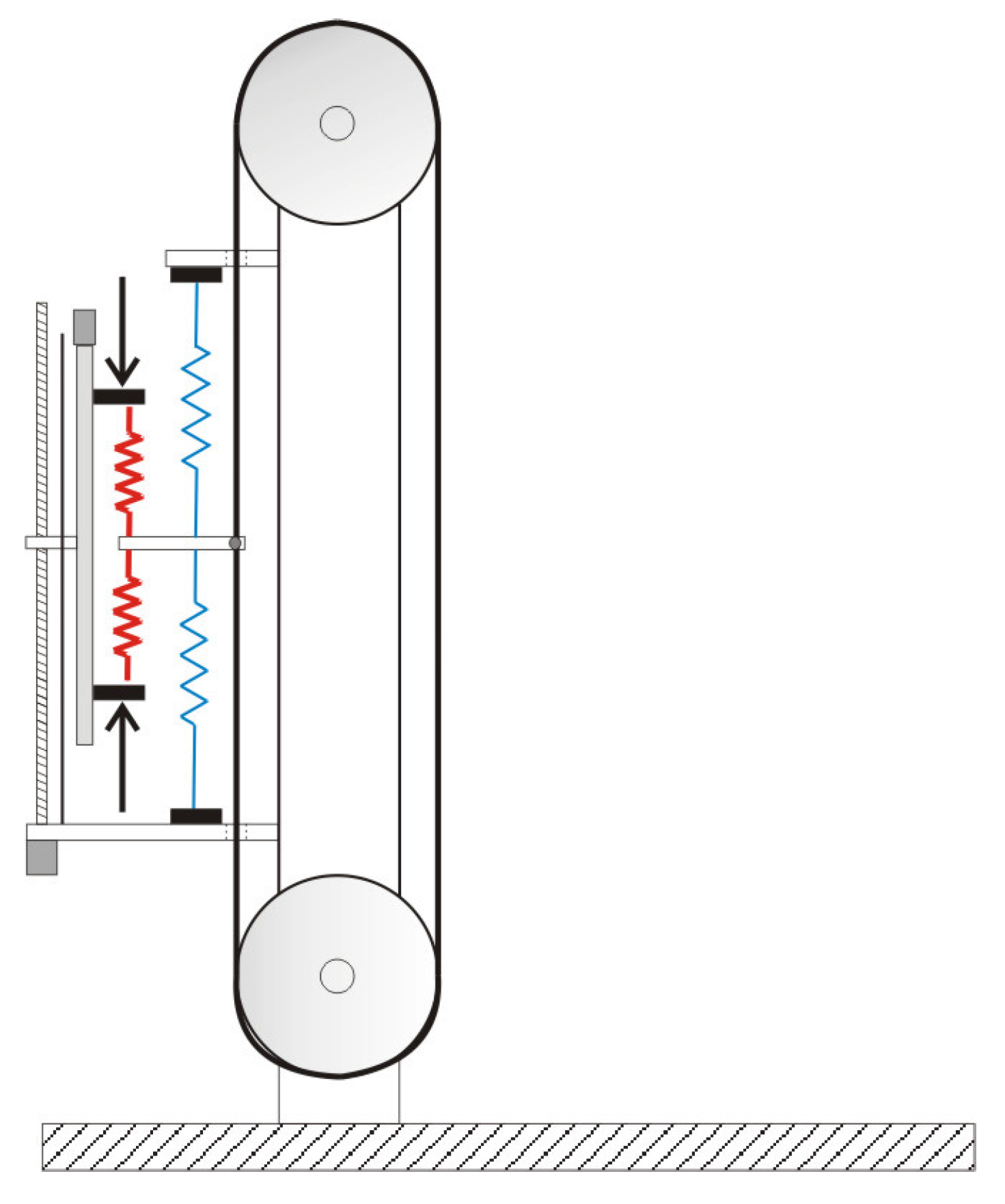
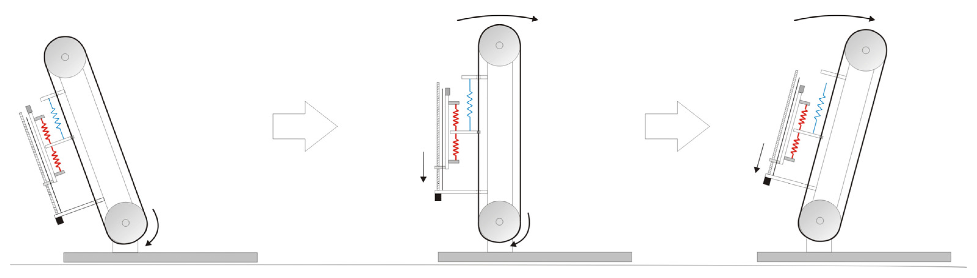
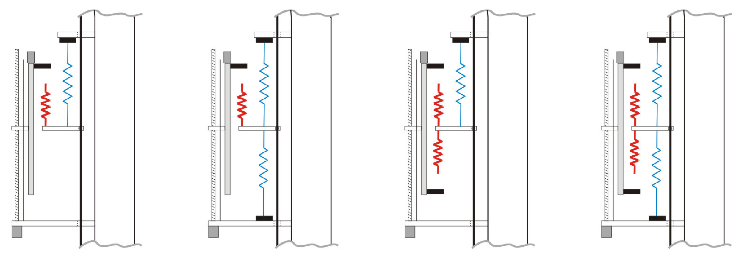
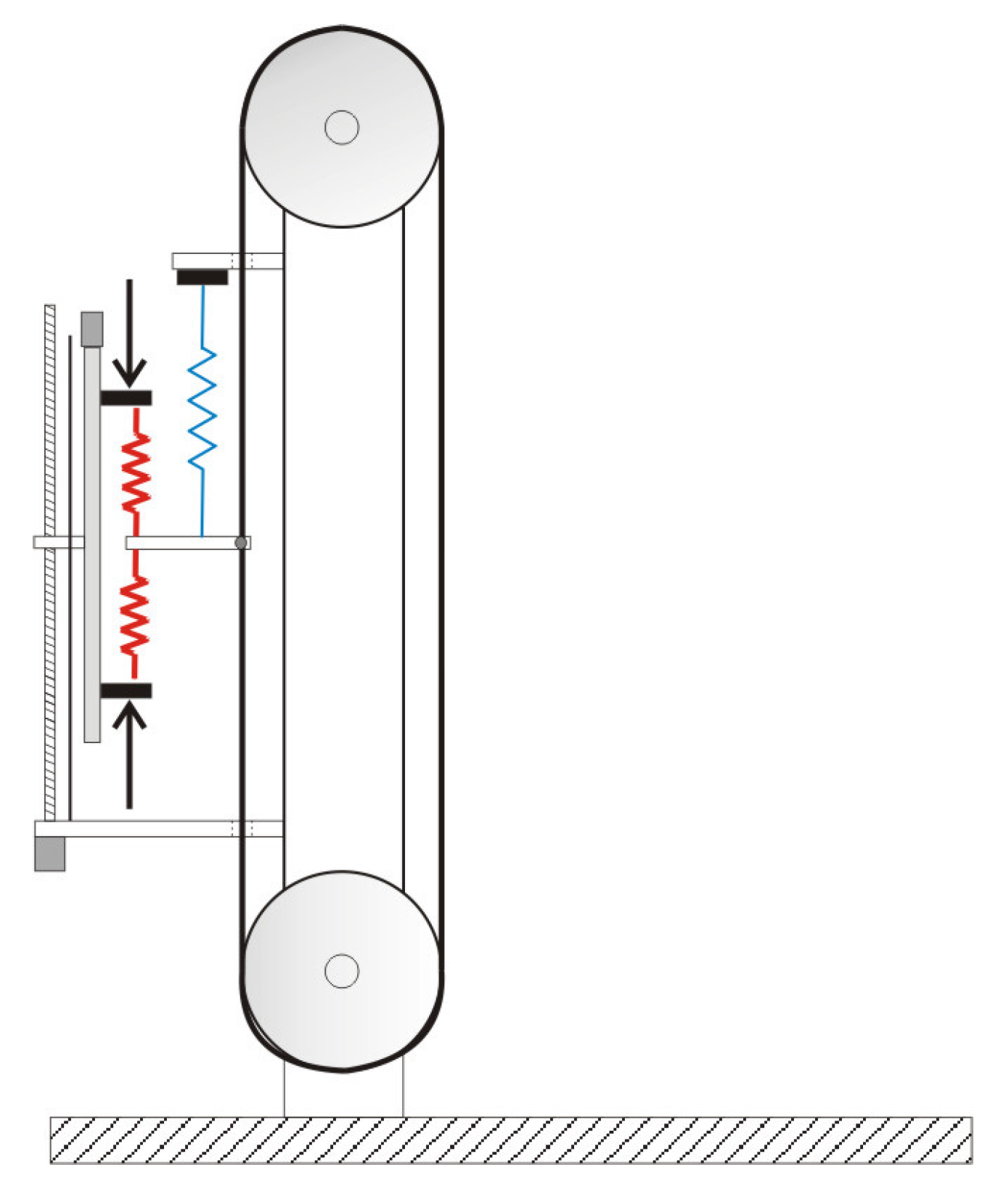
3. Design of the Bi-Directional Adjustable Stiffness Artificial Tendon


4. BIASAT Mechanism Control

4.1. Passive Mode Control

4.2. Active Mode Control

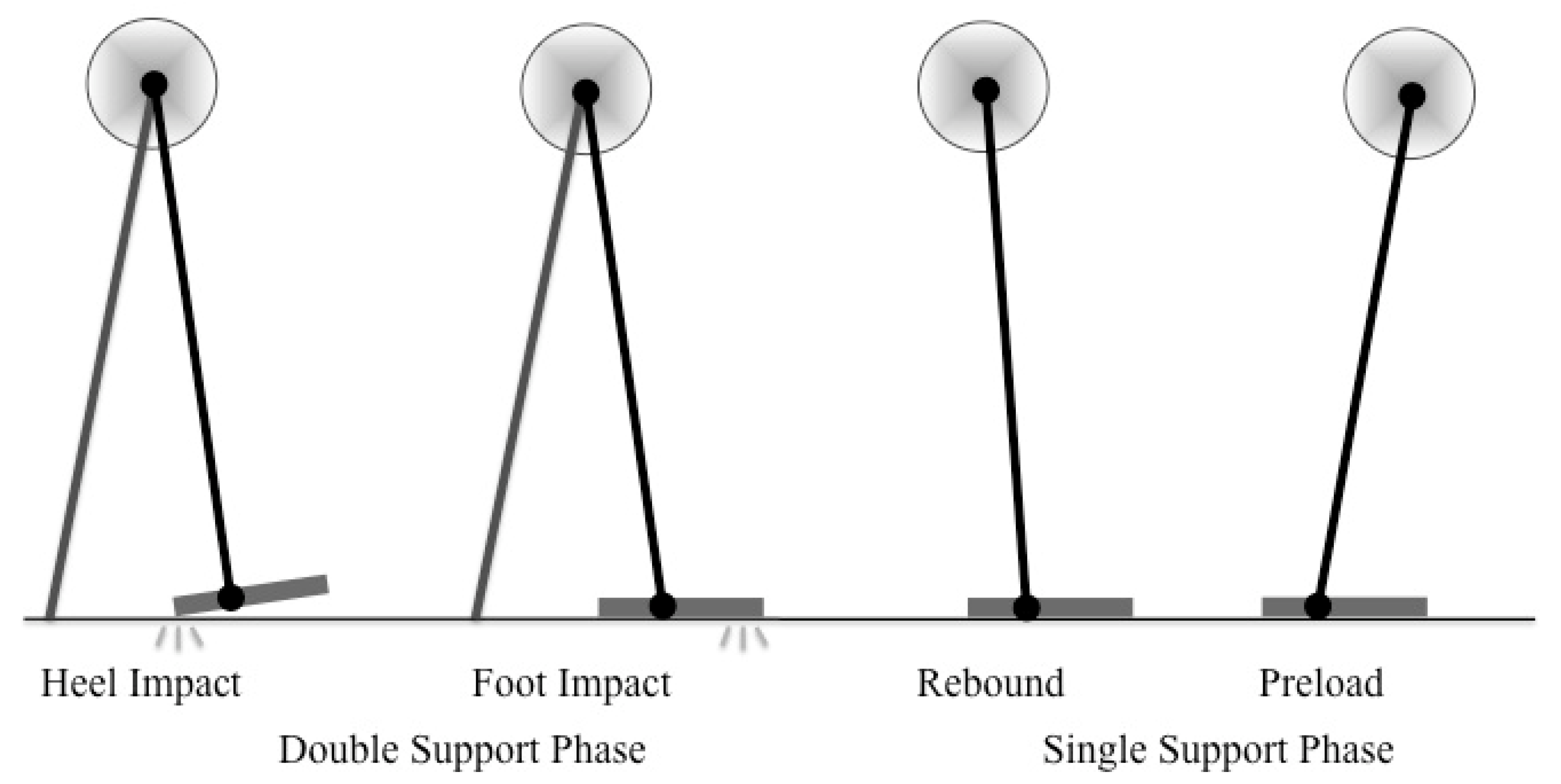
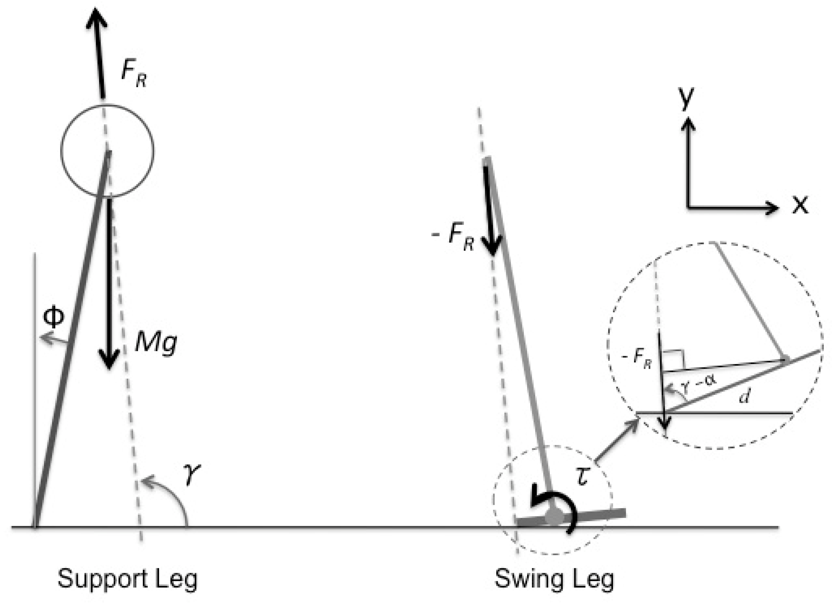
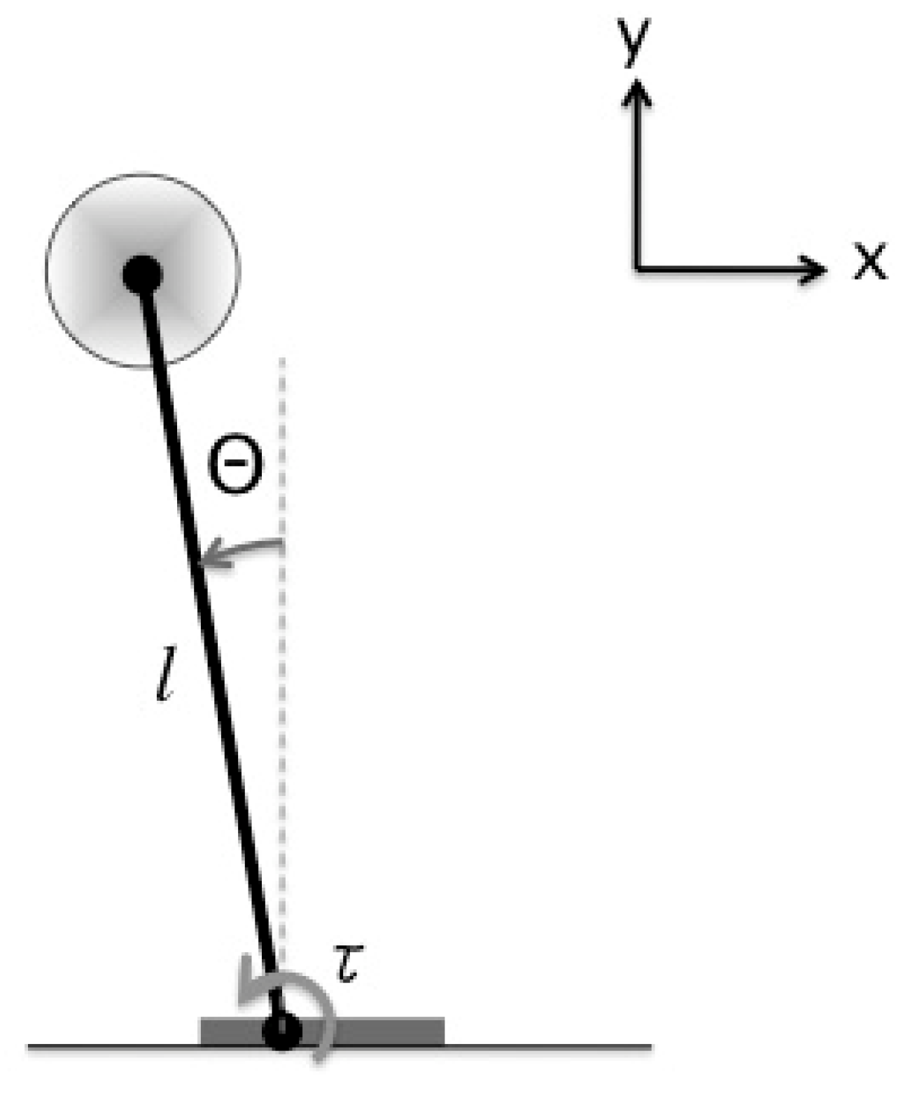
5. Dynamic Model of Bipedal Walking Robot

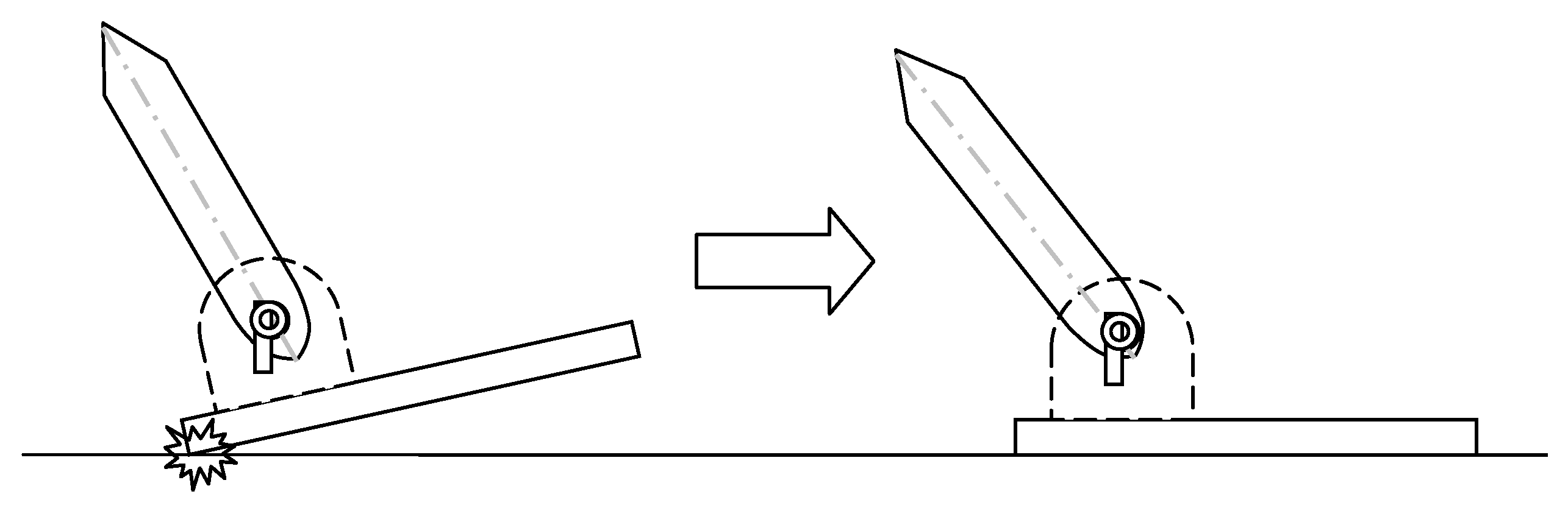
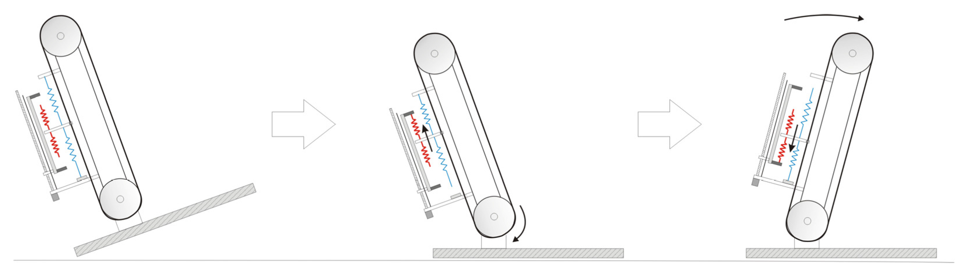
5.1. Heel Impact


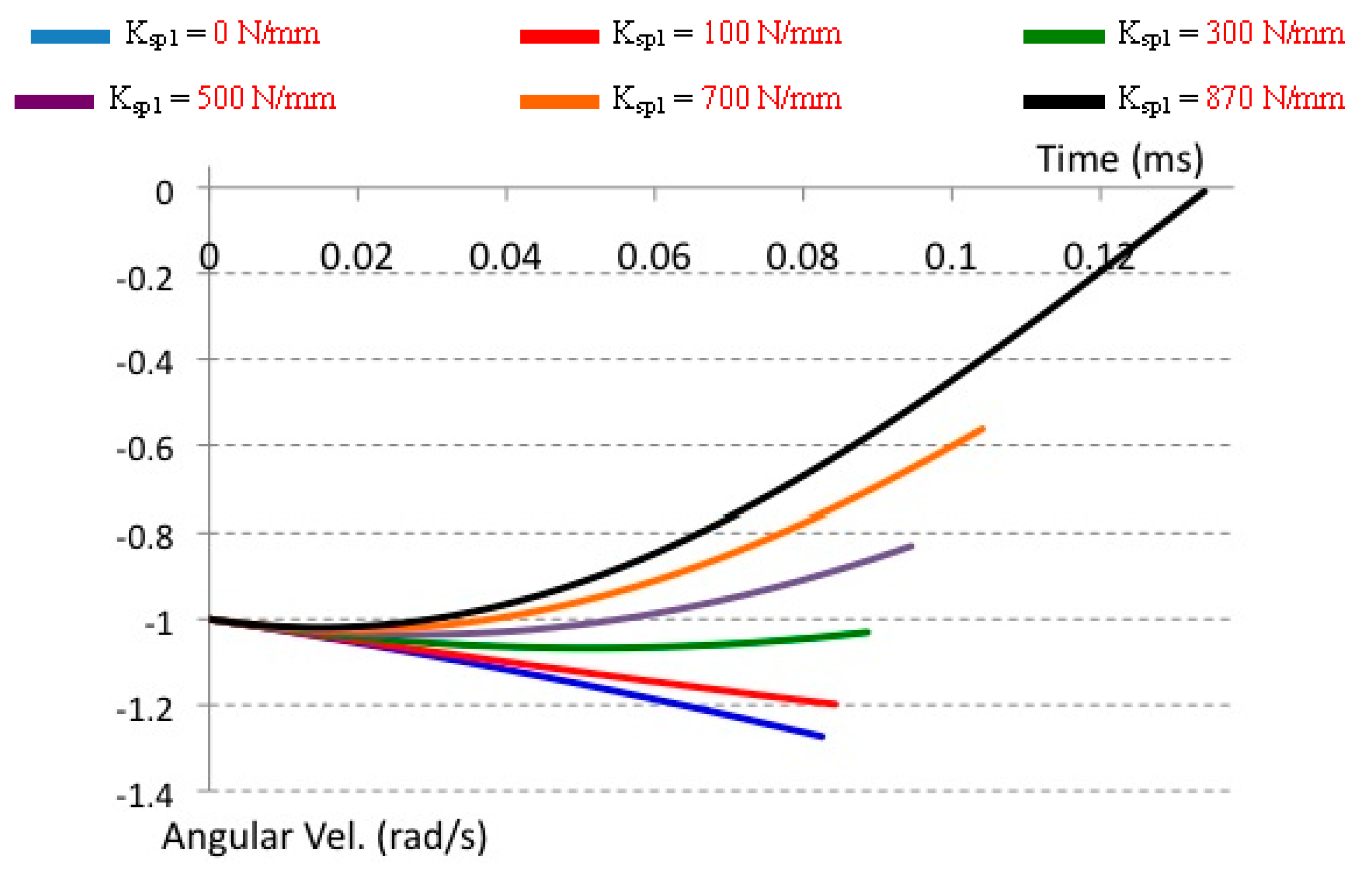
| Spring Stiffness (N/mm) | 0 | 100 | 300 | 500 | 700 | 870 |
|---|---|---|---|---|---|---|
| Calculated Angular Velocity (rad/s) | −1.2735352 | −1.198811298 | −1.033277201 | −0.83556868 | −0.573313407 | −0.120931885 |
| Measured Angular Velocity (rad/s) | −1.273648705 | −1.198207411 | −1.030770962 | −0.830323912 | −0.56210003 | −0.009155171 |

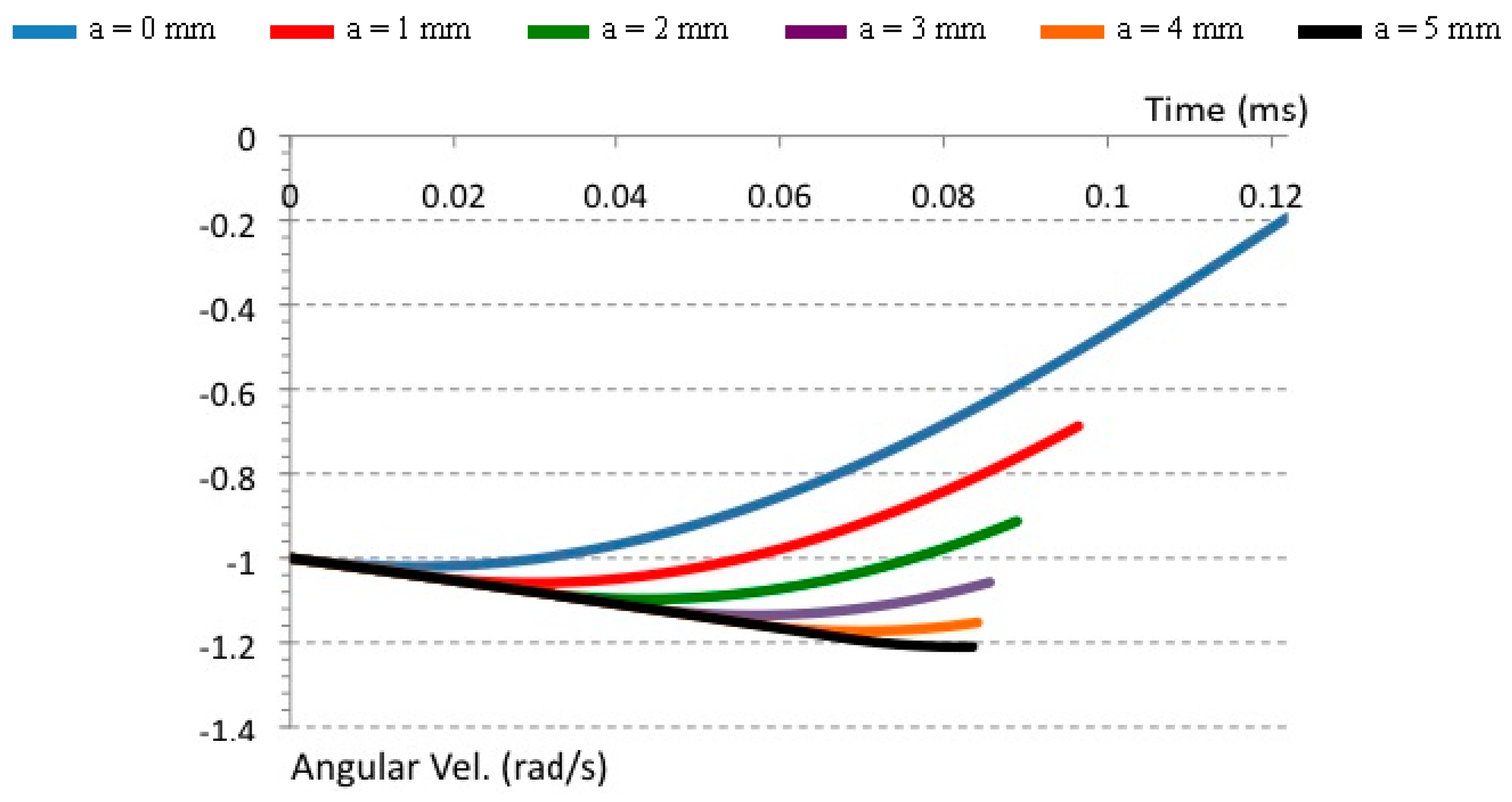
| Offset Position (mm) | 0 | 1 | 2 | 3 | 4 | 5 |
|---|---|---|---|---|---|---|
| Calculated Angular Velocity (rad/s) | −0.227097328 | −0.694595247 | −0.916121086 | −1.05925401 | −1.153553725 | −1.2104872 |
| Measured Angular Velocity (rad/s) | −0.193321433 | −0.687496608 | −0.912832568 | −1.057248583 | −1.152552058 | −1.21005868 |
5.2. Foot Touchdown

5.3. Single Support Rebound

5.4. Single Support Preload
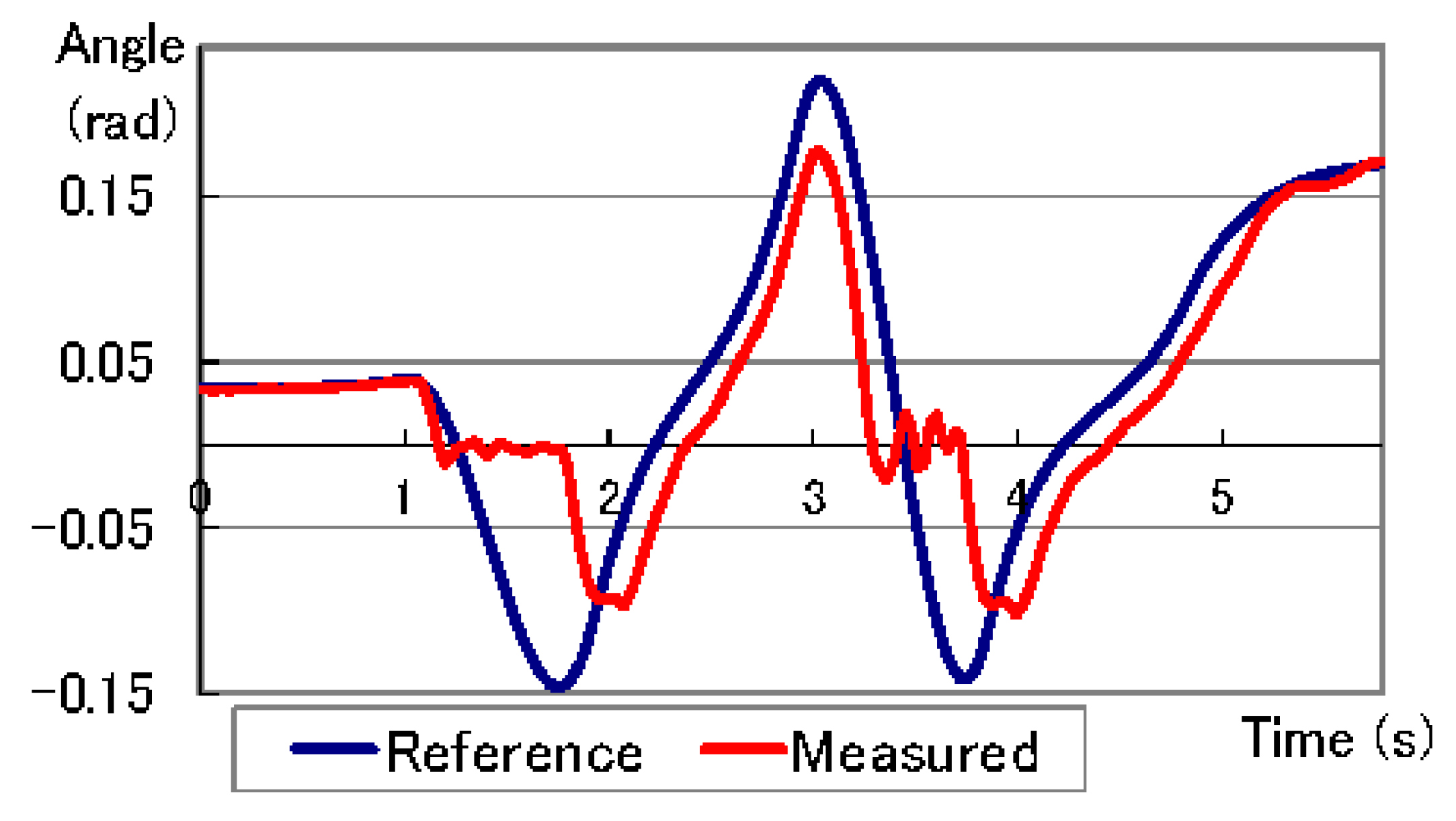
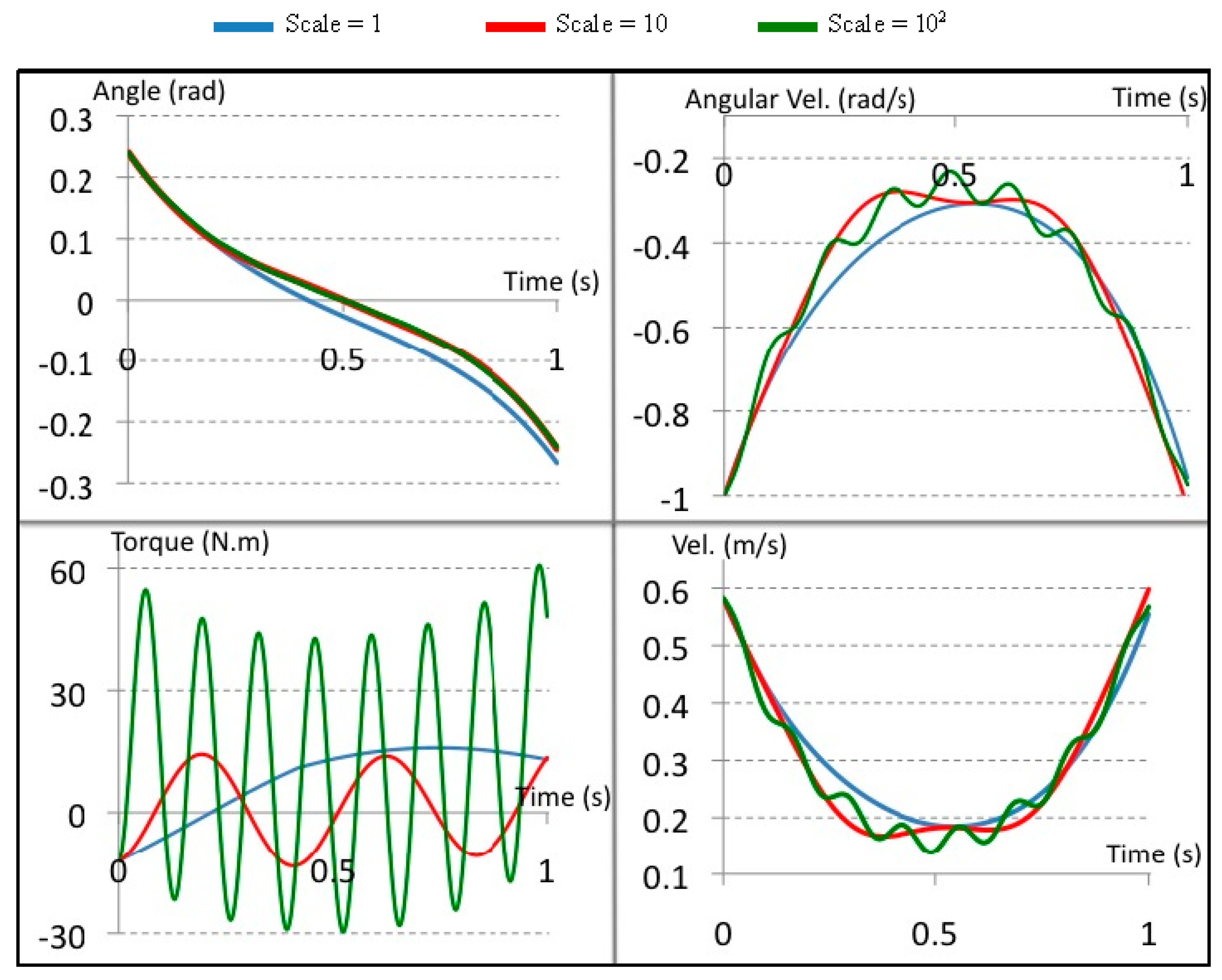
6. Simulation Analysis
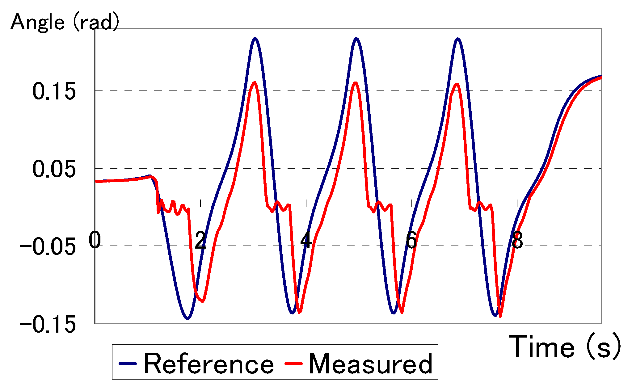
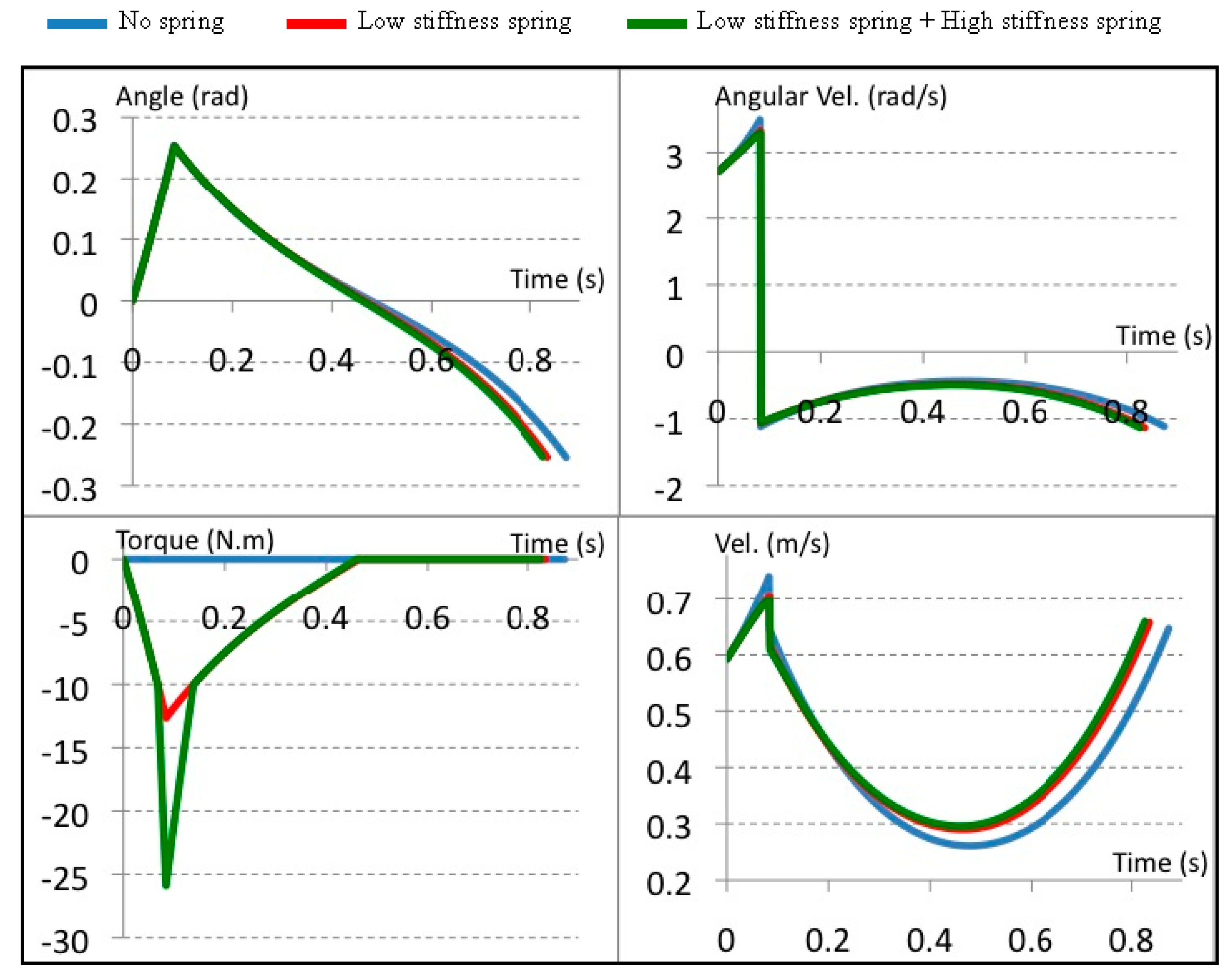
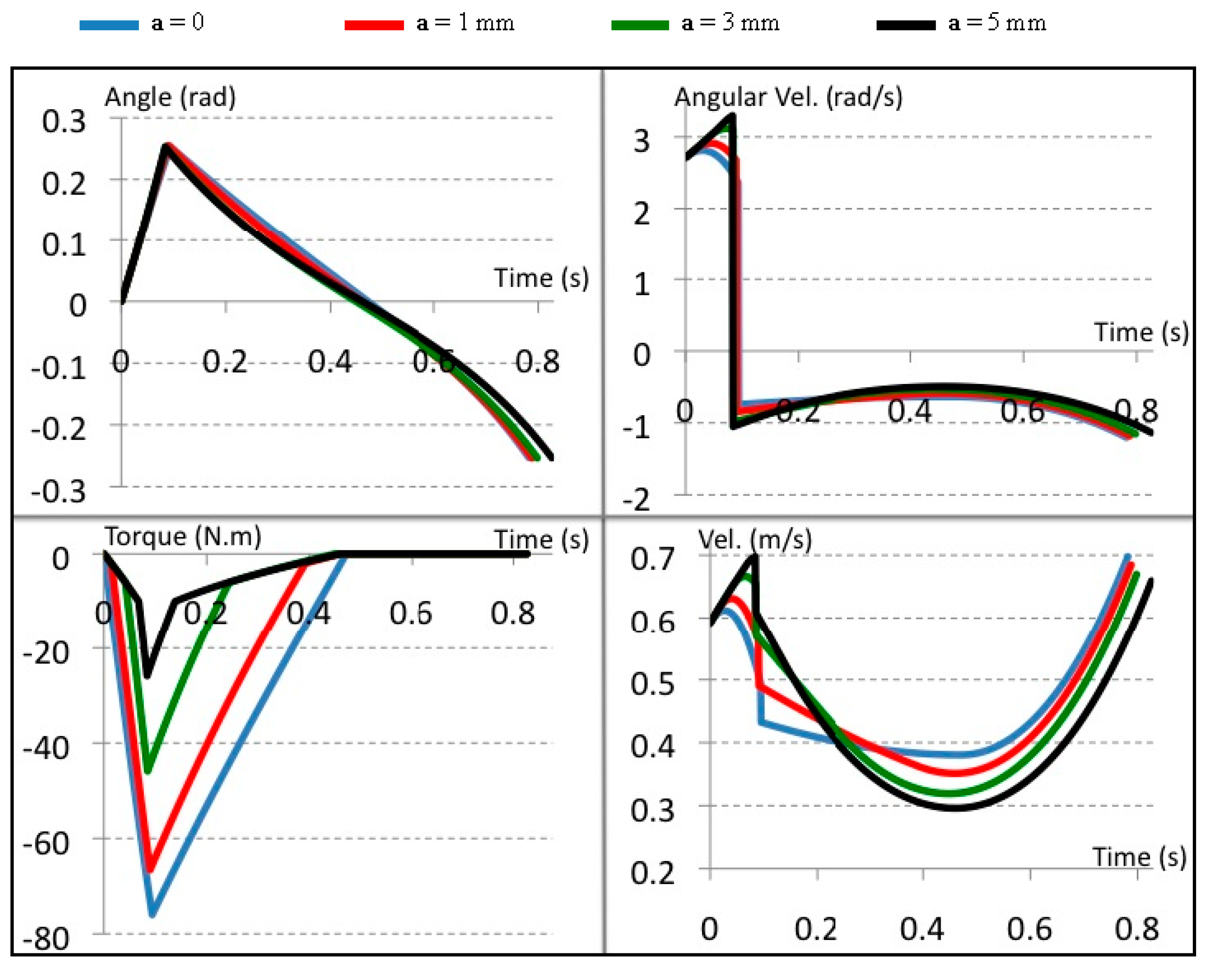
6.1. Evaluating the Mechanism Performance in a Uni-Directional


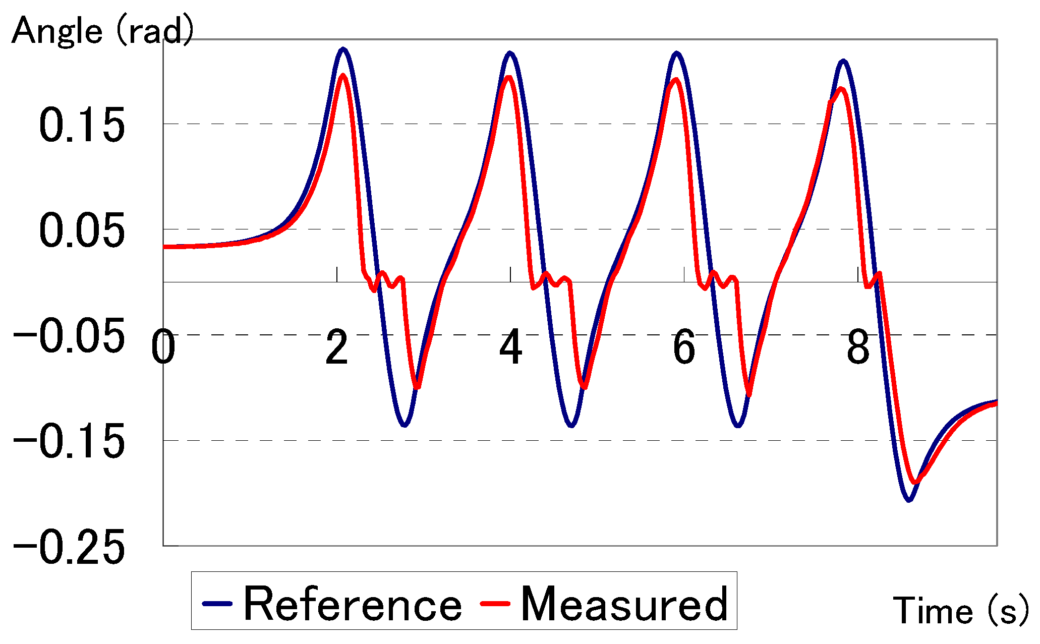
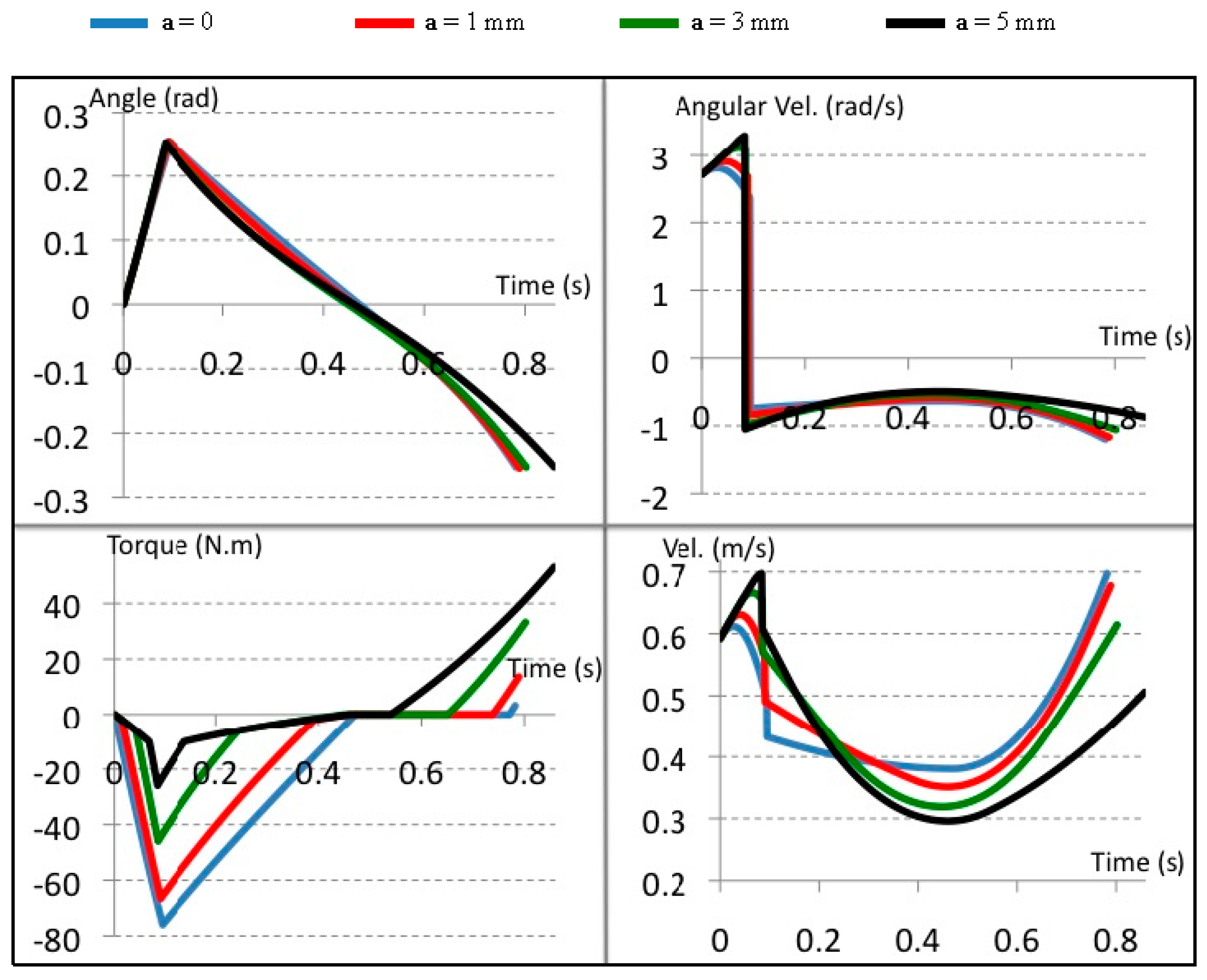
6.2. Evaluating the Mechanism Performance in a Bi-Directional


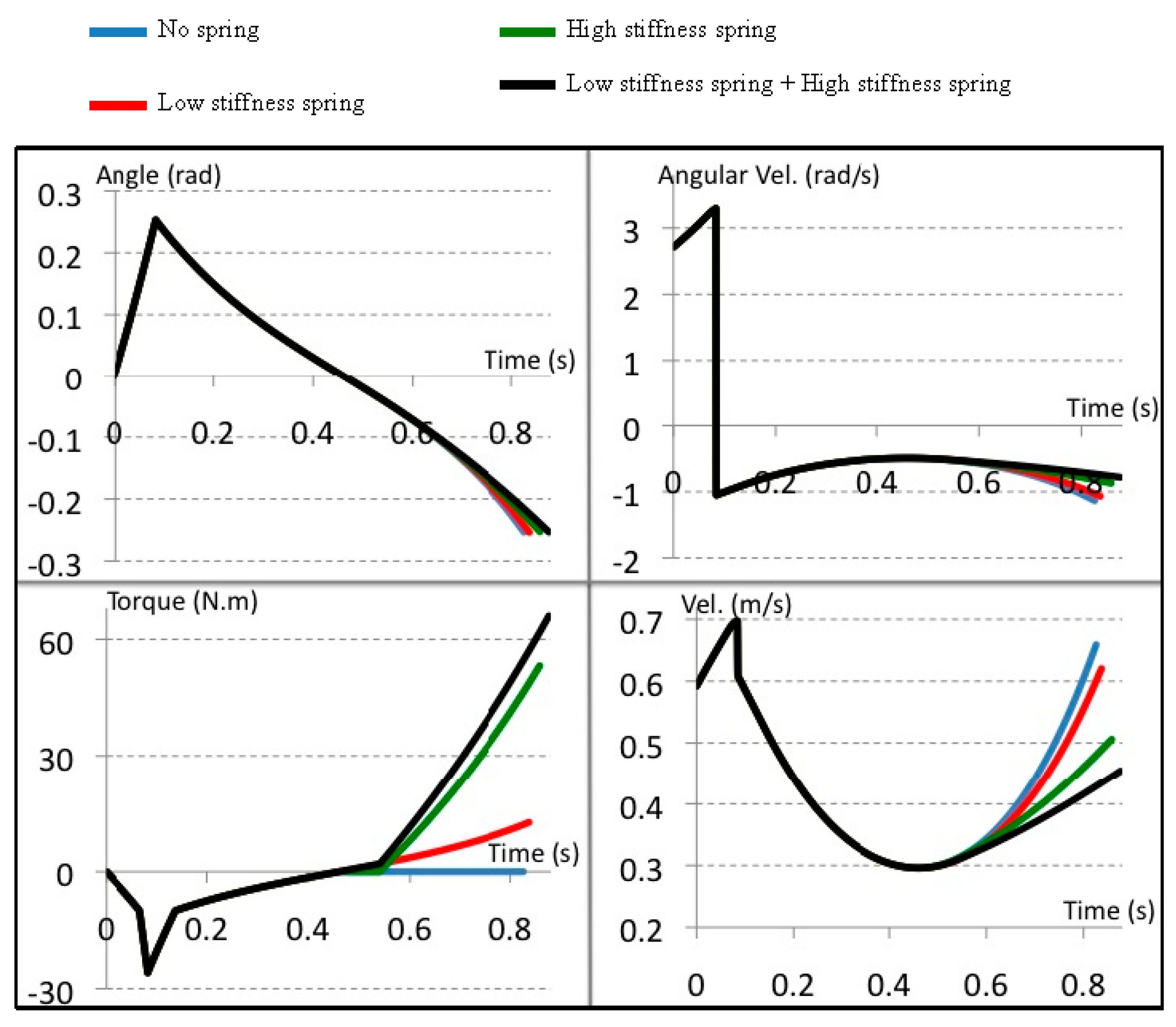
6.3. Evaluating the Mechanism Performance in an Active Mode Control


7. Implementation Challenges

8. Conclusions and Future Work
Author Contributions
Conflicts of Interest
References
- Fukuda, T.; Hasegawa, Y.; Sekiyama, K.; Aoyama, T. Multi-Locomotion Robotic Systems; Springer Berlin Heidelberg: Berlin, Germany; Heidelberg, Germany, 2012. [Google Scholar]
- Kajita, S.; Hirukawa, H.; Harada, K.; Yokoi, K. Introduction to Humanoid Robotics; Springer: Berlin, Germany; Heidelberg, Germany, 2014. [Google Scholar]
- Sakagami, Y.; Watanabe, R.; Aoyama, C.; Matsunaga, S.; Higaki, N.; Fujimura, K. The intelligent ASIMO: System overview and integration. In Proceedings of the IEEE/RSJ International Conference on Intelligent Robots and Systems 2002, Piscataway, NJ, USA, 20 September–4 October 2002; pp. 2478–2483.
- Cho, B.-K.; Kim, J.-H.; Oh, J.-H. Online Balance Controllers for a Hopping and Running Humanoid Robot. Adv. Robot. 2011, 25, 1209–1225. [Google Scholar] [CrossRef]
- Kajita, S.; Espiau, B. Legged Robots. In Handbook of Robotics; Springer: Berlin, Germany; Heidelberg, Germany, 2008; Part B; pp. 361–389. [Google Scholar]
- Omer, A.M.M.; Ogura, Y.; Kondo, H.; Morishima, A.; Carbone, G.; Ceccarelli, M.; Lim, H.-O.; Takanishi, A. Development of a Humanoid Robot Having 2-DOF Waist and 2-DOF Trunk. In Proceedings of the Humanoid 2005 Conference, Tsukuba, Japan, 5 December 2005.
- McGeer, T. Passive dynamic walking. Int. J. Robot. Res. 1990, 9, 62–82. [Google Scholar] [CrossRef]
- Coleman, M.; Ruina, A. An uncontrolled toy that can walk but cannot stand still. Phys. Rev. Lett. 1998, 80, 3658–3661. [Google Scholar] [CrossRef]
- Garcia, M.S. Stability, Scaling, and Chaos in Passive Dynamic Gait Models. Ph.D. Thesis, Cornell University, Ithaca, NY, USA, 1999. [Google Scholar]
- Collins, S.H.; Wisse, M.; Ruina, A. A three-dimensional passive-dynamic walking robot with two legs and knees. Int. J. Robot. Res. 2001, 20, 607–615. [Google Scholar] [CrossRef]
- Wisse, M.; Frankenhuyzen, J.V. Design and construction of mike; a 2D autonomous biped based on passive dynamic walking. In Adaptive Motion of Animals and Machines; Springer: Tokyo, Japan, 2006; pp. 143–154. [Google Scholar]
- Cheng, G.; Hyon, S.-H.; Morimoto, J.; Ude, A.; Hale, J.; Colvin, G.; Scroggin, W.; Jacobsen, S. CB: A humanoid research platform for exploring neuroscience. J. Adv. Robot. 2007, 21, 1097–1114. [Google Scholar] [CrossRef]
- Sugimoto, N.; Morimoto, J.; Hyon, S.-H.; Kawato, M. The eMOSAIC model for humanoid robot control. Neural Netw. 2012, 30, 8–19. [Google Scholar] [CrossRef] [PubMed]
- Verrelst, B.; van Ham, R.; Vanderborght, B.; Vermeulen, J.; Lefeber, D.; Daerden, F. Exploiting adaptable passive behaviour to influence natural dynamics applied to legged robots. Robotica 2005, 23, 149–158. [Google Scholar] [CrossRef]
- Vanderborght, B. Dynamic Stabilisation of the Biped Lucy Powered by Actuators with Controllable Stiffness; Springer: Berlin, Germany; Heidelberg, Germany, 2010. [Google Scholar]
- Wisse, M. Essentials of Dynamic Walking: Analysis and Design of Two-Legged Robots. Ph.D. Thesis, T.U. Delft, Delft, The Netherlands, 2004. [Google Scholar]
- Dickinson, M.H.; Farley, C.T.; Full, R.J.; Koehl, M.A.R.; Kram, R.; Lehman, S. How Animals Move: An Integrative View. Science 2000, 288, 100–106. [Google Scholar] [CrossRef] [PubMed]
- Rosenbaum, D.A. Human Motor Control; Academic Press: Cambridge, MA, USA, 2009. [Google Scholar]
- Winter, D.A. Biomechanics and Motor Control of Human Movement; Wiley: Hoboken, NJ, USA, 2009. [Google Scholar]
- Ishikawa, M.; Komi, P.V.; Grey, M.J.; Lepola, V.; Bruggemann, G.-P. Muscle-tendon interaction and elastic energy usage in human walking. J. Appl. Physiol. 2005, 99, 603–608. [Google Scholar] [CrossRef] [PubMed]
- Biewener, A.A.; Farley, C.T.; Roberts, T.J.; Temaner, M. Muscle mechanical advantage of human walking and running: Implications for energy cost. J. Appl. Physiol. 2004, 97, 2266–2274. [Google Scholar] [CrossRef] [PubMed]
- Omer, A.M.M.; Ghorbani, R.; Lim, H.-O.; Takanishi, A. Simulation of Semi-Passive Dynamic Walking for Humanoid Robots. In Proceedings of the 8th International Conference on Humanoid Robot, Daejeon, Korea, 1–3 December 2008; pp. 541–544.
- Omer, A.M.M.; Ghorbani, R.; Lim, H.-O.; Takanishi, A. Semi-Passive Dynamic Walking for Biped Walking Robot Using Controllable Joint Stiffness Based on Dynamic Simulation. In Proceedings of the International Conference on Advanced Intelligent Mechatronics, Singapore, 14–17 July 2009; pp. 1600–1605.
- Omer, A.M.M.; Ghorbani, R.; Lim, H.-O.; Takanishi, A. Simulation based study of a semi-passive dynamic walking for a human size humanoid robot. In Proceedings of the 12th International Conference on Climbing and Walking Robots and the Support Technologies for Mobile Machines, Istanbul, Turkey, 9–11 September 2009; pp. 653–660.
- Omer, A.; Sulaiman, T.; Ghorbani, R.; Hashimoto, K.; Lim, H.-O.; Takanishi, A. Development of Adjustable Stiffness Mechanism for Bipedal Walking Robot. In Proceedings of the 2nd IFToMM Asian Conference on Mechanism and Machine Science, Tokyo, Japan, 12–14 November 2012. Paper ID 117.
- Koganezawa, K.; Matsumoto, O. Active/passive hybrid walking by the biped robot TOKAI ROBO-HABILIS 1. In Proceedings of the IEEE/RSJ International Conference on Intelligent Robots and Systems, Lausanne, Switzerland, 30 September–4 November 2002; pp. 2461–2466.
- Rouse, E.J.; Mooney, L.M.; Herr, H.M. Clutchable series-elastic actuator: Implications for prosthetic knee design. Int. J. Robot. Res. 2014, 33, 1611–1625. [Google Scholar] [CrossRef]
© 2015 by the authors; licensee MDPI, Basel, Switzerland. This article is an open access article distributed under the terms and conditions of the Creative Commons by Attribution (CC-BY) license (http://creativecommons.org/licenses/by/4.0/).
Share and Cite
Omer, A.; Ghorbani, R.; Hashimoto, K.; Lim, H.-o.; Takanishi, A. A Novel Design for Adjustable Stiffness Artificial Tendon for the Ankle Joint of a Bipedal Robot: Modeling & Simulation. Machines 2016, 4, 1. https://doi.org/10.3390/machines4010001
Omer A, Ghorbani R, Hashimoto K, Lim H-o, Takanishi A. A Novel Design for Adjustable Stiffness Artificial Tendon for the Ankle Joint of a Bipedal Robot: Modeling & Simulation. Machines. 2016; 4(1):1. https://doi.org/10.3390/machines4010001
Chicago/Turabian StyleOmer, Aiman, Reza Ghorbani, Kenji Hashimoto, Hun-ok Lim, and Atsuo Takanishi. 2016. "A Novel Design for Adjustable Stiffness Artificial Tendon for the Ankle Joint of a Bipedal Robot: Modeling & Simulation" Machines 4, no. 1: 1. https://doi.org/10.3390/machines4010001
APA StyleOmer, A., Ghorbani, R., Hashimoto, K., Lim, H.-o., & Takanishi, A. (2016). A Novel Design for Adjustable Stiffness Artificial Tendon for the Ankle Joint of a Bipedal Robot: Modeling & Simulation. Machines, 4(1), 1. https://doi.org/10.3390/machines4010001