Abstract
Previous experimental knowledge has confirmed that one of the most influential factors affecting the performance of polymer friction absorbers embedded in buffer housing as part of the buffer and chain coupler is the temperature. This paper defines a mathematical model of a friction-type polymer absorber, PMKP-110. The presented mathematical model specifically includes the influence of the environment temperature on the dynamic impact curve for −60 °C and 15 °C. The dependence between the initial pre-tension of the buffer and the ambient temperature is calculated. The model involves an equation of motion for moving parts of the absorber, and the solution of the differential equation is achieved in Matlab. Results are given as diagrams of the impact deformation and impact speed of the polymer block, with assumed zero initial impact speed. The model can be used to analyze the action of the longitudinal forces that occur during transient conditions of the movement of the carriages.
1. Introduction
Rail freight holds an important place in the transport system of any country in the world. The increase of goods transport in recent years has accordingly led to increased speed and weight of the carriages. Thus, when maneuvering or forming rail carriage compositions at sort stations, the increasing impact speed between carriages is an issue. The weight significantly increases the magnitude of the longitudinal forces acting between carriages. As a result, the occurrence of massive repairs increases, which appreciably reduces the income made from goods transport. Research and analyses of longitudinal train dynamics have a significant role in the improvement of the general comfort of passengers as well as implications for freight product damage, vehicle stability, rolling stock design, and rolling stock metal fatigue [1,2].
One of the most difficult and also very important tasks in longitudinal train dynamics is the modeling of draft gears, which is a highly nonlinear problem complicated by an extensive number of factors: nonlinear stiffness, friction, coupler slack, pre-load, and so on. The poor predictability, repeatability, and the discontinuity of friction make this task more challenging; a detailed review of techniques in dynamics modeling of friction draft gears was given in Reference [3]. The modeling part is mainly focused on the inter-wagon connections with a briefer treatment of the other force inputs: traction, dynamic braking, air braking, grades, rolling, and air resistance. The non-linearity of the wagon connections involving draft gears or buffers and draw gear components needs to be modeled accurately to achieve representative results for force transients and accelerations [4]. Polymer draft gears were modeled in Reference [5], where impact characteristics, in-train characteristics, and frequency responses of these polymer draft gears were studied and compared with those of a friction draft gear. The impact simulations showed that polymer draft gears give higher loading trajectories for higher impact velocities, while friction draft gears have the opposite tendency. Longitudinal train dynamics simulations show that polymer draft gears have significantly longer deflections than friction draft gears in normal train operations. A white-box friction draft gear model was developed in References [6,7], featuring the transitional characteristic based on the determination of draft gear housing deformation obtained from the finite element analysis for the draft gear PMKP-110 during impact. The conventional two-stage working process—the loading and unloading of the friction draft gear—was detailed as a four-stage process in Reference [7] and the base model was improved with regard to force–displacement characteristics, friction modeling, and transitional characteristics considering all components and their geometries in the draft gear. Further, the main differences between the one-to-one shunting impact and the impact of long groups of cars in terms of features of the draft gear deflections and the coupler force time history are discussed in Reference [8]. Draft gear velocities, displacements, and coupler forces in shunting impacts of long groups of cars were analyzed, and it was revealed that the bearing structures of the cars and the cargo are subjected to principally different loading conditions compared to the case of one-to-one shunting impacts.
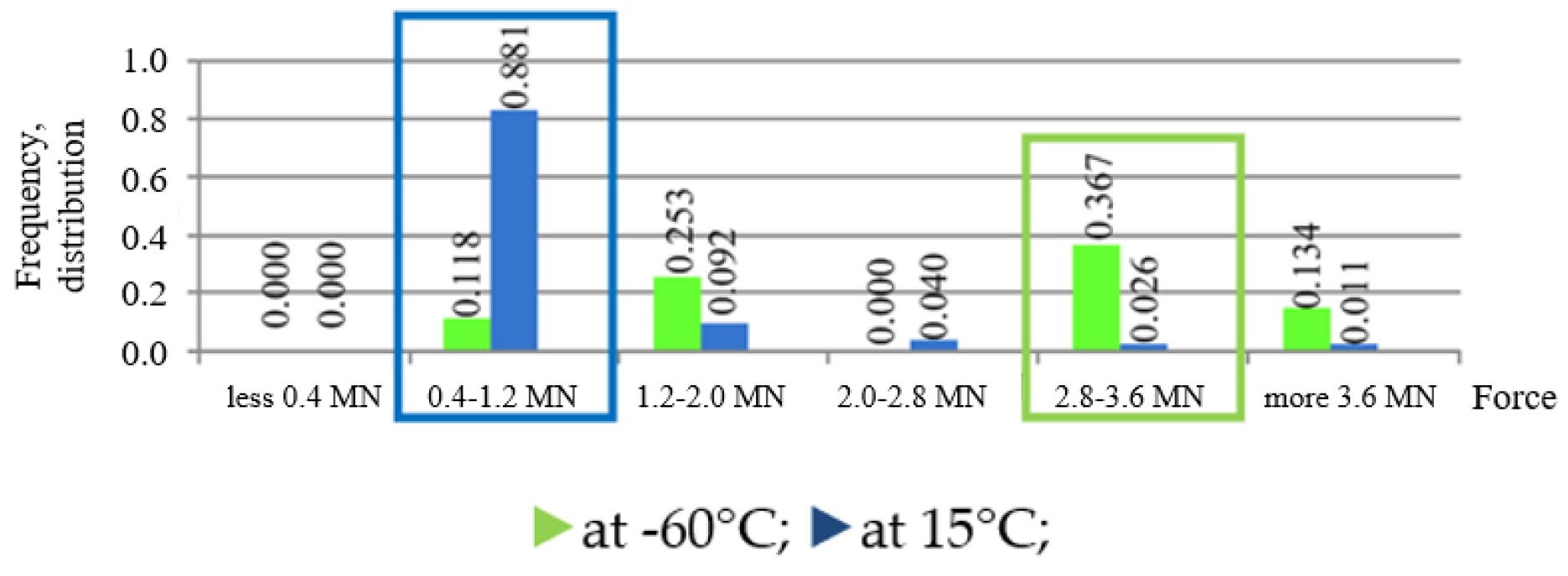
To calculate the reliability and service life of the buffering device elements, the optimal parameters of the bumpers should be known. Therefore, the statistical distribution of the longitudinal forces that transfer through the bumpers is employed. The calculated distribution of the extreme forces is given in Figure 1 [9,10].

Figure 1.
Distribution of the longitudinal forces that transfer through the bumpers.
Recorded results show a noticeable difference between the statistical distribution for low and normal temperatures. It is obvious that low temperatures essentially affect the characteristics of the friction-polymer bumpers. Therefore, the speed regime should be strictly followed during maneuver operations at sort stations.
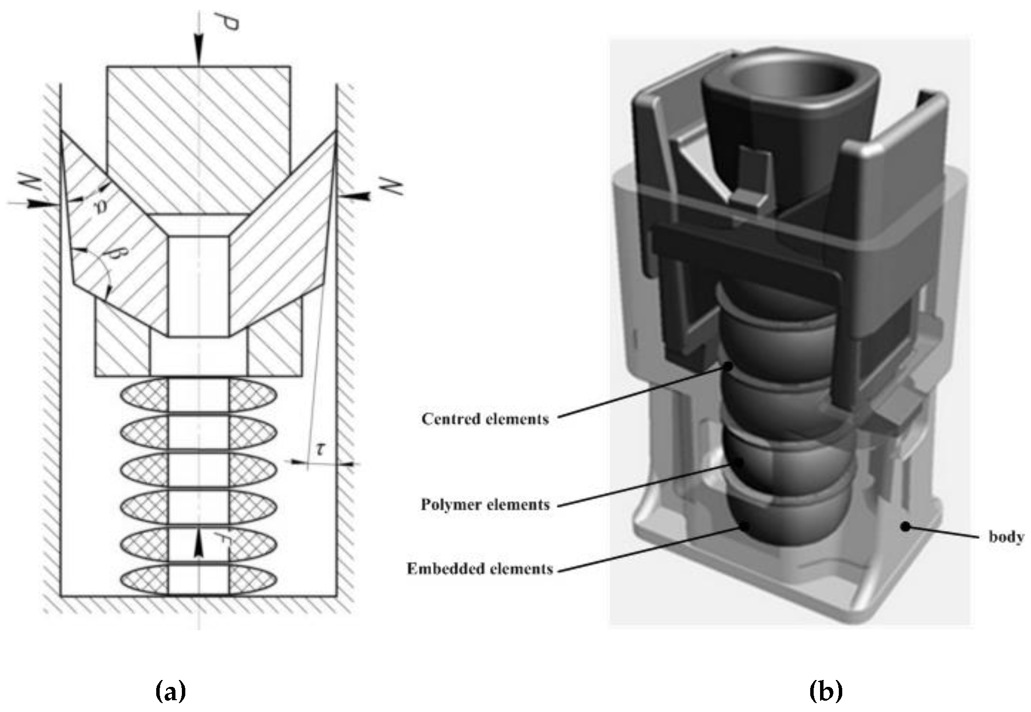
Because of this role, in recent years new design solutions have been developed [11] in which the absorption capacity for longitudinal forces is obtained with a package made of polymer material embedded in the buffer. This is achieved by increasing the rigidity of the support block, which leads to a reduction of the angles of the tapered corners of the buffer, thus reducing the friction between auxiliary surfaces (Figure 2a). The damping properties of polymers also help to reduce the self-induced vibration that appears in shock (impact) compression. The principle scheme of the elastic-friction absorption device (buffer assembly) with a package of five polymer components is given in Figure 2.
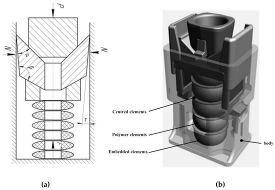
Figure 2.
Elastic-frictional absorption device principle scheme (a) with package of polymer elements (b).
The error of the calculated force does not exceed more than 5% compared to the maximum force. In addition, the calculated displacement does not exceed more than 1% error compared to the maximum displacement. These margins of error thus adhere to the strict UIC (International Railway Union) requirements [12] for buffer and chain coupler devices.
For freight carriages and locomotives, it is required that, for forces smaller than 2.0 MN, the energy absorber achieve a capacity of no less than 70 kJ, and at full displacement or forces less than 3.0 MN, a capacity of no less than 90 kJ. Therefore, if the supporting polymer block has insufficient rigidity, the required energy capacity will not be achieved. Also, if the rigidity is increased, it will cause an increase in compressive force. Therefore, the determination of the stiffness curve of the support polymer block is an important and challenging task.
This paper defines a mathematical model of a friction-type polymer absorber (PMKP-110), taking into account the influence of the environment temperature on the dynamic impact curve for −60 °C and 15 °C. The model constitutes an equation of motion for moving parts of the absorber, and the solution of the differential equation is achieved using Matlab. Results are given as diagrams of the impact deformation and impact speed of the polymer block, with an assumed zero initial impact speed. The model can be used to analyze the action of the longitudinal forces that occur during transient conditions of the movement of the carriages. In following section, we describe the experimental setup and the determination of absorber curves. The subsequent section outlines the mathematical model of the dynamic behavior of the buffer, taking into account the temperature factor. Finally, the last two sections discuss the obtained results and provide conclusions, respectively.
2. Experimental Determination of Absorber Curves
The PMKP-110 draft gear is a highly efficient shock damper with an increased capacity of T1 grade, which is designed for the protection of multipurpose versatile freight cars against axial load impact and widely applied in the railway industry in Kazakhstan, Russia, Belarus, and Ukraine. This device was developed on the basis of the commercially produced draft gear (PMK-110), which contains a retaining return device represented by a set of polymer elastic blocks [13] instead of a spring set. The production of the PMKP-110 cast housings applies the technology of casting using cold-forming mixtures. Such technology provides the required surface quality, absence of burning-in while casting, and dimension accuracy of the cast housing. The Ukrainian Casting Company-ULK (Kharkov, Ukraine) where the PMKP-110 housings are manufactured, is equipped with automatic molding line OMEGA (Peterborough, UK) and induction melting furnace EGES (Istanbul, Turkey). This device is certified according to the UkrSEPRO System and Certification System for Federal Railway Transport.
The use of elastomer parts provides an improved F–D curve and an enhanced energy absorption capacity of the device. The increase of the stiffness of the elastic set reduces the directional angles of the wedge system, which helps to stabilize the friction at the contact surfaces; the damping properties of the elastomer reduce self-excited frictional vibrations, which take place under impact compression [6].
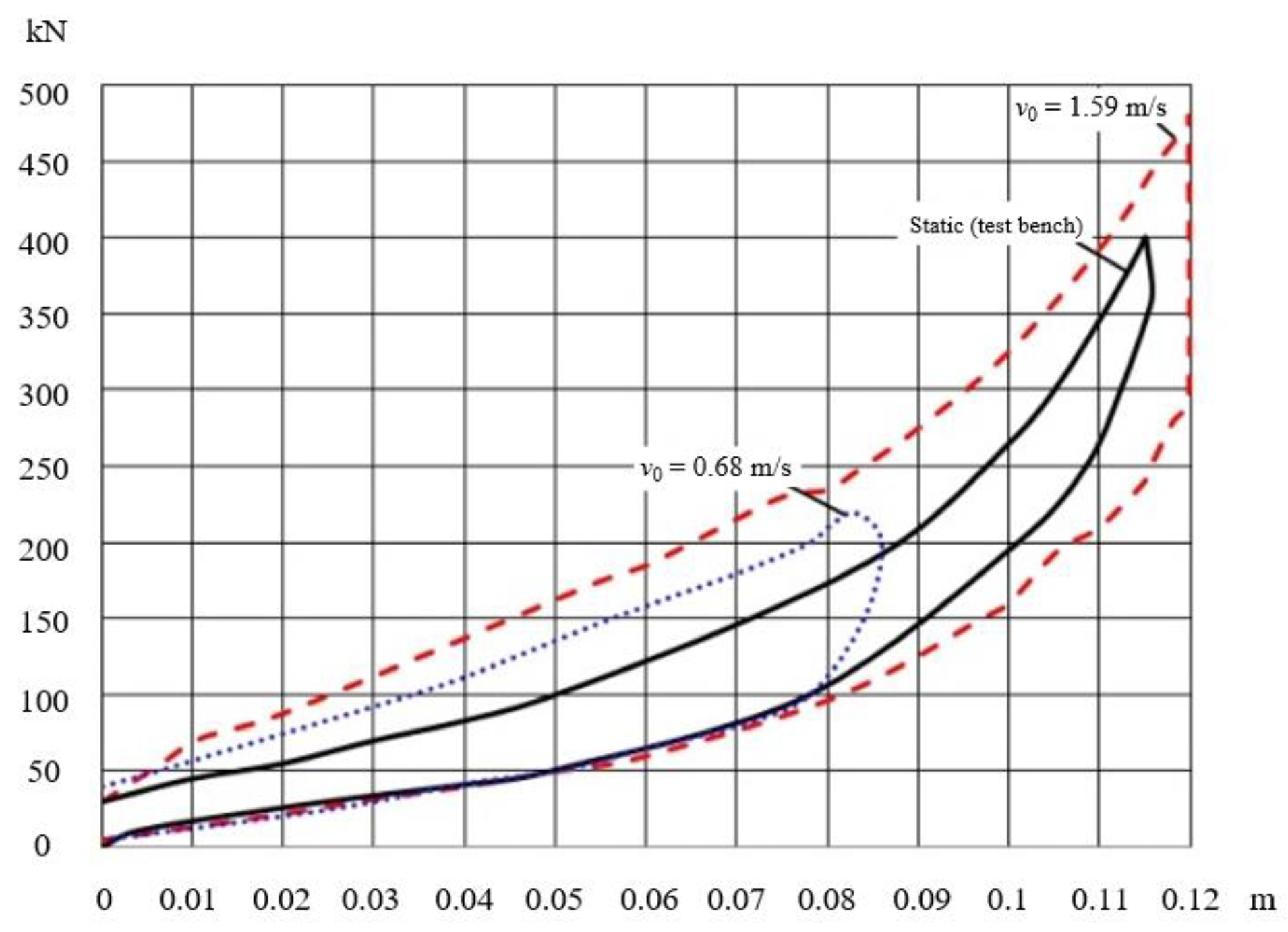
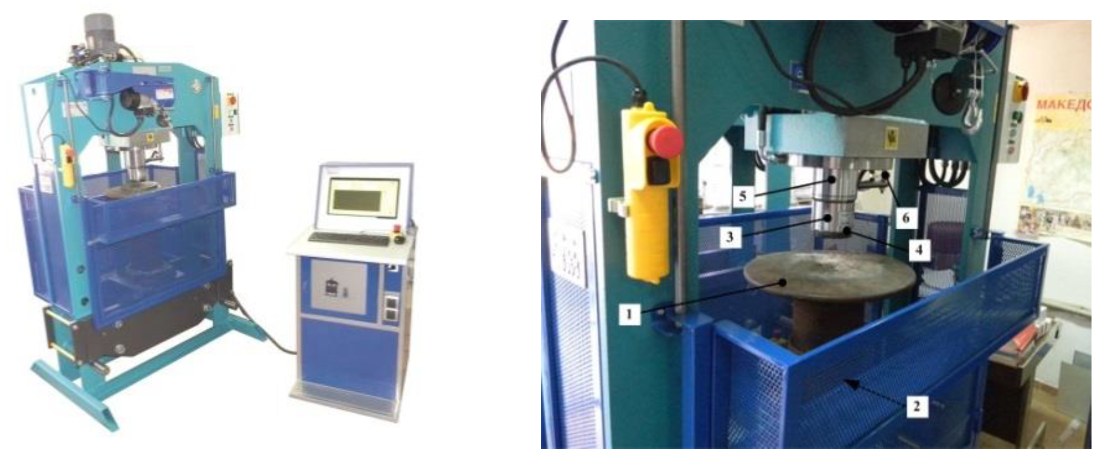
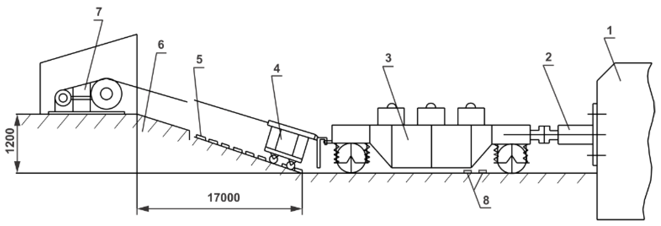
Experimental testing [14] of PMKP-110 buffer was conducted in order to obtain several parameters such as the static force–deformation curve, the temperature influence (from −60 to +51 °C) on the static curve (Figure 3), and the dynamic change of the force of the polymer package at different shock (impact) speeds (Figure 4). The buffer was placed in an isolated tank filled with alcohol and cooled by dissolving carbon dioxide. Continuous monitoring of the ambient temperature was carried out with a thermometer. After achieving the required temperature and maintaining these conditions for 20–30 min, the buffer was installed on the test bench, where the static characteristic of the buffer and related diagram was obtained. The scheme of the test machine used for static testing is shown in Figure 5. The buffer is marked with (1). The buffer stands on support (2). The compressive piston (3) has strain gauges (4) and also works as a load cell. Above the piston is the hydraulic cylinder (5). Displacement (deformation) is registered with a linear transducer, marked with (6). The housing is made of steel St37-2 and the cone elements are made of metal ceramic. The speed of buffer compression is 1–2 mm/s. The error of the experimental and the mathematical data is a maximum of 4%. The buffer was tested on a real railway model in scale 1:1 according to Reference [15]. Test layout is shown in Figure 6 and the recorded results are given as a force–deformation curve in Figure 4.
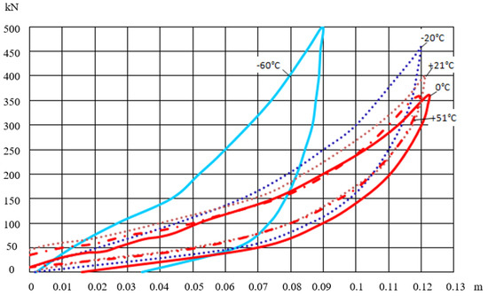
Figure 3.
Static force–deformation curve of the polymer block of PMKP-110 buffer as f (T °C).
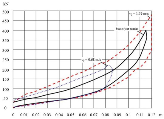
Figure 4.
Dynamic force–deformation curve of the polymer pack for different impact speeds, —Static (test bench), --v0 = 1.59 m/s, ···v0 = 0.68 m/s.

Figure 5.
Compressive test bench for buffer static testing.

Figure 6.
Testing buffer on a real railway model with impact.
The impact cart (3) with a mass of 44 t is positioned on the steep (6) with a pulling device (7) and then set at a particular height (5), depending on the required impact speed. The cart is then released and strikes the support (2), which is firmly attached to the massive concrete wall (1). The impact speed is fixed with poles (8).
The test apparatus was installed to be stationary on the support wall, and a loaded cart was used as a stiff rod that strikes the buffer. The measuring bridge MIC-026 registered the time and change of compression force and the stroke of the device at different impact speeds. The registration of forces was achieved by means of an automatic dynamometer assembly with a tensoresistant sensor. The buffer stroke was measured with a large displacement transducer.
3. Mathematical Model
With the results from the experiments, a mathematical model was created for the static curve of the polymer block embedded in the buffer. The model takes into account the temperature factor of the environment with a polynomial of the fifth degree [16].
It has been experimentally determined that for a temperature of +15 °C, the fifth-degree polynomial has the following form:
For a temperature of −60 °C, the polynomial has the following form:
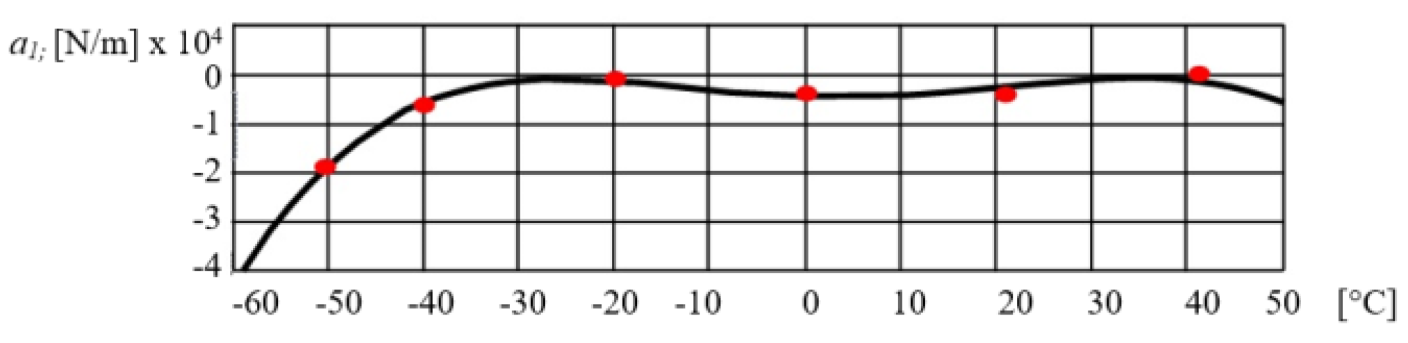
Polynomial coefficients for different temperatures from Equation (1) are given in Table 1, and Figure 7 gives the variation of coefficient a1 as a function of the temperature.

Table 1.
Polynomial coefficients for different temperatures.
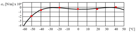
Figure 7.
Dependence of a1 of temperature.
Depending on the temperature coefficients, by using the method of least squares, the analytical solution is obtained and included in the existing mathematical model of the PMKP-110 buffer, given by Equation (4) [17]:
where x is the displacement of the absorber, is the velocity of the absorber, a is the displacement of the first degree, c is the stiffness of the absorber body, is the transfer coefficient, is the transfer coefficient without friction, is the maximal stroke of the absorber, is the maximum stroke at a given situation, and is the dynamic characteristic of the support block of the absorber.
The dynamic characteristic of the support block of the absorber given in Equation (4) is [18]:
The coefficients are given with Equation (5):
The coefficients given in Equation (4) depend on the temperature of the working environment. With their replacement in Equation (5), the dynamic stiffness characteristics are obtained for the polymer support block that participates in a mathematical model of the PMKP-110 buffer given by Equation (4).
For temperatures of 15 °C (Equation (6)) and −60 °C (Equation (7)), Equation (4) is given with the following expressions:
Due to the abovementioned factors, it is necessary to create a mathematical model of the absorber through which the optimum stiffness curve of the supporting polymer block will be determined.
The differential equation of the moving components of the support block (Figure 2) has the following form [19]:
where x is the displacement of the pressed cone section, is the velocity of the pressed cone, is the acceleration of the pressed cone, and is the transfer coefficient, which shows how much the force of the device (the buffer) P exceeds the pressure of the supporting polymer block F (Figure 3). In this case, = 5.
The calculation of Ψ is contained in Equation (3), which represents the dynamic characteristic of the force of the polymer package composed of five parts made of Durel material. The package has an initial pre-tension of x0 = 90 mm, corresponding to the initial mounting position of the supporting block in the kit.
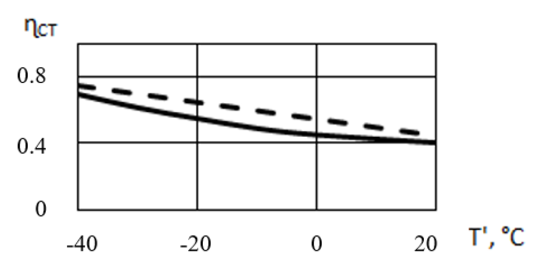
The irreversible energy absorption coefficient in the polymer block at the quasi-static test depends on the type of the buffer and the temperature (Figure 8); usually, it is within the range of 0.4–0.7 [20].
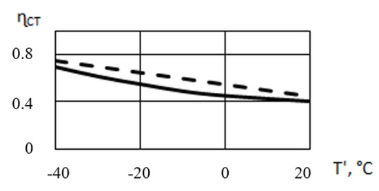
Figure 8.
The irreversible energy absorption coefficient .
The force , expressed in kN, has a nonlinear characteristic and has so far been determined experimentally.
The mass M that causes the impact 44,000 kg is much larger than the buffer absorber. The force P depends on the speed of the system and its position, which are calculated from a known formula [21,22] involving the angles of the conical metal parts and the coefficient of friction between them. Therefore, the force P can be calculated using the second-order Lagrange equation:
By substituting Equation (10) in Equation (9), we obtain:
Substituting Equation (12) in Equation (11), we obtain:
Differential Equation (13) is of the first order, and determines the velocity of movement of the system from the position (x—displacement). The total force acting on the system is determined by the following equation:
By substituting Equation (14) in Equation (13), we obtain the equation of motion (Equation (8)) of the absorber parts of the buffer.
4. Result and Discussion
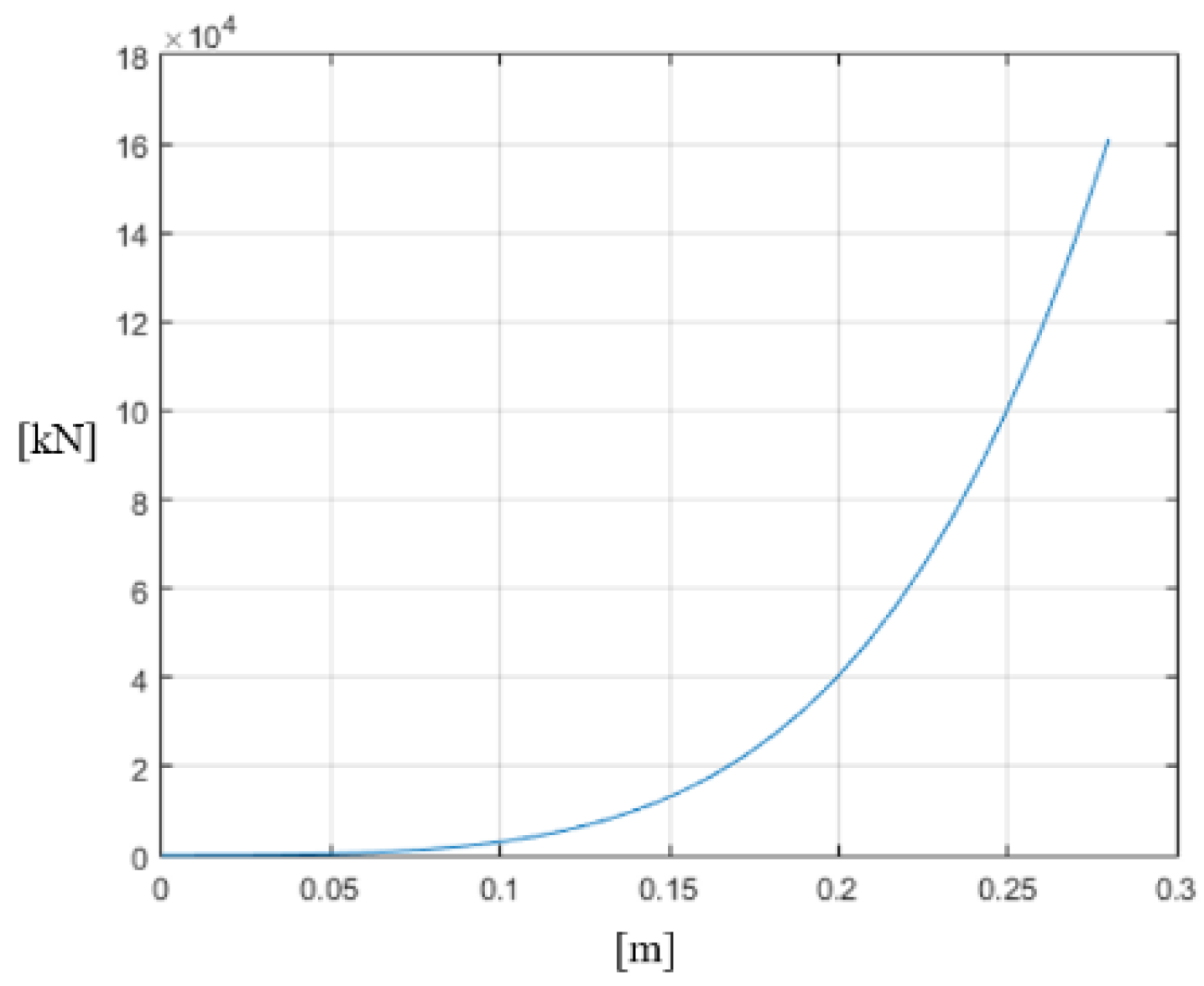
Equations (5)–(8) were solved using the Matlab program package. Figure 9 gives the change in the dynamic force , Equation (6). The displacement and velocity of the movable system (Equation (6)) of the buffer (Equation (8)) for an operating temperature of +15 °C and initial velocities v0 = 1.15 m/s and v0 = 3.5 m/s are given in Figure 10 and Figure 11.
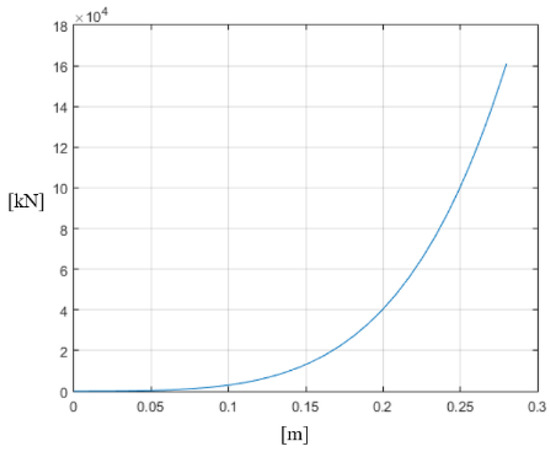
Figure 9.
Change of dynamic force at an operating temperature of +15 °C and .

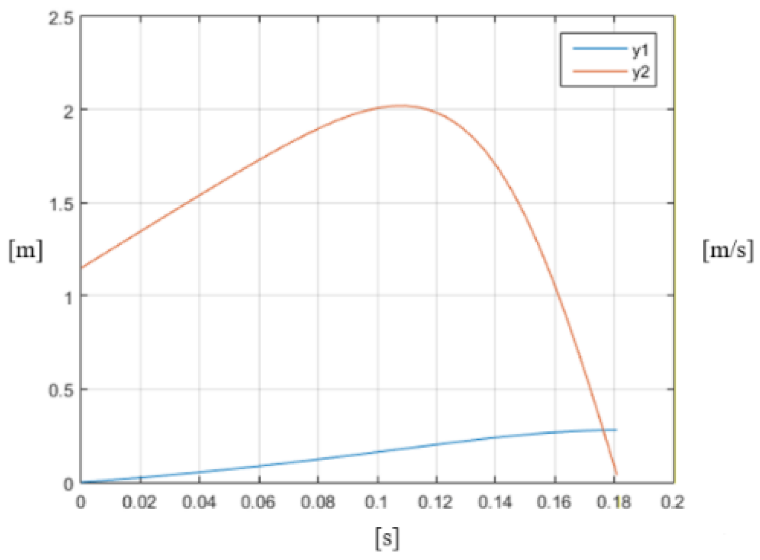
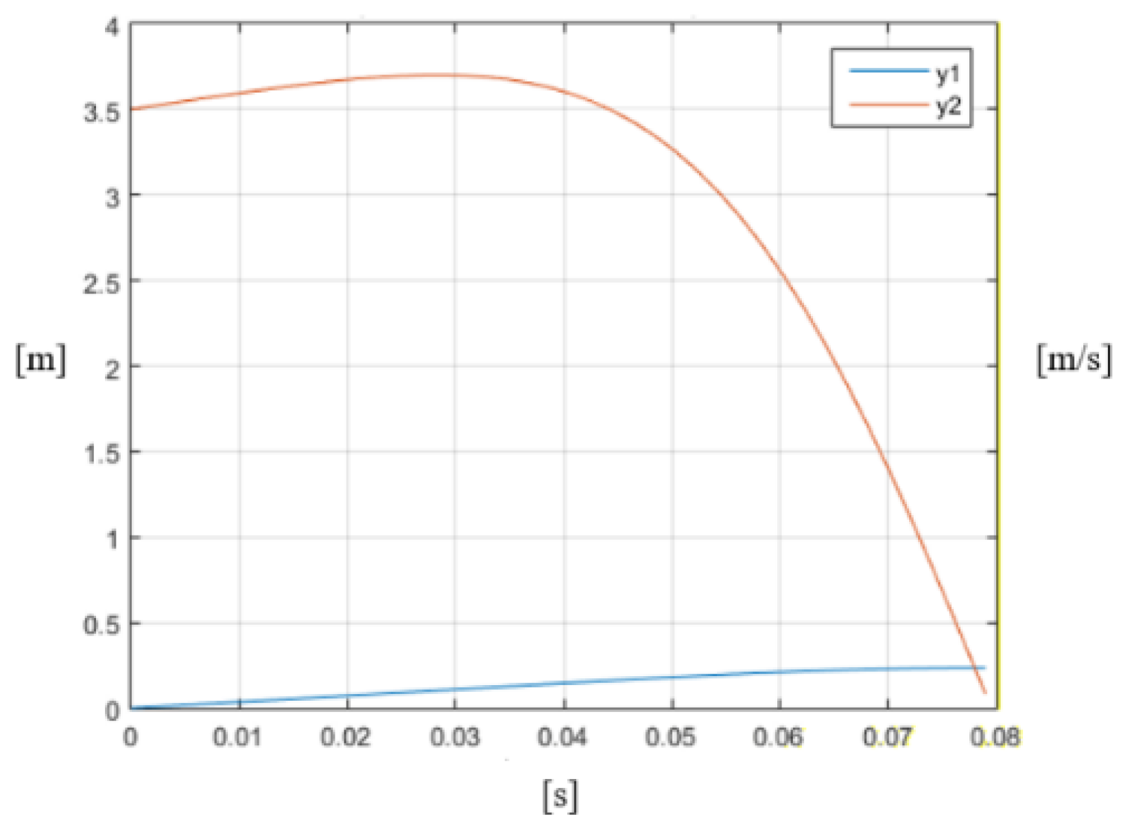
Figure 10.
Displacement (blue line) and velocity of the buffer (orange line) at an operating temperature of +15 °C, an impact speed of v0 = 1.15 m/s, and .
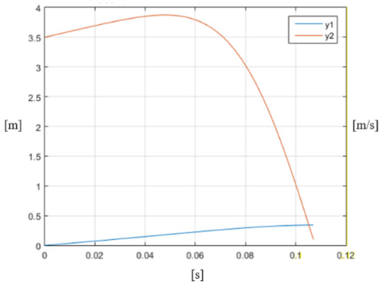
Figure 11.
Displacement (blue line) and velocity of the buffer (orange line) at an operating temperature of +15 °C, an impact speed of v0 = 3.5 m/s, and .
Figure 12 gives the change of dynamic force , as expressed by Equation (7). The displacement and velocity of the movable system (Equation (7)) of the buffer (Equation (8)), for a working temperature of −60 °C and initial velocities v0 = 1.15 m/s and v0 = 3.5 m/s, are shown in Figure 13 and Figure 14, respectively.
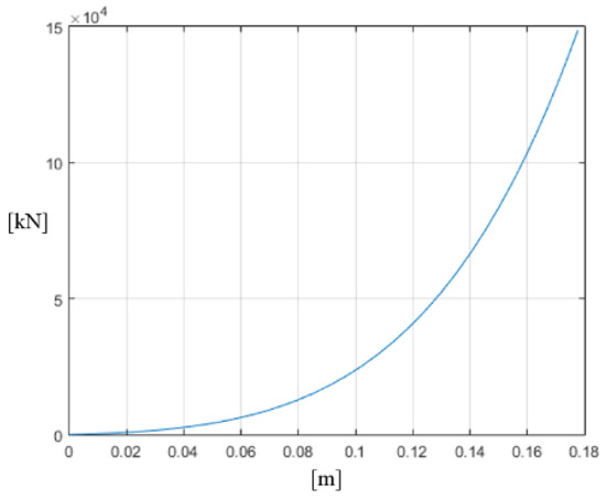
Figure 12.
Change of dynamic force at an operating temperature of −60 °C and .

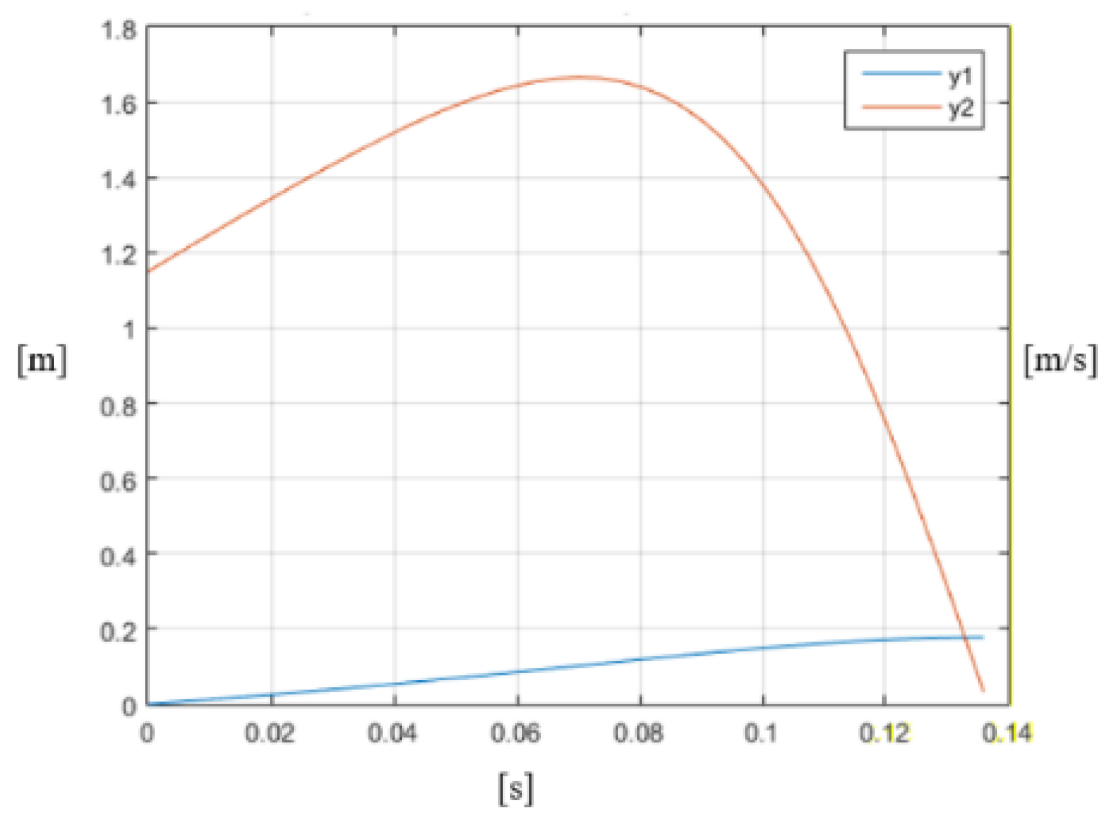
Figure 13.
Displacement (blue line) and velocity of the buffer (orange line) at an operating temperature of −60 °C, an impact speed of v0 = 1.15 m/s, and .
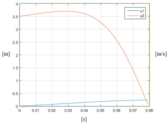
Figure 14.
Displacement (blue line) and velocity of the buffer (orange line) at an operating temperature of −60 °C, an impact speed of v0 = 3.5 m/s, and .
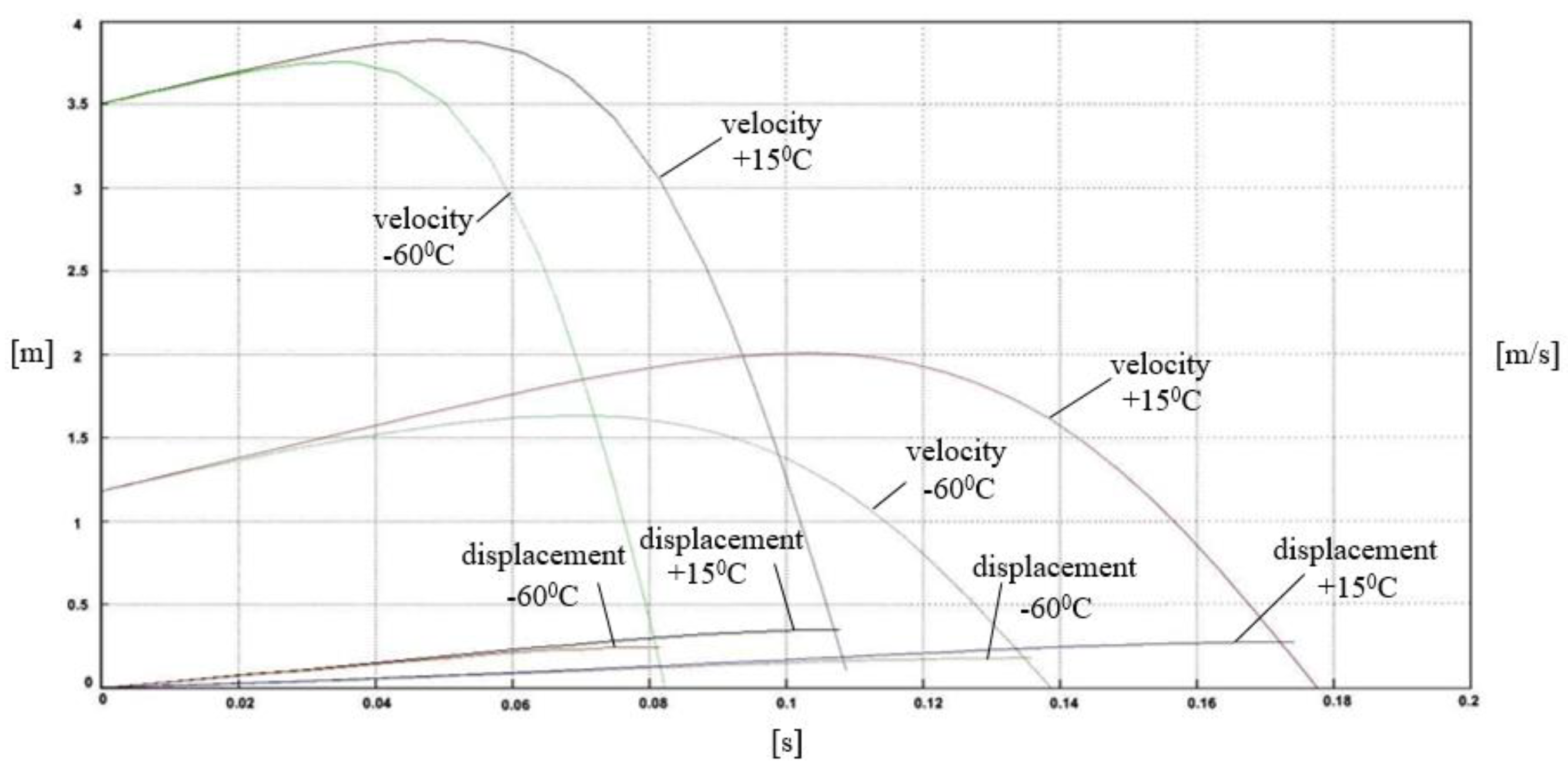
The displacement and velocity of the buffer at different operating temperatures (−60 °C and 15 °C) and different impact speeds (v0 = 1.15 m/s and v0 = 3.5 m/s) are presented in Figure 15. By reducing the impact velocity on the polymer block, the working length and the displacement of the same are reduced. In the operation process, the initial velocity increases at impact and then drops to zero, and at higher speeds the percentage of the increase is lower.
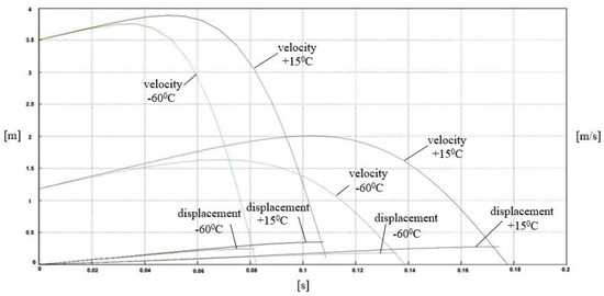
Figure 15.
Displacement and velocity of the buffer at different operating temperatures and different impact speeds.
5. Conclusions
The mathematical model of the PMKP-110 buffer was obtained, taking into account the temperature factor through the dynamic force of the support block of the absorber. The dependence between the initial pre-tension of the buffer and the ambient temperature was calculated. Certain conclusions can be drawn based on the calculations:
- The model can be used to analyze the action of the longitudinal forces that occur during transient conditions of the movement of the carriages.
- The dynamic force obtained for a working temperature of +15 °C is five times greater than the dynamic force obtained for a working temperature of −60 °C. This indicates that the influence of the temperature change is of great importance.
- For a working temperature of +15 °C and a working stroke of 180 mm, it was calculated that ; meanwhile, for a working temperature of −60 °C, . For a working temperature of +15 °C and a working stroke of 150 mm, it was calculated that ; for a working temperature of −60 °C, . This can be seen from the diagrams in Figure 9 and Figure 12 and this ratio is maintained for the whole working length of the polymer block.
- In the process of operation, the initial impact velocity increases and then drops to zero. At higher speeds, the percentage of this increase is lower. For example, for an initial velocity v0 = 3.5 m/s, the increase is about 1%, and for v0 = 1.15 m/s it is about 6%.
- Expensive classical experiments can be avoided, and the error of the force obtained with the mathematical model does not exceed 5% related to the maximum force, and does not exceed 1% related to the maximum displacement.
The use of a polymeric elastic block increases the energy capacity and the dynamic characteristic of the shock absorber. This is achieved by increasing the stiffness characteristic of the support block of the absorber, which allows a reduction of the angles of the control wedges as well as an adequate stabilization of the friction of the auxiliary surfaces. In addition, the polymer block substantially decreases the frictional self-induced vibrations that occur from impact compression. The model can be used to calculate the load on the carriages, as well as the reliability of the polymer buffer.
Author Contributions
Conceptualization by H.M., Formal analysis by F.Z. and M.D., Software implementation and model simulation by H.M., Supervision and mentorship by H.M. and I.M., Writing—original draft, review, and editing I.M. and M.D.
Funding
This research received no external funding.
Conflicts of Interest
The authors declare no conflict of interest.
References
- Spiryagin, M.; Cole, C.; Sun, Y.; McClanachan, M.; Spiryagin, V.; McSweeney, T. Design and Simulation of Rail Vehicles; CRC Press: Boca Raton, FL, USA, 2014. [Google Scholar]
- Spiryagin, M.; Wolfs, P.; Cole, C.; Spiryagin, V.; Sun, Y.; McSweeney, T. Design and Simulation of Heavy Haul Locomotives and Trains; CRC Press: Boca Raton, FL, USA, 2017. [Google Scholar]
- Qing, W.; Colin, C.; Shihui, L.; Maksym, S. A review of dynamics modelling of friction draft gear. Veh. Syst. Dyn. 2014, 52, 733–758. [Google Scholar] [CrossRef]
- Colin, C.; Maksym, S.; Qing, W.; Yan, Q.S. Modelling, simulation and applications of longitudinal train dynamics. Veh. Syst. Dyn. 2017, 55, 1498–1571. [Google Scholar] [CrossRef]
- Qing, W.; Xiangjian, Y.; Colin, C.; Shihui, L. Modelling polymer draft gears. Veh. Syst. Dyn. 2016, 54, 1208–1225. [Google Scholar] [CrossRef]
- Alexander, O.; Alexey, O.; Chang-Wan Kim Hyun-Ik, Y. An improved dynamic model of friction draft gear with a transitional characteristic accounting for housing deformation. Veh. Syst. Dyn. 2018, 56, 1471–1491. [Google Scholar] [CrossRef]
- Qing, W.; Maksym, S.; Colin, C. Advanced dynamic modelling for friction draft gears. Veh. Syst. Dyn. 2015, 53, 475–492. [Google Scholar] [CrossRef]
- Alexander, O.; Alexey, O.; Svetlana, I.; Chang-Wan, K.; Hyun-Ik, Y. Freight cars shunting impacts analysis using an improved dynamic model of friction draft gear. Veh. Syst. Dyn. 2018, 56, 1492–1507. [Google Scholar] [CrossRef]
- Iwnicki, S. Handbook of Railway Vehicle Dynamics; CRC Press: Boca Raton, FL, USA, 2006; p. 359. [Google Scholar]
- Zirov, P.D.; Kravcov, S.A. Taking into account of temperature factor in the simulation of operation of friction-polymer absorber couplers. In Proceedings of the II International Scientific and Technical Conference: Computer Modeling in Rail Transport: Dynamics, Durability, Wear, Bryansk, Russia, 9–10 April 2014; pp. 20–22. [Google Scholar]
- Boldyrev, A.P.; Zirov, P.D. Development of a mathematical model and calculation of the characteristics of an auto-coupling absorbing apparatus with polymer elements at various ambient temperatures. Bull. Bryansk State Tech. Univ. 2010, 7, 55–58. [Google Scholar]
- EN 15551-2017, Railway Application. Railway Rolling Stock, Buffers; UIC 526-3 Dynamic Characterisctics; AENOR: Madrid, Spain, 2007.
- Durel. Available online: https://www.durel.de/Media/Downloads/EN/DUREL-ProductFlyer-Buffer-Springs-EN-2013-01-11.pdf (accessed on 8 August 2018).
- Vassilyev, A.S.; Boldyrev, A.P. The Experimental Studies of Modern Frictional Blow Shock-Absorbers of the Railroads Rolling Stock. Bull. Bryansk State Tech. Univ. 2013, 15, 507–510. [Google Scholar]
- Boldyrev, A.P.; Vassilyev, A.S. Characteristics computation for modern shock isolators of rolling-stock using appropriate simulators. Bull. Bryansk State Tech. Univ. 2015, 12, 19–26. [Google Scholar] [CrossRef]
- Zirov, P.D. Modeling of operational factors affecting the efficiency of modern absorbing devices. In Proceedings of the III International Scientific and Technical Conference: Achievements of Young Scientists in the Development of Innovative Processes in the Economy, Science, Education, Bryansk, Russia, 11–12 October 2011; pp. 24–25. [Google Scholar]
- Keglin, B.G.; Boldyrev, A.P. Calculation and desing of shock absorbers for railway compositions. In Mechanical Engineering; Maшиностpoeниe-1: Moscow, Russia, 2004. (In Russian) [Google Scholar]
- Mickoski, H.; Mickoski, I.; Simonovski, P. Mathematical modelling of work of modern friction-polymer shock absorbers and determining the dynamical force during the impact. J. Civ. Eng. Arch. 2015, 9, 368–372. [Google Scholar]
- Andrew, N.; Viktor, A.; Denis, S.; Vera, M. Modeling of Operation of Elastic-frictional Draft Gear by NX Motion Software. Procedia Eng. 2017, 187, 790–796. [Google Scholar]
- Nikolsky, L.N.; Keglin, B.G. Shock absorbers for railway compositions. In Mechanical Engineering; Hayчно-тeхничecкoe издaтeльcтво “Maшиностpoeние”: Moscow, Russia, 1986. (In Russian) [Google Scholar]
- Keglin, B.G.; Boldyrev, A.P.; Ivanov, A.V.; Stupin, D.A. Improving the efficiency of combined friction of shock-absorbing devices on basis of PMK-110A. Bull. Dnipropetr. Natl. Univ. Railw. Transp. Sci. Transp. Prog. 2004, 2, 85–95. [Google Scholar]
- Myamlin, V.; Naumenko, N.E.; Nikitchenko, A.A. Definition of mathematical models of friction polymer absorbing unit. Bull. Dnipropetr. Natl. Univ. Railw. Transp. Sci. Transp. Prog. 2008, 5, 25–33. [Google Scholar]


© 2018 by the authors. Licensee MDPI, Basel, Switzerland. This article is an open access article distributed under the terms and conditions of the Creative Commons Attribution (CC BY) license (http://creativecommons.org/licenses/by/4.0/).