1. Introduction
Design of control systems for a turbine engine requires knowledge from many science fields, including aerodynamics, fluid mechanics, thermodynamics, rigid body mechanics, chemistry, and material sciences [
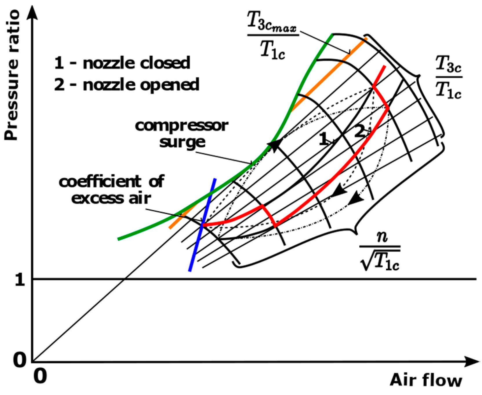
1]. Each designed control system has to keep the controlled engine within certain operational limits, as depicted in
Figure 1. These limits are defined by the maximal rotational speed and exhaust gas temperature, as well as by the surge line represented by the coefficient of excess air in the main combustion chamber. This means that the control system has to operate in a complex environment and respect the constraints of a multi-dimensional non-linear space with many uncertainties [
1].
In order to solve the aforementioned problems and deal with uncertainties in the control of turbojet engines, the methodology of robust control, as described in fundamental literature [
2,
3,
4,
5], can be applied. The reported results show that this methodology can achieve a high quality of control in a broad spectrum of operational states of complex systems. Therefore, it can be deemed a suitable candidate for application in the efficient control of turbojet engines [
6]. Based on current research in robust control of turbojet engines, the method mainly applied in turbine engine control in current publications is the
norm-based control [
7,
8].
However, application of the methodology is often done in virtual environments only [
8,
9]. The aim of the present paper is to show and demonstrate the application of this methodology in an environment with physical systems, taking into account all limitations and specifics, such as discrete forms of robust controllers, data delays, and limited action hits, all within a variable operational envelope. In a simulated environment, using
norm-based controllers as part of a turbine engine control system and the impact of those controllers on the engine’s control system stability and performance have already been studied [
7]. The aim of the study was to design a robust controller with the smallest possible output and power consumption [
7]. It was also proved that robust controllers are generally better in performance and stability than the classical control approach using proportional-integral-derivative (PID) controllers using a simulated turbojet engine [
8]. Operation in real world conditions is, however, different from such ideal calculations in a simulated continuous state space, as the measured data are often delayed and the controller operates in a discrete state space. Such uncertainties, represented by data delays or drop-outs, were modeled in a distributed aero engine control system [
9]. The paper describes an
controller designed to control the whole engine’s operating envelope, but again, the results were only obtained in a simulated environment.
The possibilities of application of robust control in turbine engines in advanced intelligent frameworks were also studied [
1]. Nonlinear behavior and uncertainty of a turbine engine with deterioration was taken and compensated by its robust control system. Using simulations with the C-MAPSS40k model, it was proven that robust controllers can effectively control a turbine engine with the mentioned types of modeled uncertainties [
10]. Data delays or dropouts in a distributed control system with impacts on uncertainty modeling as well as stability and performance of the robust control system of a turbine engine were also studied in simulated environment [
11]. Compared to predictive or classic PID controllers, robust controllers have achieved higher control quality in speed and temperature control of a gas turbine power plant [
12]. In the same study, robust controllers were tested together with the nonlinear autoregressive model, using exogenous inputs (NARX). All robust controllers were designed using the experimental NARX models and were designed using the
method. In addition, researchers from NASA Glen Centre [
13] used robust control to preserve control system properties even during engine degradation, either over time or for other reasons. They used the Lyapunov parametric depending function to design a parameter dependent control system. The robust control system was able to adapt using performance weights depending on coefficients, which were determined by the index of the engine’s degradation. Robust tracking control of turbofan engines using the
Leitmann method was applied with good results in attenuation of the engine’s uncertainties [
14]. By numerical simulations, the authors in the paper proved very good performance in stability of a turbofan engine tracking control.
The robust control approach has also successfully been applied in other engineering and aviation topics in technical practice. The classical root locus and
methods were investigated in the design of the well-known C* flight control algorithm, in order to compare advantages and disadvantages of both approaches [
15]. The root locus approach was faster and simpler to apply but gave conservative results, while the advanced
controller was better in uncertainty attenuation but more difficult to design [
15]. In another aviation application, the
theory was successfully used to fight the nonlinear behavior of autonomous aerial vehicles [
16]. A nonlinear, predictive robust controller was better in control of an autonomous plane, even with data delays, plane degradation, and instability, compared to linear controllers. The problem of vessel positioning control was also solved using
and µ synthesis, with good simulation results in frequency and time domain [
17]. An efficient combination of fuzzy control and robust control strategies were applied to design the controllers for solar collector fields [
18]. An efficient control framework for discrete nonlinear systems using a state dependent Riccati equation solution was also successfully developed using the methodology of robust control, showing very promising results on an inverted pendulum [
19].
The motivation behind the present research was to apply working approaches in robust controller design, and test them in control of a small turbojet engine in order to determine the resulting control efficiency. The aim, and the expected scientific contribution, was to research and identify the methods and approaches that will be suitable and applicable in developing digital control systems for this class of turbojet engines. This research should also answer the question of whether the design of robust controllers, which is a quite complex task, can feasibly be applied in the real-time environment of a digital control system of turbojet engines, compared to traditional control design approaches. Contrary to most simulation studies presented in the introduction, the result of this study is intended to be a pioneering practical application of robust control in a digital control system of a small turbojet engine, and it may support further developments in the control of such engines in aviation applications.
2. Modeling the iSTC-21v Engine with Uncertainties
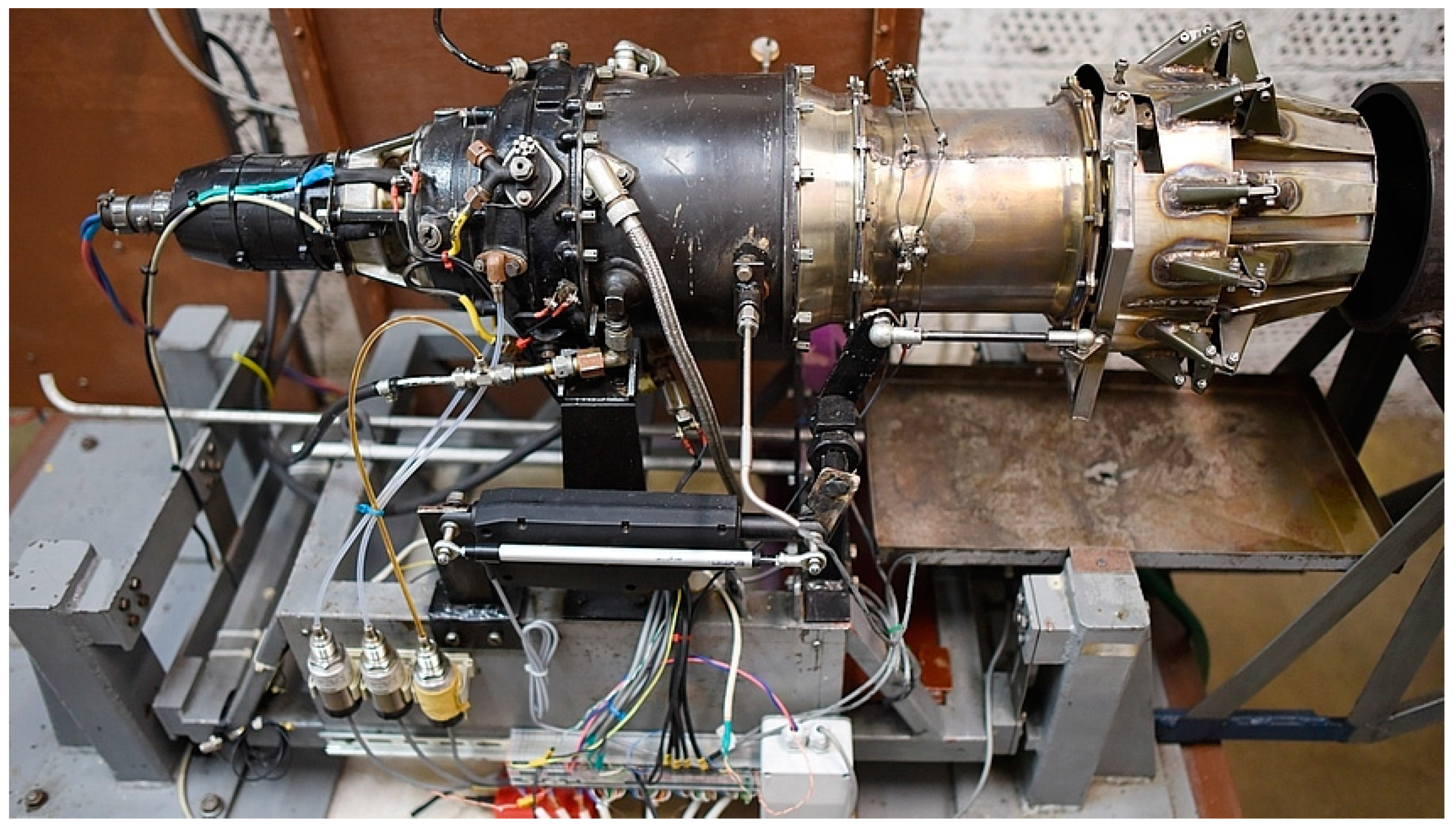
In order to design a robust control system, a model of the engine and its uncertainties must be designed. An experimental identification approach was selected to design a set of dynamic models, suitable for design of robust controllers. As a data source, a small turbojet engine iSTC-21 was employed, as shown in
Figure 2. The engine was operated in laboratory conditions with a digital data acquisition system measuring the most important input, output, state, and environmental variables, with a sampling rate set as
fs = 10 Hz. The data acquisition system, measured parameters, and the resulting data are described in detail in References [
20,
21,
22]. In the specific case of robust controller design, the nonlinearity of a turbine engine can be taken as its uncertainty. Therefore, it was necessary to design a set of linearized models of different operating points of the engine, which covered its whole operational envelope. The transfer function defining the structure of the individual linear models is defined by Equation (1). This model structure was selected according to the previous experiments described in References [
21,
22,
23]. The resulting model after Laplace transformation, which is valid for the
i-th operational point, described the dynamic dependence of the engine’s speed
n(
s) on the control variable of fuel flow -
FF(
s) (Equation (1)). The aim of the identification process was to find the coefficients
ai and
bj.
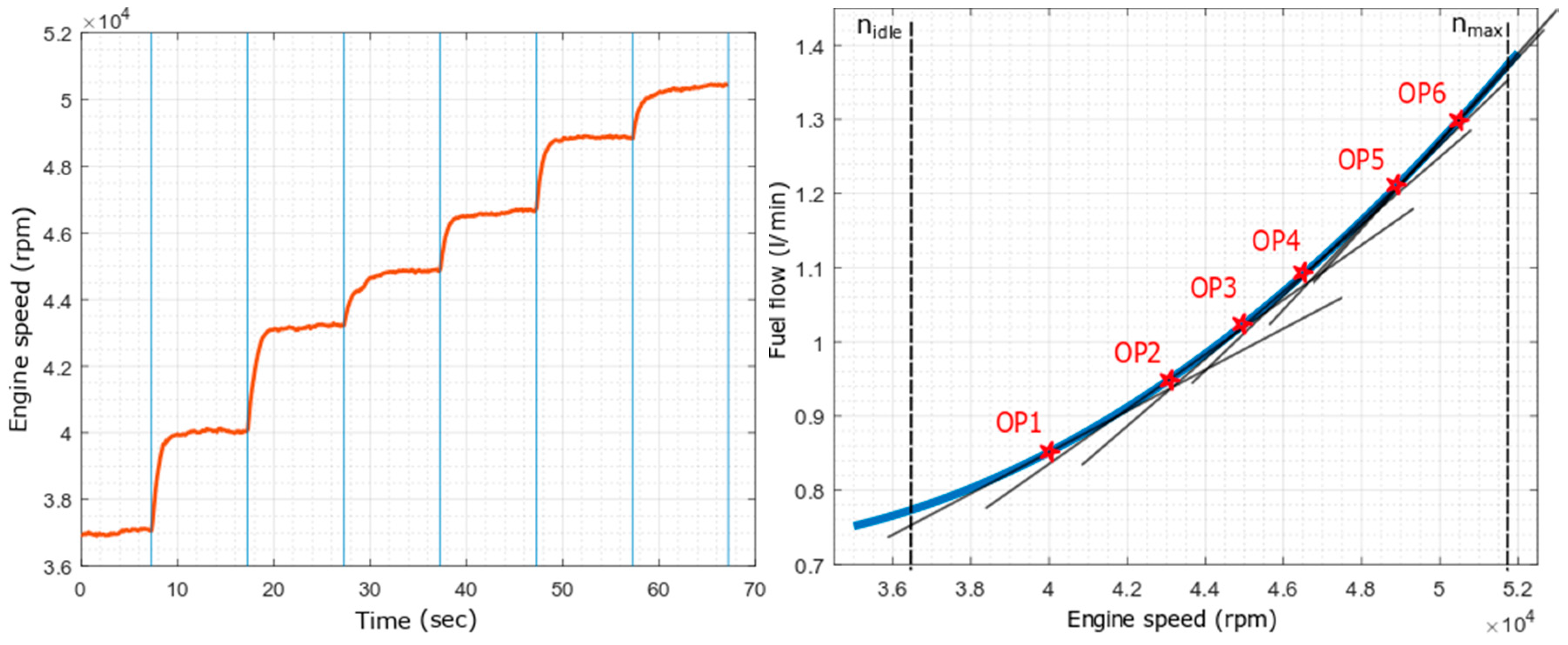
Figure 3 shows the measured dynamic engine data used for identification of linearized models for the six operational points defined as OP1… OP6, while the resulting transfer functions were designated as F
1(s) … F
6(s).
A model for each operational point was constructed; the obtained models, using an experimental identification methodology [
21,
22], are summarized and given in
Table 1. The models were evaluated using standard metrics, the mean absolute error (MAE), and the maximum absolute error (MAAE), as well as their percentage expressions (MAAPE and MAPE). The table shows that, using the methodologies presented in the previous publications [
21,
22,
23,
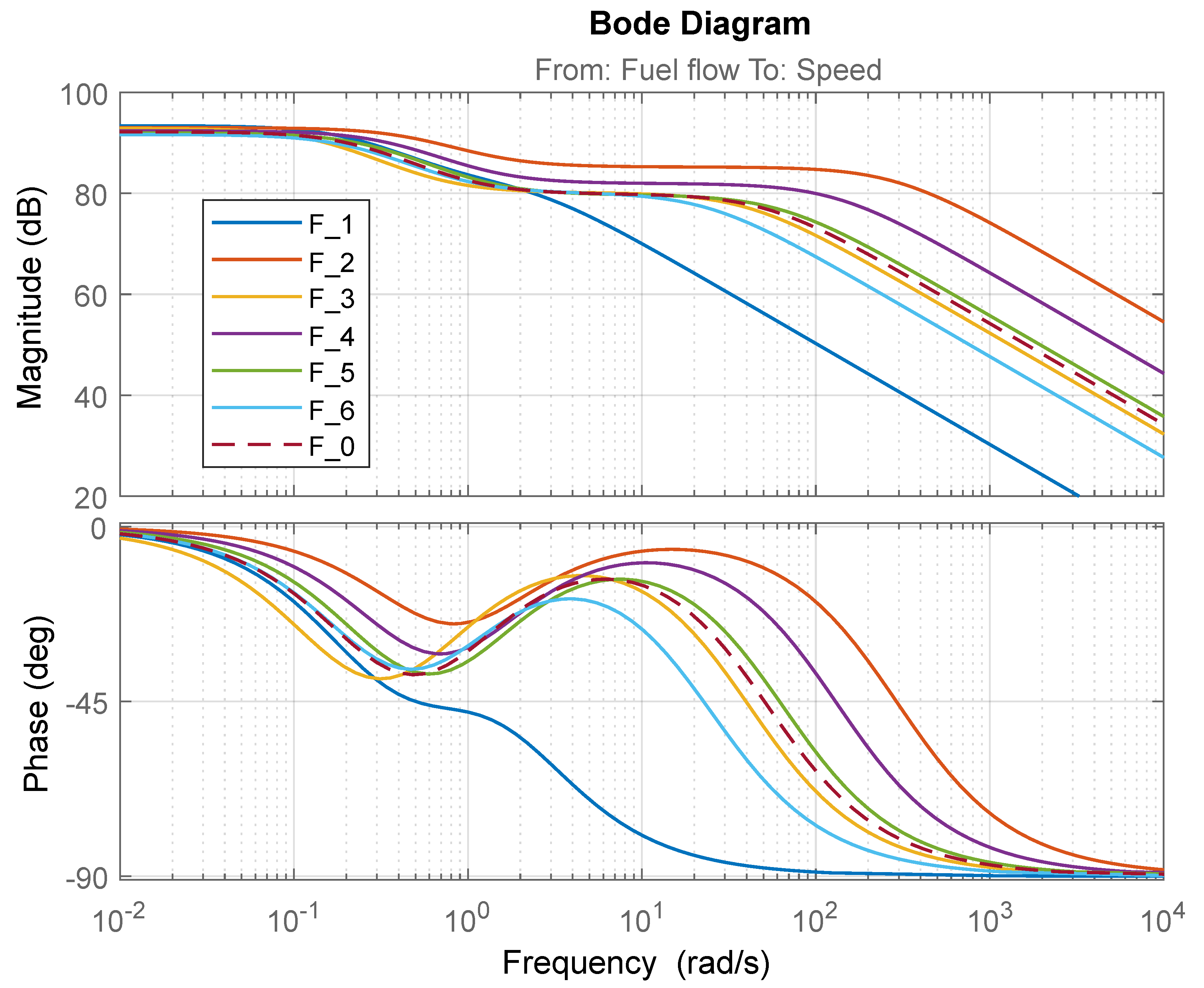
24], it was possible to achieve a precision with average errors lower than 1%. These models were used to determine the uncertainties applied in the design of robust controllers. The frequency response of the individual models is shown in
Figure 4. It can be seen that the models had a high gain, they were thus highly susceptible to changes in control inputs and noise.
The nominal engine model was computed as a mean of the individual model’s coefficients (F
1(s) … F
6(s)), with the resulting transfer function defined as follows in Equation (2) [
2,
3,
25]:
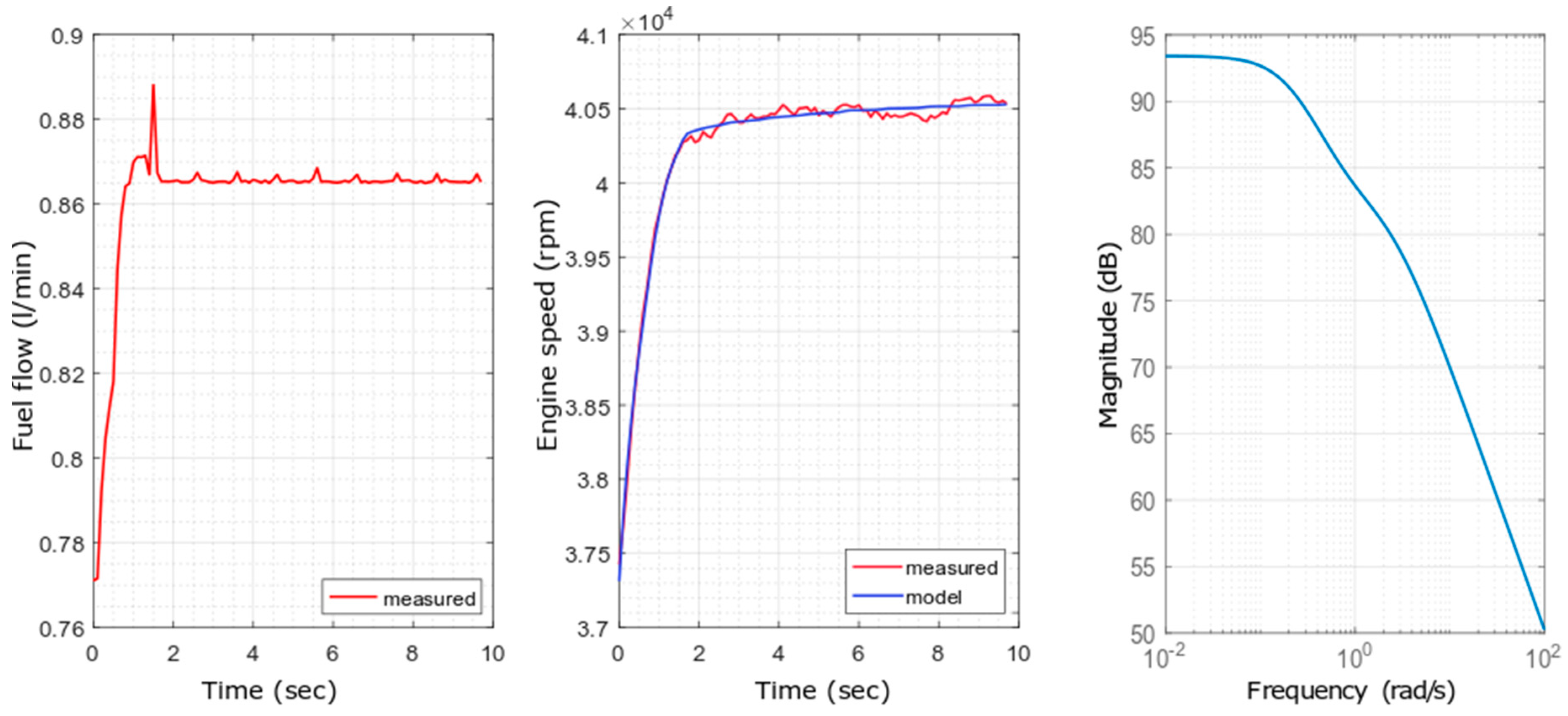
As an example of the obtained precision as demonstrated in
Table 1, the linear model for the operating point OP1 was selected and the results shown in
Figure 5. In the left part of
Figure 5, the measured fuel flow is shown (note small oscillations in fuel flow supply). The middle part shows the dynamic response of the model with the engine accelerating to a speed of 40,500 rpm, defining the operational point 1. The right part of the figure shows the model as the amplitude frequency characteristics.
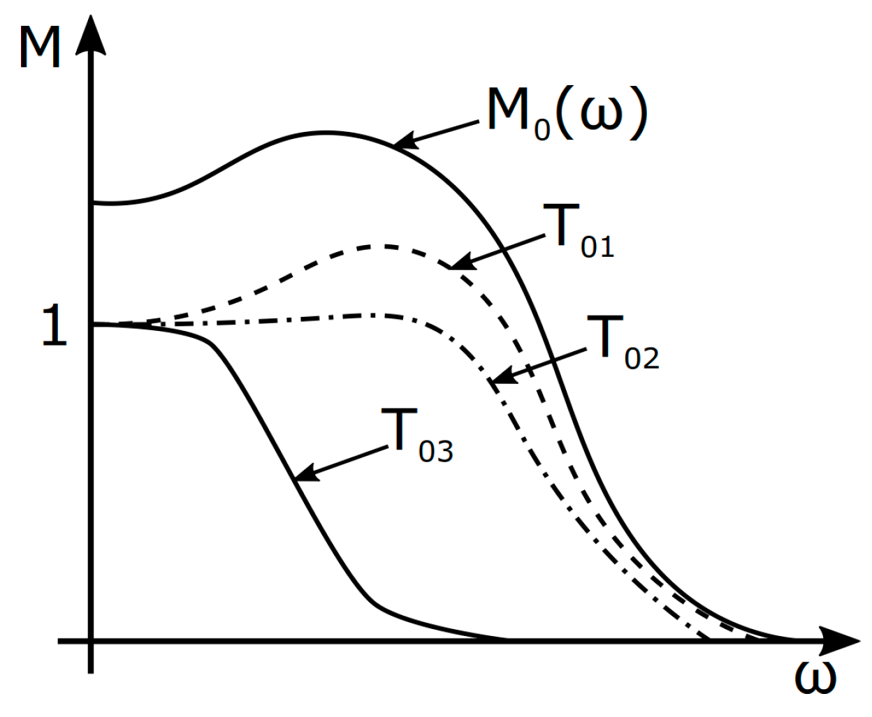
As the resulting model for a robust controller design, the nominal engine model
F0(
s) was used. On top of the model, Equation (3), showing the additive dynamic uncertainty, and Equation (4), presenting the multiplicative dynamic uncertainty were used in our investigation into the design of robust controllers [
2,
3,
4].
where
F0 (s) represents the nominal model of the dynamic system, in this case a small turbojet engine described in Equation (2).
wa(s) represents the transfer function of the additive uncertainty.
wm(s) represents the transfer function of the multiplicative form of uncertainty.
δ(s) represents the absolute value of the uncertainty in the interval: <−1,1>.
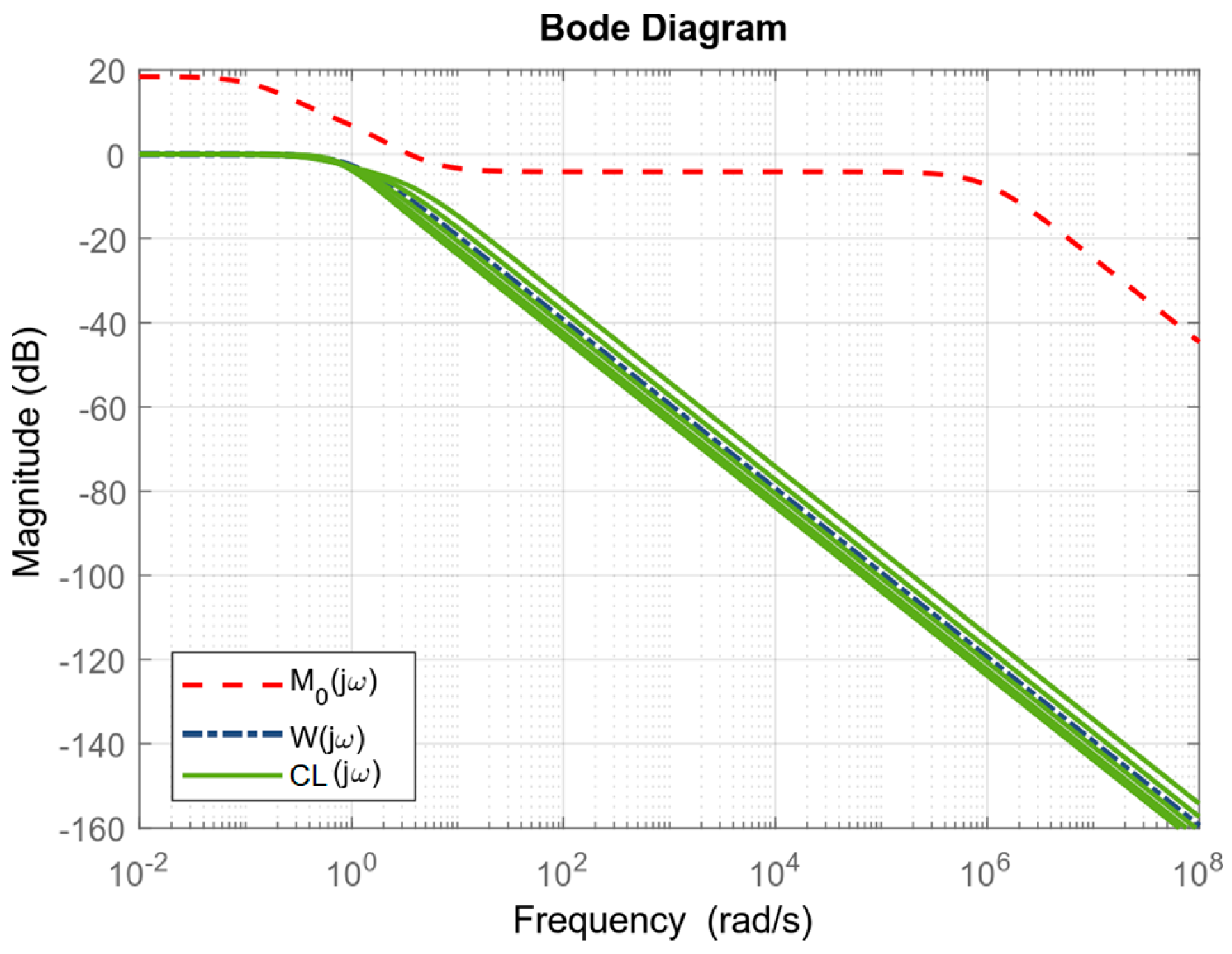
For the small turbojet engine iSTC-21v, the following transfer functions of the uncertainties, using the models F
1(s) … F
6(s), were obtained:
Having computed the nominal model of the engine F0(s), and computed its uncertainties using linearized models across six operational points, the robust controllers could be designed. After preliminary tests and initial design of controllers, the additive uncertainty as modeled in Equation (5) was selected and applied in the following sections.
4. Simulation and Experimental Results
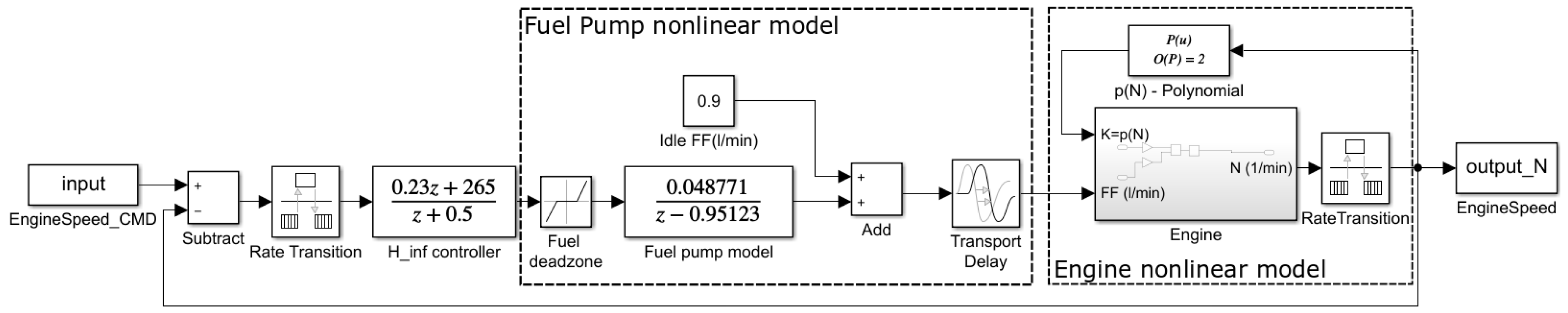
Simulations and implementation of the calculated controllers were realized using a closed loop feedback speed control scheme, as shown below in
Figure 8. The controllers were discretized using a sampling period set as
Ts = 0.01 sec.
Evaluation of the calculated robust controllers in simulation environment was realized using a nonlinear model of the iSTC-21v [
21,
22]. This model is able to describe both the multi-mode operating envelope and some delays, which are caused by the engine’s systems as well its own dynamics. In laboratory conditions these are the most significant uncertainties, because all other ambient/environmental conditions are relatively stable. The simulation results show that the H-infinity controller designed using the loop shaping methodology approach accelerated the engine through step changes in the operational speed set-points, up to its theoretical maximum speed limit. These simulation results showed that the controller was stable and could be tested on a real small turbojet engine on a test bench. The best performing robust controllers were the small gain robust controller (SG) and the
robust controller. These two controllers were compared to a classical PI controller designed using the optimal module methodology [
20]. The experiment in a simulated environment, as presented in
Figure 9, showed that all three controllers were very smooth in operation and were able to control the engine with sufficient control quality. The next step was to use the best performing controllers and test them on a real object—the small turbojet engine iSTC-21v—by updating its control system.
Figure 10 illustrates the response of the individual controllers in a laboratory test, using the iSTC-21v engine running on a test bench with a real-time data acquisition control system, with the tested controller implemented in a situational control system [
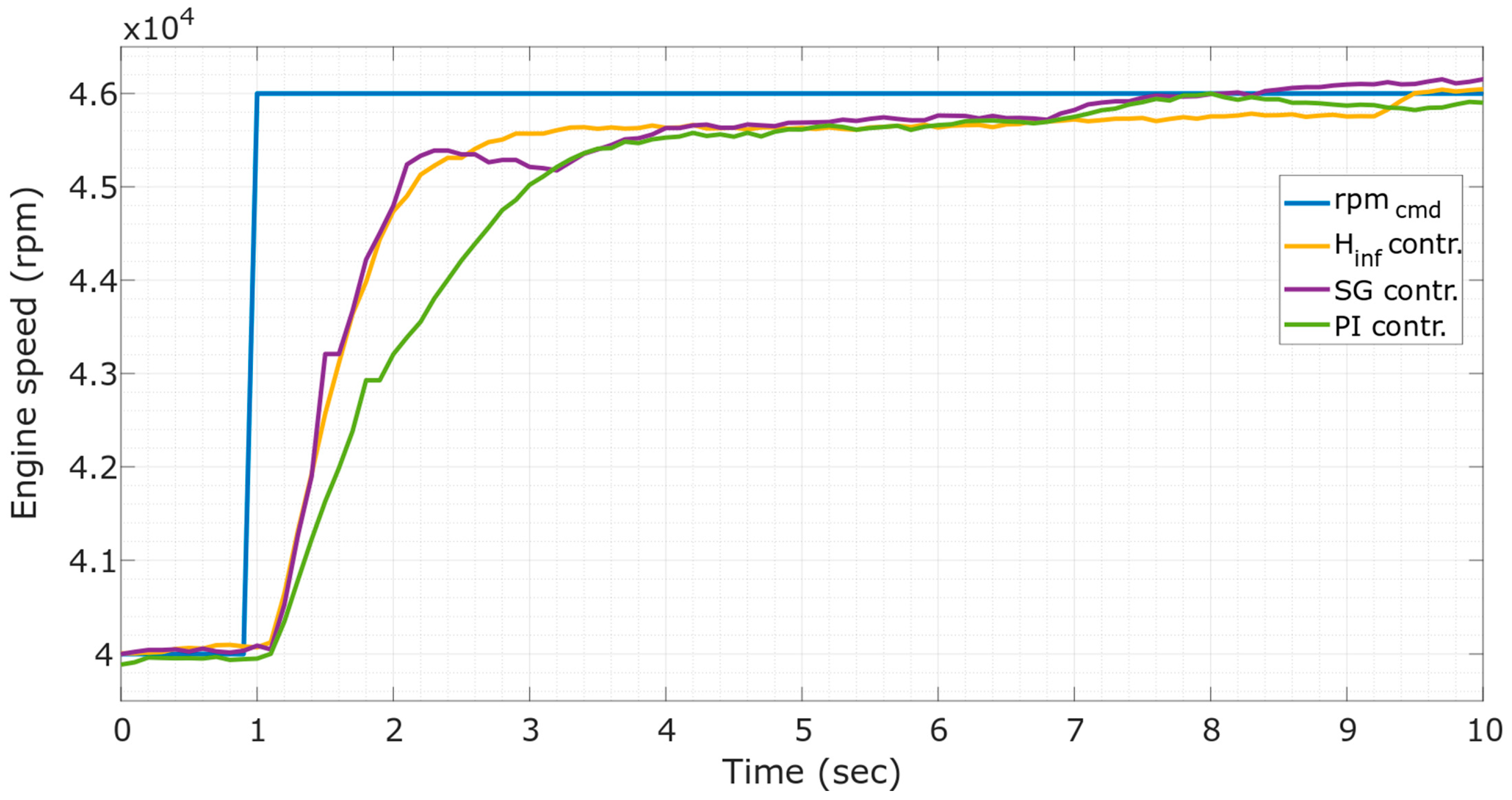
20] without switching, and using only a single controller throughout the whole operating range of the engine. The first set of test results, presented in
Figure 9, shows the controllers responding to a step change in the set-point control signal, accelerating the engine from the operating point of
N_idle = 40,000 rpm to the operating point defined by the command signal
N_command = 46,000 rpm. The command signal is shown as a blue line in
Figure 9, and the responses of the individual controllers designed by the small gain method, the
method, and an optimal PI controller are also shown. All controllers performed in an acceptable manner, robust controllers having faster acceleration at the physical limits of the fuel pump and the engine itself.
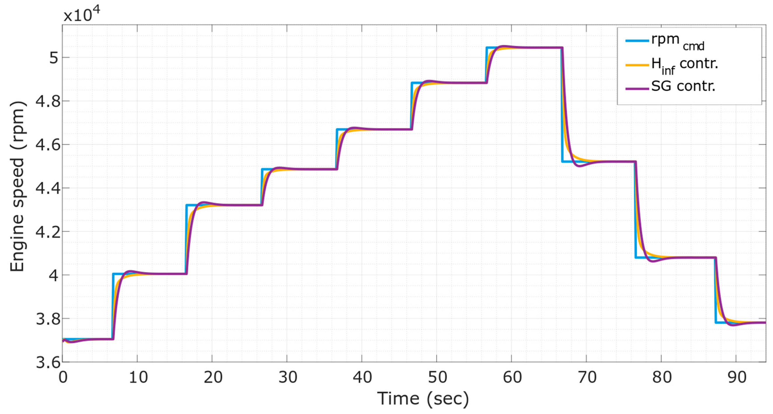
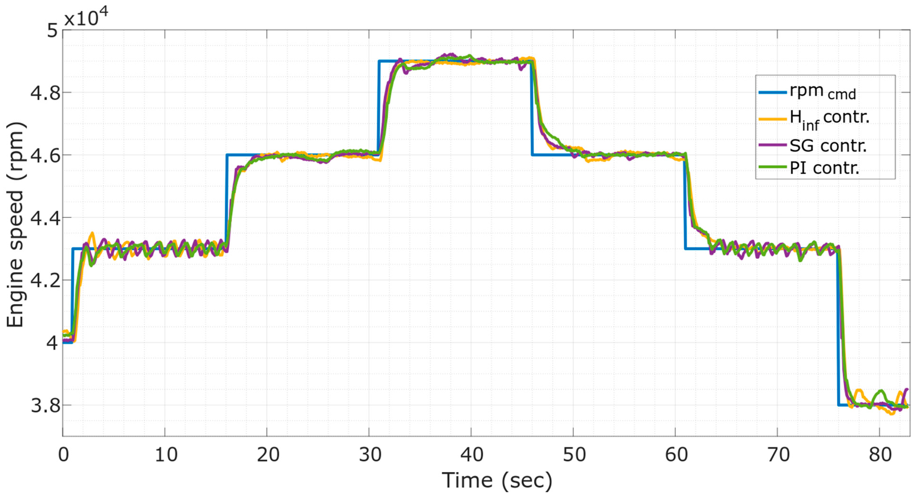
The other test, which illustrated the performance of the designed controllers showed step accelerations of the engine nearly up to the maximal speed of the engine N_command = 49,000 rpm. As can be seen in the results, all controllers exhibited slightly oscillatory behavior around certain operational points, namely the idle operational point, defined at N_command = 38,000 rpm, and the operational point N_command = 43,000 rpm.
The oscillations are believed to have been caused by high susceptibility of the controlled system to very small changes in fuel flow supply from the fuel pump, as shown in the Bode diagrams in
Section 2. They could also be attributed to the age of the engine and ageing effects on its fuel system and nozzle construction. To get rid of these effects in the iSTC-21v engine, it would be necessary to replace the fuel nozzles and improve the fuel supply system. These oscillations could be attenuated by the controllers by increasing the response times of the controller, however, this would go against the design aim to have the engine accelerated as fast as possible. Another solution to this problem would be the application of a situational control system with switched controllers, where this oscillatory behavior was eliminated using specifically designed controllers for stable conditions with higher robustness, albeit slower response [
20]. The obtained controllers are given in a discrete form in
Table 2.
The experiments showed that robust controllers have a slight advantage over the classical optimal PI controller in performance. The performance of the individual controllers is shown in
Table 3. Acceleration characteristics were defined according to the criteria of settling time, defining the time it took for the speed to reach 90% of the commanded speed, and maximal overshoot of the controller averaged across six operational points as shown in
Figure 11. In the steady state where the speed was stable, mean average error across six operational points, shown in
Figure 11, was evaluated. We can see that the lowest settling time and the best transitional behavior (during acceleration) is obtained by using the
controller. In steady state the robust
was slightly better in mean absolute error than the small gain robust controller. The PI controller designed by the optimal module design method had the worst performance, although it was still acceptable for application in a small turbojet engine.
5. Conclusions and Discussion
The results, obtained in simulation and laboratory experiments, show that a robust control approach can be applied to control the speed of a small iSTC-21v turbojet engine. This means that the theory of robust control can be successfully applied to a real turbojet engine using a digital control system. A suitable approach to design of robust controllers has been found, which can be further built on and applied in this class of small turbojet engines. The recommended dynamic model for use in design of robust controllers for small turbojet engines is a second order nominal model, computed as an average across several operational points covering the operational envelope and expanded by additive uncertainties.
The dynamic engine models presented in the paper are suitable for design of robust controllers for small turbojet engines with static thrust from 50 up to 100 kilograms. The developed nominal model can be used in design of a robust controller; the best performing method in laboratory conditions and using a digital control system was the H-infinity method, using the loop shaping approach in its design as described in section three. The robust controllers, which are deemed to be suitable for the class of small turbojet engines, are given in
Table 2. It needs to be noted here that all designed robust controllers performed flawlessly in simulated environment, however when implemented on a real engine in laboratory experiments that was not always case, as the controllers oscillated at certain operational points. This illustrates the fact that good simulated performance of a robust controller does not guarantee similar performance in a physical system. Transition times during acceleration were improved by about 0.5 seconds using robust controllers, the maximal overshoot was decreased, and other comparative criteria were also improved as shown in
Table 3.
In conclusion, it can be said that the improvement using robust controllers on a real turbojet engine is rather marginal when dealing with an engine at the ground level. Higher uncertainty would be present when using the engine in flight conditions, where the outer environment has a significant impact on its thermodynamic performance. It can be hypothesized that robust controllers would significantly improve performance of the engine in these conditions, however, the designed uncertainties would have to be recalculated. Performance could be further enhanced by application of algorithms from the area of computational intelligence, as illustrated in some recent works [
27,
28]. Another path would be to test the possible application of additive and multiplicative uncertainties to improve results [
29]. More complex tests resembling certain flight conditions can be done using the variable exhaust nozzle of the iSTC-21v engine in future experiments.

 ,
, 


