Article

Design and Prototyping of Miniaturized Straight Bevel Gears for Biomedical Applications

by
Antonio Acinapura
1,*,
Gionata Fragomeni
2,
Pasquale Francesco Greco
3,
Domenico Mundo
1,
Giuseppe Carbone
1 and
Guido Danieli
3
1
DIMEG, University of Calabria, 87036 Rende (CS), Italy
2
Magna Graecia University of Catanzaro, 88100 Germaneto (CZ), Italy
3
Calabrian High Tech—CHT S.r.l., 87036 Rende (CS), Italy
*
Author to whom correspondence should be addressed.
Machines 2019, 7(2), 38; https://doi.org/10.3390/machines7020038
Submission received: 8 May 2019 / Revised: 29 May 2019 / Accepted: 31 May 2019 / Published: 4 June 2019
(This article belongs to the Special Issue Advances of Italian Machine Design)

Abstract

:
This paper presents a semi-automated design algorithm for computing straight bevel gear involute profiles. The proposed formulation is based on the Tredgold approximation method. It allows the design of a pair of bevel gears with any desired number of teeth and relative axes inclination angles by implementing additive manufacturing technology. A specific case study is discussed to calculate the profiles of two straight bevel gears of a biomedical application. Namely, this paper illustrates the design of the bevel gears for a new laparoscopic robotic system, EasyLap, under development with a grant from POR Calabria 2014–2020 Fesr-Fse. A meshing analysis is carried out to identify potential design errors. Moreover, finite element-based tooth contact analysis is fulfilled for determining the vibrational performances of the conjugate tooth profiles throughout a whole meshing cycle. Simulation results and a built prototype are reported to show the engineering feasibility and effectiveness of the proposed design approach.

1. Introduction

Over the last decades, robotic systems have improved the performance in terms of time-consuming and quality of many biomedical applications. In particular, endoscopic surgical operations requiring accurate movements and minimal invasion may get significant advantages from robotic assistance. Laparoscopy was firstly promoted as a diagnostic modality [1,2] and later it was used for operations in the fields of gynecology, urology, and cardiac surgery [3,4,5]. AESOP, the automated endoscope system for optimal positioning, represented the first solution eliminating the need for one additional person at the operating table. It is a computer-controlled robot positioner that holds the laparoscope and is moved by means of surgeon’s foot and hand controllers [6]. Another kind of computer-assisted system has been developed to give assistance in endoscopic coronary artery surgical procedures. The so-called ZEUS system is a 5-degrees of freedom (DOF) voice-controlled robotic surgical system [7], which allows duplicating the DOFs of a standard endoscopic instrument controlled by the hand of a surgeon. Additionally, the da Vinci robotic surgical system adopts the principle of a master–slave manipulator, in which the handle of the instrument and its top part are physically divided [8]. Although da Vinci and ZEUS provided certain advantages like high visual magnification, movement scaling, tremor filtering, and dexterity, some drawbacks must be underlined, such as interference among the robotic arms, excessive encumbrances, and lack of tactile feedback. These drawbacks motivated the exploration of other design solutions such as the EasyLap robotic system [9], which uses instrumentation already available in hospitals.
The aim of this work is to improve the performances of the EasyLap robotic system for laparoscopic surgery operations [9]. It is made of four to five arms, which are fixed on a common base frame, each being passively self-balanced with five DOFs, while the sixth is supplied by the instrument in use turning about its axis. Four arms are usually actuated, while one is dedicated to the optics and is automatically moved, pointing to the region in which the instruments are manipulated by the doctor. The attention is focused on the design of the adaptor that handles the movements of the traditional surgical instrument that must turn along its axis to modify the plane of opening of the forceps, which needs a particular attention being the most significant part, especially for endoscopic surgery operations.
One of the key features of the EasyLap robotic system is the possibility to fully detach the sterile component (holding the forceps) from the non-sterile part (containing the motors, force sensor, and electronics). For this purpose, it is necessary to keep the motors parallel and, at same time, it is necessary to provide a low-cost transmission solution for the rotation of the end-effector with specific small relative axes inclination angles and reducing ratios of approximately 0.5. A careful search found that there is no off-the-shelf solution being able to satisfy both required transmission and geometric constraints. Accordingly, there has arisen a need to design a customized bevel gear solution, which can satisfy all the design constraints such as inclination/transmission angles with a low-cost and compact solution. Additionally, standard gear design solutions fail to provide a customized design with the desired design characteristics and performance, especially for reducing the encumbrance and, at the same time, ensure good vibrational behavior of the end-effector.
The traditional manufacturing processes are mainly cutting methods that strictly influence the tooth profile of a gear and, thus, its performance. Face milling and face hobbing are two of the main generating methods. However, they do not guarantee customizable control of the tooth profile and good vibrational performances when applying small loads [10]. Accordingly, a specific design methodology is herewith proposed. This design methodology is based on an extension of the Tredgold approximation method [11]. It is intended for miniaturized straight bevel gears with any desired number of teeth and relative axes inclination angles.
The proposed design method assumes the use of an additive manufacturing technology that was not considered in conventional design methods such as those proposed in literature [12,13]. The proposed method implements a semi-automated pre-processing tool to generate a point-based description of the tooth flank surfaces and then to create a desired finite element (FE) model of the gear pair. The FE model has been used to compute a tooth contact analysis (TCA) of the mating gears in order to determine their vibrational performances, which are extremely significant for the considered biomedical application. The TCA is performed by means of nonlinear FE simulations in the NX Nastran (SOL 601) environment. Simulation results are discussed to attest to the engineering feasibility and effectiveness of the proposed design approach. A 3D-printed prototype of the designed mating elements has been manufactured and mounted on the end-effector of the EasyLap.

2. Tredgold-Based Tooth Profile Generation

Bevel gears are used when the motion has to be transmitted between intersecting shaft axes. In this work, straight bevel gears with involute tooth profiles were considered in order to actuate the end-effector of the robotic system EasyLap when used for laparoscopic surgery operations. Since encumbrances must be minimized, it is necessary to perform a careful design of the mating gears. Small gears and small shaft angle represent the main topics of the proposed gear design.
Traditionally, bevel gears are manufactured by using cutting methods such as gear hobbing, bevel gear generators, or CNC milling. These methods start from a bulk workpiece and remove material to generate a correctly profiled tooth form [14,15,16]. These manufacturing processes do not allow for an easy customization and miniaturization. Other manufacturing methods can be based on die casting or injection molding [17]. These methods are suitable only for large production lots, since they require an expensive mold design and production. New production processes such as 3D printing have been changing the time-to-market of industrial products but also the design process. In this work, the use of 3D printing techniques is taken into account for modifying the generating method that is used to design a desired straight bevel gear pair. This method can be very fast and cost effective for small production lots of small size plastic gears, such as those considered for the EasyLap robotic system. However, it is necessary to fully design the bevel gear mating profiles in terms of a cloud of points to be provided as input of a 3D printer. Accordingly, this paper proposes a specific semi-automated design algorithm for computing straight bevel gear involute profiles.
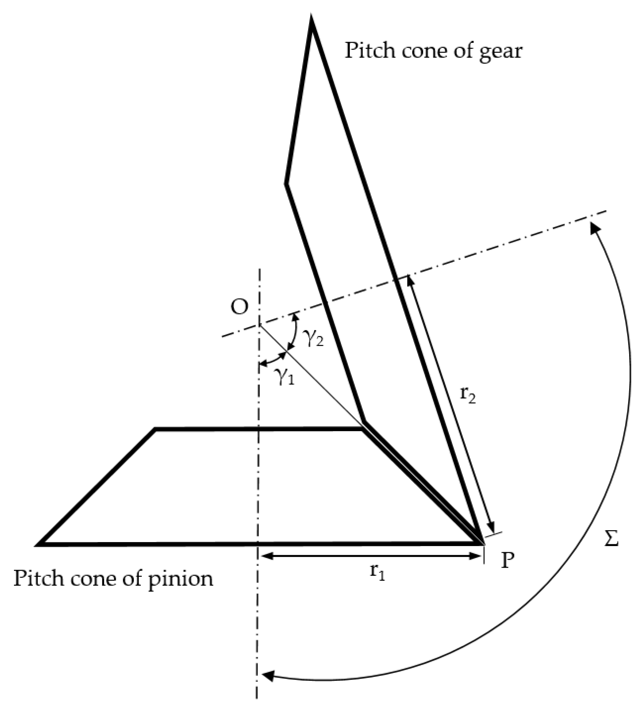
The Tredgold approximation method [11] is usually adopted to study bevel gears, reducing the problem to that of ordinary spur gears. In the proposed approach, the aim is not only to study bevel gear problems but also to design the bevel gear pair starting from its equivalent spur one. As seen in Figure 1, r1, and r2 are the pitch radii, respectively, for the pinion and the gear. The angles γ1 and γ2 are defined as pitch angles and their sum is equal to the shaft angle Σ.
The gear ratio is defined in the same manner as for spur gears:
τ = ω 1 ω 2 = r 2 r 1 = z 2 z 1 ,
where ω and z are, respectively, angular speed and number of teeth of the considered gear. Since the distance OP can be written as
O P = r 1 sin γ 1 = r 2 sin γ 2 ,
then combining them gives
sin γ 1 = r 1 r 2 sin γ 2 = r 1 r 2 sin ( Σ γ 1 ) = r 1 r 2 ( sin Σ cos γ 1 sin γ 1 cos Σ ) .
Rearranging Equation (3) gives
{ tan γ 1 = sin Σ r 2 r 1 + cos Σ = sin Σ z 1 z 2 + cos Σ tan γ 2 = sin Σ r 1 r 2 + cos Σ = sin Σ z 2 z 1 + cos Σ .
The pitch radius ri for the i-th gear is defined as
r i ( w ) = m ( w ) z i 2 ,
where m(w) is the module. Considering the bevel gears, m varies as a function of the face width of the considered gear. Focusing the attention on Equations (4) and (5), once the shaft angle, the number of teeth, and the function of the module are fixed, it is possible to obtain the pitch cones of the gear pair elements.
The Tredgold approximation method allows starting from the pitch back-cone representation of a bevel gear pair in order to build an equivalent problem of spur gears. As long as the gear is made up of eight or more teeth, the method is accurate enough for practical purposes [12]. According to the Tredgold method, an equivalent spur gear is built whose pitch radius re is equal to the back-cone radius, such as the radius of the cone whose elements are perpendicular to those of the pitch cone at the largest end of the teeth. Once the equivalent spur gears are obtained, the tooth profiles can then be defined. The results obtained by tooth contact analysis of the equivalent gears correspond closely to those of the bevel gears.
The geometrical relations that occur between the bevel and spur gears are
r e q , i ( w ) = r i ( w ) cos γ i ,
z e q , i ( w ) = 2   π   r e q , i ( w ) p ( w ) = z i ( w ) cos γ i ,
where req,i and zeq,i are, respectively, the pitch radius and the number of teeth, usually a non-integer, of the i-th equivalent spur gear; p is the circular pitch of the bevel gear measured at the width w of the gear. In order to make the following discussion easier to understand, the procedure will be shown for a single gear pair element and for a fixed value of the module m, which would be repeated for a discrete number n of intermediate values between mbc (module at the back cone) and mfc (module at the front cone).
Once the geometrical parameters of the equivalent gears are obtained, it is possible to focus the attention on the 2D design of the involute profiles using the following Cartesian equations:
{ x e q = r b , e q ( sin θ θ cos θ ) y e q = r b , e q ( cos θ + θ sin θ ) ,
where rb,eq is the radius of the fundamental circle of the equivalent gear and θ is the involute angle that varies between zero and θ t .
θ t = ( r t , e q r b , e q ) 2 1 ,
where θ t is the angle at which the involute reaches the addendum circle and r t , e q is its radius. It is usually useful to adopt the polar coordinates ( ρ , ϕ ) where
{ ρ = ( x e q 2 + y e q 2 ) ϕ = atan ( x e q y e q )      .
A significant value that will be useful for 3D parameterization is ϕ p , which is the value of ϕ at θ p , where the involute meets the pitch line. The 3D parameterization of the single tooth of the bevel gears is shown in Equation (11):
{ x = R sin ( δ cos γ ) cos γ       y = R cos ( δ cos γ ) cos γ       z = r v a g + r e q tan γ R sin γ ,
where R and δ are the polar coordinates, while r v a g is the radius of the virtual auxiliary gear. The latter should mesh with the equivalent spur gear, but it is only used to define the z-coordinate of the gear flank parameterization. They can be defined as reported in Equations (12)–(14).
R = { r f , e q = r e q 1.25   m                 r o o t   p a r t ρ                        a c t i v e   f l a n k   p a r t r t , e q = r e q +   m                     t o p   p a r t ,
δ : { π z e q δ π 2   z e q ( ϕ p ϕ )                      l e f t   r o o t   p a r t π 2   z e q ( ϕ p ϕ ) < δ ( ϕ p ϕ )        l e f t   a c t i v e   f l a n k   p a r t ( ϕ p ϕ ) δ ( ϕ p ϕ )                         t o p   f l a n k   p a r t ( ϕ p ϕ ) δ < ( ϕ p ϕ ) + π 2   z e q          r i g h t   a c t i v e   f l a n k   p a r t π 2   z e q + ( ϕ p ϕ ) δ π z e q                       r i g h t   r o o t   p a r t ,
r v a g = r e q sin γ .

3. The Proposed Semi-Automated Design Method

The proposed semi-automated process to generate the design of straight bevel gears and the contact performance of the prescribed gear pair can be divided into three main phases, as described in Figure 2.
The Tredgold profile generation phase is based on Equations (1)–(14) as outlined in the previous section. The flow-chart in Figure 3 provides a detailed description of the calculation process that can be iterated in order to compute the straight bevel gear tooth profiles with desired performance. The idea is that, having fixed the relative incidence angle between the axes Σ of the gears, the relative number of teeth z1 and z2, the module m, and the pitch angles γ1 and γ2 can be consequently obtained. Each gear can be treated with the Tredgold method in an iterative manner by considering a certain number of discrete values for the module along the width of the considered gear. It is also possible, for each gear pair element, to obtain a second gear having an orthogonal axis and ensuring conjugate motion. We define them as virtual auxiliary gears. They can have a non-integer number of teeth and cannot be built. However, the gears we are designing will have the same module, and the involutes meshing in a cone perpendicular to their pitch cone do surely mesh.
Table 1 reports an example of gear data for a computed bevel gear pair in order to analyze the contact characteristics of a straight bevel gear pair. Data have been computed with the proposed Tredgold profile generation algorithm by considering a shaft angle of 12°. Hence, the flank data is generated as an ordered set of points, defined by Cartesian coordinates. The cloud-of-points representation is stored in an Excel file and then given as input to a pre-processing Matlab tool that automatically creates the FE mesh of each gear pair element in the gear mesher phase.
The creation of the finite element mesh is customizable by the user. The latter can change the dimension and the number of elements and provide accuracy of the analysis. Biquadratic interpolation techniques, presented in [18], are used in order to accurately build the tooth surfaces starting from a certain number of Cartesian points. Depicted in Figure 4 is an example of the FE mesh creation for the input gear.
Once the FE mesh is available, the third part of the semi-automated design process consists of numerical tooth contact analysis computation, following the steps below:
  • Creation of the FE assembled model.
  • Definition of the initial gear pair kinematic configuration.
  • Specification of loading campaign and boundary conditions.
  • Multiple static nonlinear simulation.
  • Post-processing of the tooth contact analysis results.

4. Tooth Contact Analysis

The tooth contact analysis consists of a computerized and numerical procedure that allows identification of the main performance of two mating gears in terms of static transmission error (STE) and distribution of contact pressures along the gear flanks. Since the quality of the motion transmission is strictly dependent on the gear profiles and mainly on the interaction of the mating elements of the gear pair, the TCA plays a key-role in the gear design. Many phenomena occur when two mating gears come into contact. Contact conditions can vary depending on arising misalignments, assembly errors, or micro-modifications. The variability of the contact mechanics leads to nonlinear problems, whose analytical solutions are too difficult to be suitable. Hence, over the last decades of the twentieth century, TCA has been commonly extended with finite element analysis (FEA) [13] or with analytical multibody approaches [10].
In this work, an unloaded tooth contact analysis (UTCA) is computed in order to consider pure geometric conditions for contact detection. On the other hand, results of a loaded tooth contact analysis (LTCA) are presented to provide a more realistic description of the gear pair contact behavior. The load’s application leads to tooth bending deflections. It modifies the overall contact conditions and specifically the contact ratio that is given as the number of teeth, which are instantaneously in contact. If the contact ratio varies, the load sharing and the meshing stiffness vary and, consequently, a vibrational excitation is introduced, as outlined in [19,20,21].

4.1. FE-Based Tooth Contact Analysis

Due to the occurring nonlinearities, nonlinear FE-based contact simulations have been conducted by means of a commercial software package. The FE model of the gear pair is created using a dedicated preprocessing software tool that allows the creation of discretization of the desired gear flank geometry starting from a cloud-of-points based representation of the three-dimensional gear flanks and the gear blank data. The in-house code of the preprocessing tool allows the user to fully handle the size and the density of the mesh, avoiding problems of convergence and stability of the solutions.

4.1.1. FE Model Creation

The aim of the FE-based tooth contact analysis is to perform the static nonlinear solution in order to investigate the contact zone of the mating gears inside a whole cycle of meshing. Therefore, a FE-based approach requires:
  • Development of the finite element mesh of the gear drives.
  • Definition of contacting surfaces.
  • Establishment of boundary conditions in terms of load and constraints.
  • Post-processing of the results.
The FE model of the straight bevel gear pair is obtained by discretizing the gear geometry as a connected set of 3D elements. In this work, six-sided solid elements (HEXA8) have been chosen. Since static nonlinear simulations have significant computational times, the FE model of each gear is characterized by a combination of three FE mesh sections, each with its own mesh density:
  • The finer part includes the teeth most likely to enter in contact as the load increases.
  • The very coarsely meshed section holds most of the gear that will not be in contact during the contact simulations. It is necessary only to correctly approximate the overall blank stiffness without introducing additional and unneeded degrees of freedom to the model.
  • The third part is made up of two small intermediate sections (each on every side) to connect the fine and the coarse mesh parts. Its main task is avoiding discontinuities between the fine and the coarse parts, which could provide bad results or convergence problems for the simulations.
Figure 5 shows the final FE model of the analyzed gear pair.
For the finer part, the number of elements that characterizes the active flanks of the gears is equal to the number of elements of the cloud-of-points representation given as input in the preprocessing phase. This choice has been adopted in order to use the proper input data, while avoiding errors of interpolation techniques during the preprocessing phase.
As it can be seen in Figure 5, 2D rigid body elements (RBE2) were used at the inner part of each gear in order to force the same boundary conditions, defined at the single central node, to all the nodes that lies on the inner cones of the gear pair elements. During the simulation, the gear was kept fully constrained, while the pinion was allowed to rotate about its rotational axis.
The external torque was applied on the pinion’s rotational axis. In this work, TCA was performed for five different load cases: 0.01 Nm, 0.1 Nm, 0.5 Nm, and 1 Nm. The studied load cases were chosen considering a maximum load of 0.02 Nm as constrained by the expected operating conditions. The 0.01 Nm load case was defined as the “unloaded case”. This was the load that allowed consideration of the pure geometric condition, with no bending tooth deflections, in the mating gears contact analysis. The aim of this work was to propose a suitable design approach for straight bevel gears. The methodology can be used to generate straight bevel gear pairs with any material. In a preliminary prototyping phase, the 3D printed gears represented a proof of the design methodology concept. Moreover, future developments aim at adopting metal powders and sintered element gears. For this reason, the simulations were computed by setting the properties of steel, which is the standard material for geared transmissions. The chosen steel material provided the values of E = 200 GPa (Young modulus) and ν = 0.3 (Poisson ratio) that were assigned to both pinion and gear.

4.1.2. Kinematic Configuration

Each geared body has to be analyzed in its own kinematic configuration in order to obtain high power transmission performance. Conjugate motion consists of perfect motion transfer that can be maintained for every considered roll angle during a complete meshing cycle. The latter is defined as
ϕ m c = 2   π z ,
where ϕ m c is expressed in radians and z is the number of teeth of the considered gear. In this work, the results refer to the pinion’s meshing cycle that is equal to about 0.449 rad. However, toothed bodies have to transmit a certain load during the engagement. Since they are not characterized by infinite stiffness, their profile elastically deforms, giving rise to an unsteady component in the relative angular motion of the mating gears. This component is due to the periodic variation in the stiffness of the gear mesh that can be mainly ascribed to the fluctuation of the contact ratio. The latter is the instantaneous number of teeth in contact during the rotation. Since the meshing stiffness varies, no perfect motion can be transmitted and the mating teeth can no longer be considered conjugate. The condition of non-conjugacy is one of the main sources of dynamic excitation that a gear design tries to minimize at operating conditions.
The static transmission error is an index of the excitation that occurs on the geared systems and of their performances. It considers the difference in rotation between the actual position of the output gear and the position that the gear would occupy in the case of perfect drive.
S T E = ϕ 2 z 1 z 2 ϕ 1 = ϕ 2 τ ϕ 1 ,
where ϕ 1 and ϕ 2 represent the rotational angles of the pinion and the driven gear around the correspondent axis of rotation, respectively; z 1 and z 2 are the numbers of teeth and τ is the transmission ratio.
In the presence of pure kinematic motion, the STE should be ideally equal to zero. Equation (16) allows the expression of the STE in μrad as a relative rotation, but it might be usually converted into relative displacement μm by using the pitch radius of the considered gear.
Regarding the starting configuration of the static simulations, the gear pair was oriented in such a way that the mating flanks were in close contact. This operation was not manually done, because the required initial rotational angle of the input gear was determined considering the mean value of the unloaded transmission error (UTE), which is equal to 0.001679 rad. It represents an offset value, since the mean value of STE related to a conjugate gear pair should be null.

4.1.3. Contact Detection Strategy

In order to analyze the contact behavior of the considered gear pair, it was useful to adopt the finite element analysis (FEA). The used contact detection strategy takes place from an FE discretization of the contact interfaces. In this work, the so-called node-to-surface approach was used, which is based on the definition of two kind of contact surfaces: the slave and the master surfaces. According to the considered method, the nodes on the slave surface cannot penetrate the segments of the master surface. The selection of these regions is relevant and results from several considerations about mesh size, surface curvatures, and material. Here, the pinion was chosen to be the slave, while the driven gear was identified as the master.
The node-to-surface method provides a way to find the point x ( M ) (ξ,η) on the master surface Σ ( M ) that minimizes the distance between a given node x ( S ) of the slave surface Σ ( S ) and the master surface Σ ( M ) [22]. This distance is called gap (g) and it can be expressed as:
g = [ x ( S ) x ( M ) ( ξ , η ) ] · n ( M ) ,
where the gap g is computed as the distance between the position vectors of the slave point x ( S ) and the master point x ( M ) , projected onto surface normal n ( M ) that is assessed at the contact point on the master surface. If no friction is considered during the contact, the Hertz–Signorini–Moreau (HSM) condition, presented in Equation (18), can be used as the no-penetration condition in order to impose contact along the normal direction [22].
g N 0 ,   λ 0 ,   λ · g N = 0 .
While gap is detected, there cannot be a contact force. The latter is expressed in the form of the Lagrange multiplier λ . Conversely, if a contact force is identified, the gap must be null.
In the considered numerical solution, the HSM-condition is replaced by the constraint function presented in Equation (19), where ϵ N is a small parameter defined by the user [23]:
w ( g N , λ ) = g N + λ 2 ( g N λ 2 ) 2 ϵ N .
It is possible to assign a finite compliance to the contact surface. Thus, a user-specified amount of interpenetration between the contacting surfaces is allowed in order to simulate the contact between soft or compliant surfaces. The amount of penetration δp is defined as:
δ p =   ϵ p   p N =   ϵ p   λ A ,
where ϵ p is the contact surface compliance parameter and p N is the normal surface contact pressure. Figure 6 shows how the constraint function w ( g N ,   λ ) = 0 is altered by introducing the contact compliance ϵ p . The latter allows the emulation of the presence of a unidirectional spring with stiffness constant A / ϵ p , where A is the contact surface and λ is the contact force that is applied on the contact interface.
Earlier obtained results indicated a maximum contact pressure of about 500 MPa at a load of 1 Nm. Such a high value of the maximum contact pressure and discontinuity of contact patterns induced us to introduce a compliance to the contact surfaces.
Taking into account the size of the gear pair, δ = 2.5   μ m of interpenetration was allowed between both surfaces, yielding a contact compliance value equal to:
ϵ p =   δ p p N ϵ p = 2.5   μ m 500   M P a = 0.005 μ m M P a = 5 × 10 9 m m 3 m N .

4.2. STE Results

An overview of the STE results for the different processed loaded cases is given in Figure 7. The STE analysis allowed us to deduce that in kinematically ideal conditions, the designed straight bevel gears were close to conjugate. This was proved by the flat trend of the unloaded transmission error (UTE). Increasing the applied load, the effect of tooth bending could be observed. Indeed, when bending deformations occurred, the number of teeth in contact changed, as did the mesh stiffness and the peak-to-peak (p-p) of the STE curves, as reported in Table 2.
Figure 8 shows the STE curve for 1 Nm. Two different regions are highlighted: the first part is characterized by small values of STE, because in those configurations two pairs of teeth were in contact and so the mesh stiffness was bigger; the second part presents higher values of STE, which means that the mesh stiffness decreased. A decrease of mesh stiffness was due to the reduction of the number of teeth in contact, from two pairs to only one pair.
A parameter that quantifies the instantaneous number of teeth pairs in contact is the contact ratio m c . For straight bevel gears, it is possible to adopt the spur gears’ expression, as reported in [12], considering the back-cone equivalent gears:
m c = g a r p = 1.53 ,
where g a is the length of path contact and r p is the base pitch. The next lower integer of m c indicates the average number of pairs of teeth in contact. Thus, a contact ratio of m c = 1.53 means that there is always at least one pair of teeth in contact and there are two pairs of teeth in contact 53% of the meshing cycle.
The same result could be obtained focusing the attention on Figure 8, because the STE curve along the meshing cycle can be divided in two parts that have similar lengths.
A contact pressure analysis was considered in order to give a whole TCA scenario. The mesh stiffness variation up to 1 Nm was confirmed, as seen in Figure 9, where the transition between two pairs (a) and one pair (b) of teeth in contact is shown. The contact pattern consisted of a line as expected for straight bevel gears. Similarly, the maximum contact pressure decreased when two pairs of teeth were in contact due to the load sharing. It is also important to note that increasing the contact ratio implied increasing load sharing, reducing the maximum contact pressures, and improving motion transmission smoothness.

5. Discussion

The obtained numerical results, depicted in Figure 7, allow us to underline the effectiveness of the proposed design algorithm for the considered case of study. Namely, it is considered a biomedical application, where the gear train will operate with very slow and accurate motions. It is worth noting that the main source of dynamic excitation of the geared transmission systems comes from the variability of the meshing stiffness at operating conditions. Consequently, small variations of STE, and thus small values of peak-to-peak (p-p), represent a desired outcome of the design procedure for the considered gear pair.
As reported in the literature [19], reasonable levels of TE peak-to-peak depend on the specific application of the geared system. Two gear pairs that differ in size or in shape can be compared in terms of noise and vibration performance if their STE are expressed in μm [19]. Large values of STE p-p would be permissible on large, slow-speed geared machinery, where the gear noise usually does not represent a significant problem. At the ultra-precision end, a TE of 1 μm p-p could be considered as extremely good.
Focusing the attention on Table 2, the peak-to-peak TE values increase with the applied load, because of the increasing of tooth bending. The highest value is about 73.10 μrad. If the latter is multiplied by the pinion’s pitch radius, as reported in Table 1, the maximum peak-to-peak value is obtained at about 0.24 μm. Hence, this value confirms a good vibrational performance and the designed gear pair can be considered as suitable for the specific application for the transmission system of the EasyLap robotic system, where high precision and small footprint are prescribed.
Future developments of the presented algorithm could include:
  • Adding the STE as an optimization variable in the process of calculation of the radii and the angles, while the objective function could be represented by the minimum allowable encumbrance.
  • The possibility of introducing micro-geometry modifications of the tooth profile in order to minimize the STE peak-to-peak values, as reported, for example, in [21].
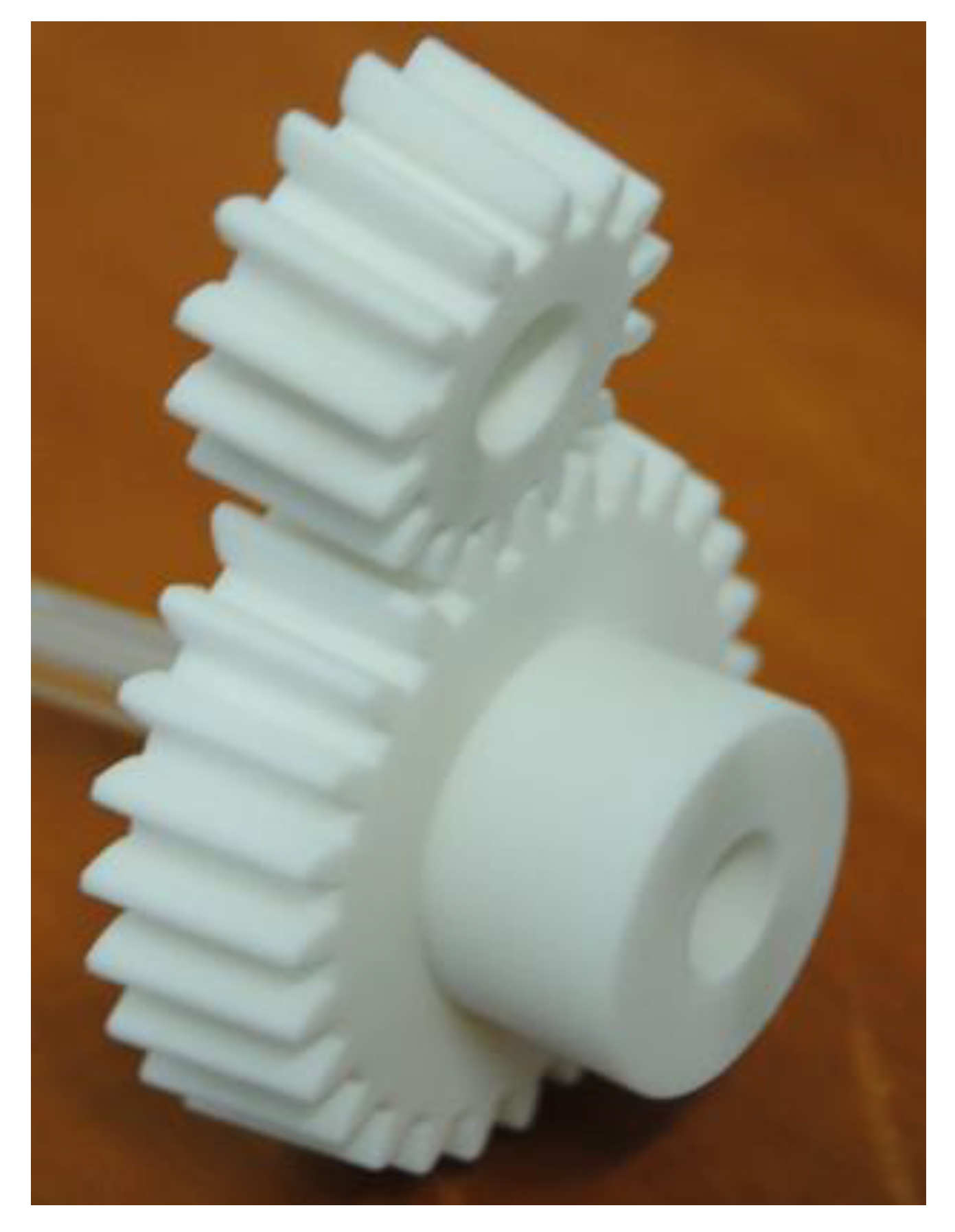
A 3D printed prototype is shown in Figure 10. This prototype has been successfully mounted at the wrist of the EasyLap operating arm. Figure 11 shows the sterilizable component of the adaptor for standard laparoscopic instruments using the designed couple of small size bevel gears.

6. Conclusions

This paper has proposed a semi-automated design algorithm for computing straight bevel gear involute profiles by taking into account a 3D printing manufacturing process. The proposed formulation relies on Tredgold approximation, and is suitable for any desired number of teeth and relative axes inclination angles. A specific case study was carried out to design a miniaturized bevel gear pair in order to minimize the encumbrance for a new laparoscopic robotic system, EasyLap. A meshing analysis and a finite element-based tooth contact analysis were carried out in order to evaluate the behavior of the geared transmission under a set of different loads that did not overcome the applied working conditions. The numerical simulations demonstrated that the proposed non-traditional design approach provides conjugate tooth profiles of the contacting surfaces as well as their suitable vibrational performances. The latter are properly used to guarantee high precision for biomedical applications. Finally, a prototype was also built and successfully installed on an EasyLap robotic system, proving engineering feasibility and effectiveness of the proposed design procedure. Future developments will extend the proposed algorithm, including an STE-based optimization in the calculation of the radii and angles.

Author Contributions

Conceptualization, A.A., G.F., P.F.G., and G.D.; Investigation, G.D.; Methodology, A.A. and G.D.; Supervision, D.M., G.C., and G.D.; Visualization, A.A.; Writing— original draft, A.A.; Writing— review and editing, D.M., G.C., and G.D..

Acknowledgments

This work was performed under project EasyLap, POR Calabria 2014-2020 Fesr-Fse, CUP J28C17000130006. The authors wish to acknowledge the help of Gianluca La Greca and Basilio Sinopoli for preparing the CAD model and printing the prototypes of the bevel gears. The authors gratefully acknowledge Siemens Industry Software NV (Belgium) for the valuable technical support.

Conflicts of Interest

The authors declare no conflict of interest.

References

  1. Kalk, H.; Brühl, W. Leitfaden der Laparoskopie und Gastroskopie; Georg Thieme Verlag: Stuttgart, Germany, 1951. [Google Scholar] [CrossRef]
  2. Berci, G.; Cuschieri, A. Practical Laparoscopy; Bailliere Tindall: London, UK, 1986. [Google Scholar]
  3. Diaz-Arrastia, C.; Jurnalov, C.; Gomez, G.; Townsend, C. Laparoscopic hysterectomy using a computer-enhanced surgical robot. Surg. Endosc. Other Interv. Tech. 2002, 16, 1271–1273. [Google Scholar] [CrossRef] [PubMed]
  4. Advincula, A.; Song, A.; Burke, W.; Reynolds, R. Preliminary Experience with Robot-Assisted Laparoscopic Myomectomy. J. Am. Assoc. Gynecol. Laparosc. 2004, 11, 511–518. [Google Scholar] [CrossRef]
  5. Di Marco, D.; Chow, G.; Gettman, M.; Elliott, D. Robotic-assisted laparoscopic sacrocolpopexy for treatment of vaginal vault prolapse. Urology 2004, 63, 373–376. [Google Scholar] [CrossRef] [PubMed]
  6. Sackier, J.M.; Wang, Y. Robotically assisted laparoscopic surgery. From concept to development. Surg. Endosc. 1994, 8, 63–66. [Google Scholar] [CrossRef] [PubMed]
  7. Reichenspurner, H.; Damiano, R.J.; Mack, M.; Boehm, D.H.; Gulbins, H.; Detter, C.; Meiser, B.; Ellgass, R.; Reichart, B. Use of the voice-controlled and computer-assisted surgical system ZEUS for endoscopic coronary artery bypass grafting. J. Thorac. Cardiovasc. Surg. 1999, 118, 11–16. [Google Scholar] [CrossRef]
  8. Babbar, P.; Hemal, A.K. Robot-assisted urologic surgery in 2010—Advancements and future outlook. Urol. Ann. 2011, 3, 1–7. [Google Scholar] [PubMed]
  9. Fragomeni, G.; Gatti, G.; Greco, P.F.; Nudo, P.; Perrelli, M.; Sinopoli, B.; Rizzuto, A.; Danieli, G. EasyLap—New robotic system for single and multiple access laparoscopy using almost only traditional laparoscopic instrumentation. In Proceedings of the International Symposium of Mechanism and Machine Science, Baku, Azerbaijan, 11–14 September 2017. [Google Scholar]
  10. Vivet, M.; Mundo, D.; Tamarozzi, T.; Desmet, W. An analytical model for accurate and numerically efficient tooth contact analysis under load, applied to face-milled spiral bevel gears. Mech. Mach. Theory 2018, 130, 137–156. [Google Scholar] [CrossRef]
  11. Dooner, D.B.; Vivet, M.; Mundo, D. Deproximating Tredgold’s Approximation. Mech. Mach. Theory 2016, 102, 36–54. [Google Scholar] [CrossRef]
  12. Uicker, J.J.; Pennock, G.R.; Shigley, J.E. Theory of Machines and Mechanisms; Oxford University Press: New York, NY, USA, 2017. [Google Scholar]
  13. Litvin, F.L.; Fuentes, A. Gear Geometry and Applied Theory; Cambridge University Press: New York, NY, USA, 2004. [Google Scholar]
  14. Gupta, K.; Jain, N.K.; Laubscher, R. Advanced Gear Manufacturing and Finishing, Classical and Modern Processes; Academic Press: London, UK, 2017. [Google Scholar]
  15. Ozel, C.; Inan, A.; Ozler, L. An investigation on Manufacturing of the Straight Bevel Gear using End Mill by CNC Milling machine. J. Manuf. Sci. Eng. 2005, 127, 503–511. [Google Scholar] [CrossRef]
  16. Shih, Y.-P. Mathematical model for Face-Hobbed Straight Bevel Gears. J. Mech. Des. 2012, 134. [Google Scholar] [CrossRef]
  17. Kapelevich, A. Gear design: Breaking the status quo. Mach. Des. 2007, 79, 89–93. [Google Scholar]
  18. Vivet, M.; Heirman, G.H.K.; Tamarozzi, T.; Desmet, W.; Mundo, D. An Ease-off Based Methodology for Contact Detection and Penetration Calculation. In Proceedings of the International Conference on Power Transmissions, Chongqing, China, 27–30 October 2016. [Google Scholar]
  19. Smith, J.D. Gear Noise and Vibration; Marcel Dekker Inc.: New York, NY, USA, 2003. [Google Scholar]
  20. Elkholy, A.H.; Elsharkawy, A.A.; Yigit, A.S. Effect of Meshing Tooth Stiffness and Manufacturing Error on the Analysis of Straight Bevel Gears. J. Mech. Struct. Mach. 1998, 26, 41–61. [Google Scholar] [CrossRef]
  21. Korta, J.A.; Mundo, D. Multi-objective micro-geometry optimization of gear tooth supported by response surface methodology. Mech. Mach. Theory 2017, 109, 278–295. [Google Scholar] [CrossRef]
  22. Wriggers, P. Computational Contact Mechanics; John Wiley and Sons: Chichester, UK, 2002. [Google Scholar]
  23. Advanced Nonlinear Solution—Theory and Modeling Guide; NX Nastran 10; Siemens Product Lifecycle Management Software Inc.: Plano, TX, USA, 2014.
Figure 1. Pitch cones of the gear pair elements.
Machines 07 00038 g001
Figure 2. Logical sequence of the proposed semi-automated design method.
Machines 07 00038 g002
Figure 3. Overview of major steps of the tooth flank generation process.
Machines 07 00038 g003
Figure 4. (a) Single tooth finite element mesh; (b) complete gear finite element mesh.
Machines 07 00038 g004
Figure 5. The finite element model of the analyzed straight bevel gear pair.
Machines 07 00038 g005
Figure 6. (a) Constraint function without contact compliance; (b) constraint function with contact compliance, according to the method described in [23].
Machines 07 00038 g006
Figure 7. Static transmission error (STE) curves of the bevel gear pair under different loading conditions.
Machines 07 00038 g007
Figure 8. STE curve for 1 Nm.
Machines 07 00038 g008
Figure 9. Contact patterns of two consecutive steps along the mesh cycle: (a) when two pairs of teeth are in contact; (b) when one pair of teeth is in contact.
Machines 07 00038 g009
Figure 10. 3D printed prototypes of the bevel gear pair elements.
Machines 07 00038 g010
Figure 11. 3D printed adaptor for traditional surgical instruments using this gear pail.
Machines 07 00038 g011
Table 1. Blank data of the example bevel gear pair.
Gear Data PinionGear
Number of teeth 1427
(mfc, mbc)(mm)(0.9, 1)(0.9, 1)
n 8181
Face width(mm)9.7979.797
Mean cone distance(mm)93.00393.003
Pressure angle(°)2020
Pitch radius at midpoint(mm)3.3186.694
Table 2. Calculated peak-to-peak values under different loading conditions.
Peak-to-Peak STE (μrad)
0.01 Nm0.1 Nm0.5 Nm1 Nm
22.6723.6543.3573.10

