Abstract
The overturning stability and vibration of upland crop machinery under development are important issues for analysis because farms for upland crops are usually uneven, which may cause work-related fatalities, and vibration affects user comfort and reduces the durability of components. In this study, the overturning stability and vibration of a tractor-mounted radish collector were investigated to ensure safety during radish collection. To analyze lateral stability, the center of gravity (CG) of the tractor-mounted radish collector system was calculated mathematically. Then, a simulation was performed to determine the lateral overturning angles at different folding positions of the radish conveyor belt and load conditions, and the results were validated through tests. Vibration sensors were used to measure the vibration levels and the power spectrum density (PSD) was obtained to check the cyclic apparatuses of the major frequencies. The load conditions, different conveyor speeds, and locations were considered as factors affecting the vibration levels. Considering the physical parameters of the tractor–collector system, the analytical overturning angle was 30.5°. The average overturning angle difference between the simulation and validation was 5°, and the difference between loaded and unloaded conditions was 2°. For 0, 45, and 90° folding positions of the conveyor belt, overturning angles increased and varied from 0.5 to 1°. The vibration level was greater under the unloaded conditions and increased with an increase in the conveyor speed. Vibrations under the loaded condition (0.37~0.48 ms−2) satisfied the ISO (International Organization for Standardization) standard (except the first conveyor belt). According to the PSD analysis, high magnitude peaks (>25 dB) appeared frequently in all directions, which indicates a high possibility of damage to the first conveyor belt. This study provides useful information for improving the safety and durability of agricultural machinery for uneven and sloped field conditions.
1. Introduction
Radishes (Raphanus raphanistrum subsp. sativus) are one of the most popular vegetables in many South Asian countries (e.g., Korea, Japan, China, India), and the annual production of radishes in Korea, Japan, and China in 2018 was 0.467, 1.328, and 44.600 million tons, respectively [1,2,3]. It is an annual or biennial crop grown in open fields. Radishes are rich with vitamins, minerals, and other beneficial components (i.e., glucosinolates, isothiocyanates, anthocyanins) [4,5,6]. Nevertheless, the rate of radish cultivation is decreasing in many countries, such as the 19.5% yield and 18% acreage of daikon radish having decreased in Japan from 2006 to 2018 [2] due to the associated labor-intensive and time-consuming cultivation process, reduction in workforce as a result of aging, increasing labor wage, and low mechanization of the process [7,8,9]. Plantation, inter-cultivation operations, and harvesting all require a lot of labor. Manual harvesting, collecting, and packaging of radishes are the most labor-intensive processes. The mass of each harvested radish varies from 1 to 3 kg, and they all need to be pulled out, collected, and carefully transported to avoid damage. The ratio of labor in harvesting and transporting work is about 26.7% [10], and the mechanization rate of upland crop harvesting is 13.3% [10,11]. Therefore, radish collectors are in urgent demand in many countries for mechanized harvesting and collection operations [12,13,14]. Overturning stability and vibration levels need to be seriously considered with respect to field machinery because farms for upland crops are usually uneven and sloped, which may cause work-related fatalities, and vibration affects operator comfort and also reduces the durability of machinery components.
Failure of the overturning stability of agricultural field machinery is a major cause of farming incidents, which comprise a large segment of agricultural machinery hazard statistics, and the result may be serious injuries or the death of operators. The rollover tendency of agricultural field machinery is dependent on the stability, and the stability is related to the static, dynamic, and operational parameters of the machinery. Static and dynamic parameters are affected by wheelbase, tread width, and center of gravity, and the operating parameters are related to forward speed, turning radius, slope of the land, and surface conditions [6]. Rollover can occur in the lateral or longitudinal directions under static or operational conditions. Among several approaches used for determining static stability angles, two commonly used methods are (a) theoretical calculation of the center of gravity (CG) and stability angles, and (b) direct measurement of the tilt angle for vehicle overturning. The CG of machinery is directly linked with the dimensions and mass, and the static stability angle depends on the vertical height of the center of gravity. The axle lifting method is used to measure the vertical height, where the front axle is raised and the vertical height is calculated from the shift in mass of the vehicle between the front and rear axles [15]. A stability index was developed in 1999 by combining the static stability angles and operating slopes [15,16]. On the other side, dynamic stability is influenced by operational conditions. Angle sensors and accelerometers are used to measure the dynamic stability characteristics. According to the ISO 16231-2, the stability angles vary from 15 to 45° for different agricultural machinery [17]. To reduce the overturning risk and increase farming efficiency, the maximum recommended slope is 15° for agricultural machinery operation in Korea and Japan [14]. The stability angle also changes with the carrying load [18]. Movement of internal fluids may affect the constancy of the center of gravity. However, this has been investigated and marked as a negligible issue by several researchers [19,20].
Vibration affects user comfort and machinery durability, and also partially affects the stability [21,22,23]. Excessive vibration impedes the collection of crops. It usually occurs due to rapid forward, backward, or oscillating movement of the mechanical components. The vibration level may differ as a result of component speed, position, loading condition, operational site, and environmental factors [24,25,26]. The measurement of vibration is essential for maintaining stability (static, couple, dynamic, and overhung); reducing dynamic stress; preventing misalignment (belt and shaft), looseness, and resonance; and improving the overall working environment and maintaining the safety of off-road agricultural machinery or vehicles. According to the vibration regulations, the amount of daily exposure to whole-body vibration is 0.5 ms−2 and should not exceed 1.15 ms−2 [22,27]. The action vibration levels of the tractors with implements were in a range of 0.4~0.8 ms−2 [28]. Generally, vibration is measured according to the direction (axis), along with the intensity, frequency, and duration parameters [29]. The detailed vibration measuring process, site characteristics, and frequency level are described in ISO 5008:2002 [30]. However, little similarity was observed between the results of ISO for the whole body vibration and field tests performed following the same standardized speeds and tracks [24].
Stability analysis is required for identifying the rollover slope angle, operational safety, operator awareness, and emergency rescue operations. Vibration measurement is necessary to understand the fault conditions of machinery and improve the overall user comfort during operations. A tractor-mounted four-row radish collector was under development in this study. The objectives of this study were to determine the lateral overturning angles through simulation and validation tests considering different folding positions of the conveyor belt for both loaded and unloaded conditions, and to evaluate vibration levels at different locations of the radish collector considering speeds of the conveyor belts and load conditions during field operation.
2. Materials and Methods
2.1. Structure and Working Principle of the Radish Collector
A four-row radish collector was designed so that it could be mounted through the three-point hitch in the rear of a tractor (Figure 1). It consisted of four major components, namely two furrow guides, two conveyor belts, one stem cutter, and a storing container frame for keeping the collected radish. The overall length, width, height, and mass of the radish collector were 4210, 1200, and 2000 mm, and 460 kg, respectively. Farmers manually pulled out the radishes from the soil and placed them on the first conveyor. A stem cutter was placed at the end of the first conveyor to cut the stem of the radish. After cutting the stem, the inclined second conveyor carried the radish to the storing section, and radishes were collected in the bag. Around 30 radishes could be loaded on the conveyor belts at a time. The stem cutter and the first and second conveyor belts were operated by electric motors powered by a 12 V battery. The radish collector also contained a radish collecting bag. A rollover protective structure (rectangular safety frame) was welded vertically in the middle of the radish-collector to prevent the damage of the collector and minimize the injuries of laborers during rollover. The detailed specifications of the tractor-mounted radish collector system are presented in Table 1.
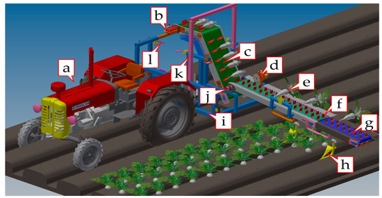
Figure 1.
3-dimensional model of the tractor-mounted radish collector system showing the major components: (a) tractor, (b) second conveyor motor, (c) second conveyor belt, (d) stem cutter (e) radish, (f) rubber bit, (g) first conveyor belt, (h) furrow guide, (i) collector-base, (j) first conveyor motor, (k) safety frame, and (l) hanging rods of the radish collecting bag.

Table 1.
Specifications of the tractor and radish collector.
2.2. Overturning Stability of the Tractor–Collector System
Among several factors that cause agricultural machinery hazards, overturning stability has a significant influence on safety. Determination of the center of gravity, mathematical calculation or simulation of the static or dynamic overturning angles, and validation tests are essential for stability analysis [14,15,16].
2.2.1. Determination of the Center of Gravity
The CG is an assumed point where the whole mass of the agricultural field machinery is concentrated. Suggested theoretical procedures [17] and methods [14,15,31] were followed to determine the CG of the tractor (CGT: XT, YT, ZT) and tractor-mounted radish collector system (CGS: XS, YS, ZS). As the radish collector did not have supporting wheels and the tractor carried the whole mass, the whole system was assumed to be a single rigid body. Figure 2 shows CG changes under an inclined condition. The mass distribution of the tractor with and without the radish collector was also measured to determine the CG; these results are presented in Table 2. Equations (1)–(3) and (4)–(6) were used for calculating the CG of the tractor and tractor–collector system, respectively.
where WTF1, WTF2, WTR1, and WTR2 refer to the mass of two front (F) and two rear (R) wheels, δ is the tilt angle, L1 is the wheelbase, W(L/R)2f1 is the load on the front wheel when lifted up, WT is the mass of tractor, WS is the mass of whole system, W1 and W2 are the lengths of front and rear axles, respectively, and r1 and r2 are the radii of the rear and front wheel, respectively.
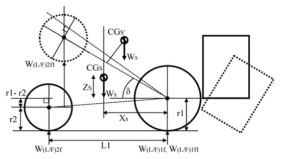
Figure 2.
Schematic diagram for center of gravity (CG) determination of the tractor–collector system under normal and inclined conditions.
Table 2.
Mass distribution of the tractor and tractor with radish collector.
2.2.2. Estimation of the Transverse Overturning Angle
Transverse overturning is defined as rollover occurring in the reverse direction [14]. Usually, it occurs when a vehicle is subjected to lateral forces, such as wind or seismic forces, but field slope is a major factor for the transverse overturning of agricultural machinery. The mathematical analysis of transverse overturning was conducted based on Equation (7), which is a summation of the coordinates (XS, YS, ZS) of the center of gravity, wheelbase (L1), and the deflection angle (γ). The deflection angle was changed from 0 to 360° at 10° intervals. The deflection angle was increased in a counterclockwise direction.
2.2.3. Identification of the Lateral Overturning Angles through Simulation and Validation
Simulation was performed to determine the lateral overturning angles at different folding positions of the radish conveyor belt and load conditions. In this study, a 3D prototype of the tractor-mounted radish collector system was drawn using commercial software (Recurdyn V9R2, FunctionBay, Gyeonggi-do, Korea). The simulation was conducted specifying all the required parameters, and lateral overturning angles were determined for different folded positions of the conveyor belt and load conditions. Here, load conditions are indicated by the mass of the tractor operator (83 kg) and total mass of the harvested radishes (45 kg). The factors considered during the simulation are presented in Table 3.
Table 3.
Factors considered during the simulation of lateral overturning stability of the tractor–collector system.
The lateral overturning of the tractor–collector system was validated at the Foundation of Agricultural Technology Commercialization and Transfer (FACT), Iksan, Korea. Three replications were applied for each condition. The mass on each wheel of the tractor and tractor with the radish collector were measured separately. The geometric dimensions of the tractor and radish collector were also recorded. Figure 3 shows the (a) simulation and (b) validation of lateral overturning without load and at a 0° folding angle of the conveyor belt. The right-side validation tests could not be performed because of some facility limitations.
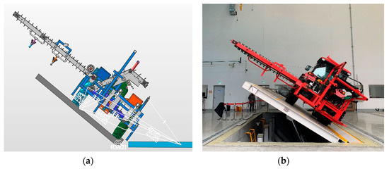
Figure 3.
Lateral overturning stability: (a) simulation and (b) validation of the tractor–collector system at 0° folding position of the conveyor belt and without load.
2.3. Vibration Measurement of the Tractor–Collector System
The sources of vibration of agricultural machinery are engine, transmission, and other processing units. In this study, vibration was measured using acceleration sensors (model: 356A15, PCB Piezotronics Inc., Depew, NY, USA) at three locations of the collector, namely collector base, first conveyor belt, and second conveyor belt. During the field operation, the acceleration levels were measured in three directions (X—longitudinal, Y—transverse, and Z—vertical). The average weighted vibration/acceleration (AW) was calculated using Equation (8), and the total acceleration (AV) was calculated from Aw using Equation (9) and considering the ISO 2631-1 standard [32]. Vibration sensors were interfaced with a data-acquisition module (model: NI USB-6234, National Instruments, Austin, TX, USA), and the LabVIEW (version: 2017, National Instruments, TX, USA) program was used for data acquisition. Data measurement was performed using a sampling frequency of 1000 Hz.
where aw,axis is frequency-weighted acceleration (ms−2) at a time t for the X, Y, and Z axes; T is the total duration of measurement; Aw,axis refers to average weighted acceleration (ms−2); AV is the total acceleration value (ms−2).
Acceleration and velocity both affect the vibration measurement. For example, in earthquake engineering, both the maximum acceleration and velocity values are correlated with building damage [33]. Similarly, the velocity of the conveyor belt was considered as an important factor in vibration testing. Three conveyor velocities (0.10, 0.16, and 0.20 ms−1) were selected for checking the vibration level variations. Vibration variation was also checked with and without radishes. The forward speed of the tractor was 0.20 ms−1 during the radish harvesting period.
In some cases, vibration can be affected by unconsidered sources, which might not be related harmonically. The future behavior of this type of random vibration could also not be adequately anticipated and preciously predicted [34]. Hence, power spectrum density (PSD) analysis was performed to investigate and better understand the repetition of the random vibration to predict the level of damage to collector components.
2.3.1. Fast Fourier Transform (FFT)
In order to transform the vibration signal from the time domain to the frequency domain, the FFT technique was applied [35,36], as shown in Equation (10):
where : a primitive Nth root of 1; N: memory length; x[N]: discrete-time signal, which is represented by a vector with N complex components; f: discrete frequency.
2.3.2. Power Spectral Density (PSD)
PSD is a scalar function that shows the distribution pattern (variations of strong and weak frequencies) of the time signal energy for various frequencies [37]. It is widely used in research in situations where FFT is unable to describe the non-stationary vibration signal. In this study, FFT was first applied and PSD was then analyzed directly from the frequency domain [38,39].
where f: obtained frequency from FFT; root mean square of acceleration of the obtained frequency (f). For the vibration measurement, a field test was performed in a farmer’s field (Pyeongchang-gun, Gangwon province, Korea). The length and width of the field were 50 and 16 m, respectively. Row-to-row and plant-to-plant distances were 70 and 20 cm, respectively. The swath of the four-row radish collector was 120 cm. The field slope was about 4.15° where, based on the field condition, 10~12° slope is allowed for field operations for upland crops in Korea (Figure 4).
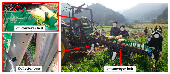
Figure 4.
Positions of the vibration sensors in the radish collector during the field test.
2.4. Statistical Analysis
For stability analysis, data were averaged, and the standard deviation (SD) was calculated. During vibration analysis, pre-processing of the raw data was carried out to remove noise and outliers. The vector sum (Av) was expressed with the standard deviation and statistical differences were determined by Tukey’s two-way ANOVA at a confidence level of 5%. PSD analysis was performed using the Fourier and anti-Fourier transform via MATLAB (version: R2013b, MathWorks, Natick, MA, USA).
3. Results
3.1. Overturning Stability
3.1.1. Center of Gravity
The CG of the tractor (CGT: XT, YT, ZT) and tractor–collector system (CGS: XS, YS, ZS) were determined using the measured parameters of Equations (1) to (6). According to Table 2, the mass of the tractor was 3052 kg, of which 46.92% and 53.08% of the mass was carried by the front and rear wheels, respectively. The total measured mass of the tractor–collector system was 3641 kg, of which 28.87% of the mass was distributed to the front wheels and 71.13% to the rear wheels. The mass ratios between the left and right wheels of the front and rear axles of the tractor–collector system were 49.86:50.14 and 50.25:49.75, respectively, and were almost symmetrical on each axle. The CGT coordinates of the tractor (XT, YT, ZT) were 1124, 129, and 972 mm, and the CGS coordinates of the tractor–collector system (XS, YS, ZS) were 628, 71, and 963 mm, respectively.
3.1.2. Transverse Overturning Angle
Mathematical analysis of the transverse stability of the tractor–collector system under the loaded condition was conducted using Equation (7) with a 10° counterclockwise increment of the declination angle (γ) over a range of 360°. Figure 5 shows the radiating circle, which represents the overturning angle direction of the radish collecting system. Right lateral overturning occurred when the tilt angle was at least 30.5°, and the range of deflection angles was from 80 to 260° counterclockwise. In addition to this, left lateral overturning also occurred when the tilt angle was at least 30°, and the range of deflection angles was from 260 to 80° counterclockwise.
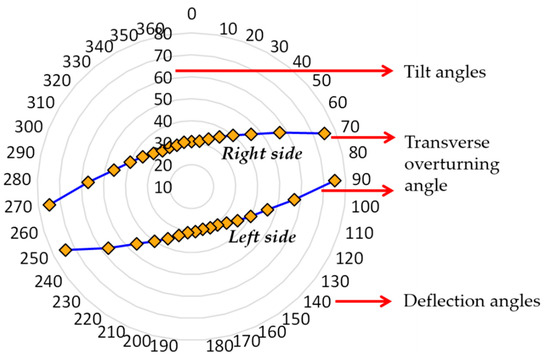
Figure 5.
Results of the transverse lateral overturning with 10° increment of the deflection angle.
3.1.3. Lateral Overturning Angle
Lateral overturning angles were determined through simulation considering different folding positions of the conveyor belt under unloaded and loaded conditions, and the left side overturning angles were validated through tests as illustrated in Figure 6. The average right and left side overturning angles determined by simulation under unloaded and loaded conditions were 52.06°, 37.12°, and 49.01°, 34.96°, respectively. Furthermore, 32° was the average validated overturning angle on the left side (except the 0° folded condition of the conveyor because the expanded conveyor touched the platform at 15° during the overturning tests).
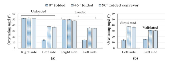
Figure 6.
Lateral overturning angles of the tractor–collector system: (a) simulated overturning angles under unloaded and loaded conditions, and (b) angle difference between simulation and validation.
3.2. Vibration Evaluation of the Tractor–Collector System
The vector sum of the measured vibration on the collector base and first and second conveyor belts of the radish collector under unloaded and loaded conditions, and 0.10, 0.16, and 0.20 ms−1 conveyor speeds are shown in Table 4. Average vibration was lower under the loaded condition compared to the unloaded condition (except the first conveyor belt). The averaged vibration difference between the unloaded and loaded condition was −0.92, 2.27, and −0.77 ms−2 (where the − sign indicates a reduction in vibration) for the collector base, first conveyor, and second conveyor, respectively. According to Tukey’s two-way ANOVA analysis, no significant vibration impact was observed between the sensor locations and conveyor speeds under the unloaded condition (F(2,2) = 4.05, p = 0.109), but a significant difference was observed for the loaded condition (F(2,2) = 7.79, p = 0.041).
Table 4.
Vector sum of the measured vibration on different locations of the radish collector for different conveyor speeds and load conditions.
Figure 7 shows the maximum measured vibration levels regarding the X, Y, and Z axes in the conveyor base, first conveyor belt, and second conveyor belt for the 0.10, 0.16, and 0.20 ms−1 conveyor speeds, and unloaded and loaded conditions. Similar vibration levels were observed under the unloaded condition of the radish collector (Figure 7a). Therein, the highest vibration (4.63 ms−1) was observed in the second conveyor belt. Figure 7b shows the vibration levels during the loaded condition. Random vibrations with high standard deviation were observed in the first conveyor belt compared to the conveyor base and second conveyor belt. Therefore, PSD analysis was performed to investigate and understand the repetition of this random vibration.
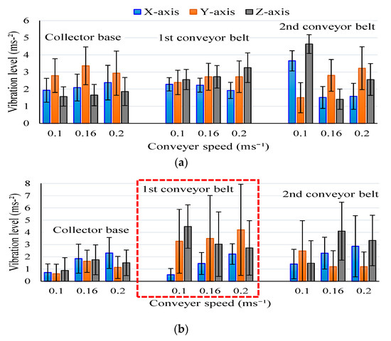
Figure 7.
Maximum vibration levels in different positions of the radish collector and speeds of the conveyor belts during (a) unloaded condition and (b) loaded condition.
The power spectrum of the three directions (X—longitudinal, Y—transverse, and Z—vertical) for 0.10, 0.16, and 0.20 ms−1 conveyor speeds under the loaded condition of the first conveyor belt is shown in Figure 8. The frequency range in the X axis was 0 to 1000 Hz, and the Y axis represents the power spectrum in 20log10 (W/Hz) scale. High magnitude peaks are observed for all conveyor speeds in all directions; however, the frequent emergence of peaks is observed for the 0.16 ms−1 conveyor speed in the Y direction. All high magnitude peaks were around 30 dB, which indicated a high probability of damage to the first conveyor belt and hampering of user comfort.
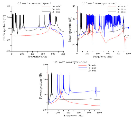
Figure 8.
Power spectrum density (PSD) analysis of the measured vibration on the first conveyor belt for 0.10, 0.16, and 0.20 ms−1 conveyor speeds and loaded condition.
4. Discussion
The possibility of agricultural field machinery rollover mainly depends on the center of gravity. In this study, the gravity coordinates of the tractor (XT, YT, and ZT) were moved by 495, 59, and 9 mm, respectively, after attaching the radish collector. The change in X and Y coordinates indicates a transfer of CG near to the rear wheel axle of the tractor due to the non-supporting self-mass of the radish collector. A reduction in the Z coordinate reduces the overturning possibility partially because agricultural field machinery with a high-situated CG rolls over more frequently than agricultural machinery with a lower-positioned CG [40,41]. A similar result was observed by [31]. The gravity coordinates changed from 957, −9, 783 mm to 102, 402, 770 mm after hitching the harvester in their experiment. However, the coordinates of CG change in a different direction when the mass of the attached implement is supported independently [14].
According to the ISO 16251-2 [17], the allowable range of the overturning angle is 15 to 45° based on different off-road agricultural field machinery. In this study, stability angles varied from 30 to 52° in the unloaded condition, and 35 to 49° in the loaded condition for the different folded positions of the conveyor belt, which is very close to the ISO recommendation. The difference between the simulated and validated left-sided overturning angle was 5°. As the simulated left-sided overturning angles were almost similar to the validated overturning angle, the right-sided simulated overturning angle would also be assumed to be correct (Figure 6). Validation tests with the loaded condition could not be performed due to some facility limitations. According to the simulation results, the difference between the loaded and unloaded conditions was 2°, which might not affect the stability of the tractor–collector system. A 5~7° angle variation was observed by [15] for different agricultural vehicles under the loaded and unloaded conditions. Furthermore, a 0.5~1° angle variation was observed for the 0, 45, and 90° folded position of the conveyor belt in overturning for both sides, which is also negligible compared to the overall overturning angle. Overall findings from the stability analysis indicate that the tractor–collector system could be operated comfortably on land with a slope of up to 30°.
According to the vibration regulations, the amount of daily exposure to whole-body vibration is 0.5 ms−2, and should not exceed 1.15 ms−2 [22]. In this study, the average vibration level under the loaded condition was 0.41 ms−2, which satisfies the ISO recommended exposure limit (0.5 ms−2), except in the case of the first conveyor belt. However, vibrations under the unloaded condition exceeded the maximum recommended exposure limit (1.15 ms−2) (Table 4). This indicates that the operation of the empty conveyor belts at any speed will face damage as well as degrade the working environment and user comfort. Vibration of the collector base and second conveyor belt was significantly reduced under the loaded condition; however, random and high vibration was observed in the first conveyor belt. The random patterns of vibration in the first conveyor belt were separately investigated through PSD analysis (Figure 8). Almost the same level of the power spectrum (around 30 dB) was observed in the X, Y, and Z axes for 0.1, 0.16, and 0.2 ms−1 conveyor speeds, but peaks emerged more frequently for 0.16 ms−1 conveyor speed, especially in the Y axis direction. Operation under this condition for a long time would increase the possibility of fatigue [42]. This vibration exposure is also transmitted to the second conveyor belt. Furthermore, the vibration level increased with the increasing speed of the conveyor belt in the loaded and unloaded conditions of the radish collector (Table 4). Similar findings were also observed by several researchers during the vibration analysis of agricultural vehicles and machinery [27,32,43]. The speed of each conveyor belt needs to be optimized based on radish collecting efficiency, possible damage intensity, and the overall working environment.
5. Conclusions
The present study focused on the evaluation of a tractor-mounted radish collector in terms of lateral stability and vibration exposure during the field operation. The coordinates of the CG and transverse overturning angles were determined mathematically. Then, simulation was carried out for different folded positions of the radish conveyor belt and load conditions, and validation was conducted to check and compare the results with the simulation. Different locations, conveyor speeds, and load conditions were considered during the vibration measurement of the tractor-mounted radish collecting system during the field operation. Based on the results of the mathematical calculation, the CG of the tractor–collector system (XS, YS, ZS) was 628, 71, and 963 mm, and the transverse overturning angle was 30.5°. A small (2~5°) difference was observed between the simulated and validated overturning angle and overturning in loaded and unloaded conditions. A negligible angle difference was observed for the 0, 45, and 90° folded positions of the conveyor belt. Overall findings from the stability analysis indicate that the tractor–collector system could be operated safely on up to 30° sloped land. Average vibration exposure under the loaded condition (0.41 ms−2) satisfied the ISO standards (0.5 ms−2), but a high magnitude of vibration was observed in the unloaded condition (1.01~1.66 ms−2), especially in the first conveyor belt in both conditions (1.59~4.43 ms−2), which indicates the possibility of severe damage to the components of the first conveyor belt and degradation of the working environment and user comfort. The conveyor joints and power transmission systems need to be improved to reduce vibration exposure. The findings of this study are helpful for improving stability, durability, and user comfort of agricultural machinery that is operated in uneven and sloped fields.
Author Contributions
Conceptualization, S.-O.C. and M.C.; methodology, S.-O.C.; software, M.C.; validation, M.C., M.N.I., M.Z.I., S.I.; formal analysis, M.C., M.N.I., M.Z.I., S.I.; investigation, S.-O.C., D.-H.L., D.-G.K., and H.-J.J.; resources, S.-O.C.; data curation, M.C., M.N.I., M.Z.I.; writing—original draft preparation, M.C.; writing—review and editing, S.-O.C., D.-H.L., and D.-G.K., and H.-J.J.; visualization, M.C., M.N.I., and S.I., and D.-H.L.; supervision, S.-O.C.; project administration, S.-O.C.; funding acquisition, S.-O.C. All authors have read and agreed to the published version of the manuscript.
Funding
This study was conducted with the support of the “Cooperative Research Program for Agriculture Science and Technology Development (project no. PJ012853042020)”, Rural Development Administration, Republic of Korea.
Conflicts of Interest
The authors declare that they have no conflict of interest.
References
- Zhang, J.; He, P.; Ding, W.; Xu, X.; Ullah, S.; Abbas, T.; Ai, C.; Li, M.; Cui, R.; Jin, C.; et al. Estimating nutrient uptake requirements for radish in China based on QUEFTS model. Sci. Rep. 2019, 9, 11663. [Google Scholar] [CrossRef]
- LLC, A. Daikon Radish—Japanese Agriculture|Japan CROPs. Available online: https://japancrops.com/en/crops/daikon-radish/ (accessed on 11 November 2020).
- Cultivated Area of Autumn Cabbages and Radishes in 2019. Available online: http://kostat.go.kr/portal/eng/pressReleases/2/2/index.board?bmode=read&aSeq=378915&pageNo=&rowNum=10&amSeq=&sTarget=&sTxt= (accessed on 24 September 2020).
- Banihani, S.A. Radish (Raphanus sativus) and Diabetes. Nutrients 2017, 9, 1014. [Google Scholar] [CrossRef] [PubMed]
- Ishida, M.; Kakizaki, T.; Morimitsu, Y.; Ohara, T.; Hatakeyama, K.; Yoshiaki, H.; Kohori, J.; Nishio, T. Novel glucosinolate composition lacking 4-methylthio-3-butenyl glucosinolate in Japanese white radish (Raphanus sativus L.). Theor. Appl. Genet. 2015, 128, 2037–2046. [Google Scholar] [CrossRef] [PubMed]
- Malik, M.S.; Riley, M.B.; Norsworthy, J.K.; Bridges, W. Variation of glucosinolates in wild radish (Raphanus raphanistrum) accessions. J. Agric. Food Chem. 2010, 58, 11626–11632. [Google Scholar] [CrossRef] [PubMed]
- Sakuragawa, M.; Makino, T. Labor Force Ageing and Economic Growth in Japan. In Ageing and the Labor Market in Japan; Koichi, H., Hiromi, K., Eds.; Edward Elgar Publishing: Cheltenham, UK, 2007; pp. 57–74. [Google Scholar]
- Oshio, T.; Usui, E.; Shimizutani, S. Labor Force Participation of the Elderly in Japan; National Bureau of Economic Research: Cambridge, MA, USA, 2018; p. w24614. [Google Scholar]
- Shin, S.Y.; Kang, C.H.; Yu, S.C.; Kim, Y.Y.; Noh, J.S. Criteria for determining working area and operating cost for long-term lease of agricultural machinery. J. Biosyst. Eng. 2015, 40, 178–185. [Google Scholar] [CrossRef][Green Version]
- Jung, Y.; Jeon, H.H.; Jung, H.J.; Choi, C.H.; Yong Joo, K. Finite element analysis of radish harvesting part. In Proceedings of the ASABE Annual International Meeting, Detroit, MI, USA, 29 July–1 August 2018. [Google Scholar]
- Ali, M.; Lee, Y.S.; Kabir, M.S.N.; Kang, T.K.; Lee, S.H.; Chung, S.O. Kinematic analysis for design of the transportation part of a tractor-mounted Chinese cabbage collector. J. Biosyst. Eng. 2019, 44, 226–235. [Google Scholar] [CrossRef]
- Liu, H.C.; Sung, W.P.; Yao, W. Current status and future strategy for the application of new technologies in agricultural mechanization. In Proceedings of the International Conference on Information Technology and Computer Application Engineering Press, Hong Kong, China, 12 June 2018. [Google Scholar]
- Cuddihy, W. Agricultural prices, farm mechanization, and the demand for labor. In Migration, Mechanization, and Agricultural Labor Markets in Egypt; Richards, A., Martin, P.L., Eds.; Routledge: Abingdon, UK, 2019; pp. 225–236. ISBN 978-0-429-04710-7. [Google Scholar]
- Hong, S.; Lee, K.; Kang, D.; Park, W. Analysis of static lateral stability using mathematical simulations for 3-axis tractor-baler system. J. Biosyst. Eng. 2017, 42, 86–97. [Google Scholar] [CrossRef]
- Paul, A.; John, C.; Rob, C.; Pau, T. Stability analysis of agricultural off-road vehicles. J. Agric. Saf. Health 2018, 24, 167–182. [Google Scholar] [CrossRef]
- Liu, B.; Koc, A.B. Field tests of a tractor rollover detection and emergency notification system. J. Agric. Saf. Health 2015, 113–127. [Google Scholar] [CrossRef]
- ISO 16231-2:2015 Self-Propelled Agricultural Machinery—Assessment of Stability—Part 2: Determination of Static Stability and Test Procedures. Available online: https://www.iso.org/cms/render/live/en/sites/isoorg/contents/data/standard/06/15/61583.html (accessed on 24 September 2020).
- ANSI/OPEI B71.4-2017—Commercial Turf Care Equipment—Safety Specifications. Available online: https://webstore.ansi.org/standards/opei/ansiopeib712017-1654115 (accessed on 24 September 2020).
- Wang, X. The influence of the lift angle on the center of gravity: Measurements for zero turning radius mowers. Appl. Eng. Agric. 2016, 32, 189–199. [Google Scholar] [CrossRef]
- Khorsandi, F.; Ayers, P.D.; Freeland, R.S.; Wang, X. Modeling the effect of liquid movement on the center of gravity calculation of agricultural vehicles. J. Terramech. 2018, 75, 37–48. [Google Scholar] [CrossRef]
- Rabbani, M.A.; Tsujimoto, T.; Mitsuoka, M.; Inoue, E.; Okayasu, T. Prediction of the vibration characteristics of half-track tractor considering a three-dimensional dynamic model. Biosyst. Eng. 2011, 110, 178–188. [Google Scholar] [CrossRef]
- Scarlett, A.J.; Price, J.S.; Stayner, R.M. Whole-body vibration: Evaluation of emission and exposure levels arising from agricultural tractors. J. Terramech. 2007, 44, 65–73. [Google Scholar] [CrossRef]
- Cutini, M.; Costa, C.; Bisaglia, C. Development of a simplified method for evaluating agricultural tractor’s operator whole body vibration. J. Terramech. 2016, 63, 23–32. [Google Scholar] [CrossRef]
- Deboli, R.; Calvo, A.; Preti, C. Comparison between ISO 5008 and field whole body vibration tractor values. J. Agric. Eng. 2012, 43, e8. [Google Scholar] [CrossRef]
- Gao, Z.; Xu, L.; Li, Y.; Wang, Y.; Sun, P. Vibration measure and analysis of crawler-type rice and wheat combine harvester in field harvesting condition. Trans. Chin. Soc. Agric. Eng. 2017, 33, 48–55. [Google Scholar]
- Xu, L.; Li, Y.; Sun, P.; Pang, J. Vibration measurement and analysis of tracked-whole feeding rice combine harvester. Trans. Trans. Chin. Soc. Agric. Eng. 2014, 30, 49–55. [Google Scholar]
- Krajnak, K. Health effects associated with occupational exposure to hand-arm or whole body vibration. J. Toxic. Environ. Health Part B 2018, 21, 320–334. [Google Scholar] [CrossRef]
- Gialamas, T.; Gravalos, I.; Kateris, D.; Xyradakis, P.; Dimitriadis, C. Vibration analysis on driver’s seat of agricultural tractors during tillage tests. Spanish J. Agric. Res. 2016, 14, 5. [Google Scholar] [CrossRef]
- Pang, J.; Li, Y.; Ji, J.; Xu, L. Vibration excitation identification and control of the cutter of a combine harvester using triaxial accelerometers and partial coherence sorting. Biosyst. Eng. 2019, 185, 25–34. [Google Scholar] [CrossRef]
- ISO 5008:2002—Agricultural Wheeled Tractors and Field Machinery. Measurement of Whole-Body Vibration of the Operator. Available online: https://shop.bsigroup.com/en/ProductDetail/?pid=000000000030142859&_ga=2.150491198.943613003.1601766954-1138060861.1601766954 (accessed on 4 October 2020).
- Choi, K.; Kim, S.M.; Hong, S. Analysis of static stability by modified mathematical model for asymmetric tractor-harvester system: Changes in lateral overturning angle by movement of center of gravity coordinates. J. Biosyst. Eng. 2017, 42, 127–135. [Google Scholar] [CrossRef]
- Kabir, M.S.N.; Chung, S.O.; Kim, Y.J.; Sung, N.S.; Hong, S.J. Measurement and evaluation of whole body vibration of agricultural tractor operator. Int. J. Agric. Biol. Eng. 2017, 10, 248–255. [Google Scholar] [CrossRef]
- Nakai, D.; Saito, K. A method for generating random vibration using acceleration kurtosis and velocity kurtosis. J. Appl. Pack. Res. 2019, 11, 64–74. [Google Scholar]
- Heidarbeigi, K.; Ahmadi, H.; Omid, M. Fault diagnosis of Massey Ferguson gearbox using power spectral density. In Proceedings of the 18th International Conference on Electrical Machines, Vilamoura, Portugal, 6–9 September 2008. [Google Scholar]
- Bracewell, R.N.; Bracewell, R.N. The Fourier Transform and Its Applications; McGraw-Hill: New York, NY, USA, 1986; Volume 31999, pp. 127–134. [Google Scholar]
- Khaksar, Z.; Ahmadi, H.; Mohtasebi, S.S. Whole body vibration analysis of tractor operators using power spectral density. J. Mech. Eng. Technol. 2013, 1, 6–12. [Google Scholar] [CrossRef]
- Rahman, M.M.; Ariffin, A.K.; Jamaludin, N.; Haron, C.H.C. Finite element based vibration fatigue analysis for a new free piston engine components. Arabian J. Sci. Eng. 2009, 34, 231–246. [Google Scholar]
- Irvine, T. Power Spectral Density Units: [ G^2 / Hz]. Revision B 2007. Available online: http://vibrationdata.com/tutorials2/psd.pdf (accessed on 24 September 2020).
- Howard, R.M. Principles of Random Signal Analysis and Low Noise Design: The Power Spectral Density and Its Applications; John Wiley & Sons: Perth, Australia, 2004; ISBN 978-0-471-46083-1. [Google Scholar]
- Fargnoli, M.; Lombardi, M. Safety vision of agricultural tractors: An engineering perspective based on recent studies (2009–2019). Safety 2020, 6, 1. [Google Scholar] [CrossRef]
- Reński, A. Investigation of the influence of the center of gravity position on the course of vehicle rollover. In Proceedings of the 24th International Technical Conference on the Enhanced Safety of Vehicles (ESV) National Highway Traffic Safety Administration, Gothenburg, Sweden, 8–11 June 2015. [Google Scholar]
- Hostens, I.; Ramon, H. Descriptive analysis of combine cabin vibrations and their effect on the human body. J. Sound Vib. 2003, 266, 453–464. [Google Scholar] [CrossRef]
- Kabir, S.N.; Song, M.Z.; Chung, S.O.; Kim, Y.J.; Kim, S.C.; Ha, J.K. Visibility evaluation for agricultural tractor operators according to ISO 5006 and 5721-1 standards. J. Biosyst. Eng. 2015, 40, 19–27. [Google Scholar] [CrossRef][Green Version]


Publisher’s Note: MDPI stays neutral with regard to jurisdictional claims in published maps and institutional affiliations. |
© 2020 by the authors. Licensee MDPI, Basel, Switzerland. This article is an open access article distributed under the terms and conditions of the Creative Commons Attribution (CC BY) license (http://creativecommons.org/licenses/by/4.0/).