1. Introduction
The harmonic drive reducer [
1,
2] is mainly composed of a wave generator (WG), flexspline (FS), and circular spline (CS), which is a type of gear transmission that makes the flexsplines produce controllable elastic deformation via the wave generator and engages with circular splines to transmit motion and power. With its advantages of high accuracy, low noise, light weight, and high speed ratio, the harmonic reducer is increasingly used in precision transmission fields for aerospace solar wing deployment mechanisms, antenna pointing mechanisms, scanning mechanisms, planetary lander traveling wheel drive mechanisms [
3,
4,
5,
6], robot joints, etc.
Figure 1 shows the basic structure of the simplest harmonic drive reducer.
Different from general gear transmission, the space harmonic gear transmission has obvious non-linear characteristics. Although designers have considered many factors affecting the transmission performance and made necessary analytical simulation in the initial design stage, it is difficult to accurately calculate the influence of working environment (such as irradiation, atomic oxygen, microgravity, etc.) on the performance of the mechanism, which results in different degrees of deviation between the simulation results and the actual situation. The actual performance of space harmonic reducer in space will directly affect the normal operation of spacecraft. Therefore, it is necessary to carry out reasonable analysis, modeling, and detailed test research on transmission error, backlash, torsional stiffness, efficiency, and dynamic friction moment of the space harmonic gear transmission link, so as to accurately study and describe the transmission performance of the space harmonic gear transmission system. Few scholars have made relevant research on this issue.
An accelerated life test of harmonic actuator was carried out in reference [
7], and an accelerated life test of liquid lubrication in mechanical part of spacecraft was carried out in reference [
8]. The lubrication performance of a strain wave transmission system in a space application was studied in [
9,
10]. The transmission errors of harmonic drive gears were studied in [
11,
12]. Torsional vibration caused by insufficient stiffness in the actuator of servo actuator, such as torsional vibration at the joint of robot in reference [
13]. Robust speed control was proposed in [
14,
15] to suppress the vibration caused by angle transmission error of planetary gear mechanism. The modeling and compensation method of the angular transmission error of harmonic driver were studied by M. Iwasaki et al. in [
16,
17,
18,
19]. Similar to this paper, reference [
20] designed a special test equipment for harmonic reducer, which carried out life evaluation tests for harmonic reducer of different grease lubrication in vacuum high temperature (90 °C), and tested the transmission efficiency of a harmonic reducer at different stages. The results show that the transmission efficiency decreases with the operation of harmonic reducer, and the test is terminated when the transmission efficiency decreases to 40%. Obviously, due to the friction face lubricant consumption and friction pair surface wear, resulting in the transmission efficiency with the test process in a downward trend. The results also show that MAC grease lubrication is better than PFPE grease lubrication. In order to obtain the environmental test data of harmonic reducer, reference [
21] conducted evaluation tests on solid lubrication and grease lubrication harmonic reducer in the vacuum high temperature (−150~+200 °C) environment. The transmission efficiency, stiffness and transmission accuracy were measured during the test, and the results show that the life of grease lubricated harmonic reducer is longer than that of solid lubricated harmonic reducer. The life of a harmonic reducer with large speed reduction ratio (1:160) is tested in [
22]. The size of the rigid and flexible gear of the harmonic reducer is small, and the wear resistance is relatively low. After the nitriding treatment, the surface hardness of the gear surface is improved, and then coats with grease for lubrication to obtain a good effect. Aiming at the application demand of space low temperature, reference [
23] developed a harmonic reducer for vacuum low temperature (−150 °C) environment. The test equipment of harmonic reducer was used to evaluate the stiffness, transmission efficiency and running lifetime of this harmonic reducer, so as to verify the output capacity (17,500 RPM) of the output shaft. In the paper [
24], by using the magnetic distance force interactions of magnets and ferromagnetic materials, all the conventional mechanical elements of a harmonic drives (teeth, flexspline, and ball bearings) are substituted by contactless mechanical components (magnetic gear and superconducting magnetic bearings). As the magnetic transmission is continuous there is no backlash in the reduction. The absence of contact between any moving parts prevents wear, lubricants are no longer required, and the operational life time is greatly increased.
However, the accelerated life test model established in the above papers is based on previous engineering experience and relevant literature, which cannot accurately reflect the performance of a space harmonic reducer in outer space. In order to get more accurate actual test data, an automatic test system was established in this paper, which uses a computer software and hardware system and related sensors to test the whole life cycle of a space harmonic reducer, and to process and analyze the data in real time as well. Furthermore, relevant experiments were carried out in high vacuum and low temperature equipment.
2. Hardware Composition of Performance Testing System for Space Harmonic Reducer
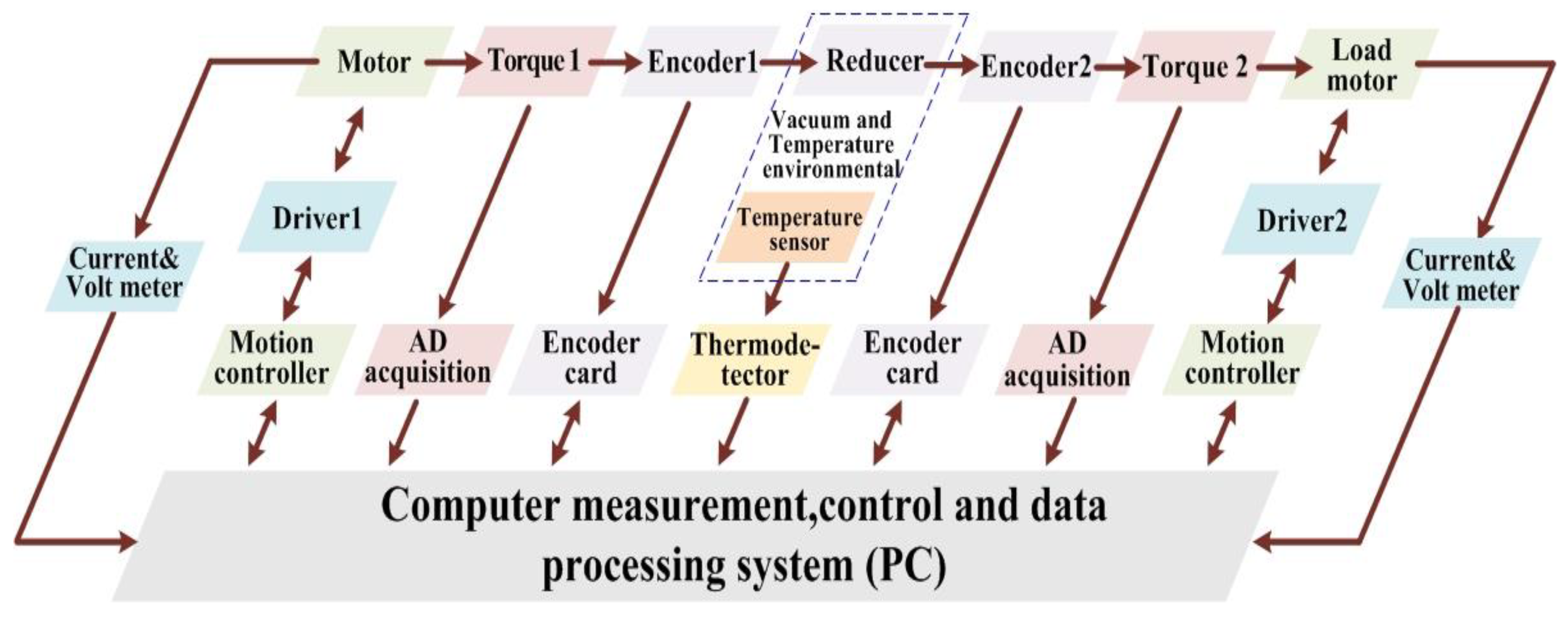
As shown in
Figure 2, the test system mainly includes drive module, high vacuum and low temperature component, tested component, and load component. For different test items, the appropriate components are selected to couple into the test system. When the test is carried out under normal temperature and pressure, the driving component, the tested component, and the loading component are directly connected.
The drive assembly includes servo motors, input torque and angle encoder, which are installed on the fixed bearing. The servo motor power is output after input torque sensor and angle encoder in turn.
The high vacuum and low temperature experimental component includes the input end magnetic fluid sealing shaft, vacuum tank, optical platform fixedly arranged in the vacuum tank, output end magnetic fluid sealing shaft, vacuum pumping system, temperature system, monitoring and control system, etc.
The load assembly includes the output end angle encoder, torque sensor, and torque motor which are respectively installed on the fixed support, and the power is input to the torque motor through the output end angle encoder and torque sensor in turn.
2.1. Hardware Principle of the System
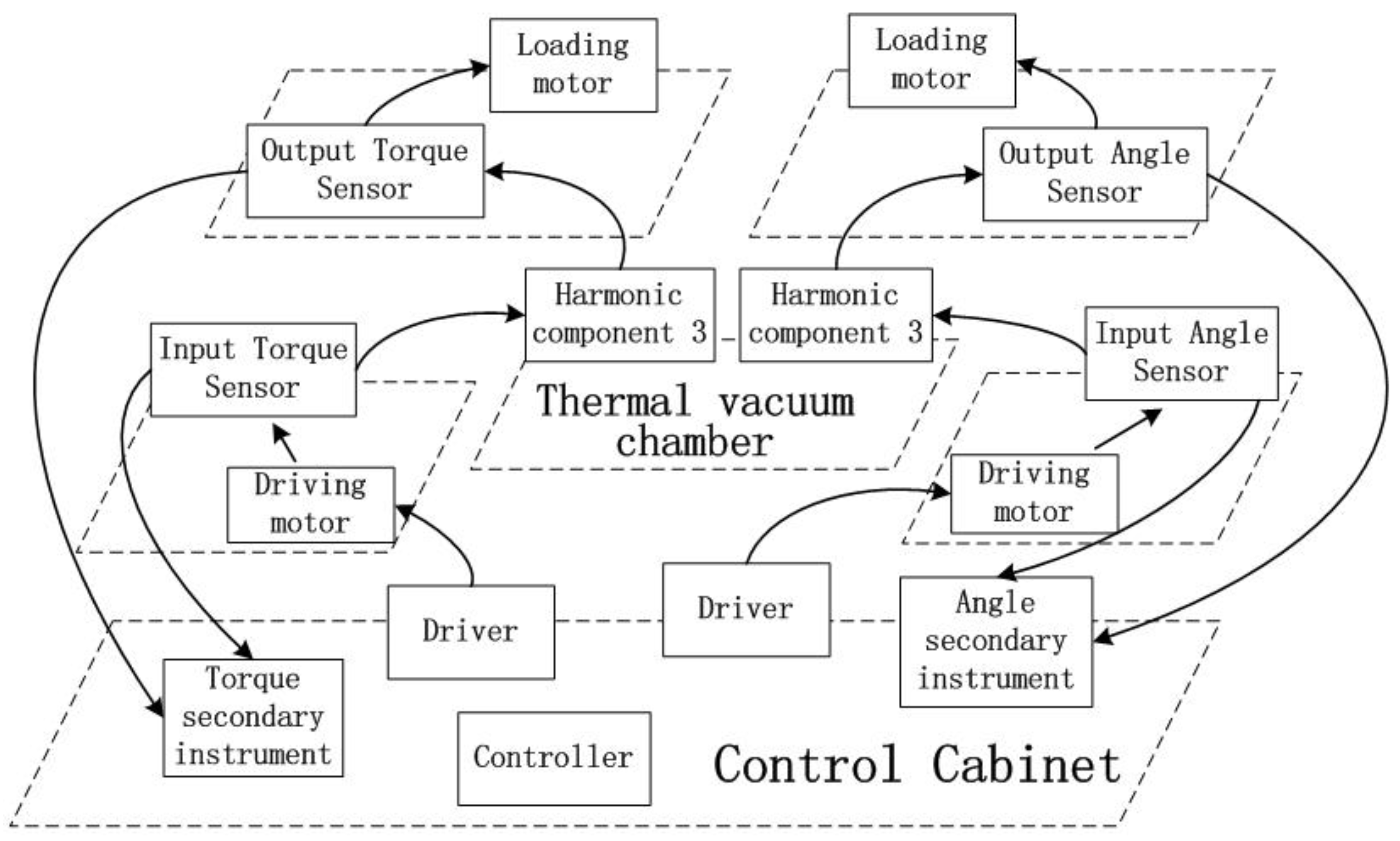
The overall hardware schematic of the space harmonic reducer performance test system is shown in
Figure 3.
The test cabinet of performance test device for space harmonic reducer is made up of 6 servo motors and drivers. The 6 drivers are connected by the CANOpen bus. Based on software, the host computer sends operation instructions to any main driver via CAN bus, so that the main driver can specify any motor action. The angle sensor can input the signal through the PCI card connected to the PCI slot of the host computer, and a PCI card has two channels, which can connect two angle sensors and provide the underlying driver and API function interface. Torque sensor can be connected to the computer host by CAN port. Two torque sensors share one CAN bus to connect to the computer.
In the over current/voltage protector of the magnetic powder brake, direct current value can be detected by current sensor based on RS485 bus (the maximum current of the magnetic powder brake is about 1A), and the control signal can be output by comparing the acquisition value with the set value to protect the magnetic powder brake and motor from over-current. The whole test device is composed of sensors, motor drivers, a dual-port CAN card, and a control computer, which completes the automatic control function.
2.2. Selection of Hardware Components
Some of the components selected in this study are shown in
Table 1. A Kollmorgen S300 servo driver cooperates with AKM drive motor as input. The EnDat data interface of Heidehan position encoder is a bidirectional digital interface for encoder applications, which can transmit two kinds of position values: incremental and absolute encoders, and such an encoder only needs four signal lines to complete the transmission because of the serial data transmission mode. The mechanical sensors manufactured by German HBM Sensor Company are selected. The HBM torque sensor consists of several parts as follows: torque sensor, flange, and non-rotating torque sensor used to measure reaction force. It has a sliding ring and non-contact signal transmission technology and a variety of coupling components applied to the torque sensor. The rated measurement range of HBM torque sensor is from minimum 0.1 N·m to maximum 300 kN·m, and the rated speed can be up to 40,000 rpm. The current/voltage related parameters in power grid are collected by YPD series DC current/voltage transmitters of Suzhou Xunpeng Instrument and three-phase AC current/voltage transmitters, and then the transmitters are connected to the computer through RS485 or RS232 serial bus interface to construct a measurement and control system. Adam3937 which made by Yanhua company is a connection terminal that can be controlled by host PCI bus. It connects to the computer PCI card through a DB37 internal connector and realizes automatic switching-on of the external circuit by software.
3. Software Design of Performance Testing System for Space Harmonic Reducer
The function of space harmonic reducer performance test software is divided into four parts: life test, precision test, backlash test and efficiency test. Test parameters can be set (including test name, test code, test serial number, sensor range, sensitivity, resolution, angle range, date, environmental conditions, etc.). These data are automatically saved in the test data file after setting is determined.
In the life test, one or more controllers can be realized respectively. The life test can be divided into two types: continuous operation and swing operation. The software can realize the above two functions, and the operation parameters can be set in the software (operation time, direction, speed, swing angle, etc.). It can collect the running current of the motor in real time and save it in the form of curve.
Precision and backlash testing can be divided into two modes: continuous operation testing mode and random angle testing mode. The transmission error of harmonic reducer is defined as the deviation between the expected output position and the actual output position, which is expressed as follows:
where
is the rotation angle of the motor shaft connected to the harmonic reducer.
i is the transmission ratio of gears, and
is the rotation angle of the output shaft. In order to better analyze transmission errors, the error accuracy is introduced in Formula (2).
Similar to Formula (1), is the rotation angle of the input shaft connected to the reducer at time t, and is the rotation angle of the output shaft.
In continuous operation mode, the input values of each operation angle are collected by rotating 360 degrees at equal angles (e.g., 9 degrees), and the operation accuracy is calculated. Then, the backlash is calculated at corresponding points by rotating 360 degrees at equal angles in reverse. In random angle mode, an angle value can be randomly inputted to input and output the accuracy value of actual angle calculation measured by the sensor, and the backlash can be calculated after returning to the original position. The angle values of input and output are displayed in real time during the test. The test records and results are saved in Excel data format and can be invoked when querying.
In order to analyze the transmission efficiency of the reducer, a formula for calculating the efficiency is introduced. The efficiency is the ratio of output power to input power. as shown in Formula (3),
and
are output speed and torque respectively,
and
are input speed and torque respectively. The
i is the transmission ratio of gears. Transmission efficiency is one of the comprehensive quality indexes of harmonic gear reducer. In theory, the transmission efficiency of harmonic reducer can be determined by calculation, but there are too many factors affecting the transmission efficiency, and some assumptions must be made when conducting quantitative analysis, so the theoretical calculation results are often approximate values even if the calculation accuracy can reach a high level. As a definite value of reducer efficiency, it has lost its significance. Therefore, it is necessary to determine the transmission efficiency of the reducer by test. Formula (3) shows that the efficiency is ultimately related to the input-output torque and the deceleration ratio. As long as the deceleration ratio is known, the transmission efficiency can be calculated by collecting the input and output torque values in real time.
In the efficiency test, the operation mode, operation time, load torque size and other related parameters can be set, and parameters such as input, output torque, operation speed and efficiency can be displayed in real time. Efficiency testing is divided into three modes: constant speed and constant torque efficiency testing; constant speed and variable torque efficiency testing; variable speed and constant torque testing mode. Angle, input, and output torque are sampled at the same time in order to ensure accuracy. The test curve and the calculated precision curve can be stored in JPG image format.
HBM torque sensor is also a CANOpen interface. Through the CAN card with two channels in the PCI slot in the computer, HBM sensor and motor servo controller can be connected respectively. In software, different channel numbers need to be set to distinguish.
The performance test software of space harmonic reducer has many test tasks, among which the swing life test takes the longest time in all tests, and it has certain representativeness. As an example, the software control process architecture is shown in
Figure 4.
4. Discussion
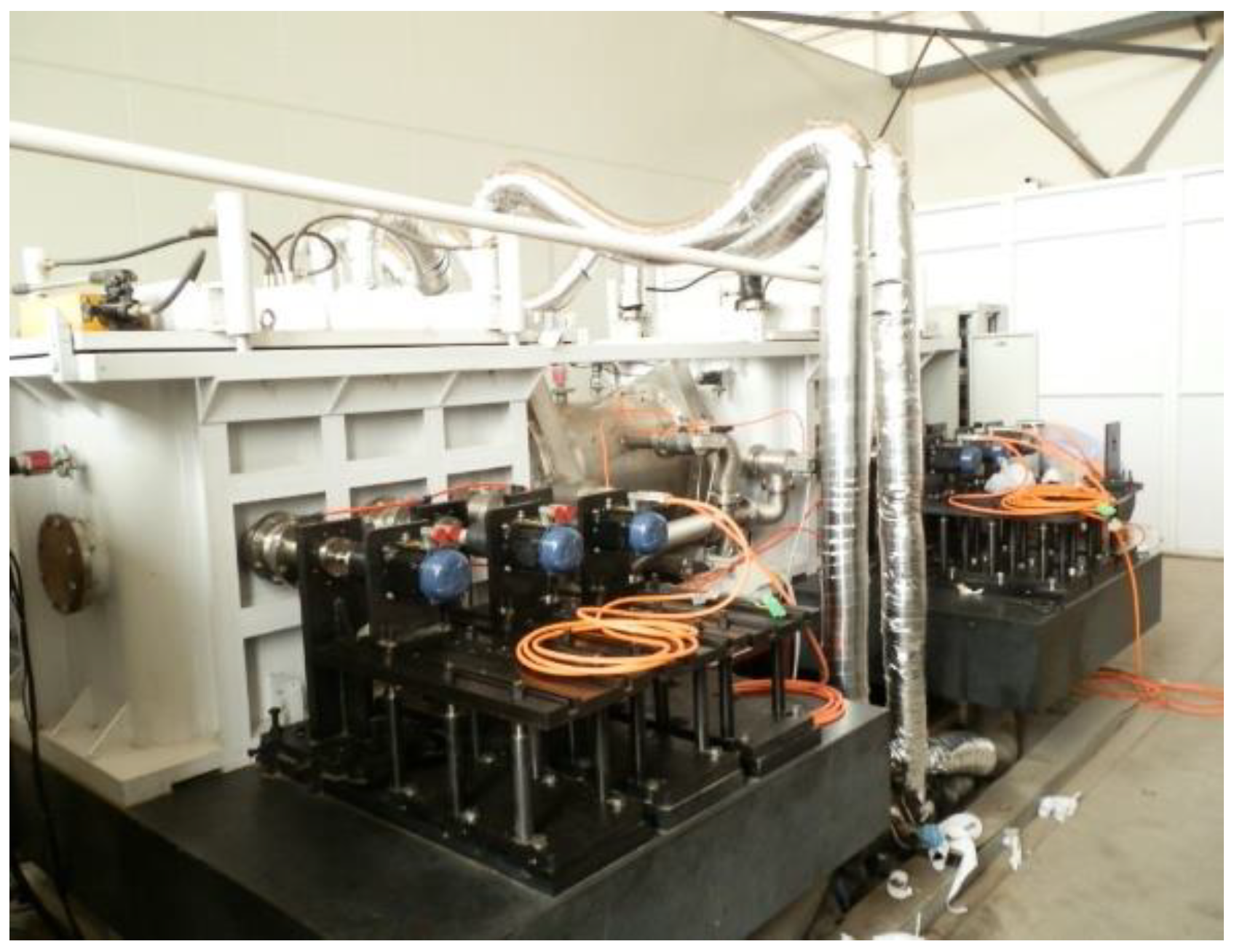
The equipment of the space harmonic reducer performance test system is shown in
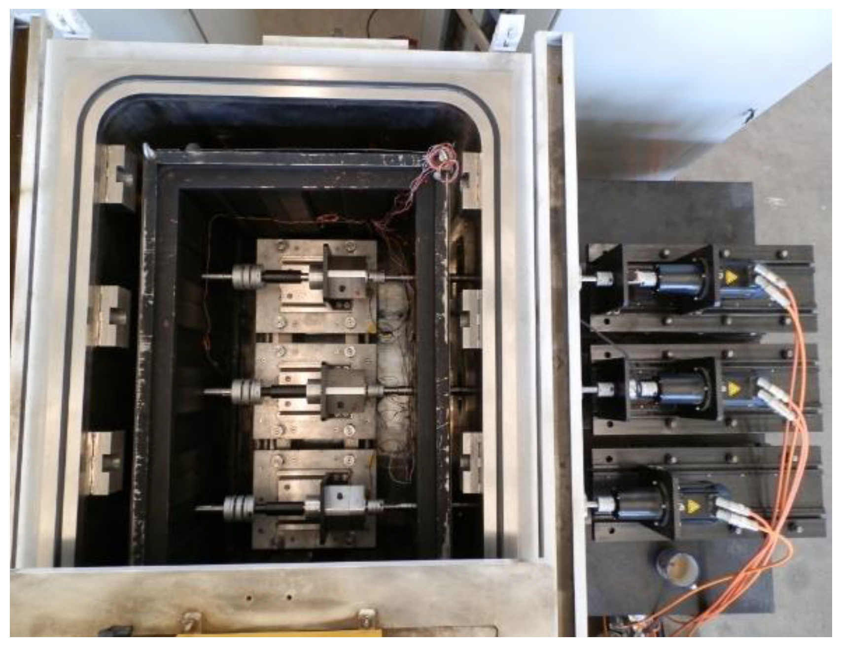
Figure 5, and the internal structure of the high vacuum and low temperature components is shown in
Figure 6. The high vacuum and low temperature test components include the magnetic fluid seal shaft at the input end, the vacuum tank, the optical platform fixed in the vacuum tank, the magnetic fluid seal shaft at the output end and the vacuum pumping system, the temperature guarantee system, the monitoring and control system, etc. There are two groups of high vacuum and low temperature components. Each group has a space harmonic reducer test mechanism inside and six motors outside. The parameters of the harmonic drive gear are as follows: model HD50-200, its deceleration ratio is 200:1, output speed is 1 r/min when input speed is 200 r/min, circular spline material is 40Cr, and flexspline material is 40CrNiMoA. The working conditions of the high vacuum and low temperature components are as follows: the space storage temperature is −180~+130 °C, the working temperature is −60~+85 °C, and the vacuum degree is 5 × 10
−5 Pa. For the working parameters, the output torque is 20 N·m, the input speed is adjustable from 3 rpm to 200 rpm, and the input pendulum angle is −120°~+120. In the harmonic reducer, the inner ring groove and outer ring groove of supporting bearings and flexible bearings, and the surfaces of flexspline and circular splines are lubricated by magnetron sputtering MoS2-based solid lubrication film. The bearing cages are made of PTFE-based self-lubricating composite materials. The magnetic powder brake is used to exert a torque of 5–20 N.m on the output shaft. The rigid wheel and the gear teeth of flexible wheel of the harmonic reducer was lubricated by DLC solid coating and PFPE vacuum grease.
In the space application, the load of the space harmonic reducer is so small that the flexsplines will not break in the ground application condition. Generally, the transmission efficiency is chosen as the criterion for the failure of the space harmonic reducer, and the accuracy is taken as the reference criterion.
In the specific test, take the “efficiency test” in the automatic performance test system of space harmonic reducer as an example. Firstly, select a motor in the test, and then select a certain operation mode in “constant speed constant moment” or “variable speed constant moment” or “constant speed variable moment”. Finally, the specific moment value is input for automatically run the efficiency test. During the testing process, the temperature range is from −40 °C to +85 °C, the low temperature vacuum degree is 5 × 10
−5 Pa and the high temperature vacuum is 2 × 10
−3 Pa. The temperature cycle is carried out at high temperature for six hours, low temperature for six hours and the temperature change rate of 3–5 °C/min. Data are collected every 200 h.
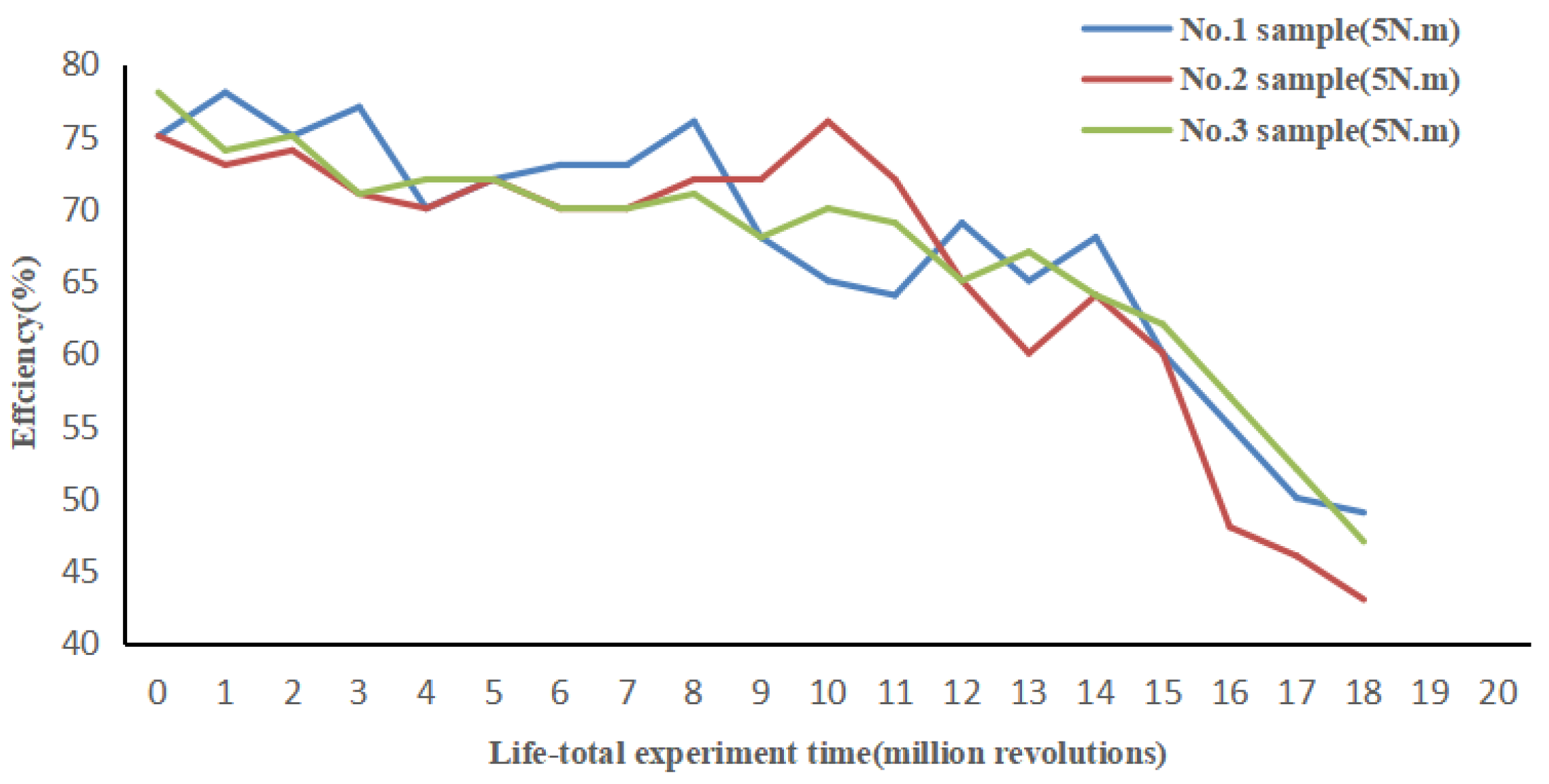
Figure 7 shows the efficiency test curve when the torque is 5 N.m. It can be seen that the transmission efficiency of the space harmonic reducer decreases with the increase of time. The trend of efficiency reduction became obvious in the 15th million revolutions, which was below 50%.
Similarly, when testing the transmission accuracy and backlash, input the rotation angle value, and set the rotation speed, then select the “continuous operation” or “swing” mode for testing. As
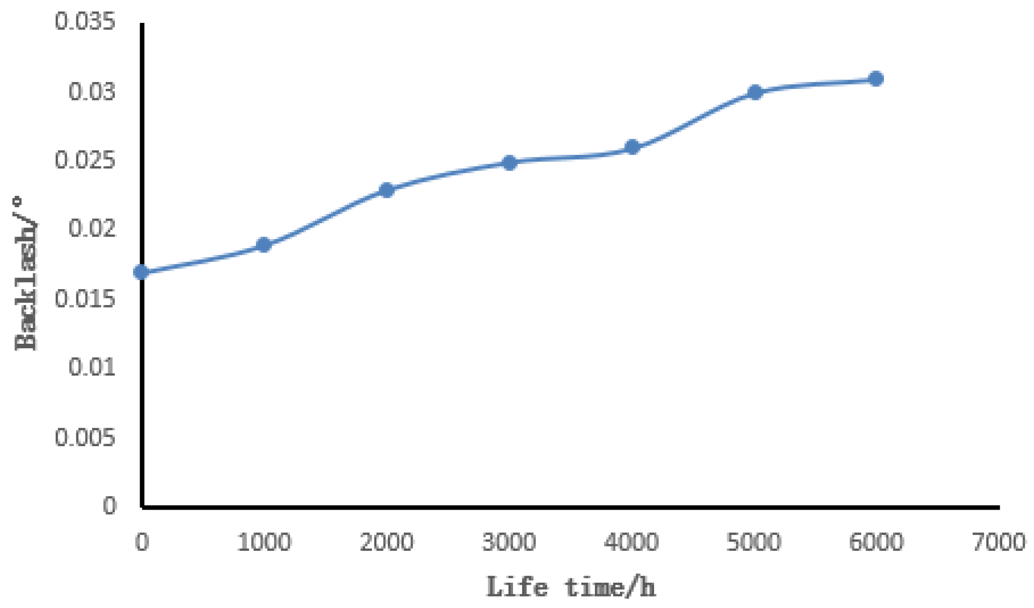
Figure 8 shows, with the increase of time, the transmission angle accuracy of the space harmonic reducer is increasing all the time. As
Figure 9 shows, with the increase of time, the backlash angle of the space harmonic reducer is also increasing all the time.
Figure 7 and
Figure 8 show that the transmission efficiency of the three harmonic reducer samples in the initial stage (the experimental stage from 0 r to 2.7 × 10
6 r) is relatively stable, while the transmission accuracy is between 0.02° and 0.022°, and it also remains relatively stable. However, it will have a slight increase, which is negligible for space applications.
Figure 9 shows that the hysteresis of the harmonic reducer increases from 0.017 to 0.027 at the initial stage of life, which is almost the same as the increase in transmission accuracy. The good performance of the transmission performance data in the initial stage is mainly due to the rigid wheel-flexible friction pair of the harmonic reducer at this stage, the inner wall of the flexible wheel-wave generator friction pair is in good lubrication state, the surface condition of the friction pair is measured well. There are also no abrasion excess particles between the friction pairs. As the test progresses, in the middle of the experiment (the experimental stage from 2.7 × 10
6 r to 5.4 × 10
6 r), the transmission efficiency, transmission accuracy, and hysteresis of the tested harmonic reducer are in a certain downward trend in the middle of the test, but the decline is within an acceptable range. This change does not affect the application of the space drive mechanism. As the test continues, in the later stage of the test, the transmission efficiency is in a rapid downward trend, which is mainly due to the wear of the teeth of the rigid wheel and the flexible wheel, the wear of the inner wall of the flexible wheel and the existence of excess wear particles between the friction pairs. These reasons lead to increased drive torque loss, which leads to a decrease in transmission efficiency.
The experiment proves that the automatic performance testing system of the space harmonic reducer developed in this paper can fully simulate the high and low temperature environment of vacuum for relevant testing, and accurately acquire the relevant performance parameters of the space harmonic reducer working in space. It provides a relevant test platform for further research and description of the transmission performance of harmonic drive system in space, and provides a test carrier for subsequent research of space lubrication coating materials.
5. Conclusions
At present, the life test of space aerospace products is mainly for component level and material level, but the whole machine and system level is seldom studied. Statistical analysis methods of life testing are complex, and the available data in engineering research are insufficient. Moreover, there is a certain gap between these methods and practical application of engineering. The establishment of a life test model and stress selection of aerospace mechanism products are often based on previous research experience and lack a theoretical basis.
In this paper, a test platform for simulating the performance of space harmonic reducer in vacuum environment is designed, which controls the Kolmogen motor as the driving motor through CANOpen bus interface, so as to collect real-time performance parameters such as angle and moment, and then to analyze and calculate the collected data to realize the test of transmission accuracy, backlash, and transmission efficiency of a harmonic reducer. The final test results show that the test automation can be fully realized in the high vacuum and low temperature test equipment without manual intervention, which provides experimental theory and technical guidance for the self-developed application of harmonic reducer in space, and also provides a test carrier for the subsequent research of space lubrication coating materials. This paper has the following works:
- (1)
The use of this test equipment has completed the life verification test of the space harmonic reducer under the vacuum high and low temperature simulation environment.
- (2)
The operating life of the harmonic reducer reaches 12 million revolutions, which can meet the 10-year use demand of the satellite antenna drive mechanism.
- (3)
The superiority of the solid-liquid composite lubrication method of DLC solid film-PFPE grease was verified, so that the harmonic reducer has a higher reliability in orbit under the condition of medium load (5 N.m) in space.
- (4)
The test equipment not only has the function of vacuum high and low temperature environment simulation, but also has the function of harmonic reducer variable load, “multiple sample number” and “multi-torque output conditions” simultaneous test functions, as well as advanced test technology, such as stable test and continuous on-line monitoring.
For the harmonic reducer for space, the main application problem is the insufficient operating life of the harmonic reducer under medium and high output torque load conditions (15–30% rated load), and under medium and high output torque conditions. In future, the wear rate of the friction working surface (the inner wall of the flexible wheel, the teeth of the rigid wheel and flexible wheel) will increase, and the follow-up research direction is mainly to study how to improve the wear resistance of the friction working surface, and to develop better lubricating materials and improve the service life of friction pairs.
For the harmonic reducer test and evaluation technology, it is necessary to further improve the transmission efficiency, accuracy, and return difference of the harmonic reducer, as well as the stability of the data during the life test. In addition, it is found that the test equipment can increase the number of test samples as much as possible to shorten the verification time of space lubricating materials and lubricating technology.


