Article

Machinery Foundations Dynamical Analysis: A Case Study on Reciprocating Compressor Foundation

by
Stefano Giorgetti
1,
Alessandro Giorgetti
2,*,
Reza Tavafoghi Jahromi
1 and
Gabriele Arcidiacono
2
1
Baker Hughes–Nuovo Pignone, 50127 Florence, Italy
2
Department of Engineering Science, Guglielmo Marconi University, 00193 Rome, Italy
*
Author to whom correspondence should be addressed.
Machines 2021, 9(10), 228; https://doi.org/10.3390/machines9100228
Submission received: 6 September 2021 / Revised: 30 September 2021 / Accepted: 1 October 2021 / Published: 7 October 2021
(This article belongs to the Section Machine Design and Theory)

Abstract

:
A faulty dynamical interaction between a machine and a foundation can lead to unexpected and dangerous failures, impacting human lives and the environment. Some machines, as reciprocating compressors, have a low rotation speed; this can lead to dangerous frequency for the foundation blocks. For this reason, a careful analysis shall be done during the design phase to avoid the range of the frequency of resonances and low vibration speeds. Designers can approach this problem by relying both on Analytical Theory and Finite Element Analysis. This article compares these methods by studying the dynamical response of different foundation geometries in a case study of a reciprocating compressor foundation. The applicability limits of Analytical theory are explored and an evaluation of the difference in the estimation of natural frequencies of the system using Analytical Theory and Finite Elements Analysis are made for different foundation geometries. The comparison shows similar results until the foundation geometry is rigid; reference geometries limits are provided so that designers can choose which of the methods better suits their type of analysis.

1. Introduction

Compressors play a fundamental role in industrial plants, where they are given the task of compressing the fluid, and pushing and pressing gasses in piping lines, in vessels and inside the Balance of Plant of the machine. In particular, a reciprocating compressor design requires high accuracy as fluid pressures during operational work are very high. Several analyses of piping and machine under high pressures are needed to achieve an accurate design [1].
Plants must be efficient, meaning they must ensure performance and reliability for a long time by minimizing their maintenance costs [2,3].
The engineering practice in foundation design is widely aware of the vibration problems caused by the critical resonance that comes from operational loads of the mechanical system.
If not properly checked, the foundation behavior in terms of vibration and frequency is both a performance-related problem and a human and machine safety one.
Unexpected failures due to resonance vibration, the machine’s proximity to vessels under pressure, and leaks from process pipes can result in severe consequences for man and the environment; a safe environment must always be guaranteed for the machine.
Generally, foundations are classified into three categories: shallow, deep, or a combination of both. For this article, only shallow foundations are considered.
Many different types of dynamical loads, such as the seismic and machinery ones, can load foundations. Depending on the type of load, different types of solutions have been developed [4,5,6,7,8,9].
In this article, only machinery loads are considered.
Machinery loads can be analyzed by analytical or numerical approaches in the current engineering practice, such as Barkan’s Theory [4] and Finite Element Analysis (FEA).
Barkan’s theory is a methodology where the shallow foundation block is considered a rigid body resting on an elastic half-space, which is the soil. This approach allows designers to obtain dynamical responses such as critical frequencies and maximum displacements of the foundation.
Barkan fits into Western academia, validating the dynamical theories by experience and supplying equations for the dynamical calculation. Thanks to Barkan [4], it was possible to face the dynamic behavior of block type foundations subjected to the dynamical and impact loads, providing a significant contribution to fundamental laws and equations for dynamic analysis supported by all types of terrain.
The modern theories on dynamical analysis begin with G. Gazetas. Gazetas reaffirms some fundamental concepts: the circular foundation rests on half elastic soil [10], the equations for motion and stiffness [11,12,13,14,15]. He demonstrates how to use data to estimate the translational and rotational motions of foundations and to obtain dynamic stiffness and damping parameters for the soil springs. The modern theory of this model confirms Barkan’s hypotheses that he had used for the same type of modelling.
As will be shown in the following paragraphs, in this work, the authors used Barkan’s analytical model and Gazetas’ one; since this last one developed from the first one, when using Barkan’s Theory term, both of the analytical methods will be meant.
However, it remains to be discovered where and for which geometries the body loses its stiffness and when the described analytical method fails.
Rigid body theory allows for greater sensitivity in the analysis of the results but requires a slower calculation process.
Another common approach to solving the dynamical study of foundations is the numerical approach [15,16,17,18] and, in particular, the Finite Element Method (FEM). The FEM analysis is more accurate in managing a large amount of detailed geometrical data and in this paper, we consider this result as the reference. On the other hand, the use of FEM is a more time-consuming process during the preliminary design phase and can introduce a loss of awareness of the results by the designer.
A conceptual comparison between these two methods exists in the literature, but the authors found no comparison to help understand their convergence and divergence in real applications.
This paper aims to compare Barkan’s rigid body theory and the FEM approach. In this way, it is possible to understand how these two methods converge to similar solutions and when they produce diverging results.
In particular, a case study about the foundation of a reciprocating compressor is presented, and different foundation blocks are used to compare the results of the two approaches. Different foundation blocks have been selected.
The following paragraphs show:
  • Section 2: Materials and methods, Barkan’s rigid body analytical calculation, FEM and dynamic soil analysis;
  • Section 3: Case study, the considered geometry and inputs are described;
  • Section 4: Results and discussion, the original geometry of the foundation is reduced and the results of the different analyses are discussed;
  • Section 5: Conclusion, the main results are summarized, and future developments of the topic are introduced.

2. Materials and Methods

In this work, the flowchart shown in Figure 1 has been followed. The starting input data are the foundation geometry and the dynamical soil parameters. Two analyses are made, respectively, based on Barkan’s theory and FEA. Their results are then compared, and the approach is repeated for the reduction of the foundation geometry.
Both Barkan’s and FE methods are introduced in the following paragraphs. Using these analyses makes it possible to identify the modal response of the total system composed by machine, foundation, and soil. Since these methods need the definition of the soil parameters, the choice of the dynamical properties of soil used in these analyses are described.

2.1. Barkan’s Rigid Body Analytical Calculation Method

In his book, “Dynamic of bases and Foundation” [4], Barkan introduces fundamental formulas based on hundreds of measurement campaigns of foundations under dynamical loads. The approach is useful for identifying the modal analysis of a rigid body, and it is still an essential reference for the vibrational theory of the foundation blocks of the machines.
Barkan’s theory is based on the following main concepts:
-
the foundation block is considered a rigid body;
-
the soil is modelled as a spring and can be summarized with a rotational and translational degree of freedom referred to as an orthonormal reference system jointed to the body;
-
under dynamical loads, there is a linear relationship between foundation block displacement and soil reaction and between vibration amplitude and exciting force. The soil is assumed as a bed of springs with stiffness expressed by the elastic coefficients of compression and shear;
-
the vibrational response of the system composed of the machine, foundation and soil under the dynamical load is in frequency with the load applied;
-
the dynamical soil response is assumed to be a mass-spring viscous damper system;
-
the soil under the foundation has no inertial properties but only elastic properties.
Based on the above assumptions, Barkan’s theory describes the foundation vibration under the exciting load. Vibration is expressed by the foundation natural frequency fnz and the machine pulsation ω.
Once the appropriate soil damping coefficients are assumed, vibration amplitudes along the several frequencies are found.
Regarding the soil modelling, Barkan considers it a semi-infinite elastic solid and establishes a linear relationship between the soil reacting on a vibrating foundation and the displacement on the foundation. Thanks to his direct experiences in several campaigns, he built the relationship between the displacement and the reaction in terms of the coefficients of elastic uniform and nonuniform compression and the coefficient of elastic shear. In addition, in his principle, the soil is assumed to have only elastic properties and lacks properties of inertia; instead, the machinery foundation is considered to have inertia properties and lacks elastic properties.
These assumptions about the soil and the foundation make it possible to analyze foundation vibrations such as the problem of a solid body resting on weightless springs, with the latter working as a model for the soil.
The analysis of dynamically loaded foundations is performed, considering the rectangular foundation as a circular foundation with equivalent properties; then, three translation springs and three rotational springs (which summarize the elastic soil properties) are placed under the foundation in the centroid of the resting soil area.
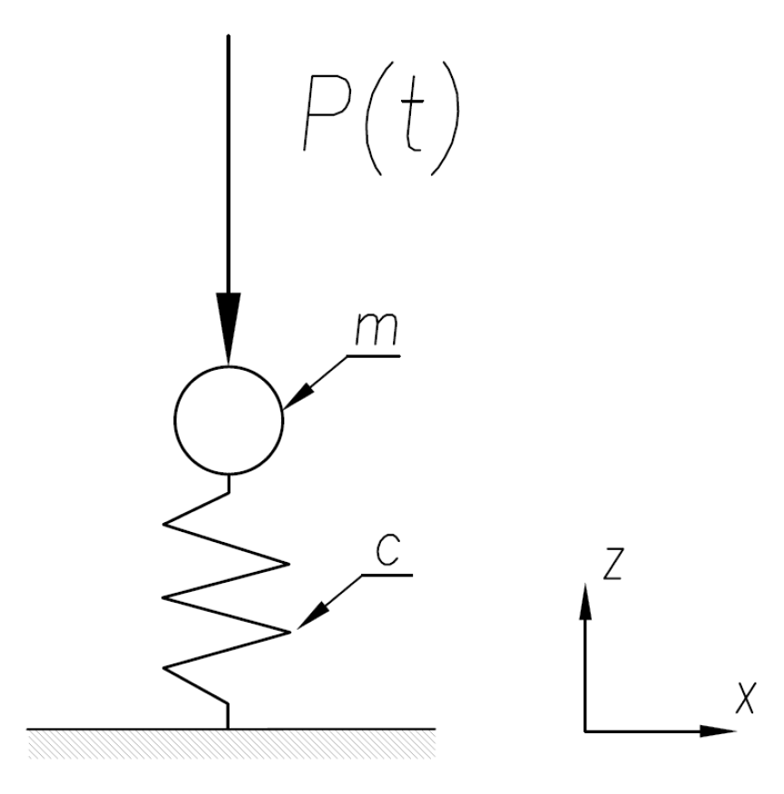
The case where the exciting force P(t) is a harmonic function of time is considered, where ω is the exciter pulsation. This corresponds to the case of the rotating machine, where machines impose exciting loads as a harmonic function of the time.
P ( t ) = p · sin ω t .
The exciting force P(t) is vertical and changes in time. Let us assume that the center of mass of the foundation and machine and the centroid of the foundation area, in contact with the soil, lie on a vertical line that coincides with the direction of action of the exciting force P(t). In this case, the foundation will undergo only vertical vibrations. Since the foundation is assumed to be a rigid body, its displacement is determined by the displacement of its center of gravity. The soil can be modelled with a weightless spring (where c expresses the rigidity of the base and m the mass of the foundation).
In this way, the problem of vertical vibrations of a foundation can be reduced to the analysis of the vibrations of a centered mass resting on a spring, schematized like in Figure 2 below:
Barkan uses this motion equation describing a harmonic force that changes during the time, inserting t as a variable of the time (s) and the constants ω for the machine pulsation (in rad/s), and p as a specific exciting force.
The exciting specific force is obtained by:
p =   P m ,
where P is the exciting force and m is the mass of the foundation.
Barkan analyses the motion of the system using D’Alambert’s equilibrium principle.
Considering the vertical axis z and applying the exciting force to the system, the rigid body moves along the axis with the displacement z, the velocity z   ˙ and the acceleration z ¨ .
The motion equation (damped rigid body with exciting harmonic force) can be expressed by:
z ¨ + 2 c z ˙ + f n z 2 · z = p sin ω   t ,
where c = damping constant (soil stiffness, i.e., coefficient of the rigidity of the base), and f n z = natural frequency of the system, along the z-direction.
The solution of this equation, corresponding only to the steady forced vibrations of foundations, is:
z = A z * sin ( ω t γ ) ,
where A z * = the amplitude of forced vibration, γ = phase shift between exciting force and displacement induced by this force and z expresses the displacement value (i.e., the range of the vibration amplitude starting from z = A z * with sinusoidal variation law) that depends on the vibrational amplitude.
The solution of the differential equation gives the displacement and this solution is a frequency response, and a delay due to the damping factor force and hence the displacement induced by this force is given in the Equation (5).
tan γ = 2 c ω f n z 2 ω 2 .
The damping of soil is a fundamental parameter connected to soil characteristics. The damping reaction of the soil on the amplitude of free vibrations of a foundation is impactful, even for small values of c.
c is called the damping constant; two times its value equals the coefficient of resistance α per unit of foundation mass (6).
c = α 2 m .
So, it is possible to express the amplitude of forced vibration A z * by the following formula:
A z * = P m ( f n z 2 ω 2 ) 2 + 4   c 2 ω 2
This equation allows the understanding of how much a load is amplified to obtain the maximum displacement corresponding to an identified frequency.
The Barkan’s analytical theory for the foundation dynamical analysis reduces the rectangular resting base to a circular base resting on a semi-infinite elastic soil (Figure 3); according to this geometry, it is possible to solve the differential equation with the analytical computation.
With this information, it is possible to evaluate the following parameters:
Vertical   Translation    R v = l x · l y π
Horizontal   Translation R h = l x · l y π
Rotation   around   x -axis R x x = ( l x · l y ) 3 3 π 4
Rotation   around   y -axis R y y = ( l y · l x ) 3 3 π 4
Rotation   around   z -axis R z z = l x · l y ( l x 2 + l y 2 ) 3 6 π 4 .
The equations relevant to the translation motion (Vertical and Horizontal) have the same contact area l x · l y because the foundation moves on the soil depending on its surface that is in contact with the soil area; thus, R v and R h are expressed by the same equation.
Based on the horizontal contact area of the foundation, soil elasticity and rigidity and mass of foundation, Barkan identifies the natural frequency of the system according to the following law:
f n z 2 = c r m = c u · A m .
It establishes a fundamental relationship that joins the K stiffness value with soil coefficients and horizontal contact area.
K = c u · A ,
where c u is the coefficient of elastic uniform compression of the soil and c r is the coefficient of rigidity of the base.
In this work, since a rectangular foundation is studied and in situ soil parameters are assumed, Dobry and Gazetas [9] expressions are more appropriate for this case. These expressions are derived from Barkan’s Theory. Usually, other used expressions impose the transformation of a rectangular shaped foundation into a circular one by means of equivalent radius calculation.
Dobry and Gazetas expressions, referring to a foundation block embedded in an elastic half-space, are the following:
K x = k x · K x = k x · ( K y 0.21 · L · G 0.75 μ · ( 1 B L ) ) · ( 1 + 0.15 D B ) · [ 1 + 0.52 ( h B A w L 2 ) 0.4 ]
K y = k y · K y = k y · S y 2 · L · G 2 μ · ( 1 + 0.15 D B ) · [ 1 + 0.52 ( h B A w L 2 ) 0.4 ]
K z = k z · K z = k z · S z 2 · L · G 1 μ · [ 1 + 1 21 D B ( 1 + 1.3 A b 4 L 2 ) ] · [ 1 + 0.2 ( A w A b ) 2 / 3 ]
K r x = k r x · K r x = k r x · S r x G 1 μ · ( I r x ) 0.75 · ( L B ) 0.25 · { 1 + 1.26 d B [ 1 + d B ( d D ) 0.2 B L ] }
K r y = k r y · K r y = k r y · S r y G 1 μ · ( I r x ) 0.75 { 1 + 0.92 ( d L ) 0.6 [ 1.5 + ( d L ) 1.9 ( d D ) 0.6 ] }
K r z = k r z · K r z = k r z · S r z · G · ( J ) 0.75 · [ 1 + 1.4 ( 1 + B L ) ( d B ) 0.9 ] ,
where:
  • G′ dynamic shear modulus;
  • µ Poisson modulus;
  • L, B the semi-length and the semi-width of the base rectangle of foundation;
  • D embedment depth;
  • d height of foundation lateral surface in contact with the soil (dD);
  • Aw area of foundation lateral surface in contact with the soil;
  • Ab area of the rectangular surface of the foundation base in contact with soil;
  • S i ,   S r i dimensionless parameters depending to the soil typology
  • K i static stiffness values;
  • ki stiffness coefficients for the calculation of dynamic stiffness values; they are a function of L, B, D, μ , where the- dimensionless amplitude is expressed by means ratio
    a 0 = ω B V s 2 ,
    where Vs shear waves speed in the ground.

2.2. Finite Element Method

The typical model with its main elements can be found in Figure 4. The software used for the Finite Element Analysis is SAP2000 ©.
The foundation block is modelled by using solid elements. The solid elements constitutive law is elastic linear, and the material is C25/30 concrete. Its properties are: mass, 2.55 [KN/m3], modulus of elasticity 31.5 [GN/m2], Poisson 0.2, shear modulus 13.1 [GN/m2] and strength 25 [MN/m2]. The maximum size of the solid element is 25 × 25 × 25 [cm].
The machine is modelled by inserting a point corresponding to its Center of Gravity (C.O.G.) that contains its weight. The machine COG is connected to the foundation block by means of rigid links and ending in the anchor bolts positions.
As will be shown in the next paragraphs, the stiffnesses of the springs under the foundation are estimated using Barkan’s theory, whose equations were shown in previous paragraphs (Equations (15)–(20)). Since the values obtained with the analytical methods are referred to concentrated stiffnesses, they have been distributed on the bottom surface of the foundation block and the reason for this choice will be shown in the next paragraph.

2.3. The Soil Model and the Dynamical Analysis

Let us consider a machine installed and connected on a foundation block through anchor bolts; the foundation rests on a soil considered elastic. Barkan’s theory reduces this system to a mass resting on a spring with an exciting force P(t), while the FEM model reduces this system to a machine supported on the block by rigid links and considers the foundation block resting on a bed of spring. These models can be seen in Figure 5.
The soil is considered as an elastic semi-infinite solid (usually the considered soil starts from 1–2 m below the grade). Two fundamental parameters characterize the soil response: stiffness (k) and damping (c). In the paper, we use the Bowel’s [5] approach to obtain these parameters. Barkan used vibrodyne and plate bearing tests to obtain the elasticity factor for each type of substratum. And Bowel provided the frequency dimensionless a 0 the value referred to the circular base (radius r 0 ).
a 0 = ω r 0 ρ G ,
where the velocity of the shear wave V s is expressed by:
V s = G ρ
and
  • ρ  is soil density;
  • G’ is the dynamic shear module;
  • ω is the pulsation of excitement;
  • a 0 can be used for rectangular bases with the following expression:
    a 0 = ω B V s
    the key value to identify the frequency is the V s through the pulsation ω and the dimension B of the circular base; V s is the velocity of the propagation of the waves, which is directly linked to the shear module G.
To understand how the soil replies to a dynamical excitation, it is necessary to know each parameter’s different contribution that defines the mechanical property. These parameters are the density, the Poisson’s ratio, the specific weight, and the shear wave propagation velocity.
The dynamical shear module can be obtained by:
G = ρ V s 2 .
The propagation of the shear wave provides how the sound energy propagates through the dept of the ground. The impulsive effect coming from the harmonic forces is transferred as energy through and along the foundation body to the underground soil.
One of the most serious difficulties in vibration analysis is determining the necessary soil values of shear modulus G′ and Poisson’s ratio μ as the differential equation solution inputs. It is important to choose a shear module value to reach an accurate dynamical response of the foundation, corresponding as much as possible to the real response of the system. Direct measurements of the wave velocity at the different dept to the soil let extrapolate an average value useful for identifying the right G.
Direct measurement can be Standard Penetration Test (SPT), an in-situ standard penetration Test that deduces the V s by the impact of the blows from a slide hammer with a predefined mass; instead of SPT a more precise analysis can be made with Down or Cross Hole ASTM D7400 and D4428, where the V s is measured directly.
Based on SPT tests, correlations (of the type: SPT N → Vs or SPT N → G0) enable calculating the expected dynamic soil shear modulus [19,20].
The values obtained can be compared to the values obtained through the Down Hole test (DH) to assess the reliability of the DH test itself that, if correctly executed, is the preferred method for estimating the small strain shear properties (Figure 6 is an example of a general DH test result).
As an example, in the below graph, G0 values collected by a soil investigation campaign are summarized. Boreholes (BH) are placed in different positions under the foundation resting area during the soil investigation, so different N values are found along their depths during the pits beat. Through the transfer formulas given in the literature, it is possible to summarize, at different soil depths, the G0 values. An affirmed literature [19] provides equations and formulas to correctly identify the V s values. These formula changes depend on the soil typology, which can change along with the depth.
The VS-stress equations generally follow the form of the equation:
V s = a · N 60 b · σ v c ,
where
  • a = numeric coefficient;
  • N 60 b = SPT N-value is a uniform reference energy ratio of 60% of the theoretical SPT energy (N60);
  • Q = quaternary age;
  • σ v c is the total and effective stress.
Finally, the designer shall interpolate the values of G0 depending on the soil depth considered under the foundation block.

3. Case Study on Reciprocating Compressor Foundations

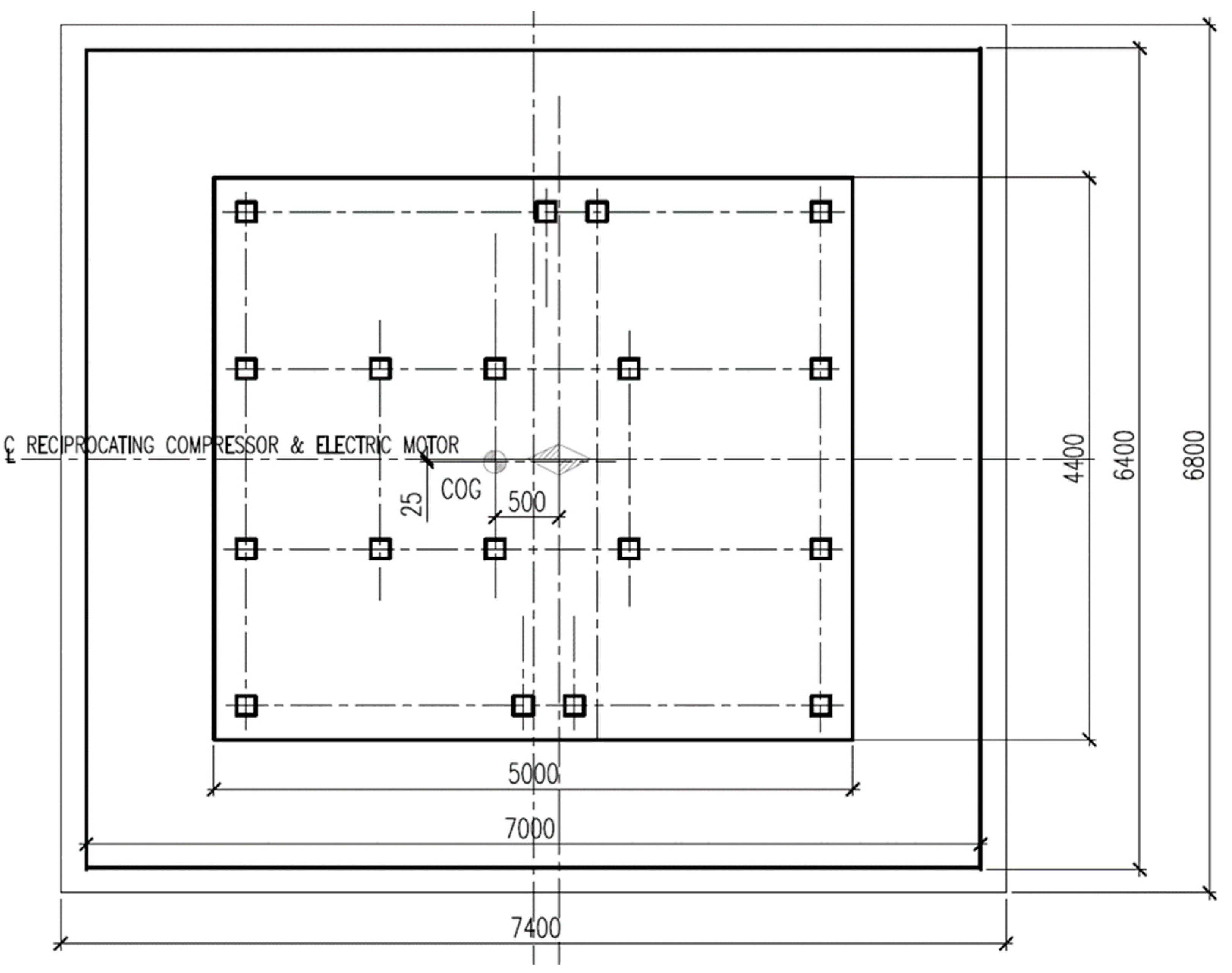
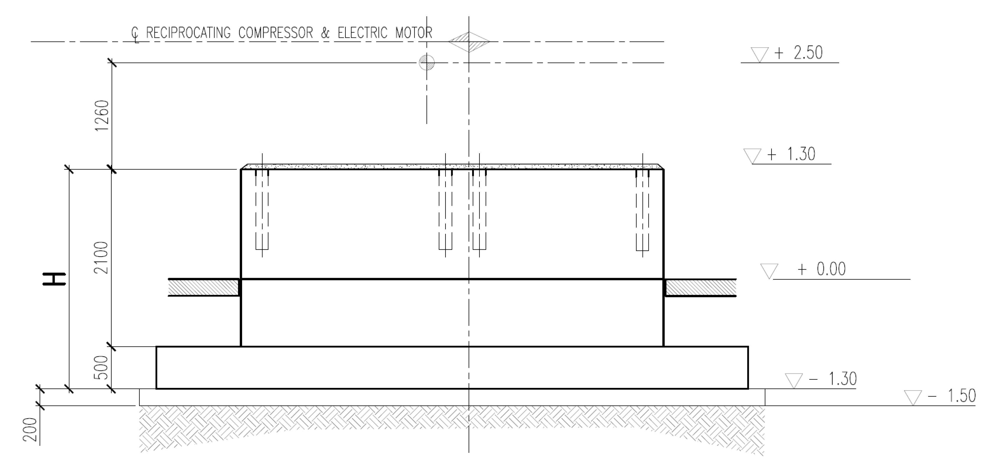
The original geometry of the foundation block studied in this article can be found with details in Figure 7 and Figure 8.
The short sides of the foundations are considered the dimension relevant to the solid body without base elongations because the block can be considered a rigid body without these protrusions. So, L = 4400 [mm] is the length of the short side.
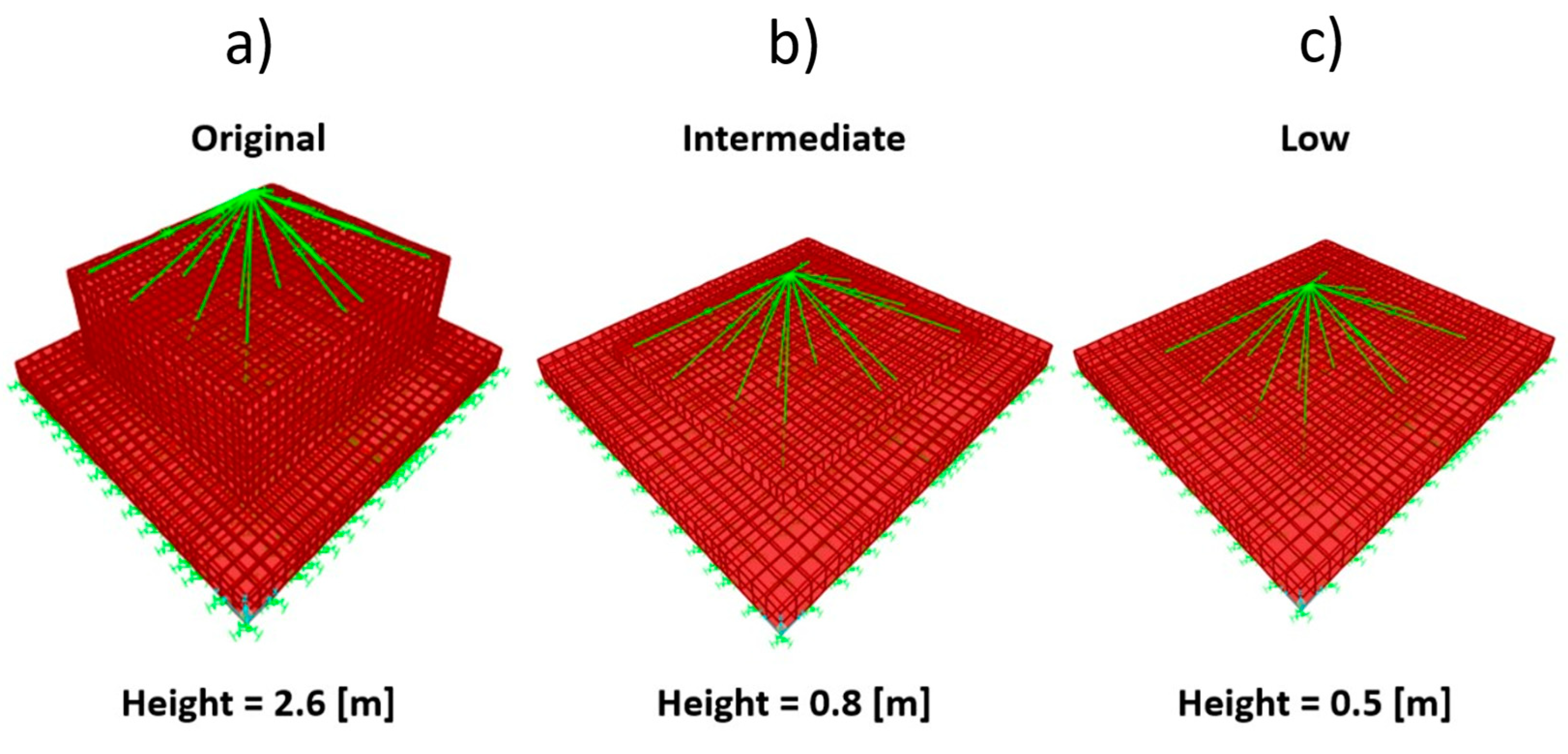
The structure was modelled using the geometry provided in Figure 7 and Figure 8 and by means of solid elements as shown in Figure 9.
In particular, three different heights H (Original case H = 2.6 m, Intermediate case H = 0.8 m and Low case H = 0.5 m) have been considered to evaluate the results of the two methods with different stiffnesses of the system.
The adopted soil model for dynamic analysis is based on three homogeneous soil layers with constant elastic properties. These are obtained with the DH test rather than with the SPT empirical correlations, as shown in Table 1 and Figure 6. The different soil parameters change along with the depth of each Borehole (BH); the choice of the adopted G is an interpolation between the measured values.
The soil has in-homogeneous properties but is possible to select common elastic characteristics along with its depth. As an example, in the Vs value collected in Figure 6, three homogeneous layers can be identified (Figure 10), in our case with the following soil parameters:

4. Results and Discussion

Finite Element Models have been developed to validate the results obtained by Barkan’s theory. Due to the higher accuracy brought by FEA, its values will be considered the reference ones when calculating the error between the analytical theory. The comparison has been made in terms of modal shapes and respective frequencies. Three models with smaller geometries of the foundation block were analyzed to investigate the validity and differences with Barkan’s theory.

4.1. 1st Model—Original Height

The starting analysis was made based on the original geometry previously shown (Figure 9a). Using Barkan’s theory, system stiffnesses are:
-
Translational vertical stiffness, Kv, 3467.62 [MN/m]
-
Translational horizontal stiffness, Kh, 3379.93 [MN/m]
-
Rotational stiffness about x-axis, Kxx, 45,378.46 [MNm/rad]
-
Rotational stiffness about y-axis, Kyy, 51,365.58 [MNm/rad]
-
Rotational stiffness about z-axis, Kzz, 78,317.45 [MNm/rad]
These stiffnesses were distributed on the bottom surface utilizing spring elements concentrated in solid elements nodes. Table 2 shows a comparison between the natural frequencies of each movement found by Barkan’s theory and those obtained by linear FEM.
FEA and Analytic methods are compared in percentages as:
F r q u e n c y   d e v i a t i o n   [ % ] = f F E A     f B k     f B k   × 100 .
In Figure 11, the first six modal shapes obtained from FEA are shown.

4.2. 2nd Model—Intermediate Height

The following analysis is made by reducing the original geometry; the total height of the block was modified to 800 mm. Figure 9b shows the geometry used in this case.
Using Barkan’s theory, systems stiffnesses for this case are:
-
Translational vertical stiffness, Kv, 3277.93 [MN/m]
-
Translational horizontal stiffness, Kh, 3205.79 [MN/m]
-
Rotational stiffness about x-axis, Kxx, 44,023.98 [MNm/rad]
-
Rotational stiffness about y-axis, Kyy, 49,788.52 [MNm/rad]
-
Rotational stiffness about z-axis, Kzz, 78,317.45 [MNm/rad]
Table 3 shows the same comparison between the natural frequencies of each movement found in Barkan’s theory and those obtained by linear FEA for the intermediate case.

4.3. 3rd Model—Low Height

The final analysis was made by reducing the original geometry and considering only the concrete slab that is 500 [mm] tall. Figure 9c shows the modified geometry. Using Barkan’s theory, systems stiffnesses for this case are:
-
Translational vertical stiffness, Kv, 3159.59 [MN/m]
-
Translational horizontal stiffness, Kh, 3078.89 [MN/m]
-
Rotational stiffness about x-axis, Kxx, 442,860.12 [MNm/rad]
-
Rotational stiffness about y-axis, Kyy, 48,440.19 [MNm/rad]
-
Rotational stiffness about z-axis, Kzz, 78,317.45 [MNm/rad]
Table 4 shows the comparison for the low case.

4.4. Discussion

To give an overview of the differences between Barkan’s theory and FEA as the geometry changes, Table 5 summarizes the obtained results: FEA and Analytic methods.
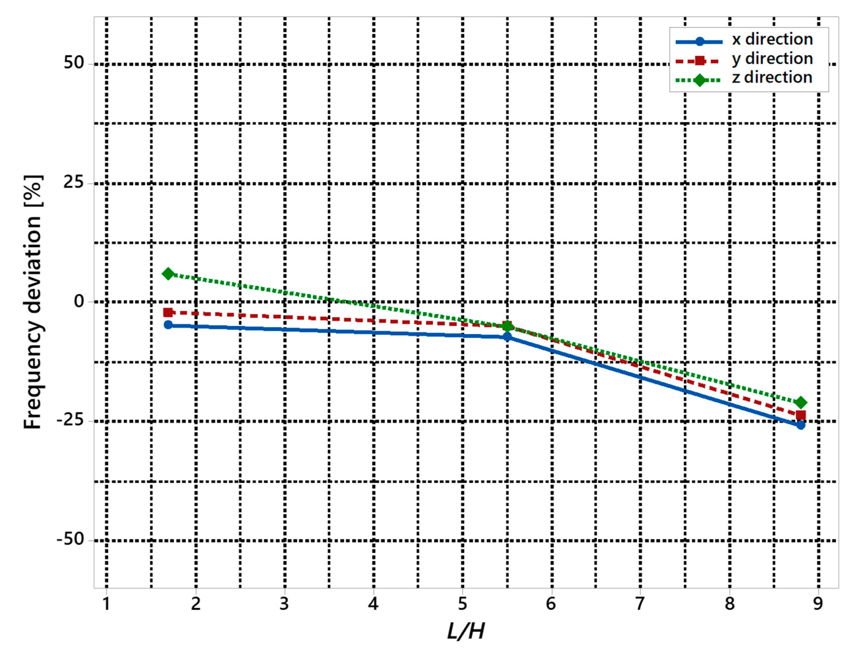
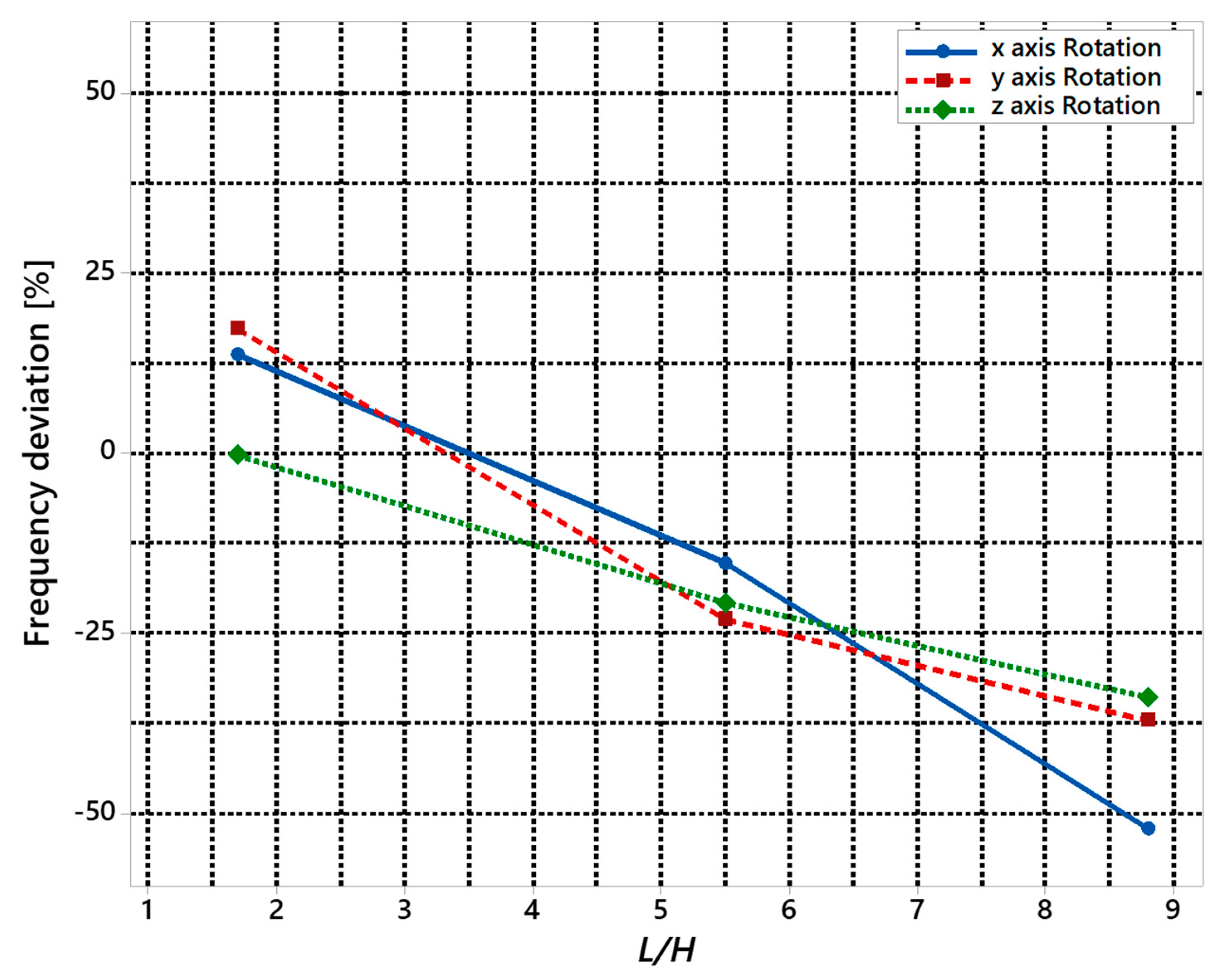
Two diagrams have been developed to visualize these results, one showing the Frequency deviation of the translation degree of freedom and one of the rotation ones (Figure 12 and Figure 13). The x represents the ratio between L/H, where L is the foundation width (short side) and H its height, while y represents the Frequency deviation between the frequency found between FEA and analytical methods.
It is possible to see different behavior between translational and rotational frequencies: for the first ones, smaller values of differences are achieved, while for the second ones, bigger values are obtained even for the original rigid geometry. It is possible to observe that the rotational frequencies are more distant from each other than the translational ones. As shown in the original case, the modal shapes remain the same as the geometry changes (i.e., both translational and rotational ones, as shown in Figure 11), but the discrepancy in the rotational frequency reaches higher values than in translational ones.
By analyzing the data obtained, it is possible to define a way of using the analytical data that can enable fast but at the same time safe evaluations.
The data obtained from the analytical approach can then be used, taking into account a maximum margin of error.
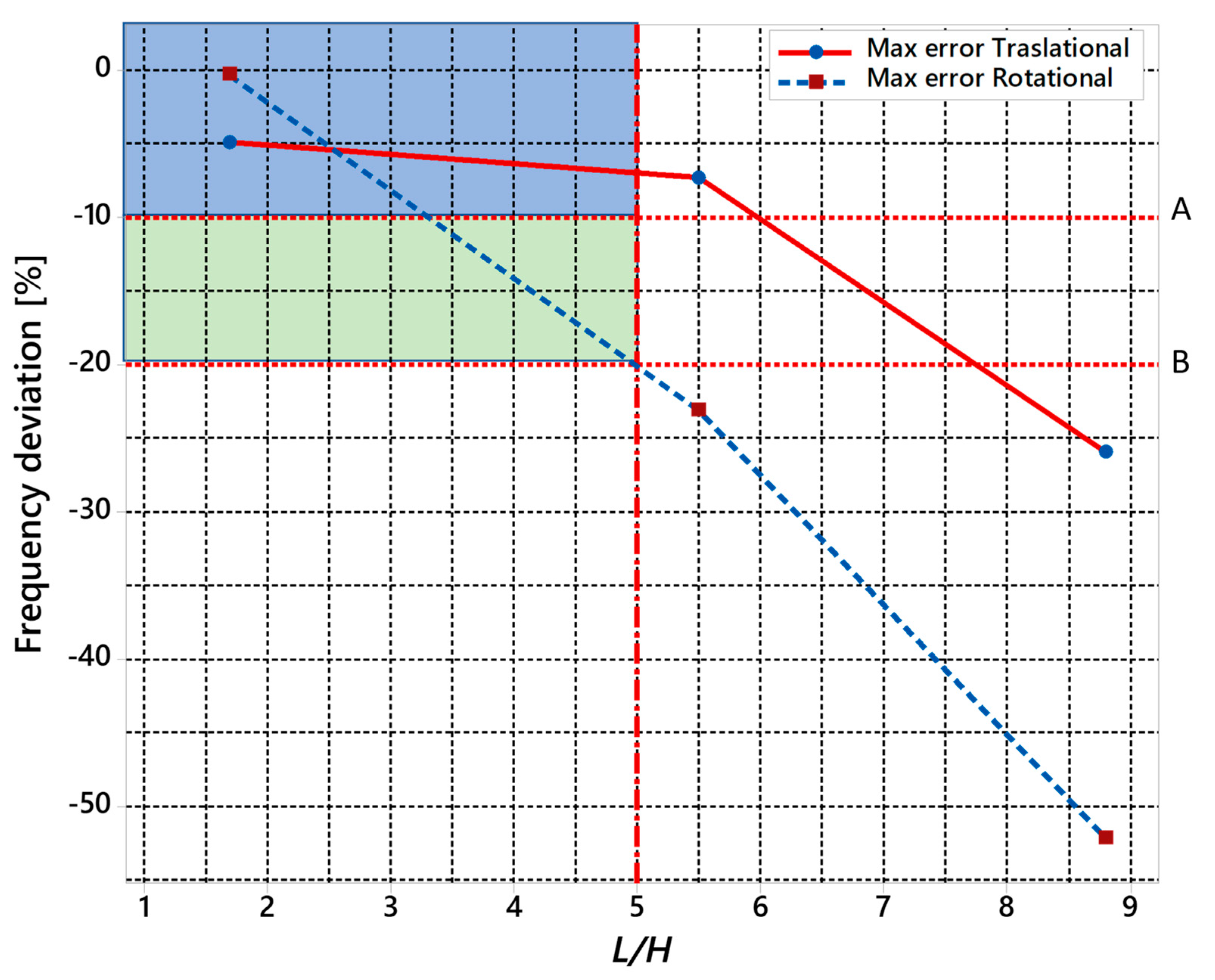
This margin of error, by comparison with the data obtained from the FEM analysis, can be identified as −10% (Figure 14 line A) for the frequencies of translational modes and −20% (Figure 14 line B) for the frequencies of rotational modes as long as the L/H ratio remains below 5. Beyond this dimension ratio, the rigid body theory appears to lose an acceptable level of accuracy.
Usually, the type of machines considered in this work (reciprocating compressor) work at an operating velocity in the range 200–900 rpm (and therefore with steady-state frequencies in the order of 5–15 Hz). For this reason, the low resonance frequencies are the most critical and the higher uncertainty of rotational modes can be considered acceptable as they are not critical due to the higher resonance frequencies.

5. Conclusions

Some machines, such as reciprocating compressors, have a low rotation speed and this can be dangerous for the foundation blocks; a careful analysis must be made during the design phase to avoid the resonant frequency range overlapping with the operating speed.
Nowadays, it is common to perform dynamic calculations using FEA for designing foundations; on the other hand, this article shows how analytical methods should still be used as a reference.
The former is a quick method and is useful in the conceptual design phase of the block at the beginning of the project, in particular considering that the design of the foundation usually starts after the definition of the machine and its auxiliaries, which strongly constrains the L dimension of the system. This analytical approach permits a fast and better alignment of the various constraints during the initial design phase. After these detailed design phases, the geometry can be dynamically checked with a more comprehensive FEA analysis.
In fact, as good engineering practice, it is important to balance both calculation methods during the product development process. As a result of this work, the designer can use the two methods with more awareness of the effects of each design parameter.
In particular, this paper shows that using an analytical approach ensures acceptable results if the rigid body hypothesis is applicable but differs progressively from FEA when the foundation block becomes less rigid. Based on the case study presented in this paper, this scenario happens when the ratio L/H (minor length of the foundation base vs. block height) is more than five and considers a maximum overestimate in translational resonance frequencies of 10% and rotational frequencies of 20%. Beyond this L/H ratio, the rigid body theory appears to be too difficult to be used for reliable estimation.
Possible future developments of the topics introduced by this paper are:
-
evaluate the response of the system resting on an elastic soil model as per the Winkler bed model, obtaining different responses to compare;
-
calculate the amplification factor based on FEA and Barkan analysis and identify the displacement of the system comparing with the specification limits;
-
identify the difference between results from FEA and Barkan analysis, changing geometries;
-
model the soil, differentiating for each stratum different bed springs and analyzing the dynamical response with FEM;
-
model the machine and soil with stiffeners and differentiating for each stratum different bed spring, and analyzing the dynamical response with FEM;
-
model each component of the machine with appropriate stiffeners, analyze the model of the system machine, foundation and soil, calculating the response;
-
model the soil with a nonlinear spring and calculate the dynamical response to further develop the topics covered.

Author Contributions

Conceptualization, S.G., A.G.; methodology, A.G., R.T.J.; formal analysis, S.G., R.T.J.; data curation, S.G., A.G.; writing original draft, S.G.; R.T.J., A.G.; writing review & editing, A.G., G.A.; supervision, G.A. All authors have read and agreed to the published version of the manuscript.

Funding

This research received no external funding.

Conflicts of Interest

The authors declare no conflict of interest.

References

  1. ASME. Process Piping; ASME: New York, NY, USA, 2020. [Google Scholar]
  2. Ziolkowski, P.; Demczynski, S.; Niedostatkiewicz, M. Assessment of Failure Occurrence Rate for Concrete Machine Foundations Used in Gas and Oil Industry by Machine Learning. Appl. Sci. 2019, 9, 3267. [Google Scholar] [CrossRef] [Green Version]
  3. Ciappi, A.; Giorgetti, A.; Ceccanti, F.; Canegallo, G. Technological and economical consideration for turbine blade tip restoration through metal deposition technologies. Proc. Inst. Mech. Eng. Part C J. Mech. Eng. Sci. 2021, 235, 1741–1758. [Google Scholar] [CrossRef]
  4. Barkan, D.D. Dynamics of Bases and Foundations; McGraw Hill Book: New York, NY, USA, 1962. [Google Scholar]
  5. Bowles, J.E. Foundation Analysis and Design, 5th ed.; McGraw-Hill, Inc.: Singapore, 1997. [Google Scholar]
  6. Arya, S.C.; O’Neil, M.W.; Pincus, G. Design of Structures and Foundations for Vibrating Machines; Gulf Publishing Company Book Division: Houston, TX, USA, 1984. [Google Scholar]
  7. Novak, M.; Aboul-Ella, F. Impedance Functions of Piles in Layered Media. J. Eng. Mech. Div. 1978, 104, 3. [Google Scholar]
  8. Lamb, H. On the propagation of tremors over the surface of an elastic solid. Phil. Trans. A 1904, 203, 1–42. [Google Scholar]
  9. Dobry, R.; Gazetas, G. Simple method for dynamic stiffness and damping of floating pile groups. Geotechnique 1988, 38, 557–574. [Google Scholar] [CrossRef]
  10. Gazetas, G. Analysis of Machine Foundation Vibrations: State of Art. Soil Dyn. Earthq. Eng. 1983, 2, 2–41. [Google Scholar] [CrossRef]
  11. Hall, J.R.; Richart, F.E. Effect of Vibration Amplitude on Wave Velocities in Granular Materials. In Proceedings of the Second Pan American Conference on Soil Mechanics and Foundation Engineering, São Paulo, Brazil, 14–24 July 1963; Volume I. [Google Scholar]
  12. Drnevich, V.P.; Hall, J.R. Transient loading tests on a circular footing. J. Soil Mech. Found. 1966, 92, 153–167. [Google Scholar] [CrossRef]
  13. Lysmer, J.; Richart, F.E. Dynamic Response of Footings to Vertical Loading. J. Soil Mech. Found. Div. 1966, 92, 65–91. [Google Scholar] [CrossRef]
  14. Whitman, R.V.; Richart, F.E. Discussion of Design Procedures for Dynamically Loaded Foundations. J. Soil Mech. Found. Div. 1969, 95, 364–366. [Google Scholar] [CrossRef]
  15. Lysmer, J.; Kuhlemeyer, R.L. Finite Dynamic Model for Infinite Media. J. Eng. Mech. Div. 1971, 95, 859–877. [Google Scholar] [CrossRef]
  16. Wedpathak, A.V.; Desai, P.J.; Pandit, V.K.; Guha, S.K. Vibrations of Block Type Machine Foundations Due to Impact Loads. In Proceedings of the Fifth Symposium on Earthquake Engineering, Merut, India, 9–11 November 1974; Volume I, pp. 219–226. [Google Scholar]
  17. IS 2974 Code of Practice for Design and Construction of Machine Foundations, Part I: Foundation for Reciprocating Type Machines; Bureau of Indian Standards: New Delhi, India, 2008. Available online: https://law.resource.org/pub/in/bis/S03/is.2974.1.1982.pdf (accessed on 30 September 2021).
  18. Liu, H. Concrete Foundations for Turbine Generators: Analysis, Design, and Construction; ASCE: Reston, VA, USA, 2018. [Google Scholar]
  19. Wair, B.R.; DeJong, J.T.; Shantz, T. Guidelines for Estimation of Shear Wave Velocity Profiles; PEER Report 2012/08; Pacific Earthquake Engineering Research Center, Headquarters at the University of California: Berkeley, CA, USA, 2012. [Google Scholar]
  20. ASTM. ASTM D1586-99 Standard Test Method for Penetration Test and Split-Barrel Sampling on Soils; Annual Book of ASTM Standards, vol. 04.08; American Society of Testing and Material: West Conshohocken, PA, USA, 1999. [Google Scholar]
Figure 1. Analysis steps.
Machines 09 00228 g001
Figure 2. Mass resting on a spring with exciting force P(t).
Machines 09 00228 g002
Figure 3. Notation for calculation of equivalent radii for rectangular bases.
Machines 09 00228 g003
Figure 4. Finite Element Model.
Machines 09 00228 g004
Figure 5. Machine + foundation block + soil system models.
Machines 09 00228 g005
Figure 6. G0 values obtained for the soil at different depths for a general DH test.
Machines 09 00228 g006
Figure 7. Top view of foundations.
Machines 09 00228 g007
Figure 8. Side view of the foundations.
Machines 09 00228 g008
Figure 9. Schematization of the structure in the three configurations analyzed (ac).
Machines 09 00228 g009
Figure 10. Soil layers underneath the foundation block.
Machines 09 00228 g010
Figure 11. The modal shapes obtained from FEA (in grey the undeformed shape).
Machines 09 00228 g011
Figure 12. Translational frequency deviation [%] at different values of L/H.
Machines 09 00228 g012
Figure 13. Rotational frequency deviation at different values of L/H.
Machines 09 00228 g013
Figure 14. Translational frequency deviation maximum error [%] at different values of L/H.
Machines 09 00228 g014
Table 1. Characteristics set for the three homogeneous soil layers used in the model.
TopBottomThicknessρVsνGE
mmmt/m3m/s MPaMPa
layer 11.805.303.502.001410.4940119
layer 25.3011.005.702.002240.49100298
layer 311.0017.806.802.002550.49130387
Table 2. Comparison between Barkan’s theory and FEM results.
Original HeightTranslation in x Direction Freq.Translation in y Direction Freq.Translation in z Direction Freq.Rotation about x-Axis Freq.Rotation about y-Axis Freq.Rotation about z-Axis Freq.
Barkan’s Theory18.518.518.730.030.037.0
FEA17.618.119.834.135.236.9
Frequency deviation [%]−4.9−2.25.913.717.3−0.3
Table 3. Comparison between Barkan’s theory and FEM results in the intermediate case.
Original HeightTranslation in x Direction Freq.Translation in y Direction Freq.Translation in z Direction Freq.Rotation about x-Axis Freq.Rotation about y-Axis Freq.Rotation about z-Axis Freq.
Barkan’s Theory26.026.027.045.052.052.0
FEA24.124.725.638.140.041.2
Frequency deviation [%]−7.3−5.0−5.2−15.3−23.1−20.8
Table 4. Comparison between Barkan’s theory and FEM results in the 3rd Model low height.
Original HeightTranslation in x Direction Freq.Translation in y Direction Freq.Translation in z Direction Freq.Rotation about x-Axis Freq.Rotation about y-Axis Freq.Rotation about z-Axis Freq.
Barkan’s Theory34.034.034.077.063.062.0
FEA25.225.926.836.939.641.0
Frequency deviation [%]−25.9−23.8−21.2−52.1−37.1−33.9
Table 5. Summary of the Frequency deviation [%] between Barkan’s theory and FEA in the different geometries of the foundations.
Frequency Deviation [%]Translation in x Direction Freq.Translation in y Direction Freq.Translation in z Direction Freq.Rotation about x-Axis Freq.Rotation about y-Axis Freq.Rotation about z-Axis Freq.
Original−4.9−2.25.913.717.3−0.3
Intermediate−7.3−5.0−5.2−15.3−23.1−20.8
Low−25.9−23.8−21.2−52.1−37.1−33.9
Publisher’s Note: MDPI stays neutral with regard to jurisdictional claims in published maps and institutional affiliations.