Article

Design, Development and Control of a Therapeutic Robot Incorporating Aquatic Therapy for Ankle Rehabilitation

by
César H. Guzmán-Valdivia
1,*,
Oscar Madrigal-López
2,
Omar Désiga-Orenday
2,
Jorge Talavera-Otero
2,
Jorge A. Brizuela-Mendoza
3,
César A. Chávez-Olivares
1,
Oscar Cruz-Domínguez
4,
Andrés Blanco-Ortega
5,
Javier Alejandro Berumen-Torres
6 and
Fabio Abel Gómez-Becerra
7
1
Center for Engineering Sciences, Autonomous University of Aguascalientes, Aguascalientes 20340, Mexico
2
Interdisciplinary Professional Unit of Engineering Campus Zacatecas, National Polytechnic Institute, Zacatecas 98160, Mexico
3
Southern University Center, University of Guadalajara, Guadalajara 49000, Mexico
4
Department of Industrial Engineering, Polytechnic University of Zacatecas, Zacatecas 99059, Mexico
5
Department of Mechanical Engineering, National Center for Research and Technological Development, National Technological Institute of Mexico, Mexico City 62490, Mexico
6
Academic Unity of Physics, Autonomous University of Zacatecas, Zacatecas 98000, Mexico
7
Department of Mechatronics Engineering, Technological Institute José Mario Molina Pasquel y Henríquez, National Technological Institute of Mexico, Guadalajara 48333, Mexico
*
Author to whom correspondence should be addressed.
Machines 2021, 9(11), 254; https://doi.org/10.3390/machines9110254
Submission received: 30 September 2021 / Revised: 15 October 2021 / Accepted: 15 October 2021 / Published: 26 October 2021

Abstract

:
The simple act of walking can occasionally cause ankle sprains. Traditionally, the rehabilitation of a sprained ankle involves physical therapy. Physical therapy is one of the health professions that help regain mobility through manual exercises. Aquatic therapy is one of the most potent water-based anti-inflammatory methods currently employed that increases local blood circulation, decreases pain and swelling, and promotes speedy healing. Several studies have demonstrated that ankle rehabilitation robots have immense potential in patients’ rehabilitation and recovery; however, these robots cannot be used underwater. This paper introduces the design, development, and control of a therapeutic robot incorporating aquatic therapy for ankle rehabilitation. Its primary objective is to design and control a one degree of freedom ankle rehabilitation robot that can be used in water and can recirculate hot water to simultaneously perform physical therapy and aquatic therapy. To conduct this study, an ankle rehabilitation robot was designed, modeled, developed, and controlled. The design and control techniques were evaluated by means of simulation and experimental results.

1. Introduction

Ankle sprains are highly common and can occur even from walking, thereby resulting in a significant degree of pain and inflammation [1]. Without rehabilitation, ankle sprains may lead to chronic pain [2]. Physical therapy is one of the health sciences dedicated to the treatment of injuries such as ankle sprains through therapeutic exercises [3]. Aquatic therapy—also known as water therapy or water exercise—is one of the health sciences dedicated to the treatment of injuries, illnesses, and disabilities through therapeutic exercises performed in water for physical rehabilitation [4,5]. Therapeutic applications include musculoskeletal pain, postoperative orthopedic rehabilitation, pressure ulcers, etc. Typically, aquatic therapy takes place in a specialized temperature-controlled pool or other aquatic environments and under the supervision of a qualified physiotherapist; while the affected limb is partially or fully submerged in water [6]. Therapy may be passive (the physiotherapist moves the joint without the patient’s intervention) or active (the exercise is self-generated by the patient). For musculoskeletal rehabilitation, warm water increases blood circulation while reducing pain and stiffness [7,8,9,10]. One of the consequences of deficient physical therapy is that ankle sprains can result in chronic pain [11]. Ankle sprains are usually followed by inflammation. Blood vessels become defense mechanism tools and white blood cells are responsible for mitigating inflammation of the injured area. The typical symptoms of inflammation are swelling, pain, redness, and warmth.
Recently, there has been an increasing interest in studying the efficacy of aquatic therapy in helping patients rehabilitate faster after an ankle sprain [12]. Aquatic therapy is an effective option according to the objectives of injury management; these objectives are pain reduction, improved range of movement, and swelling management [13]. Most ankle sprains start on the day of injury and continue until pain-free gait is restored. The recovery period depends on the severity of the sprain and typically requires two to eight weeks to regain full mobility [14]. Following a therapist-guided rehabilitation plan at least three times per week will reduce ankle sprain complications [15]. Therapists have found that patients heal most effectively when physical therapy and aquatic therapy are combined and provided simultaneously [16]. However, both therapies are highly manually intensive and time-consuming for therapists. It is, therefore, necessary to locate alternatives since it is not realistic to occupy a therapist for such a long period of time.
Robotics is an interdisciplinary field of engineering that encompasses the design, fabrication, operation, and use of robots to replicate repetitive and tedious tasks [17]. The field of rehabilitation robotics is dedicated to understanding and augmenting rehabilitation through the application of robots as therapy aids [18,19,20]. The goal of rehabilitation robotics is to develop new robots that can enhance patients’ rehabilitation while reducing therapists’ workload [21,22,23,24,25,26]. Ankle rehabilitation robots are generally well-accepted by therapists as being helpful in rehabilitating patients [27,28]. Involving robots in ankle sprain rehabilitation is beneficial; for instance, it ensures long periods of time without any physical effort from therapists [29].
In general, ankle rehabilitation robots can be divided into two categories: robotic orthoses (or exoskeletons) and platform-based robots. Robotic orthoses move the patient’s ankle, providing a supplementary force [30,31,32]. Platform-based robots are usually used in a seated position—a mobile platform transmits forces and performs ankle rehabilitation movements [33,34]. For example, Jamwal et al. conceptualized and developed an ankle rehabilitation robot for the treatment of ankle-joint injuries through physical rehabilitation [35]. Zhang et al. proposed an adaptive trajectory tracking control strategy implemented on a parallel ankle rehabilitation robot with joint-space force distribution [36]. Chang and Zhang investigated an ankle rehabilitation parallel mechanism with three rotation degrees of freedom and motion decoupling function [37]. Liu et al. presented a robotic ankle rehabilitation platform for hemiplegic patients after stroke [38]. The robotic platform consisted of three degrees of freedom (DOF) symmetric layer-stacking mechanisms that can perform ankle rehabilitation movements while the rotation center coincided with the patient’s ankle pivot center. Ai et al. proposed a two DOF parallel ankle rehabilitation robot actuated by pneumatic muscles [39]. Jamwal et al. presented an interactive training paradigm based on impedance control for a lightweight intrinsically compliant parallel ankle rehabilitation robot [40]. Ayas and Altas developed and evaluated a fuzzy logic based adaptive admittance control scheme for a parallel ankle rehabilitation robot [41]. The proposed control scheme made provisions for the robot to adapt the resistance/assistance level according to the patient’s disability level. Covaciu et al. proposed the development of a virtual reality simulator for an intelligent ankle rehabilitation robotic system [42]. Abu-Dakka et al. presented a 3-PRS parallel robot for ankle rehabilitation based on a learning control framework [43]. Zuo et al. investigated a wearable parallel robot for ankle rehabilitation [44]. Zhang et al. proposed a generalized spherical parallel mechanism (GSPM) with 6 motion models for ankle rehabilitation [45]. Russo and Ceccarelli developed a lightweight wearable device for ankle motion assistance (CABLEankle). The CABLEankle was based on a cable-driven S-4SPS parallel architecture, which enables motion assistance [46]. Hau et al. presented an ankle rehabilitation robot that uses two nitinol wire actuators and a Pong game to pro-vide foot plantarflexion and dorsiflexion exercises [47].
As mentioned, there is considerable literature on the development of ankle rehabilitation robots to replace the physical effort of therapy and to accomplish physical movement without the guidance and assistance of a therapist [48]. However, these robots cannot be used underwater when the patient suffers from severe pain and inflammation after an ankle sprain. As initially stated, physical therapy and aquatic therapy can accelerate the rehabilitation of ankle sprains only if applied simultaneously and could thereby result in a relatively pain-free rehabilitation. To administer both therapies, it is crucial to develop a new ankle rehabilitation robot that can control not only the rehabilitation movements but also the water temperature.
This paper proposes the design, development and control of a therapeutic robot incorporating aquatic therapy for ankle rehabilitation. The primary objective of this research is to perform the most important rehabilitation movements of the ankle-joint (dorsiflexion/plantarflexion) using a robust mechanism and a simple controller. The purpose of this study is to provide a starting point for further investigations, using a one DOF ankle rehabilitation robot, featuring practical development in real rehabilitation applications. The novelty in this study is the combination of both therapies using the ankle rehabilitation robot. It thus improves the field of rehabilitation by exploring new ways to automate exercise routines underwater. This paper is structured as follows: Section 2 provides a description of the design, modeling, and control used in this study, Section 3 discusses its simulation and experimental results, and Section 4 provides the concluding remarks and suggests the scope for future works.

2. Materials and Methods
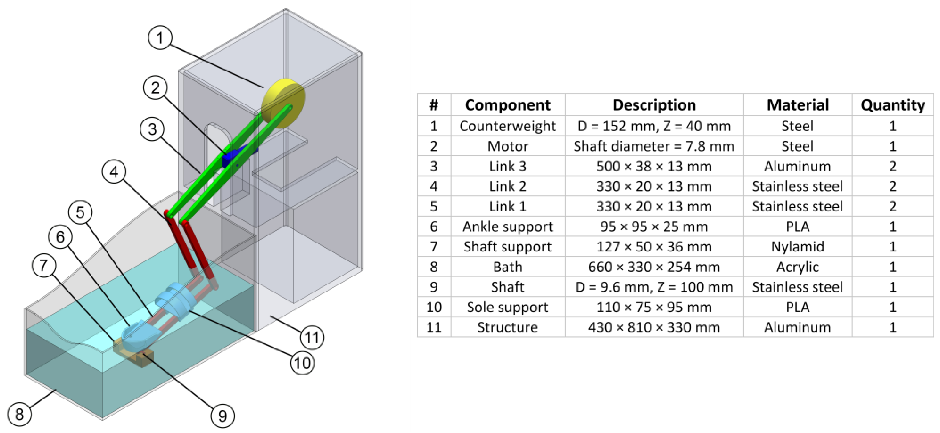
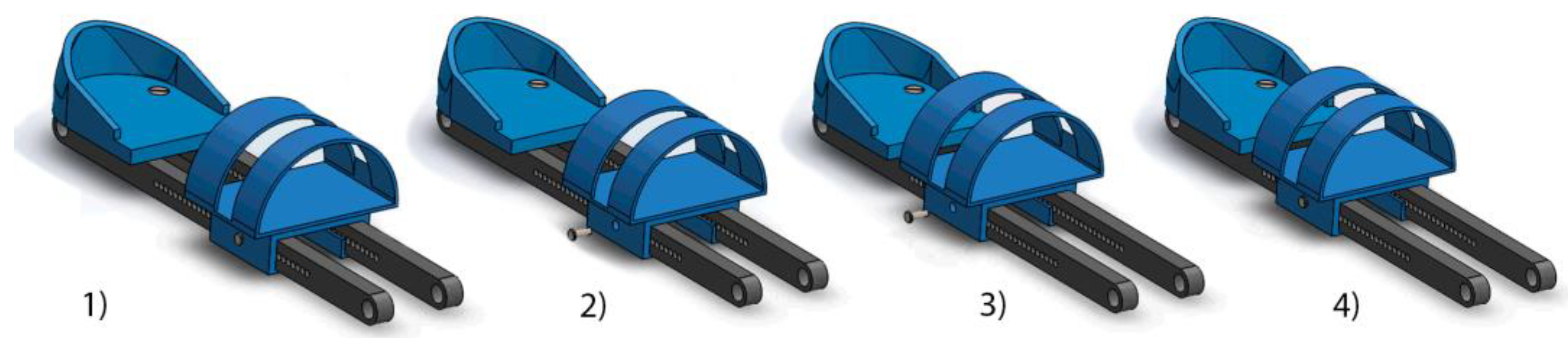
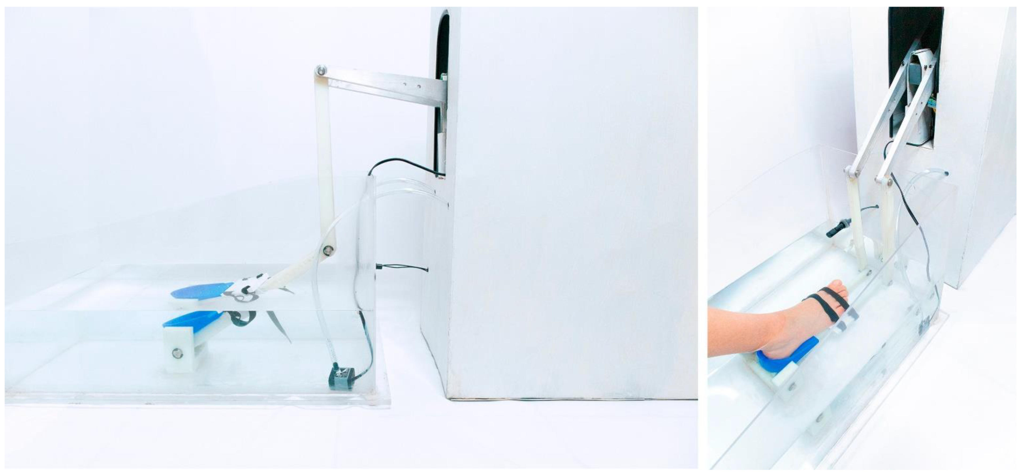
2.1. Robot Design

To obtain the technical specifications of the ankle rehabilitation robot—or the primary specifications of the design—anatomical data of the human ankle was considered [49]. The ankle joint can perform three different movements: (a) dorsiflexion/plantarflexion, (b) abduction/adduction, and (c) inversion/eversion. This study only addressed dorsiflexion/plantarflexion since these are the most important ankle rehabilitation movements practiced in therapy (see Figure 1). The design was based on the full range of movement (ROM) for ankle-joint rehabilitation—20° for dorsiflexion and 45° for plantarflexion. Thus, the target ROM for this study was set at 0° to 65°.
Computer-aided design (CAD) was used to model the three-dimensional (3D) ankle rehabilitation robot (see Figure 2). The ankle rehabilitation robot was designed to be used with a wide range of adult patients. It can perform rehabilitation on both feet (individually) since it is easy to fit and remove.
The sole support can easily and quickly be adjusted making it easy to satisfy a wide range of users when necessary (see Figure 3), which is an important aspect of the mechanical design. The mechanical design was based on one DOF to perform dorsiflexion-and-plantarflexion ankle rehabilitation movements (underwater). This simple mechanism covered the requirements of stability and robustness that are necessary to attain the full ROM for ankle-joint rehabilitation. The mechanical configuration contains some components and links working underwater; its purpose was to separate or isolate the electronic system from the water tank and to support the entire foot’s weight at the same time, thereby reducing the use of high-torque motors. The motor and counterweight are located inside the structure. The size of the structure was designed to match the anthropometric data of an average person and can be adjusted from the patient’s height of 1.5 m up to 1.8 m. The robot’s overall dimensions are selected as 1090 mm (length) × 330 mm (width) × 810 mm (height). The bath walls selected are 3 mm thick acrylic.

2.2. Modeling and Control of the Ankle Rehabilitation Robot

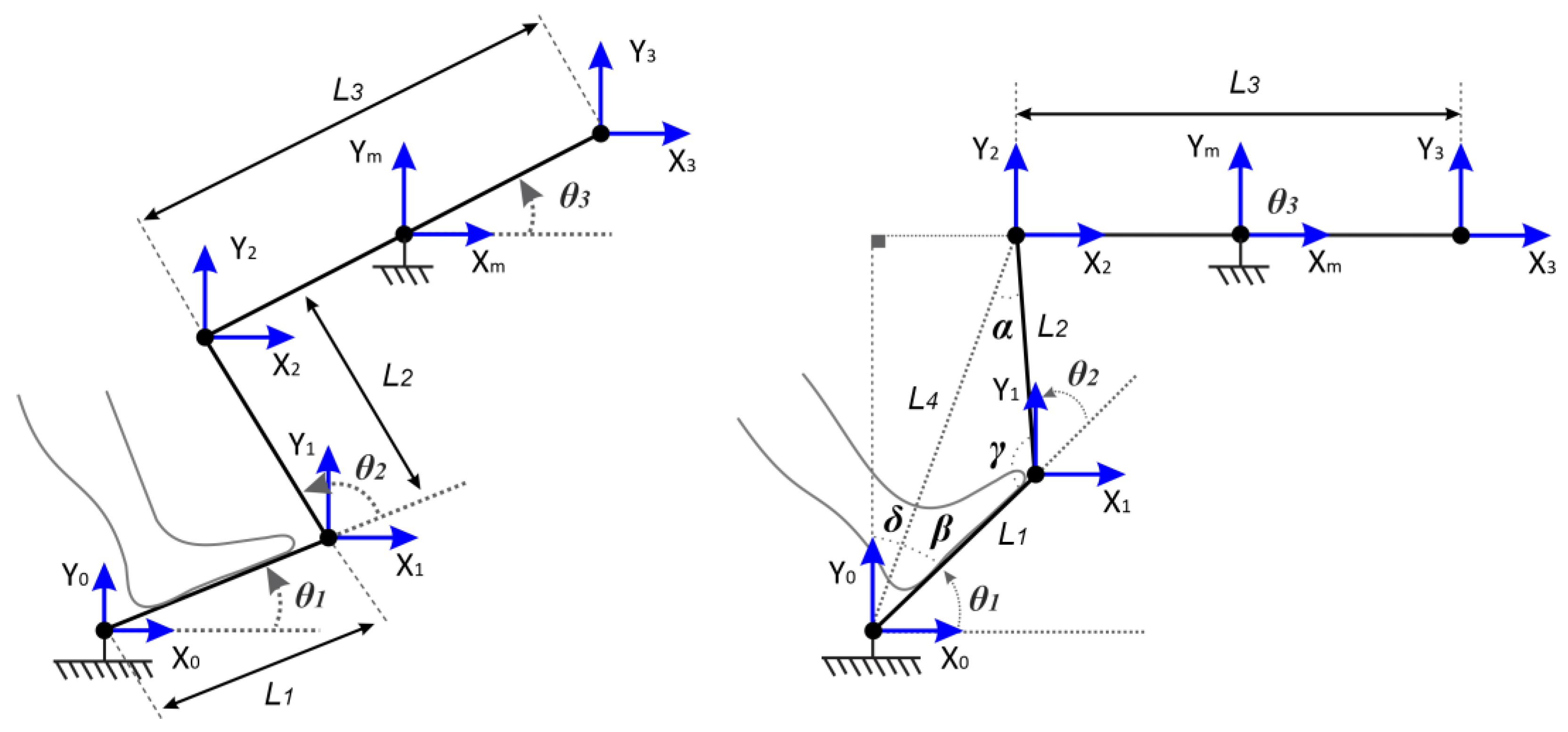
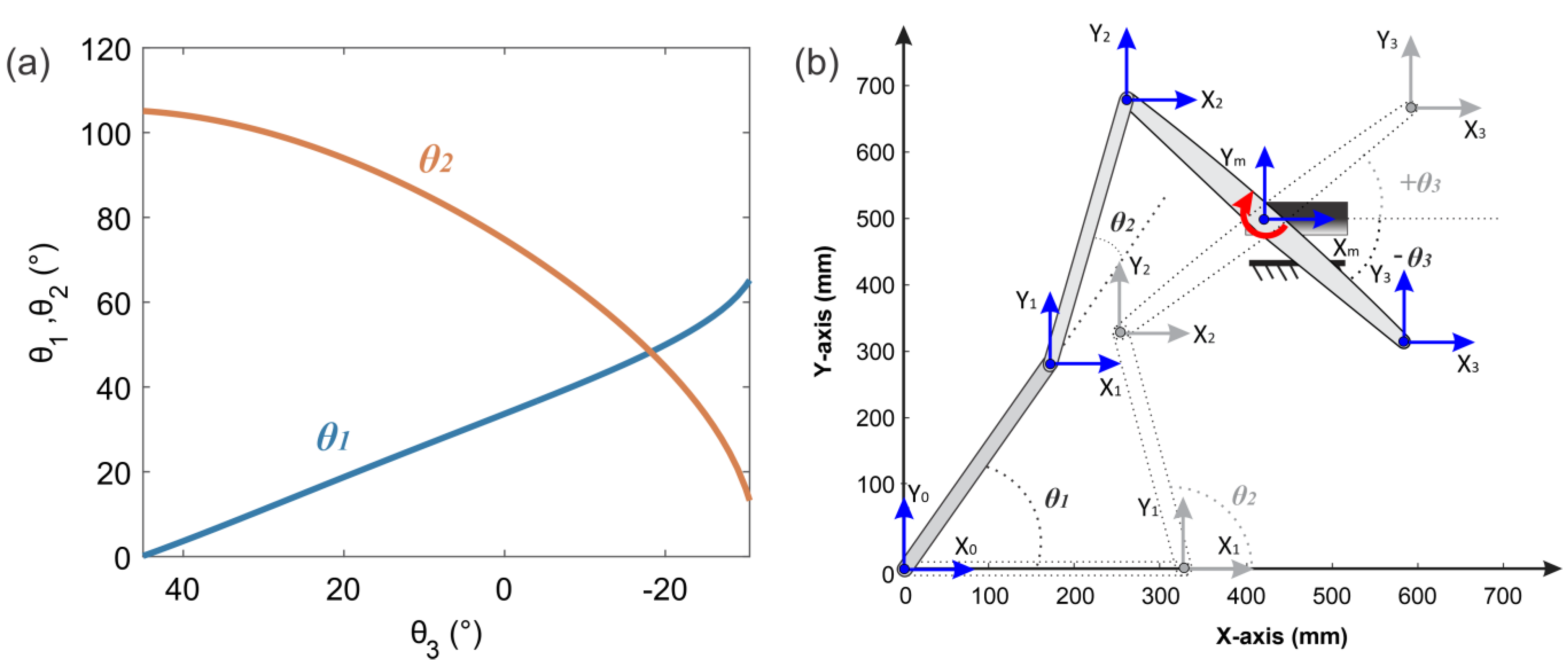
2.2.1. Kinematic Model

Consider the kinematic model shown in Figure 4. Here, X 0 , Y 0 , X 1 , Y 1 , X 2 ,   Y 2 ,   X 3 , Y 3 , X m and Y m are the Cartesian coordinates. L 1 , L 2 , and L 3 are the distances of Links 1, 2, and 3 respectively. L 4 is the reference distance. θ 1 , θ 2 , and θ 3 represent the angular positions of Links 1, 2, and 3 respectively. α , β , γ , and δ denote the complementary angles.
The equations describing the Cartesian coordinates of X 1 , Y 1 , X 2 , Y 2 , X 3 , and Y 3 are given by the following:
X 1 = L 1 c o s θ 1   ,   Y 1 = L 1 s i n θ 1
X 2 = X m 1 2 L 3 c o s θ 3   ,   Y 2 = Y m 1 2 L 3 s i n θ 3
X 3 = X m + 1 2 L 3 c o s θ 3   ,   Y 3 = Y m + 1 2 L 3 s i n θ 3
Right and up displacements were considered as positive movements with respect to the coordinates X 0 and Y 0 .
L 4 is obtained as follows:
L 4 = ( X 2 X 0 ) 2 + ( Y 2 Y 0 ) 2
By applying a procedure similar to the one previously shown, the remaining complementary angles are found to be as follows:
α = c o s 1 ( L 2 2 + L 4 2 L 1 2 2 L 2 L 4 ) ,   β = c o s 1 ( L 1 2 + L 4 2 L 2 2 2 L 1 L 4 ) ,   γ = c o s 1 ( L 1 2 + L 2 2 L 4 2 2 L 1 L 2 )
Finally, δ corresponds to:
δ = t g 1 ( X 2 Y 2 )
The kinematic model is expressed below:
θ 1 = π 2 β δ ,   θ 2 = π c o s 1 ( L 1 2 + L 2 2 L 4 2 2 L 1 L 2 )

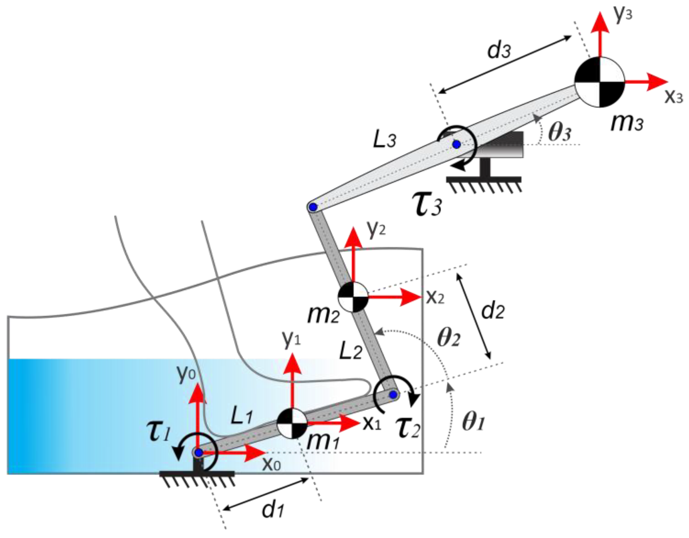
2.2.2. Dynamic Model

Consider the torque diagram that is shown in Figure 5, where θ 1 , θ 2 , and θ 3 are the generalized coordinates,   τ 1 and τ 2 are the generalized input torques, and τ 3 is the control input, m 1 , m 2 , and m 3 are the concentrated masses, d 1 is the distance from θ 1 to the center of L 1 , d 2 is the distance from θ 2 to the center of L 2 , and d 3 is the distance from θ 3 to the edge of L 3 .
The dynamic model of the ankle rehabilitation robot according to the Euler–Lagrange method can be expressed by
Q i = d d t ( L q ˙ i ) L q i + D q ˙ i
where L is the Lagrangian, K is the total kinetic energy, V is the total potential energy, D is the total damping of the robot, q i are the generalized coordinates, Q i are the external torques applied to the robot, and i = 1 ,   2 , and 3 .
The equation that describes the total kinetic energy of the robot is given by
K = 1 2 [ m 1 d 1 2 + m 2 ( L 1 2 + d 2 2 + 2 L 1 d 2 C 2 ) ] θ ˙ 1 2 + 1 2 ( m 2 d 2 2 ) θ ˙ 2 2 + 1 2 [ m 2 d 2 ( L 1 C 2 + d 2 ) ] θ ˙ 1 θ ˙ 2 + 1 2 m 3 d 3 2 θ ˙ 3 2
where C 2 = c o s θ 2 .
The equation that describes the total kinetic energy of the robot is given by
V = g ( m 1 d 1 S 1 + m 2 L 1 S 1 + m 2 d 2 S 12 + m 3 d 3 S 3 )
where S 1 = s i n θ 1 ,   S 3 = s i n θ 3 , S 12 = s i n ( θ 1 + θ 2 ) , and g is the gravitational acceleration.
The equation that describes the total damping of the robot is given by
D = 1 2 c 1 θ ˙ 1 2 + 1 2 c 2 θ ˙ 2 2 + 1 2 c 3 θ ˙ 3 2
where c 1 , c 2 , and c 3 represent the damping of Links 1, 2, and 3, respectively.
The Lagrangian is expressed below:
L = K V
L = 1 2 [ m 1 d 1 2 + m 2 ( L 1 2 + d 2 2 + 2 L 1 d 2 C 2 ) ] θ ˙ 1 2 + 1 2 ( m 2 d 2 2 ) θ ˙ 2 2 + 1 2 m 3 d 3 2 θ ˙ 3 2 + 1 2 [ m 2 d 2 ( L 1 C 2 + d 2 ) ] θ ˙ 1 θ ˙ 2 g ( m 1 d 1 S 1 + m 2 L 1 S 1 + m 2 d 2 S 12 + m 3 d 3 S 3 )
The equations that describe the dynamic behavior of the ankle rehabilitation robot are given below:
τ 1 = [ m 1 d 1 2 + m 2 ( L 1 2 + d 2 2 + 2 L 1 d 2 C 2 ) ] θ ¨ 1 + [ m 2 d 2 ( L 1 C 2 + d 2 ) ] θ ¨ 2 ( 2 m 2 L 1 d 2 S 2 ) θ ˙ 1 θ ˙ 2 ( m 2 d 2 L 1 S 2 ) θ ˙ 2 2 + c 1 θ ˙ 1 + g [ ( m 1 d 1 + m 2 L 1 ) C 1 + m 2 d 2 C 12 ]
τ 2 = [ m 2 d 2 ( L 1 C 2 + d 2 ) ] θ ¨ 1 + m 2 d 2 2 θ ¨ 2 + ( m 2 L 1 d 2 S 2 ) θ ˙ 1 2 + c 2 θ ˙ 2 + g m 2 d 2 C 12
τ 3 = m 3 d 3 2 θ ¨ 3 + c 3 θ ˙ 3 + g m 3 d 3 C 3
where S 2 = s i n θ 2 ,   C 3 = c o s θ 3 , C 12 = c o s ( θ 1 + θ 2 ) , τ 1 and τ 2 are completely passive, and τ 3 is active (control input).

2.2.3. Control Strategy of the Ankle Rehabilitation Robot

A standard proportional integral derivative (PID) controller with acceleration feed-forward compensation signals for robust tracking tasks of reference trajectories was proposed. The control strategy is given by
τ 3 = m 3 d 3 2 [ θ ¨ 3 * k d ( θ ˙ 3 θ ˙ 3 * ) k p ( θ 3 θ 3 * ) k i ( θ 3 θ 3 * ) d t ] + c 3 θ ˙ 3 + g m 3 d 3 C 3
where k d , k p , and k i are the derivative, proportional, and integral gains respectively and θ ¨ 3 * , θ ˙ 3 * , and θ 3 * correspond to the desired values. The definition of these values will be provided in the following lines.
The desired closed-loop dynamics where the error is e p = θ 3 θ 3 * is given by
θ ¨ 3 = θ ¨ 3 * k d ( θ ˙ 3 θ ˙ 3 * ) k p ( θ 3 θ 3 * ) k i ( θ 3 θ 3 * ) d t
e ¨ p + k d e ˙ p + k p e p + k i e p d t = 0
The parameters k d , k p , and k i were selected to ensure that the error dynamics was globally asymptotically stable. The characteristic polynomial (Hurwitz) is given by
H w ( s ) = ( s 2 + 2 ζ w n s + w n 2 ) ( s + p )
where k d = 2 ζ w n + p , k p = 2 p ζ w n + w n 2 , k i = p w n 2 ,     ζ > 0 , p > 0 , and   w n > 0 .
The desired reference trajectory is given by the following Bezier polynomial.
θ 3 * ( t ) = θ 3 * ( t s ) + ( θ 3 * ( t f ) θ 3 * ( t s )   ) σ ( t , t s , t f ) μ p 5 σ ( t , t s , t f ) = κ 1 κ 2 μ p + κ 3 μ p 2 + κ 6 μ p 5 μ p = t t s t f t s
where θ 3 * ( t s ) and θ 3 * ( t f ) are the initial and final desired positions, such that
θ 3 * ( t ) = { 0 0 t < t s σ ( t , t s , t f ) θ 3 * ( t f ) t s t < t f θ 3 * ( t f ) t > t f

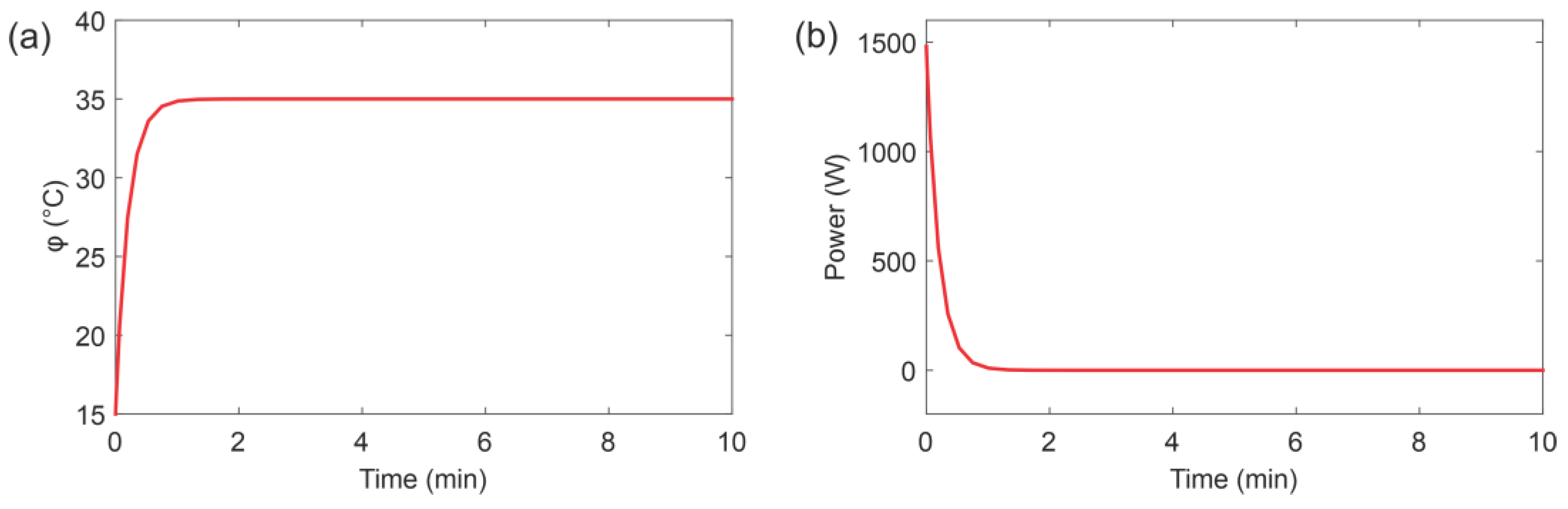
2.3. Modeling and Control of the Hot Water Recirculation System

Water provides thermal stability that permits the maintenance of constant temperature. For this study, a mathematical model was proposed based on the convection heat transfer equation [50]. The following assumptions and conditions were made: (a) heat loss was considered negligible, (b) there was no heat storage in the insulation, and (c) the water flow in the hot water recirculation system was evenly distributed. Figure 6 shows the schematic model, which is explained below.
The convection heat transfer equation is given by
q = H A Δ ϕ
where q is the heat flow rate, H is the convection coefficient, A is the normal area of the heat flow, and Δ ϕ is the temperature difference. For this equation, the water flow temperature in the recirculation system is kept constant. The heat input can suddenly change from H ^ to H ^ + h . The inlet and outlet water temperature, subsequently, changes from Φ i n to Φ i n + ϕ i n and from Φ o u t to Φ o u t + ϕ o u t respectively. For this case, h , C , and R are defined as follows:
h = G c ϕ o u t ,   C = M c ,   R = 1 G c
where c is the specific heat of water, R is the thermal resistance,   H ^ is the steady-state heat input, h is the heat input change, Φ i n is the steady-state inlet water temperature, ϕ i n is the inlet water temperature change, Φ o u t is the steady-state outlet water temperature, ϕ o u t is the outlet water temperature change, M is the mass of water, G is the mass flow rate of water, and C is the thermal capacitance of water.
The thermodynamic behavior of the hot water recirculation system is given by the following equation:
R C d ϕ o u t d t   +   ϕ o u t = ϕ i n   +   R h
The temperature controller design is explained below. The thermodynamic equation was rewritten as state variables to determine the hot water recirculation system behavior. This state-space description can be rewritten as follows:
x 1 = ϕ o u t ,     x 2 = ϕ ˙ o u t ,     x ˙ 1 = x 2
x 2 = h C + 1 R C ( ϕ i n x 1 )
For this hot water recirculation system, a temperature controller was proposed. The hot water recirculation system’s behavior is completely controllable, and it involves two control variables: h and ϕ i n . To control the temperature in the bath, a standard proportional (P) controller was proposed due to its simplicity. Introducing the temperature controller as a new control input, the thermodynamic equation can be rewritten as follows:
ϕ ˙ o = h C + 1 R C ( ϕ i n ϕ o u t ) = w
w = k p ( ϕ o u t ϕ o u t * )
ϕ ˙ o + k p ( ϕ o u t ϕ o u t * ) = 0
where w is the new control input, ϕ o u t * is the desired temperature, and k p is the temperature controller gain.
Defining the output temperature tracking error as e t , the temperature controller gain can be obtained using the Laplace transformation as follows:
e t = ϕ o u t ϕ o u t *
e ˙ t + k p e t = 0
s + k p = 0 ,     k p > 0

3. Results

3.1. Kinematic Simulation

A kinematic analysis was conducted to verify the ROM that is suitable for ankle-joint rehabilitation movements. Table 1 shows the input parameters for kinematic simulation.
Figure 7 shows the kinematic ankle dorsiflexion rehabilitation movement simulation. θ 1 started at 0° and ended at 65°. θ 2 started at 105° and ended at 13°. θ 3 started at 45° and ended at −30.5° (clockwise rotation). Figure 8 shows the kinematic ankle plantarflexion rehabilitation movement simulation. θ 1 started at 65° and ended at 0°. θ 2 started at 13° and ended at 105°. θ 3 started at −30.5° and ended at 45° (counterclockwise rotation). The kinematic analysis indicated that the ankle rehabilitation movements dorsiflexion ( θ 1 = 20 ° ) and plantarflexion ( θ 1 = 45 ° ) were correctly reached using the proposed input simulation parameters.

3.2. Hot Water Recirculation System Simulation

Table 2 shows the input parameters for hot water recirculation system simulation. These temperatures permit lengthy rehabilitation durations that are sufficient to ensure therapeutic effects without chilling or overheating. Typical therapy temperature operates in the range between 33 °C and 35 °C.
To assess the performance of the temperature controller in the hot water recirculation system, the setpoint was established at 35 °C and the simulation time was set as 10 min. The temperature was registered with a sampling time of one second. Figure 9 shows the hot water recirculation system response. The hot water recirculation system attained the desired temperature in less than 90 s, and the temperature controller used 1486 W during the transient state and 20 W to maintain a steady state. The hot water recirculation system simulation indicated that the P controller is suitable to maintain the desired temperature in the bath during ankle-joint rehabilitation movements.

3.3. Dynamic Simulation

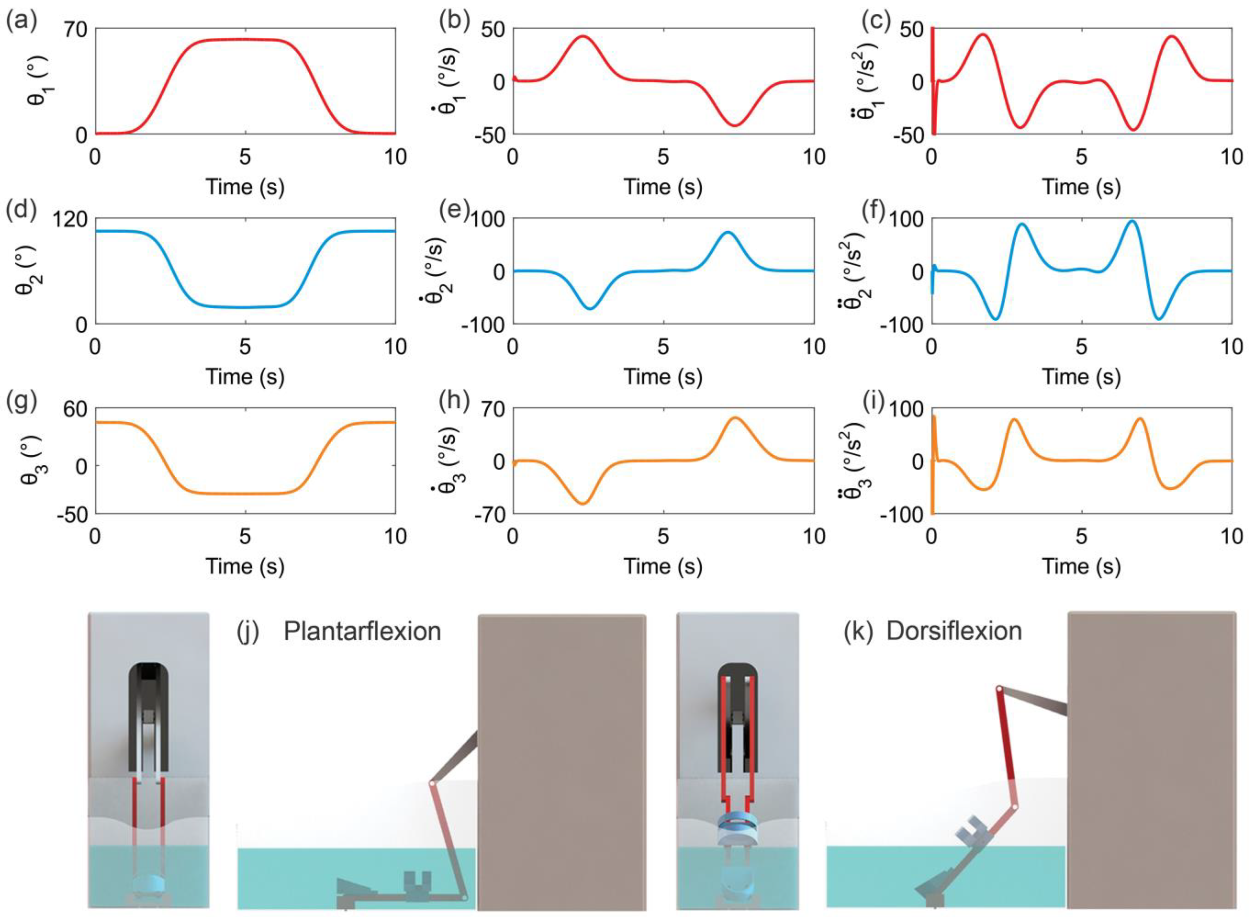
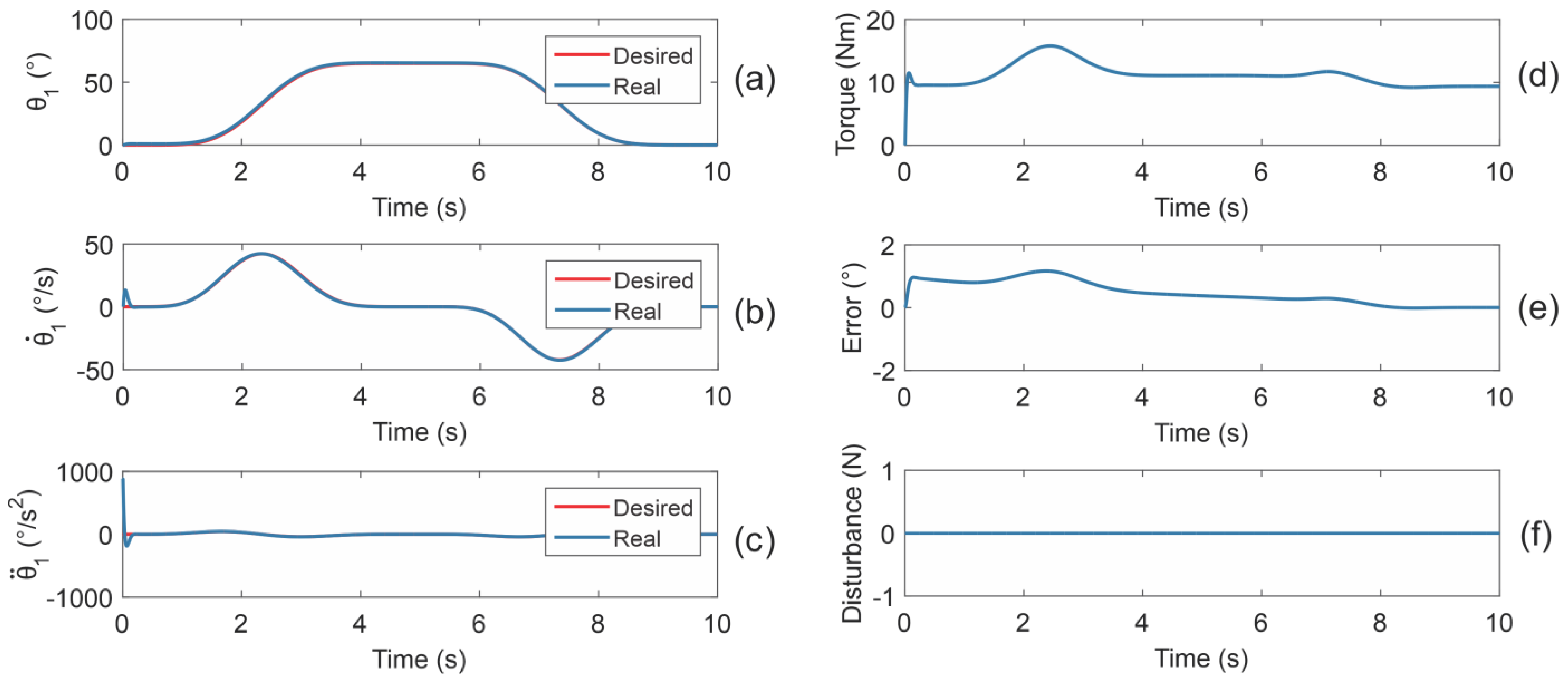
3.3.1. Reference Trajectory Tracking Simulations Using the Dynamic Model

To predict the dynamic behavior of the ankle rehabilitation robot, the dynamic model—based on Equations (14)–(16)—and the angular position controller—based on Equation (17)—were simulated using MATLAB®. Table 3 shows the input parameters for dynamic model simulation.
The following angular position controller’s gains—selected by trial-and-error method—were used: ζ = 0.07 ,   p = 0.1 , and w n = 5 . The Bezier polynomial coefficients were selected as κ 1 = 252, κ 2 = 1050, κ 3 = 1800, κ 4 = 1575, κ 5 = 700, and κ 6 = 126. To assess the performance of the angular position controller, the desired trajectory was established from 0° to 65°, and the simulation time was set at 5 s (from plantarflexion to dorsiflexion); following this, the desired trajectory was established from 65° to 0° and the simulation time was set at 5 s (from dorsiflexion to plantarflexion). Figure 10 shows the ankle rehabilitation robot response. The trajectories or rehabilitation movements— θ 1 started at 0° (plantarflexion), reached 65° (dorsiflexion), and ended at 0° (plantarflexion)—were smooth and precise enough to keep the ankle comfortable and safe. As demonstrated, only one standard PID controller with acceleration feed-forward compensation signals was sufficient for the reference trajectory tracking simulations using the dynamic model.

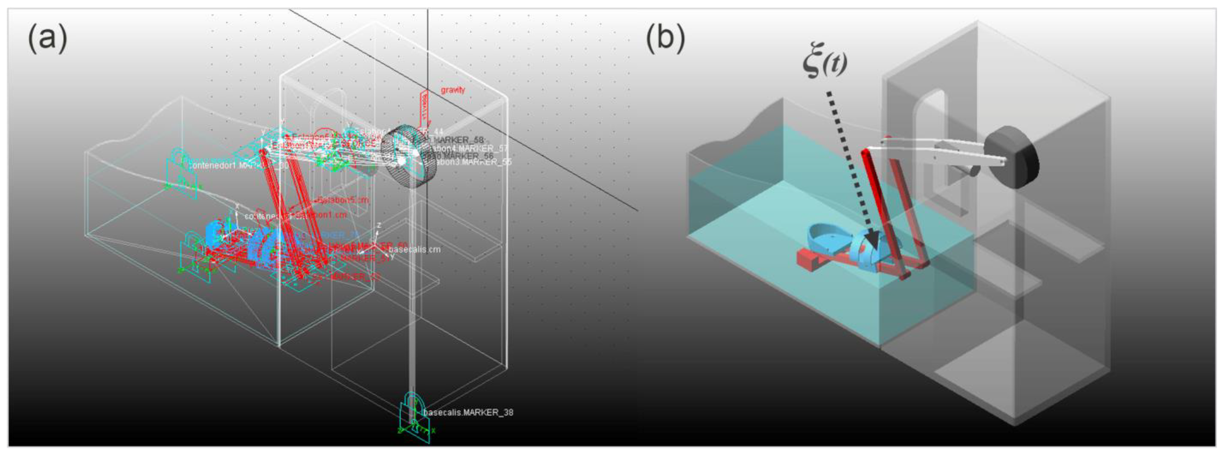
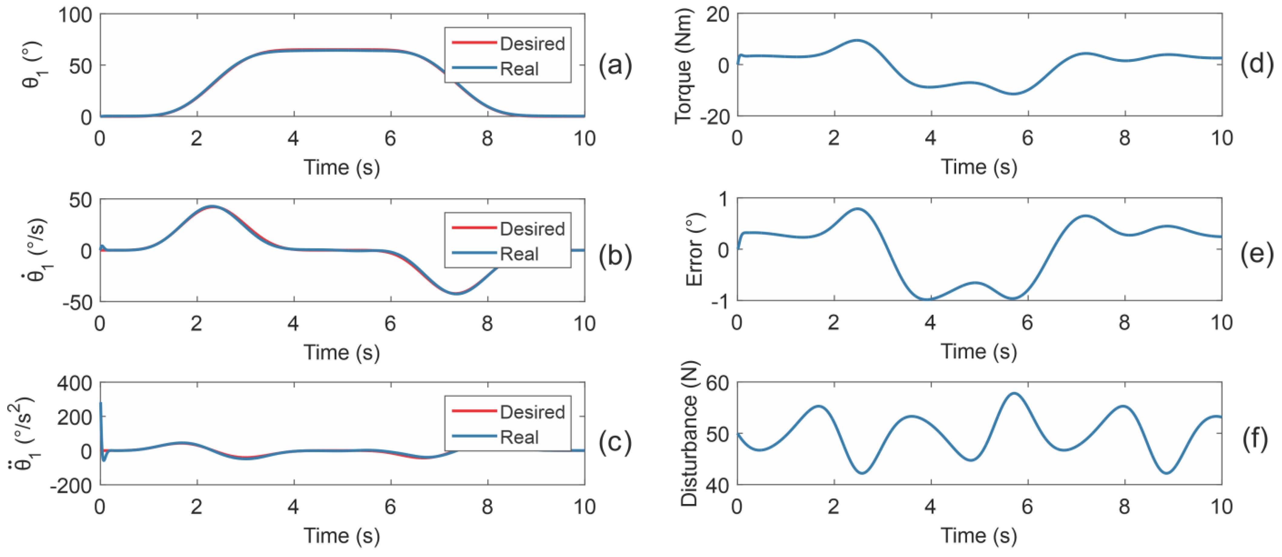
3.3.2. Reference Trajectory Tracking Simulations Using a Virtual Prototype

The reference trajectory tracking simulations using the dynamic model indicated that the angular position controller is adequate to control the ankle rehabilitation robot; however, disturbances are necessary to corroborate these simulation results. To evaluate the control strategy under different operation conditions, a virtual prototype is proposed (see Figure 11). Three different possible scenarios were contemplated: (a) without a disturbance input, (b) with a constant disturbance input, and (c) with an unknown disturbance input. The input disturbances were applied at the sole support to simulate either unknown external forces generated by structural nonlinearities, nonlinear frictions, parametric uncertainty, undesired vibrations, unknown forces generated by the patient’s leg weight, or unknown disturbances caused by the movement and pressure of water.
The angular position controller’s gains, Bezier polynomial coefficients, parameters, and trajectories were the same as those presented in the previous simulations. Figure 12 shows the reference trajectory tracking simulation without a disturbance input, ξ ( t ) = 0 N. The angular position error varied from −0.09 to 1.15°. The torque varied from 0 to 16 Nm. Figure 13 shows the reference trajectory tracking simulation with a constant disturbance input, ξ ( t ) = 50 N—this input signal pretends to simulate forces generated by the patient’s leg weight (5 kg). The angular position error varied from −0.95 to 0.79°. The torque varied from −9.51 to 8.52 Nm. Figure 14 shows the reference trajectory tracking simulation with an unknown disturbance input, ξ ( t ) = 50 + 5 s i n ( 3 t ) exp ( s i n t c o s t ) N. The angular position error varied from −1 to 0.8°. The torque varied from −11 to 10 Nm.
These simulation results indicated that unknown disturbances applied in the ankle rehabilitation robot vary the intensity of the angular position controller action; even so, the angular position controller could accurately follow the desired position trajectories. The reference trajectory tracking simulations using a virtual prototype demonstrated the robustness of the proposed output feedback control strategy. In both simulations with unknown disturbances, the ankle rehabilitation robot remained stable at different disturbance input signals. This implies that the angular position controller’s gains were adequately selected. As demonstrated, the control strategy could reproduce ankle-joint rehabilitation movements despite unknown disturbances.

3.4. Experimental Results

Simulation results indicated that standard P and PID controllers are adequate to control the ankle rehabilitation robot; however, experimental tests are necessary to corroborate them. Figure 15 shows the ankle rehabilitation robot incorporating aquatic therapy.
Due to safety issues, it is currently not possible to perform experiments on patients with ankle disabilities. Nevertheless, the results underline the benefits of the system. Figure 16 shows the experimental results of the robot performing ankle rehabilitation exercises (dorsiflexion/plantarflexion) underwater. The movement position of the ankle is continuously tracked by the robot. The position values and time history were recorded in real time on the database.
The robot was able to guide the platform (sole support) to follow the desired position trajectory accurately. This test showed that the robotic system can perfectly repeat the desired trajectories. The experimental data show that the friction of the mechanism and the weight of the patient’s leg cause a minimal disturbance on the desired trajectory tracking. The use of these controllers is satisfying in terms of rehabilitation specifications. The results obtained demonstrate the stability and robustness of the device. The prototype was fully functional and robust using simple controllers to track flowing planned trajectories.
The experimental results demonstrated the excellent performance of the ankle-joint rehabilitation system. The prototype can reproduce the ankle rehabilitation movements of dorsiflexion/plantarflexion underwater. Such rehabilitation device can have a great impact in improving physiotherapeutic outcomes in ankle-joint rehabilitation. One key feature over previous approaches [34,35,36,37,38,39,40,41,42,43,44,45,46,47] is that they only try to perform physical exercises, i.e., only ankle rehabilitation movements, while our approach combines land-based therapy and aquatic therapy into one device, that implies, the design of a new generation of robots not only for ankle rehabilitation but also for upper and lower limbs.

4. Conclusions

This paper presented the design, development, and control of a therapeutic robot incorporating aquatic therapy for ankle rehabilitation. To conduct this study, an ankle rehabilitation robot was designed, modeled, developed, and controlled. The control strategy was proposed to follow the desired trajectories, and a hot water recirculation system was modeled and controlled. The control strategy was proposed to maintain a stable temperature. Simulation and experimental results were presented to understand the kinematic, thermodynamic, and dynamic behaviors of the ankle rehabilitation robot. A standard P controller was used to keep the temperature inside the hot water recirculation system stable. A standard PID controller with acceleration feed-forward compensation was applied to follow the desired trajectories despite the different unknown input disturbances. The design and control presented here indicate that this study is adequate for undertaking the next step—validation with patients.
The present study was developed to improve the field of physical rehabilitation. A synergistic combination of mechanical engineering, modeling, control theory, thermal science, and mechatronics was ensured to provide a new generation of ankle rehabilitation robots that can perform underwater ankle rehabilitation movements. These findings suggest that this ankle rehabilitation robot can be adopted in large rehabilitation applications for reducing pain; possible applications in ankle rehabilitation will be noticed in muscle spasticity and joint stiffness. This new technology has extensive rehabilitative potential for many patients who require effective and efficient land-based therapy incorporating aquatic therapy to their daily rehabilitation program, extending from the treatment of acute injuries through chronic illnesses and diseases.
This study observed that the development of this ankle rehabilitation robot is complex in terms of synergistic combination. Innovation in the design and control of rehabilitation devices requires reaching a balance between the basic mechanical structures and their overall control. This study seeks to provide a point of departure featuring practical developments in rehabilitation robotics. Importance will be given to aspects of patient safety—this is a crucial issue for future research. Further studies should increase the number of DOF and the complexity of the control strategies. We believe that reducing pain by using aquatic therapy during therapies is the next step in the field of rehabilitation and that it can be applied to treat not only the lower limbs but also the upper limbs.

Author Contributions

Conceptualization, C.H.G.-V. and O.M.-L.; methodology, A.B.-O.; software, J.A.B.-M.; validation, O.C.-D. and J.A.B.-T.; formal analysis, O.M.-L.; investigation, O.D.-O.; resources, J.T.-O.; data curation, J.A.B.-M.; writing—original draft preparation, C.A.C.-O.; writing—review and editing, O.C.-D.; visualization, J.A.B.-T.; supervision, A.B.-O.; project administration, F.A.G.-B.; funding acquisition, C.H.G.-V. All authors have read and agreed to the published version of the manuscript.

Funding

This research was funded by PRODEP and UAA, Grant Numbers: PII21-8N and PII21-3.

Institutional Review Board Statement

Not applicable.

Informed Consent Statement

Not applicable.

Data Availability Statement

Not applicable.

Acknowledgments

The authors thank the Autonomous University of Aguascalientes for the support received to carry out this work.

Conflicts of Interest

The authors declare no conflict of interest.

References

  1. Delahunt, E.; Remus, A. Risk factors for lateral ankle sprains and chronic ankle instability. J. Athl. Train. 2019, 54, 611–616. [Google Scholar] [CrossRef] [Green Version]
  2. Kisner, C.; Colby, L.A. Therapeutic Exercise: Foundations and Techniques, 6th ed.; F.A. Davis Company: Philadelphia, PA, USA, 2012; pp. 849–894. [Google Scholar]
  3. Guzmán Valdivia, C.H.; Carrera Escobedo, J.L.; Blanco Ortega, A.; Oliver Salazar, M.A.; Gómez Becerra, F.A. Diseño y control de un sistema interactivo para la rehabilitación de tobillo: TobiBot. Ing. Mecánica Tecnol. Desarro. 2014, 5, 255–264. [Google Scholar]
  4. Becker, B.E. Aquatic therapy: Scientific foundations and clinical rehabilitation applications. PM&R 2009, 1, 859–872. [Google Scholar] [CrossRef]
  5. Baena-Beato, P.Á.; Artero, E.G.; Arroyo-Morales, M.; Robles-Fuentes, A.; Gatto-Cardia, M.C.; Delgado-Fernández, M. Aquatic therapy improves pain, disability, quality of life, body composition and fitness in sedentary adults with chronic low back pain. A controlled clinical trial. Clin. Rehabil. 2014, 28, 350–360. [Google Scholar] [CrossRef] [PubMed]
  6. Bender, T.; Karagülle, Z.; Bálint, G.P.; Gutenbrunner, C.; Bálint, P.V.; Sukenik, S. Hydrotherapy, balneotherapy, and spa treatment in pain management. Rheumatol. Int. 2005, 25, 220–224. [Google Scholar] [CrossRef] [PubMed]
  7. Prins, J.; Cutner, D. Aquatic therapy in the rehabilitation of athletic injuries. Clin. Sports Med. 1999, 18, 447–461. [Google Scholar] [CrossRef]
  8. Levin, S. Aquatic Therapy: A splashing success for arthritis and injury rehabilitation. Physician Sportsmed. 1991, 19, 119–126. [Google Scholar] [CrossRef]
  9. Broach, E.; Dattilo, J. Aquatic therapy: A viable therapeutic recreation intervention. Ther. Recreat. J. 1996, 30, 213–229. [Google Scholar]
  10. Konlian, C. Aquatic therapy: Making a wave in the treatment of low back injuries. Orthop. Nurs. 1999, 18, 11–20. [Google Scholar] [CrossRef] [PubMed]
  11. Wolfe, M.W.; UHL, T.L.; Mattacola, C.G.; Mccluskey, L.C. Management of Ankle Sprains. Am. Fam. Physician 2001, 63, 93–105. [Google Scholar]
  12. Pournot, H.; Bieuzen, F.; Duffield, R.; Lepretre, P.M.; Cozzolino, C.; Hausswirth, C. Short term effects of various water immersions on recovery from exhaustive intermittent exercise. Eur. J. Appl. Physiol. 2011, 111, 1287–1295. [Google Scholar] [CrossRef]
  13. McNeal, R.L. Aquatic therapy for patients with rheumatic disease. Rheum. Dis. Clin. N. Am. 1990, 16, 915–929. [Google Scholar] [CrossRef]
  14. Thompson, C.; Kelsberg, G.; St Anna, L.; Poddar, S. Clinical inquiries. Heat or ice for acute ankle sprain? J. Fam. Pract. 2003, 52, 642–643. [Google Scholar] [PubMed]
  15. Nordin, M.; Frankel, V.H. Basic Biomechanics of the Musculoskeletal System, 4th ed.; Lippincott Williams & Wilkins: Philadelphia, PA, USA, 2012; pp. 803–835. [Google Scholar]
  16. Hinman, R.S.; Heywood, S.E.; Day, A.R. Aquatic physical therapy for hip and knee osteoarthritis: Results of a single-blind randomized controlled trial. Phys. Ther. 2007, 87, 32–43. [Google Scholar] [CrossRef]
  17. Krebs, H.I.; Dipietro, L.; Levy-Tzedek, S.; Fasoli, S.E.; Rykman-Berland, A.; Zipse, J.; Fawcett, J.A.; Stein, J.; Poizner, H.; Lo, A.C.; et al. A paradigm shift for rehabilitation robotics. IEEE Eng. Med. Biol. Mag. 2008, 27, 61–70. [Google Scholar] [CrossRef]
  18. Tejima, N. Rehabilitation robotics: A review. Adv. Robot. 2001, 14, 551–564. [Google Scholar] [CrossRef]
  19. Rodríguez-León, J.F.; Chaparro-Rico, B.D.M.; Russo, M.; Cafolla, D. An Autotuning Cable-Driven Device for Home Rehabilitation. J. Healthc. Eng. 2021, 2021, 6680762. [Google Scholar] [CrossRef]
  20. Hussain, S.; Jamwal, P.K.; Vliet, P.V.; Brown, N.A.T. Robot Assisted Ankle Neuro-Rehabilitation: State of the art and Future Challenges. Expert Rev. Neurother. 2021, 21, 111–121. [Google Scholar] [CrossRef] [PubMed]
  21. Guzmán-Valdivia, C.H.; Blanco-Ortega, A.; Oliver-Salazar, M.A.; Gómez-Becerra, F.A.; Carrera-Escobedo, J.L. HipBot–The design, development and control of a therapeutic robot for hip rehabilitation. Mechatronics 2015, 30, 55–64. [Google Scholar] [CrossRef]
  22. Becerra, F.A.G.; Ortega, A.B.; Beltrán, C.D.G.; Valdivia, C.H.G.; Arcega, R.O.D. Design and control of a new parallel robot for the rehabilitation of the hip-knee. IEEE Lat. Am. Trans. 2018, 16, 1314–1319. [Google Scholar] [CrossRef]
  23. Azcaray, H.; Blanco, A.; García, C.; Adam, M.; Reyes, J.; Guerrero, G.; Guzmán, C. Robust GPI Control of a New Parallel Rehabilitation Robot of Lower Extremities. Int. J. Control Autom. Syst. 2018, 16, 2384–2392. [Google Scholar] [CrossRef]
  24. Guzmán, C.H.; Blanco, A.; Brizuela, J.A.; Gómez, F.A. Robust control of a hip–joint rehabilitation robot. Biomed. Signal Process. Control 2017, 35, 100–109. [Google Scholar] [CrossRef]
  25. Khalid, Y.M.; Gouwanda, D.; Parasuraman, S. A review on the mechanical design elements of ankle rehabilitation robot. Proc. Inst. Mech. Eng. Part H 2015, 229, 452–463. [Google Scholar] [CrossRef]
  26. Wang, X.; Wang, H.; Hu, X.; Tian, Y.; Lin, M.; Yan, H.; Niu, J.; Sun, L. Adaptive Direct Teaching Control with Variable Load of the Lower Limb Rehabilitation Robot (LLR-II). Machines 2021, 9, 142. [Google Scholar] [CrossRef]
  27. Díaz, I.; Gil, J.J.; Sánchez, E. Lower-limb robotic rehabilitation: Literature review and challenges. J. Robot. 2011, 2011, 759764. [Google Scholar] [CrossRef]
  28. Li, J.; Fan, W.; Dong, M.; Rong, X. Research on control strategies for ankle rehabilitation using parallel mechanism. Cogn. Comput. Syst. 2020, 2, 105–111. [Google Scholar] [CrossRef]
  29. Alcocer, W.; Vela, L.; Blanco, A.; González, J.; Oliver, M. Major trends in the development of ankle rehabilitation devices. Dyna 2012, 176, 45–55. [Google Scholar]
  30. Blaya, J.A.; Herr, H. Adaptive control of a variable-impedance ankle-foot orthosis to assist drop-foot gait. IEEE Trans. Neural Syst. Rehabil. Eng. 2004, 12, 24–31. [Google Scholar] [CrossRef] [PubMed]
  31. Ferris, D.P.; Czerniecki, J.M.; Hannaford, B. An ankle-foot orthosis powered by artificial pneumatic muscles. J. Appl. Biomech. 2005, 21, 189–197. [Google Scholar] [CrossRef] [Green Version]
  32. Hussain, S.; Xie, S.Q.; Jamwal, P.K. Effect of cadence regulation on muscle activation patterns during robot assisted gait: A dynamic simulation study. IEEE J. Biomed. Health Inform. 2013, 17, 442–451. [Google Scholar] [CrossRef]
  33. Saglia, J.A.; Tsagarakis, N.G.; Dai, J.S.; Caldwell, D.G. A high-performance redundantly actuated parallel mechanism for ankle rehabilitation. Int. J. Robot. Res. 2009, 28, 1216–1227. [Google Scholar] [CrossRef]
  34. Yoon, J.; Ryu, J.; Lim, K.B. Reconfigurable ankle rehabilitation robot for various exercises. J. Robot. Syst. 2006, 22, 15–33. [Google Scholar] [CrossRef]
  35. Jamwal, P.K.; Hussain, S.; Mir-Nasiri, N.; Ghayesh, M.H.; Xie, S.Q. Tele-rehabilitation using in-house wearable ankle rehabilitation robot. Assist. Technol. 2018, 30, 24–33. [Google Scholar] [CrossRef] [PubMed] [Green Version]
  36. Zhang, M.; McDaid, A.; Veale, A.J.; Peng, Y.; Xie, S.Q. Adaptive Trajectory tracking control of a parallel ankle rehabilitation robot with joint-space force distribution. IEEE Access 2019, 7, 85812–85820. [Google Scholar] [CrossRef]
  37. Chang, T.C.; Zhang, X.D. Kinematics and reliable analysis of decoupled parallel mechanism for ankle rehabilitation. Microelectron. Reliab. 2019, 99, 203–212. [Google Scholar] [CrossRef]
  38. Liu, Q.; Wang, C.; Long, J.J.; Sun, T.; Duan, L.; Zhang, X.; Zhang, B.; Shen, Y.; Shang, W.; Lin, Z.; et al. Development of a New Robotic Ankle Rehabilitation Platform for Hemiplegic Patients after Stroke. J. Healthc. Eng. 2018, 2018, 3867243. [Google Scholar] [CrossRef] [Green Version]
  39. Ai, Q.; Zhu, C.; Zuo, J.; Meng, W.; Liu, Q.; Xie, S.Q.; Yang, M. Disturbance-Estimated Adaptive Backstepping Sliding Mode Control of a Pneumatic Muscles-Driven Ankle Rehabilitation Robot. Sensors 2018, 18, 66. [Google Scholar] [CrossRef] [Green Version]
  40. Jamwal, P.K.; Hussain, S.; Ghayesh, M.H.; Rogozina, S.V. Impedance control of an intrinsically compliant parallel ankle rehabilitation robot. IEEE Trans. Ind. Electron. 2016, 63, 3638–3647. [Google Scholar] [CrossRef]
  41. Ayas, M.S.; Altas, I.H. Fuzzy logic based adaptive admittance control of a redundantly actuated ankle rehabilitation robot. Control Eng. Pract. 2017, 59, 44–54. [Google Scholar] [CrossRef]
  42. Covaciu, F.; Pisla, A.; Iordan, A.-E. Development of a Virtual Reality Simulator for an Intelligent Robotic System Used in Ankle Rehabilitation. Sensors 2021, 21, 1537. [Google Scholar] [CrossRef]
  43. Abu-Dakka, F.J.; Valera, A.; Escalera, J.A.; Abderrahim, M.; Page, A.; Mata, V. Passive Exercise Adaptation for Ankle Rehabilitation Based on Learning Control Framework. Sensors 2020, 20, 6215. [Google Scholar] [CrossRef]
  44. Zuo, S.; Li, J.; Dong, M.; Zhou, X.; Fan, W.; Kong, Y. Design and Performance Evaluation of a Novel Wearable Parallel Mechanism for Ankle Rehabilitation. Front. Neurorobot. 2020, 14, 9. [Google Scholar] [CrossRef] [PubMed] [Green Version]
  45. Zhang, J.; Liu, C.; Liu, T.; Qi, K.; Niu, J.; Guo, S. Module combination based configuration synthesis and kinematic analysis of generalized spherical parallel mechanism for ankle rehabilitation. Mech. Mach. Theory 2021, 166, 104436. [Google Scholar] [CrossRef]
  46. Russo, M.; Ceccarelli, M. Analysis of a Wearable Robotic System for Ankle Rehabilitation. Machines 2020, 8, 48. [Google Scholar] [CrossRef]
  47. Hau, C.T.; Gouwanda, D.; Gopalai, A.A.; Low, C.Y.; Hanapiah, F.A. Gamification and Control of Nitinol Based Ankle Rehabilitation Robot. Biomimetics 2021, 6, 53. [Google Scholar] [CrossRef]
  48. Alvarez-Perez, M.G.; Garcia-Murillo, M.A.; Cervantes-Sánchez, J.J. Robot-assisted ankle rehabilitation: A review. Disabil. Rehabil. Assist. Technol. 2020, 15, 394–408. [Google Scholar] [CrossRef]
  49. Blanco, A.; Gómez, F.A.; Olivares, V.H.; Abundez, A.; Colín, J. Design and development of a parallel robot based on an XY table for ankle rehabilitation. Int. J. Autom. Control 2015, 9, 89–106. [Google Scholar] [CrossRef]
  50. Hollands, K.G.T.; Raithby, G.D.; Konicek, L. Correlation equations for free convection heat transfer in horizontal layers of air and water. Int. J. Heat Mass Transf. 1974, 18, 879–884. [Google Scholar] [CrossRef]
Figure 1. Ankle rehabilitation movements.
Machines 09 00254 g001
Figure 2. Robot design.
Machines 09 00254 g002
Figure 3. The mechanism that makes the robot easy to fit and remove.
Machines 09 00254 g003
Figure 4. Kinematic model.
Machines 09 00254 g004
Figure 5. Torque diagram.
Machines 09 00254 g005
Figure 6. Schematic model.
Machines 09 00254 g006
Figure 7. Kinematic ankle dorsiflexion rehabilitation movement simulation. (a) angular positions θ 1 and θ 2 with respect to θ 3 , (b) two–dimensional graphical representation.
Machines 09 00254 g007
Figure 8. Kinematic ankle plantarflexion rehabilitation movement simulation. (a) angular positions θ 1 and θ 2 with respect to θ 3 , (b) two–dimensional graphical representation.
Machines 09 00254 g008
Figure 9. Hot water recirculation system response. (a) temperature sensor output, (b) temperature controller action.
Machines 09 00254 g009
Figure 10. Ankle rehabilitation robot response. (ac) are respectively the angular position, velocity, and acceleration of θ 1 , (df) are respectively the angular position, velocity, and acceleration of θ 2 , (gi) are respectively the angular position, velocity, and acceleration of θ 3 , (j) is the plantarflexion position, and (k) is the dorsiflexion position.
Machines 09 00254 g010
Figure 11. Virtual prototype. (a) Parts, workspace, and Cartesian coordinate system, and (b) robot simulation using MSC ADAMS/View®.
Machines 09 00254 g011
Figure 12. Reference trajectory tracking simulation without a disturbance input. (a), (b), and (c) are respectively the angular position, velocity, and acceleration of θ 1 , (d) is the torque, (e) is the error, and (f) is the disturbance.
Machines 09 00254 g012
Figure 13. Reference trajectory tracking simulation with a constant disturbance input. (a), (b), and (c) are respectively the angular position, velocity, and acceleration of θ 1 , (d) is the torque, (e) is the error, and (f) is the disturbance.
Machines 09 00254 g013
Figure 14. Reference trajectory tracking simulation with an unknown disturbance input. (a), (b), and (c) are respectively the angular position, velocity, and acceleration of θ 1 , (d) is the torque, (e) is the error, and (f) is the disturbance.
Machines 09 00254 g014
Figure 15. Ankle rehabilitation robot incorporating aquatic therapy.
Machines 09 00254 g015
Figure 16. Experimental results of the robot performing dorsiflexion and plantarflexion. (a) temperature sensor output, (b) PID controller tracking performance.
Machines 09 00254 g016
Table 1. Input parameters for kinematic simulation.
ParameterValue (mm)
X 0 ,   Y 0 0
X m 420
Y m 496
L 1 330
L 2 330
L 3 500
Table 2. Input parameters for hot water recirculation system simulation.
ParameterValue
R 16.97 °C s/kcal
C 37 kcal/°C
G 0.05890 kg/s
M 37 kg
Φ i 15 °C
ϕ o * 35 °C
k p 100
Table 3. Input parameters for dynamic model simulation.
ParameterValue
L 1 ,   L 2 330 mm
L 3 500 mm
d 1 ,   d 2 165 mm
d 3 250 mm
m 1 0.437 kg
m 2 0.244 kg
m 3 5.783 kg
c 1 ,   c 2 ,   c 3 0.1 Ns/m
Publisher’s Note: MDPI stays neutral with regard to jurisdictional claims in published maps and institutional affiliations.

