1. Introduction
The aviation hydraulic pump is the core component of an aircraft hydraulic system. It converts mechanical energy into hydraulic energy and controls the action of the actuators to realize the adjustment of the aircraft’s attitude and the retracting and braking of landing gear [
1,
2,
3]. Because of its compact structure, high working pressure, rotational speed, and large output flow [
4,
5,
6], it deeply meets the demands of the airborne hydraulic power source that requires extremely high power density, and therefore it has been widely used in aircraft hydraulic systems [
7].
Volumetric efficiency is an important characteristic index for evaluating the power density of hydraulic pumps. There are three important friction pairs in axial piston pumps: the swash plate–slipper friction pair, the piston–cylinder block friction pair, and the piston–valve plate friction pair. In addition to the lubrication and sealing functions, these friction pairs also bear very large loads and play a crucial role in transmitting force during the pump working process [
8]. However, the existence of the oil film gap between the piston and cylinder will bring oil leakage, thereby reducing the volumetric efficiency of the pump. Excessive lubrication will increase the thickness of the oil film and increase leakage [
9,
10,
11]. In order to increase the volumetric efficiency, it is necessary to ensure that the piston and the cylinder block are appropriately liquid-lubricated to avoid excessive lubrication. In order to improve the volumetric efficiency of pumps, people have done a lot of research in recent years [
12,
13,
14]. Bergada et al. [
15] established a test bench to analyze the leakage of the axial piston pump by measuring the dynamic pressure inside the piston. Park and Rhim et al. [
16] analyzed the leakage from the tilt angle of the piston. Manring et al. [
17] improved volumetric efficiency by eliminating slots and utilizing a trapped volume design. Wang [
18] researched the mathematical relationship between the geometry of the valve plate and the volumetric efficiency. Saheban Alahadi et al. [
19] studied the effect of grooves cut on the piston surface, the number of the grooves, and their location over the piston surface on the volumetric efficiency. Tang et al. [
20,
21] studied the leakage at the slipper, which demonstrated that reasonable selection of the size of both the slipper and the orifice is beneficial for improving the volumetric efficiency. Jiao et al. [
22] analyzed the influence of oil compressibility on volumetric efficiency and found that the loss due to compression accounts for 25.15% to 30.33% of the total volume loss, and it increases with the increase of rotational speed and load pressure. Yang’s team [
23,
24] analyzed the friction pair between the cylinder block and the valve plate and reduced leakage by improving the structure of the valve plate.
In order to further improve the volumetric efficiency of the pump and meet the demand of high power density in the aviation industry, people have also explored the structural innovation of the piston pump [
25,
26,
27,
28,
29]. This paper proposes a novel stacked roller 2D piston pump. The configuration realizes 2D degrees of freedom of the piston using a guide roller mechanism, and it uses the axial reciprocating linear movement of the piston to achieve oil intake and discharge. It realizes the flow distribution through the circumferential rotation of the piston and the distribution cylinder, which eliminates the need for an independent flow distribution mechanism. With this, the flow distribution structure design of the hydraulic pump can be greatly simplified. Compared with the axial piston pumps, there is no distribution friction pair for this pump, which reduces the leakage loss caused by the friction pair and improves the volumetric efficiency. In addition, it not only solves the problem of bearing capacity of the rolling bearing by the stacked rollers in pairs, but also increases the displacement of the pump by increasing the number of rollers. At the same time, the increase in the number of rollers also increases the frequency of pressure pulsation, thereby reducing the pressure pulsation and vibration of the system. This pump has greatly improved mechanical efficiency and volumetric efficiency. It is known that volumetric efficiency is an important characteristic index of hydraulic pumps, so this paper researches the volumetric efficiency of the novel stacked-roller pumps.
The rest of this paper is organized as follows. In
Section 2, the structure and working principle of the stacked roller 2D piston pump are proposed. In
Section 3, an analytical model of the pump’s volumetric efficiency is established. In
Section 4, the influence of the backflow, the internal and external axial leakage, and the internal circumferential leakage on the volumetric efficiency of the pump is studied by the co-simulation of Simulink and AMESim. In
Section 5, a prototype pump design is presented, along with the results of its volumetric efficiency testing with a dedicated test rig. The experimental results are then compared with simulated analysis. Finally, some useful conclusions of this work are drawn in
Section 6.
2. Structure and Working Principle
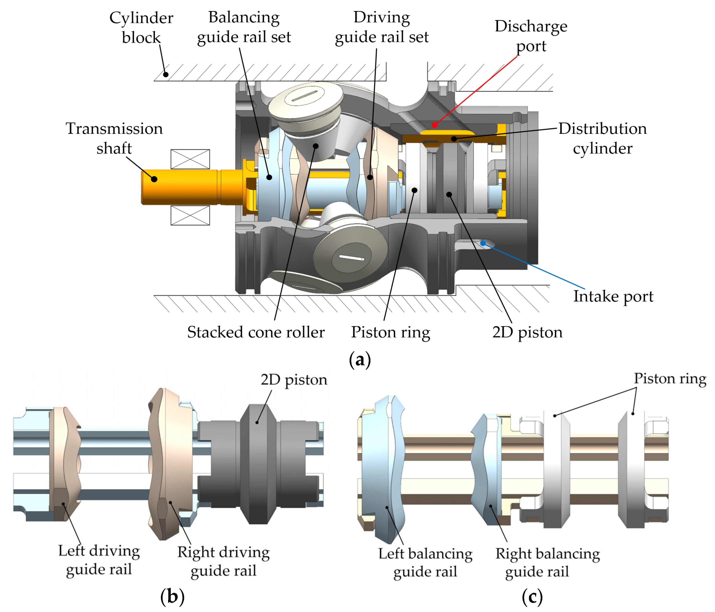
Figure 1a shows the structure of the stacked roller 2D piston pump, which includes a transmission component, oil intake, and a discharge component. The former is composed of a transmission shaft, a stacked cone roller group, a balancing guide rail set, and a driving guide rail set, and the latter is composed of a 2D piston, two piston rings, oil intake and discharge ports, and a distribution cylinder.
Figure 1b demonstrates the driving guide rail set, which includes two clamping shafts and two driving guide rails. The curved surface of the guide rail adopts the law of equal acceleration and equal deceleration, and the specific motion curve is shown in
Figure 2.
Figure 1c illustrates the balancing guide rail set, which includes two clamping shafts and two balancing guide rails. The 2D piston and the piston ring are fixedly connected to the clamping shafts of the driving guide rail set and the clamping shafts of the balancing guide rail set, respectively. The piston ring is set on both sides of the 2D piston to form a closed cavity with the distribution cylinder. The stacked cone roller set of the stacked-roller 2D piston pump is formed by stacking 10 cone rollers in pairs. During working process, the stacked cone roller set closely adheres to the surfaces of the two guiding rail sets by the load pressure to ensure that the working strokes of the 2D piston and piston ring meet the requirements. In addition, the number of strokes can be increased by increasing the number of cone rollers, and the displacement can be raised. The stacked-roller 2D pump sucks and discharges oil 5 times per revolution to further increase the power density.
As shown in
Figure 3a, the oil intake and discharge component mainly includes a distribution cylinder, an oil suction and discharge cavity, a 2D piston, and a piston ring. The distribution cylinder is provided with 10 distribution grooves uniformly distributed in the circumferential direction. The housing includes 5 oil intake ports and 5 oil discharge ports, which are staggered and evenly distributed in the circumferential direction. In the flow distribution process, the distribution grooves communicate alternately with the 10 oil intake and discharge ports to achieve continuous oil intake and discharge.
Figure 3b shows the positional relationship when the ports and the distribution grooves are not communicating, and
Figure 3c shows the positional relationship when communicating.
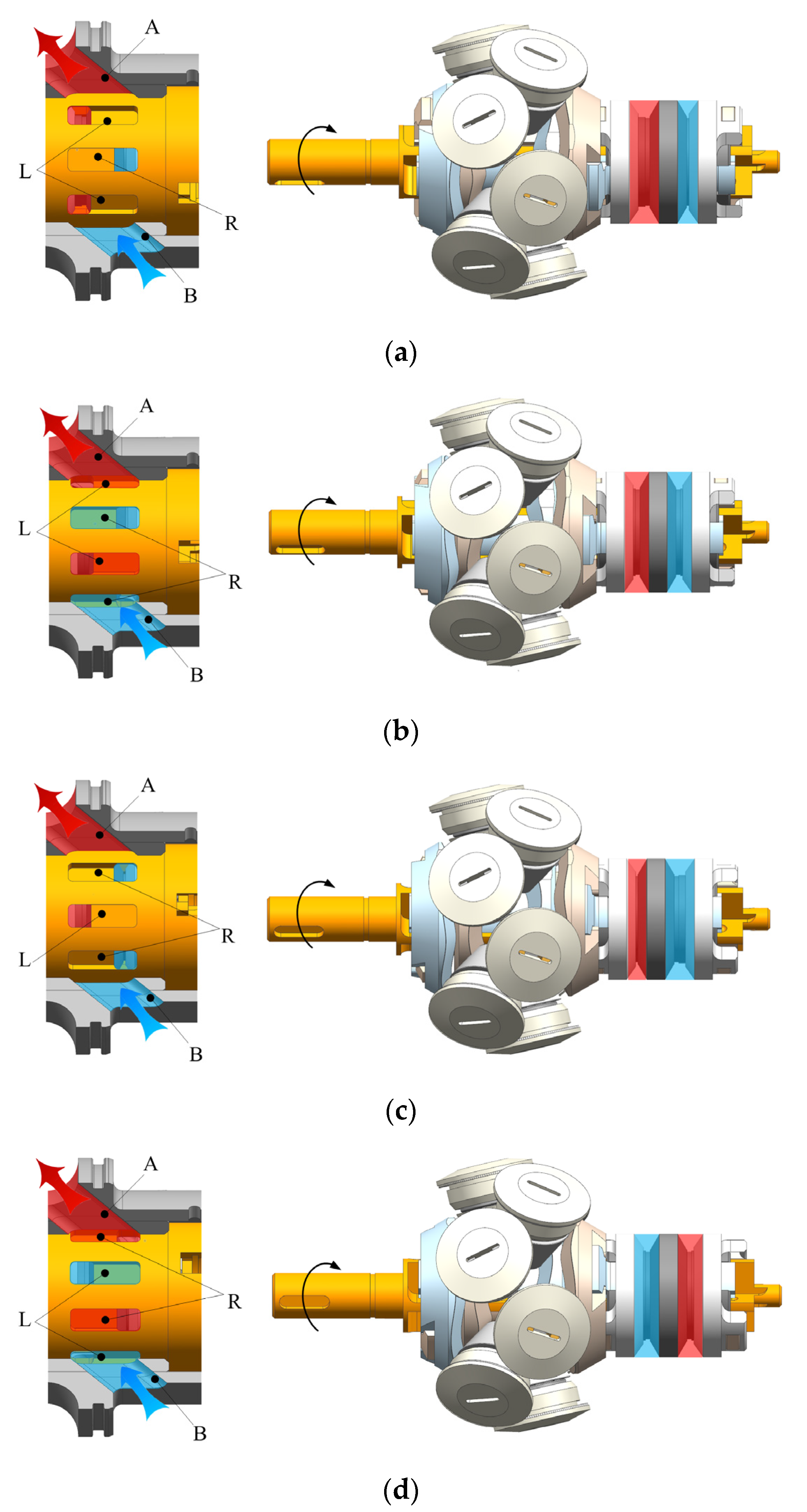
Figure 4 shows the working principle of the stacked roller 2D piston pump. The red and blue represent high-pressure oil and low-pressure oil, respectively. In the working process, the motor drives the clamping shafts to rotate through the transmission shaft, and the driving guide rails and the balancing guide rails rotate synchronously with the clamping shafts. The driving guide rails and the balancing guide rails produce axial reciprocating linear motion under the constraint of the stacked cone roller set, which causes the volume of the enclosed cavity of the 2D piston, the piston ring, and the distribution cylinder to periodically change to achieve oil intake and discharge. In
Figure 4, the discharge port is denoted by A, the intake port is denoted by B, the 5 distribution grooves corresponding to the left cavity are denoted by L, and the 5 distribution grooves corresponding to the right cavity are denoted by R. As shown in
Figure 4a, the rotational angle is 0° at this time, the piston is at the left end and the piston ring is at the right end; thus, the left cavity has the largest volume, and the distribution grooves do not communicate with the oil intake and discharge ports. The process from
Figure 4a to
Figure 4b shows that the 2D piston rotates from 0° to 18°, and the distribution groove L communicates with the discharge port A and starts to drain the oil. At this time, the volume of the left cavity begins to decrease, and the distribution groove R communicates with the intake port B to start sucking oil, and thus, the volume of the right cavity becomes larger. When rotated to 18°, the left and right cavity volumes are equal. In the process from
Figure 4b to
Figure 4c, the left cavity continues to drain oil, and the right cavity continues to suck oil. The communication area between the intake and discharge port and the distribution groove gradually increases until complete communication in the process of
Figure 4a to
Figure 4b, then gradually decreases to not communicate at all in the process of
Figure 4b to
Figure 4c. When it rotates to 36°, the left cavity completes the oil drain function, and the right cavity completes the oil suction function. The left cavity has the largest volume and the right cavity has the smallest volume. The distribution cylinder and the oil intake and discharge ports do not communicate.
In the following 36°, the 2D piston moves to the right, and the volume of the right cavity begins to decrease. The high-pressure oil communicates with the discharge port A through the distribution groove R and drains the oil outward. At the same time, the volume of the left cavity begins to increase, and the low-pressure oil communicates with the oil intake port B through the distribution groove L to suck oil. As shown in
Figure 4c,d, during the process of rotating from 36° to 54°, the communication area between the intake and discharge port and the distribution groove gradually increases until it is completely communicated. Then it gradually decreased to not communication at all in the course of 54° to 72°. When it rotates to 72°, the left cavity completes the oil suction function, and the right cavity completes the oil drain function. The left cavity has the largest volume and the right cavity has the smallest volume, which returns to the state of
Figure 4a. In this process, although the functions of the left and right oil suction and discharge cavity are interchanged, the functions of the intake port and the discharge port do not change. The guide rail set rotates for one cycle, and the stacked roller 2D piston pump sucks and discharges oil five times.
3. Analytical Modeling
Based on the volumetric efficiency of 2D piston pumps with force balanced, the following analysis expands [
30]. Since the working principle of the left and right cavity of the stacked roller 2D piston pump is similar, in this study, the analytical model of the left cavity was analyzed in detail.
Figure 5 shows the maximum volume of the left cavity.
The initial position is the place when the volume of the left cavity is at its maximum. At this position, the left cavity has finished sucking oil and is ready to start discharging oil. Considering the compressibility of the oil, the instantaneous pressure change of the left cavity can be expressed as the following:
where
is the instantaneous pressure of the left cavity,
is the time to rotate a certain angle from 0°,
is the oil bulk modulus,
is the output flow of the left cavity,
is the input flow of the left cavity,
is the leakage of the left cavity, and
is the instantaneous volume of the left cavity.
The instantaneous volume of the left cavity is determined by the positions of the left piston ring and the 2D piston, where the left piston ring and the 2D piston perform equal acceleration and deceleration movements in opposite axial directions. The 2D piston and the piston ring are fixedly connected to the driving guide rail set and the balancing guide rail set, respectively. Therefore, the 2D piston’s speed is the same as the movement speed of the driving guide rail set, and the piston ring’s speed is the same as the movement speed of the balancing guide rail set. The movement speed
of the driving guide rail set and the movement speed
of the balancing guide rail set can be expressed as the following:
where
is the acceleration of the guide rail set movement, which is determined by the rotational speed
;
is the angular velocity of the guide rail set.
When the 2D piston pump rotates from 0° to 18°, the driving guide rail set drives the 2D piston to move to the left with constant acceleration, and the balancing guide rail set drives the piston ring to move to the right as well. The acceleration
can be expressed as the following:
where
is the stroke of the driving guide rail set and the balancing guide rail set, and
is the time required for the driving guide rail set to rotate from 0° to 18°.
The instantaneous volume
of the left cavity can be expressed as the following:
where
is the maximum volume of the left cavity, and
is the effective working area of the piston and piston ring,
represents the time required for the driving rail set to rotate from 0° to 18°, from 18° to 36°, from 36° to 54°, and from 54° to 72°, respectively. Derivative of Formula (4), it yields:
where
represents the time required for the driving rail set to rotate from 0° to 18°, from 18° to 54°, and from 54° to 72°, respectively.
The input flow
and output flow
of the left cavity can be expressed by the following standard orifice plate formula:
where
is the flow rate coefficient,
and
form the communication area between the distribution grooves and the intake and discharge ports,
is the tank pressure,
is the load pressure, and
is the oil density.
As shown in
Figure 6, the leakage
of the 2D piston pump mainly includes internal leakage
and external leakage
. The internal leakage
includes the axial internal leakage
generated by the gap between the outer wall of the piston and the distribution cylinder, and the circumferential internal leakage
generated by the gap between the distribution cylinder and the housing. External leakage
includes
,
, and
. Among them,
is the leakage of high-pressure oil through the gap between the outer wall of the piston rod and the inner wall of the piston ring.
is the leakage of the gap between the outer wall of the piston ring and the inner wall of the distribution cylinder.
is the leakage between the outer wall of the distribution cylinder and the inner wall of the housing.
and
are caused by Couette–Poiseuille flow.
is only caused by Poiseuille flow. The external leakage
,
, and
can be expressed as the following:
where
is the pressure difference between the two sides of the piston ring,
is the diameter of the piston rod,
is the diameter of the 2D piston,
is the outer diameter of the distribution cylinder, and
is the oil dynamic viscosity.
is the contact length between the outer wall of the piston ring and the inner wall of the distribution cylinder.
is the contact length between the outer wall of the piston rod and the inner wall of the piston ring.
is the minimum distance between the distribution cylinder groove and one side of the roller.
is the minimum distance between the distribution cylinder groove and the intake port.
is the width of the gap.
The contact length
can be expressed as the following:
where
is the minimum contact length between the inner wall of the piston ring and the outer wall of the piston rod.
The internal leakage
can be expressed as the following:
where
is the pressure difference on both sides of the piston, and
is the width of the piston.
As shown in
Figure 7, the circumferential contact length
between the outer wall of the distribution cylinder and the inner wall of the housing changes with the rotational angle.
Figure 7a–c are the lengths of
when the rotational angle is 0°, 9°, and 18°, respectively. The change of
can be expressed as the following:
When the distribution cylinder is rotated at 0°,
is 0, and the distribution groove of the distribution cylinder does not communicate with the oil suction and discharge port. At this time, the leakage can be represented by the sharped-edged orifices leakage model, as shown in
Figure 7a. When the distribution groove and the suction and discharge port gradually communicate, as shown in
Figure 7b,c, the leakage of the process can be represented by the gap leakage model. Therefore, the circumferential leakage can be expressed as the following:
The oil suction communication area
and the oil discharge communication area
of the 2D piston pump can be expressed as the following:
Finally, in the process of discharging the oil from the left cavity, the discharge flow is obtained by integrating the output flow and then compared with the theoretical discharge flow. The volumetric efficiency of the stacked roller 2D pump can be expressed as the following:
where
is the time required for the 2D pump to rotate from 0° to 36°,
is the displacement of the 2D piston pump, and
n is the rotational speed.
4. Co-Simulation by Simulink and AMESim
In order to verify the volumetric efficiency of the stacked roller 2D piston pump, a co-simulation model of the pump was established by using Simulink and AMESim software, as shown in
Figure 8. The relationship between the pump outlet flow, leakage flow, load pressure, and speed was simulated. The internal circumferential leakage model
of the pump was divided into two forms. The sharped-edged orifice leakage was simulated with a fixed opening orifice, and the gap leakage with varying gap length was simulated with the equivalent flat plate leakage. The circumferential contact length
is related to the electrical motor rotational angle and the axial contact length
of the external axial leakage
of the piston ring is related to the displacement of the piston ring. Since the existing leakage sub-model was not available, it was necessary to create an interface module in combination with the analytical model described in
Section 3. Then, the communication state between the distribution groove and the intake and discharge port calculated by Simulink was transferred to the AMESim model to complete the equivalent analysis.
Figure 9 shows the Simulink interface module. The input signals included the electrical motor rotational angle (theta_1, theta_2), the piston ring displacement (dis_1), the leakage flow of the constant-length plate (flow_1, flow_3), and the throttle leakage flow (flow_2, flow_4). The output signal included the load pressure (Pressure), the electric motor speed (Rotation), the circumferential leakage flow (Cir_1, Cir_2), the piston ring axial gap length (Axi_1, Axi_2), the 2D conversion coefficient (Signal_1, Signal_2), and the flow distribution communication area (SA_1, SA_2).
Table 1 shows the simulation parameter settings of the co-simulation model.
The stacked roller 2D piston pump realizes the movement of the piston with 2° of freedom through the guide roller structure. Therefore, it was necessary to convert the rotation of the transmission shaft into the axial reciprocating movement of the 2D piston so as to realize the suction and discharge of the oil. The electrical motor drives the 2D piston to rotate at angular velocity
ω, which is converted into the linear velocity
of the 2D piston through a 2D conversion module. The conversion relationship between
ω and
can be expressed as the following:
where
is the linear motion speed of the 2D piston, as described in Formula (2),
ω is the angular velocity of the 2D piston, and
is the conversion coefficient,
is the input signal, which sets the change ratio of
and
ω.
The conversion coefficient
obtained by Formula (2) can be expressed as the following:
There are 5 oil suction windows and 5 oil discharge windows in the 2D pump to complete the suction and discharge action at the same time. In the AMESim software, 5 adjustable orifices were used to simulate the oil suction window and the oil discharge window, and the opening of the throttle was adjusted to correspond to the changing state of the distribution area of the 2D piston pump when intaking and discharging oil. The left cavity was taken as an example to illustrate the change of the distribution area. The communication area between the left cavity and the oil intake and discharge port is shown in Formulas (15) and (16). The oil suction window and oil discharge window built with the orifice are shown in
Figure 10a,b, respectively.
Taking the left cavity as an example,
Figure 11 and
Figure 12 are the output flow curves of the left cavity under different loads and rotational speeds. When the suction of the left cavity is finished, the oil will be discharged immediately. During the transition of suction and discharge, the instantaneous pressure of the left cavity is less than the load pressure. When the distribution groove communicates with the discharge port, the oil will flow back into the left cavity.
Figure 11 shows the change curve of the output flow with a speed of 6000 rpm and load pressures of 2 MPa, 5 MPa, and 8 MPa, respectively. It can be seen from
Figure 11a that the output flow increases linearly and then decreases linearly with the increase of the rotational angle. As shown in
Figure 11b, when the rotational speed is constant, the peak value and the duration of the backflow rise with the increase of the load pressure. As the load pressure increases, the pressure difference between the instantaneous pressure of the left cavity and the load pressure will also rise, so the backflow will lead to the instantaneous pressure of the left cavity to increase to the level of system pressure, and then the left cavity transfers to a discharge oil state.
Figure 12 shows the change curve of the output flow with a load pressure of 5 MPa and rotational speeds of 2000 rpm, 4000 rpm, and 6000 rpm, respectively. It can be seen from
Figure 12a that the output flow rises linearly and then declines linearly with the increase of the rotational angle, and the output flow rises with the increase of speed.
Figure 12b shows the change curve of the backflow. When the load pressure is 5 MPa, the peak value of the backflow increases with the increase of the rotational speed, but the backflow duration decreases. Since the load pressure is constant and the total demand for the backflow is unchanged, and the duration decreases due to the flow peak increases.
Figure 13 shows the change curve of
under different load pressures and rotational speeds. When the left cavity starts to drain oil, the pressure in the cavity is less than the load pressure. At this time, the backflow leads to an increase in the pressure in the left cavity, and the peak value of the external axial leakage appears.
Figure 13a shows the change curve of
with a speed of 6000 rpm and load pressures of 2 MPa, 5 MPa, and 8 MPa, respectively. When the left cavity starts to drain oil,
is caused by the Couette–Poiseuille flow, and the direction of the Poiseuille flow is opposite to the direction of the Couette flow. As the
and
increase, the leakage caused by the Poiseuille flow decreases, the leakage caused by the Couette flow increases, and, therefore, the
decreases according to Formula (7).
is only caused by the Couette flow in the state of oil absorption, and it declines with the decrease of the
. Therefore,
increases according to Formula (7).
Figure 13b shows the change curve of
with a load pressure of 5 MPa and rotational speeds of 2000 rpm, 4000 rpm, and 6000 rpm, respectively. The changing trend is consistent with
Figure 13a. However, as the rotational speed increases, the leakage caused by the Couette flow rises. Therefore, in the oil discharge stage,
increases with the decrease of the rotational speed; during the oil suction stage,
rises with the increase in the rotational speed.
Figure 14 shows the change curve of the sum of
and
under different load pressures and rotational speeds.
Figure 14a is the change curve of the sum of
and
with a rotational speed of 6000 rpm and load pressures of 2 MPa, 5 MPa, and 8 MPa, respectively.
is similar to
, except that the contact length
is constant, and therefore,
changes linearly. Therefore, the sum of
and
also changes linearly with the change of the rotational angle.
Figure 14b shows the variation curve of
and
with a load pressure of 5 MPa and rotational speeds of 2000 rpm, 4000 rpm, and 6000 rpm, respectively. When the pressure is 5 MPa, the leakage caused by the Couette flow rises with the increase of the rotational speed. In the oil discharge stage,
increases with the decrease of the rotational speed, while
remains unchanged; therefore, the sum of
and
increases with the decrease of the rotational speed. In the oil suction stage, the sum of
and
rises with the increase of the rotational speed.
Figure 15 shows the variation curve of
under different load pressures and rotational speeds.
Figure 15a shows the change curve of
with a rotational speed of 6000 rpm and load pressures of 2 MPa, 5 MPa, and 8 MPa, respectively.
is caused by the Couette–Poiseuille flow in the oil suction and discharge stage. Since the contact length
is constant,
changes linearly with the increase of the rotational angle. When the oil is discharged from the left cavity,
increases and then decreases with the increase of the rotational angle. The variation of the leakage caused by the Couette flow is positively correlated with
and, therefore,
decreases and then increases during the oil discharge stage.
Figure 15b shows the change curve of
with a load pressure of 5 MPa and rotational speeds of 2000 rpm, 4000 rpm, and 6000 rpm, respectively. When the pressure is 5 MPa, the leakage caused by the Couette flow rises with the increase of the rotational speed. In the oil discharge phase,
decreases with the increase of the rotational speed; in the oil suction phase,
rises with the increase of the rotational speed.
Figure 16 shows the change curve of
under different load pressures and rotational speeds. It can be seen that when it rotates to 0°, 36°, and 72°, the leakage flow has instantaneous peak values. At these positions, the distribution groove is completely out of communication with the oil suction and discharge ports. Since the seal between the distribution cylinder and the housing changes from the original face seal to the line seal, it can be regarded as sharp-edged orifice leakage, and its instantaneous leakage rises with the increase of the pressure difference.
Figure 16a shows the variation curve of
with a rotational speed of 6000 rpm and load pressures of 2 MPa, 5 MPa, and 8 MPa, respectively. When the rotational speed is 6000 rpm, the pressure difference between the left cavity and the fuel tank increases with the increasing load pressure, which results in the increase of the instantaneous leakage.
Figure 16b shows the variation curve of
with a load pressure of 5 MPa and rotational speeds of 2000 rpm, 4000 rpm, and 6000 rpm, respectively. When the load pressure is 5 MPa, the circumferential leakage does not change significantly with the increase in speed.


