

Protocol for Converting DICOM Files to STL Models Using 3D Slicer and Ultimaker Cura
 , ,
, ,  and
and 
Abstract
1. Introduction
2. Protocol Description
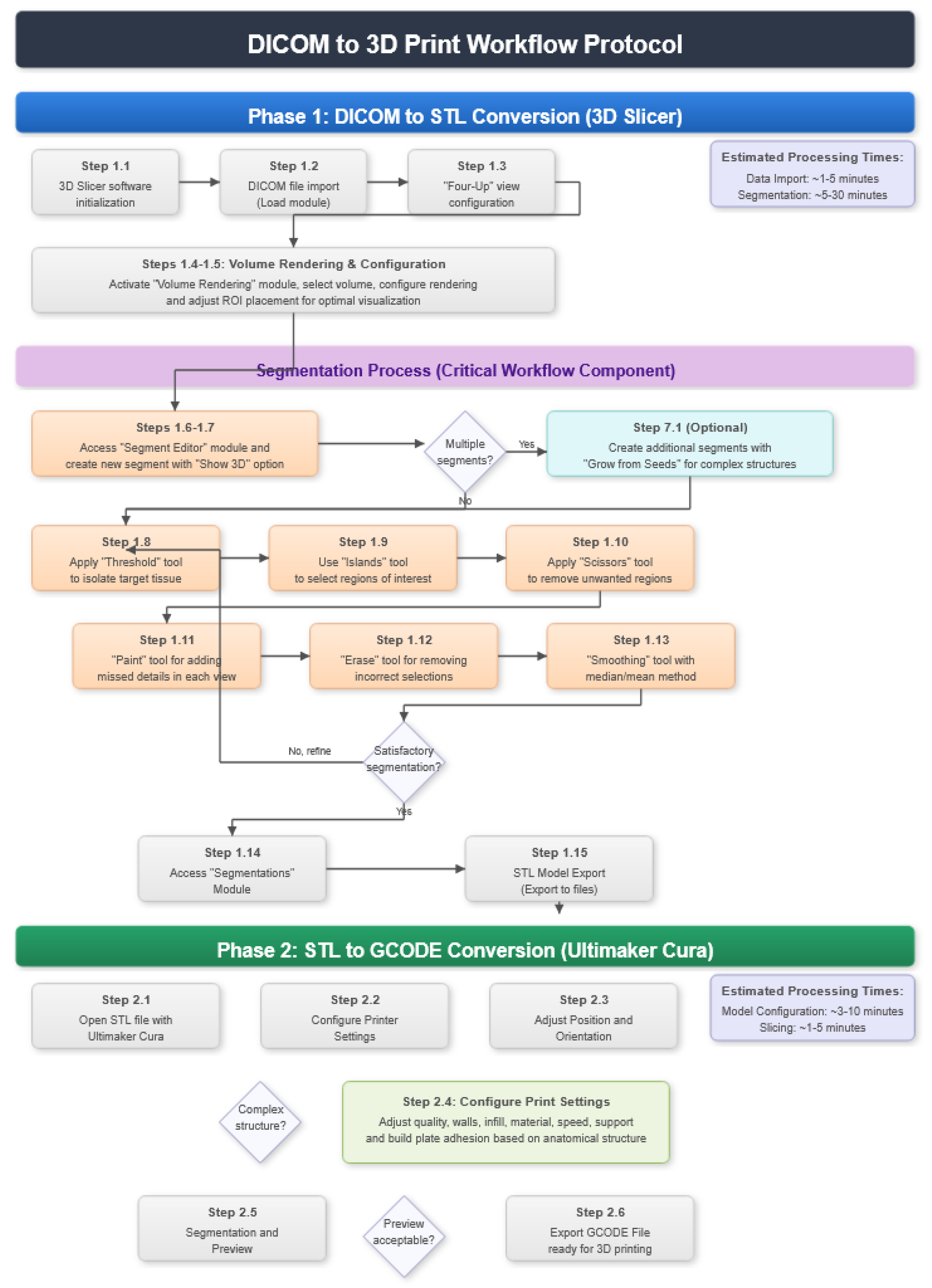
2.1. DICOM-to-STL File Conversion
- At the DICOM module, select “Load” in order to import the corresponding DICOM file for the medical image of interest.
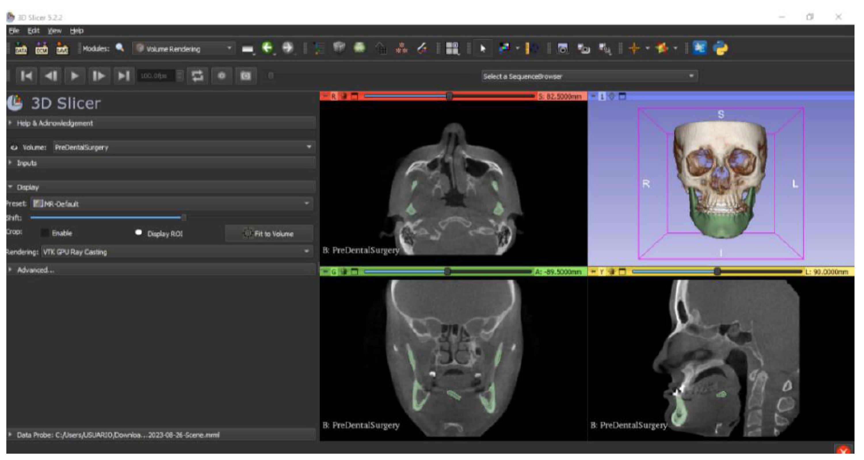
- Go to the “Layout Selection” in the tool bar, and select “Four-Up” view. This configuration allows for the visualisation of DICOM images in three different views, along the 3D view.
- Select the “Volume Rendering” module in the toolbar.
- Select the volume of interest in the drop-down menu, and activate the rendering function.
- Configure the rendering process by accessing the “Display” drop-down. Choose the most appropriate “preset” option in terms of the image and anatomical model tissue.
- Use the Shift function to adjust the rendered visible tissues, and enable the “Crop” option in order to cut the “region of interest”.
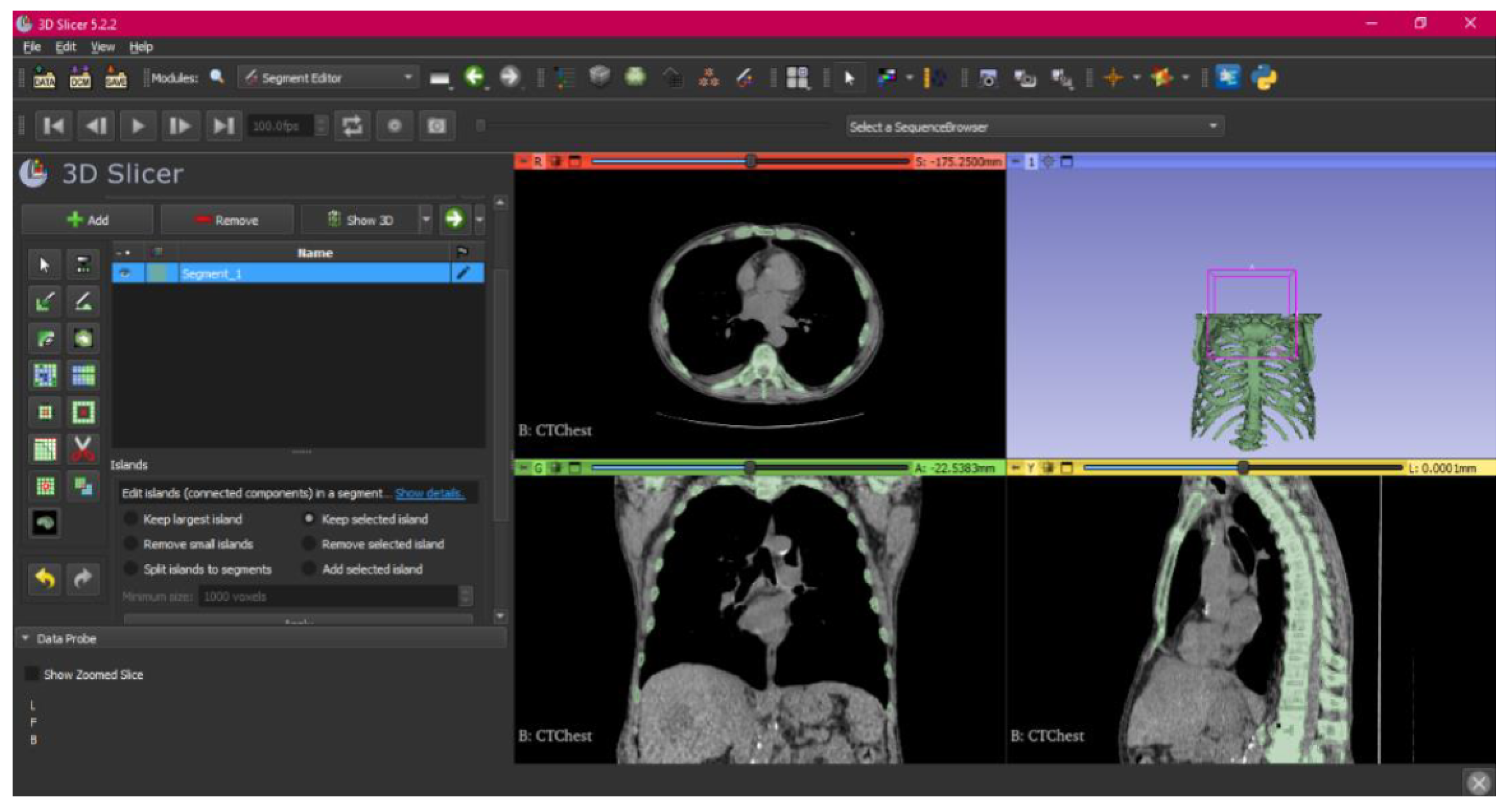
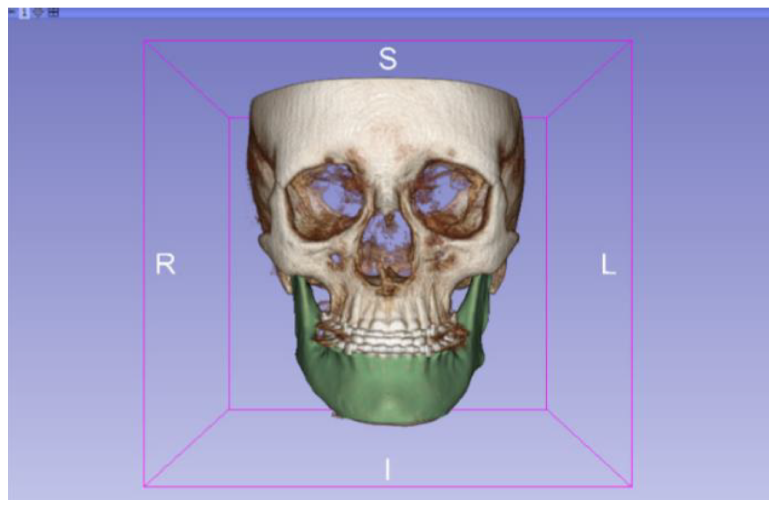
- Make the Region of Interest (ROI) display visible in order to visualise it, and adjust the ROI volume rendering square in the region of interest for the 3D view.
- Go to the “Segment Editor” module in the toolbar.
- Select “Add new empty segment”, and assign a descriptive name to the segment.
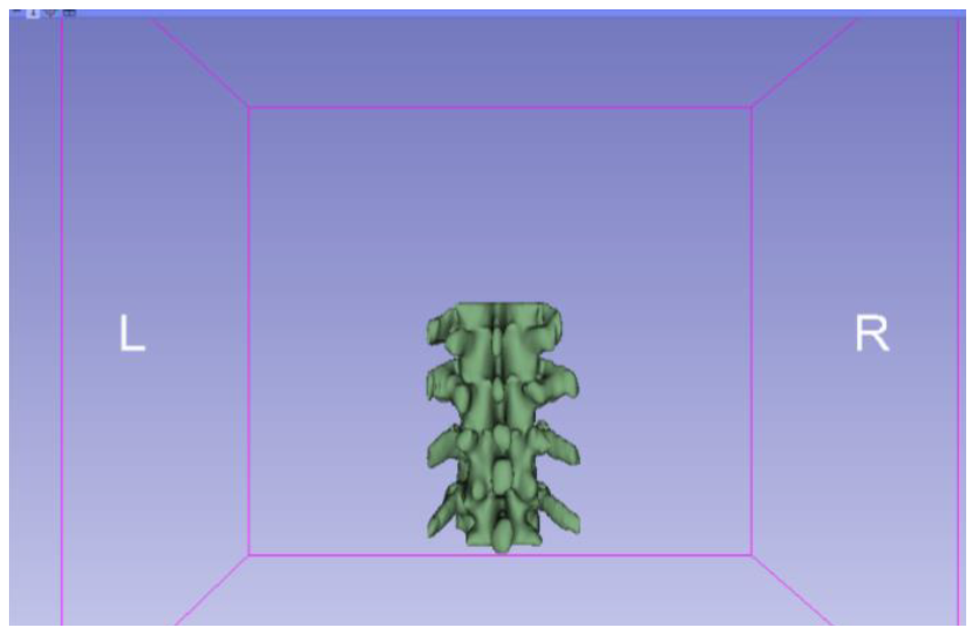
- Press “Show 3D” to visualise the segment in the corresponding 3D View.
- Creation of new segments: Start the creation of additional segments for the corresponding structures.
- “Grow from Seeds” tool: Select the “Grow from Seeds” tool for a more detailed segmentation.
- Seed placement: Identify and select reference points or seeds inside the regions to be segmented.
- Initiate the segmentation process: Activate the “Grow from Seeds” function, and allow the tool to expand the segmentation from the seeds to the adjacent regions.
- Select “Threshold” tool.
- Adjust the threshold of the Threshold range until it includes the entire region of interest, and apply the settings.
- Use the “Islands” tool.
- Select the “Keep selected islands” option, and mark the areas of interest in one of the views.
- Select the “Scissors” tool.
- Configure the options “Erase inside”, “Free-form’,’ and “Unlimited”.
- In the views, select and delete unwanted parts until the desired anatomical structure is obtained.
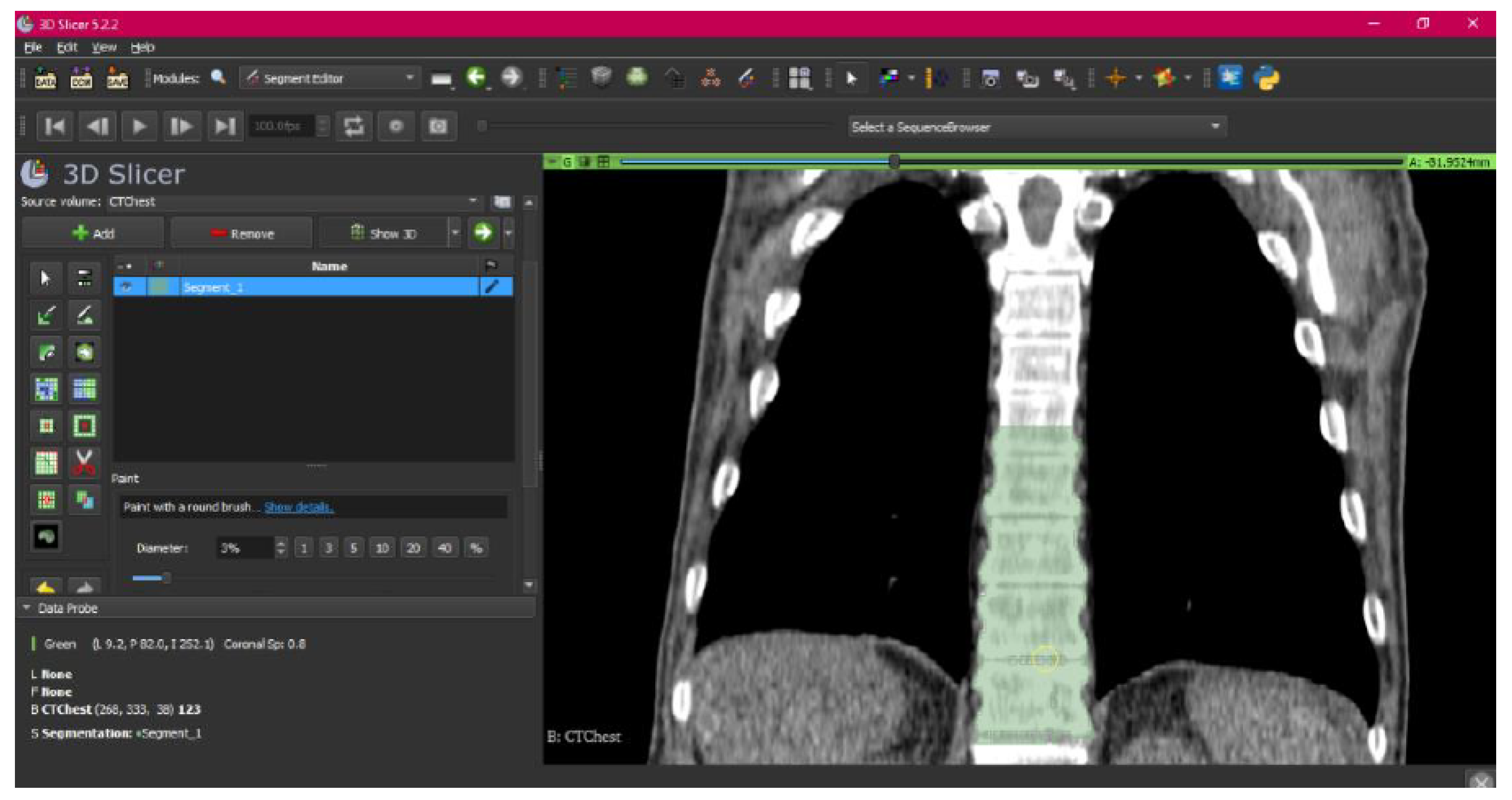
- Use the “Paint” tool.
- Paint those parts which have not been selected yet and which form part of the model for each one of the “cuts” of the three views.
- Use the “Erase” tool.
- Paint the selected parts, which do not form part of the model for each cut in the three views.
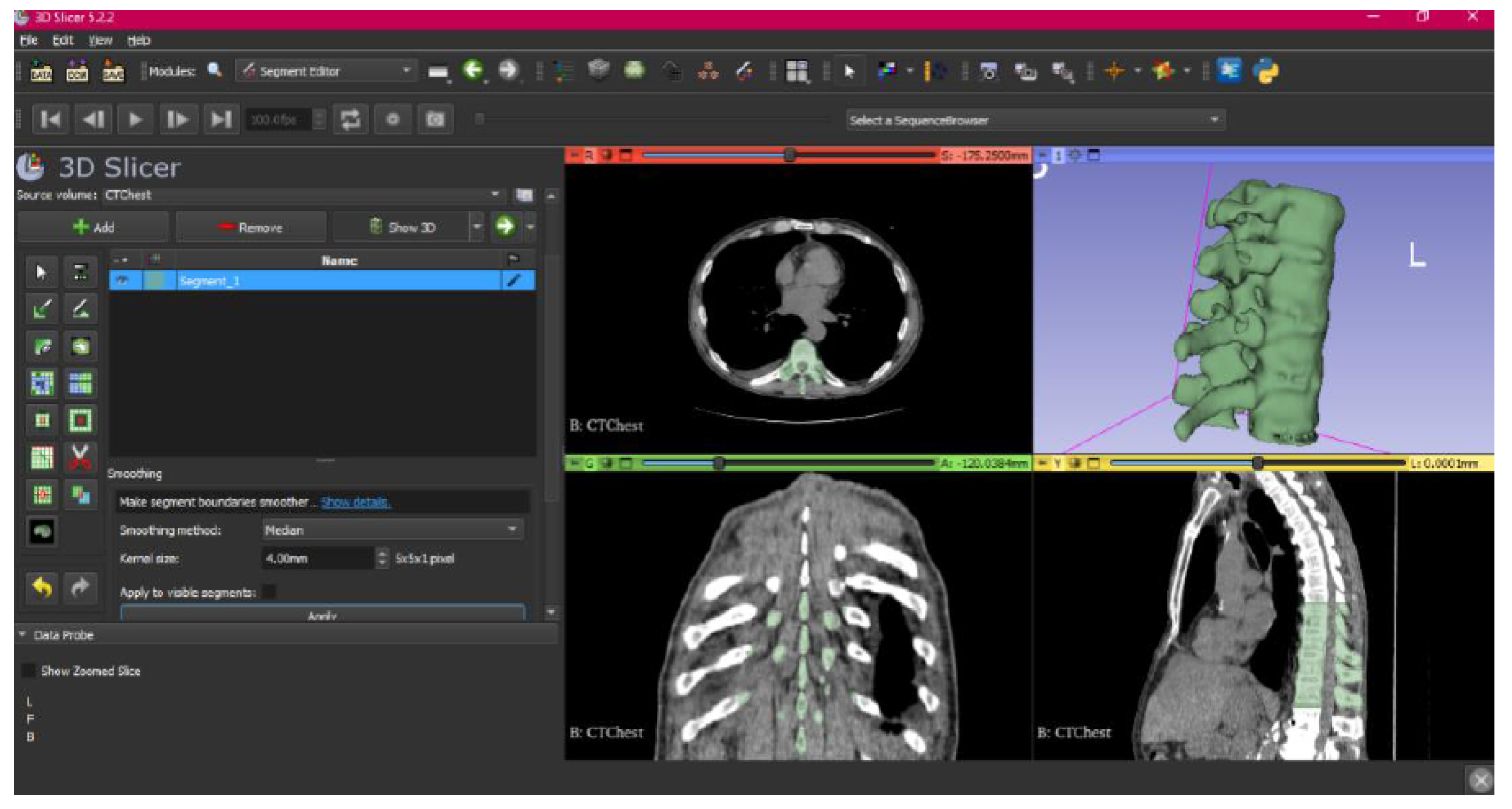
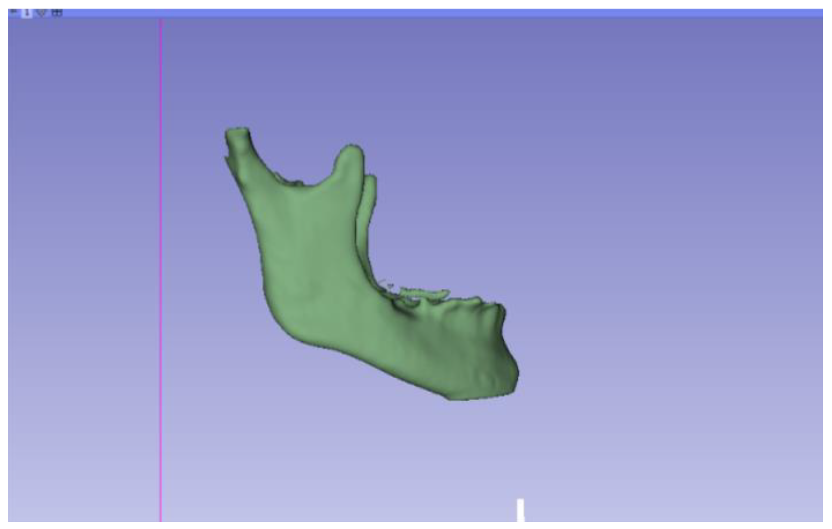
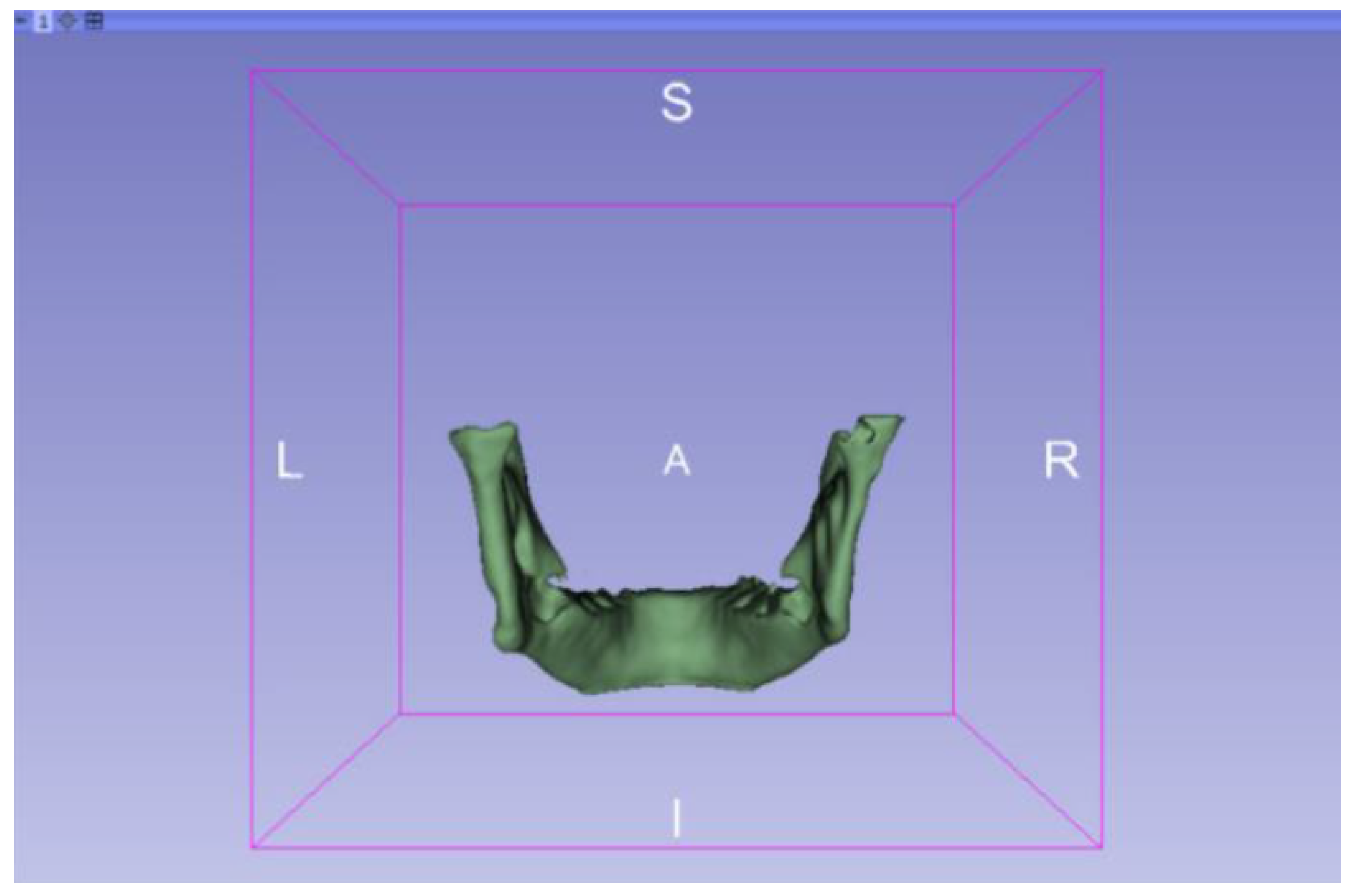
- Select the “Smoothing” tool.
- Choose the “median” or “mean” method, and configure the kernel size as needed.
- Go to the “Segmentations” Module in the toolbar.
- Go to “Export/import models and label maps”.
- In the menu, select “model” as the output option.
- In “Export to files”, choose the destination folder.
- Select the STL file format, and, finally, click on “Export”.
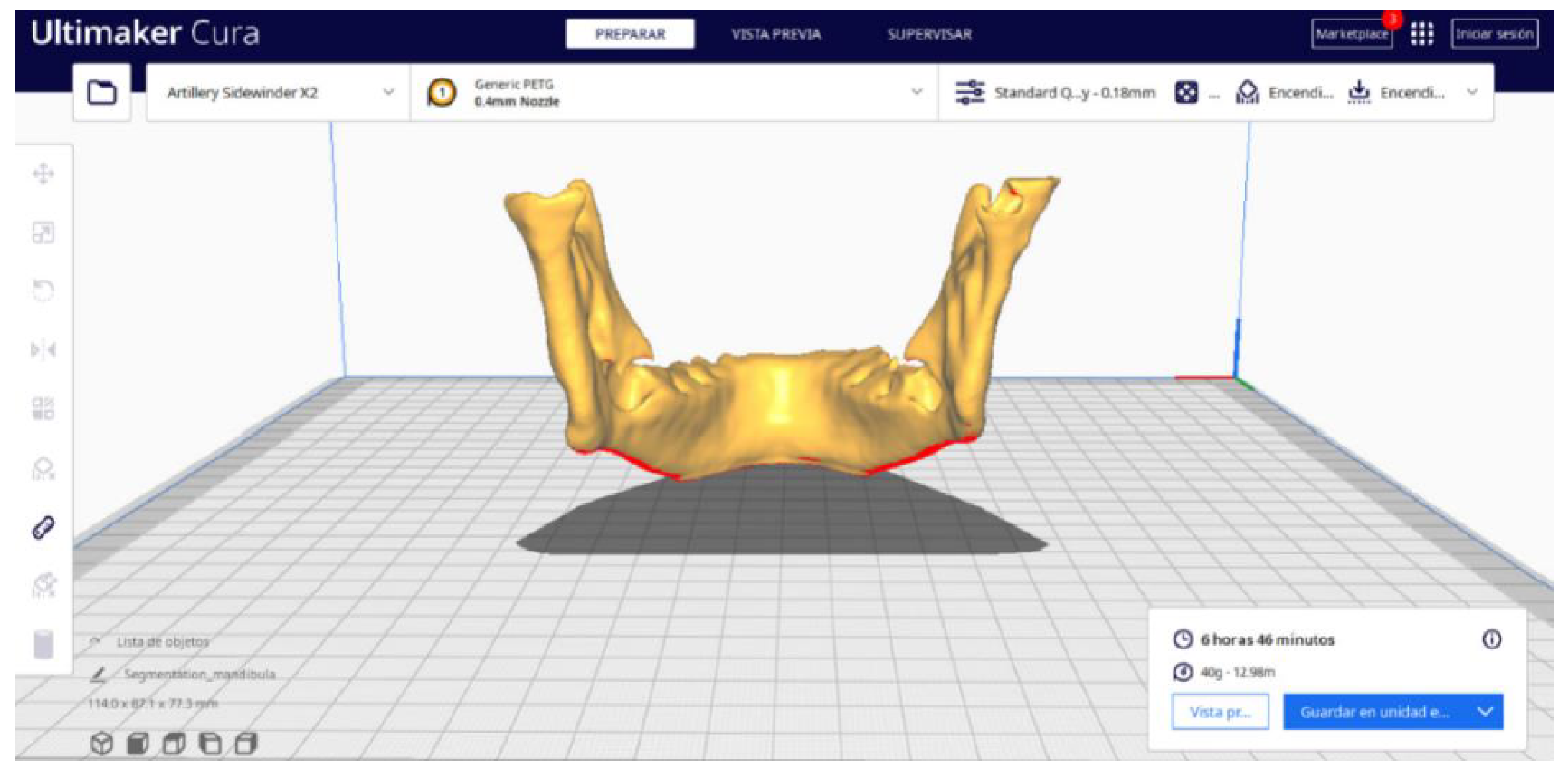
2.2. STL-to-GCODE File Conversion
- Launch the Ultimaker Cura program on your computer.
- Open the STL file you want to print from the “Open File” option in the menu.
- Access the printer settings within Ultimaker Cura.
- Be sure to select the appropriate printer model and material settings for your 3D printer.
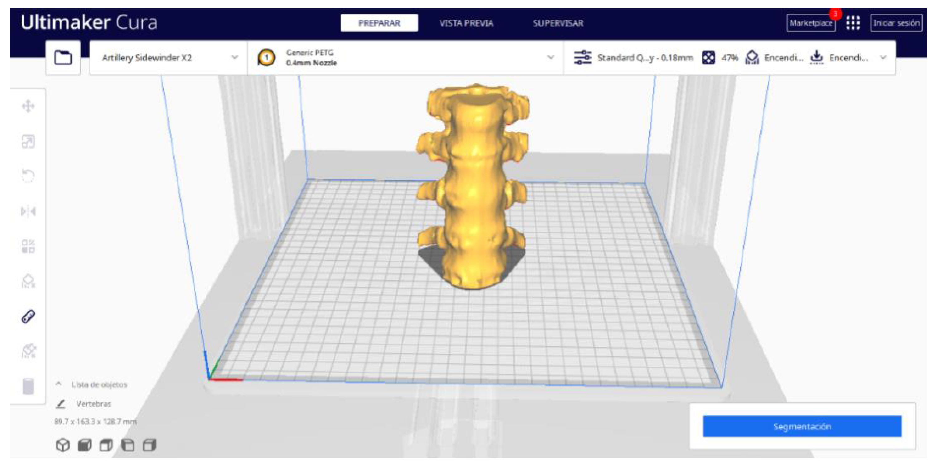
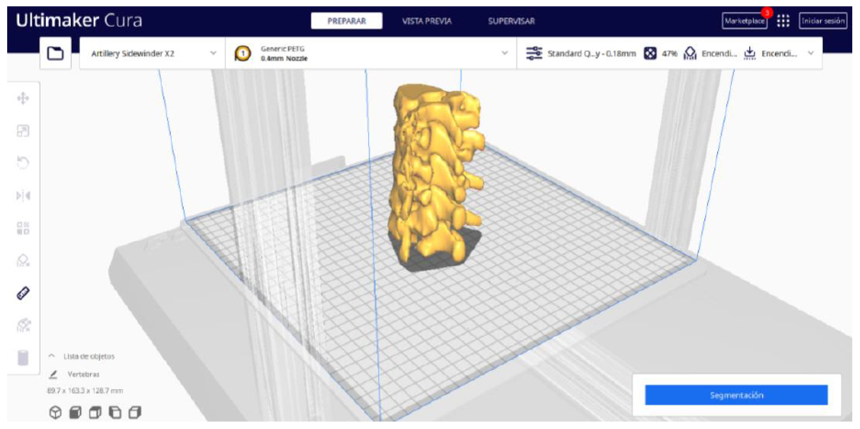
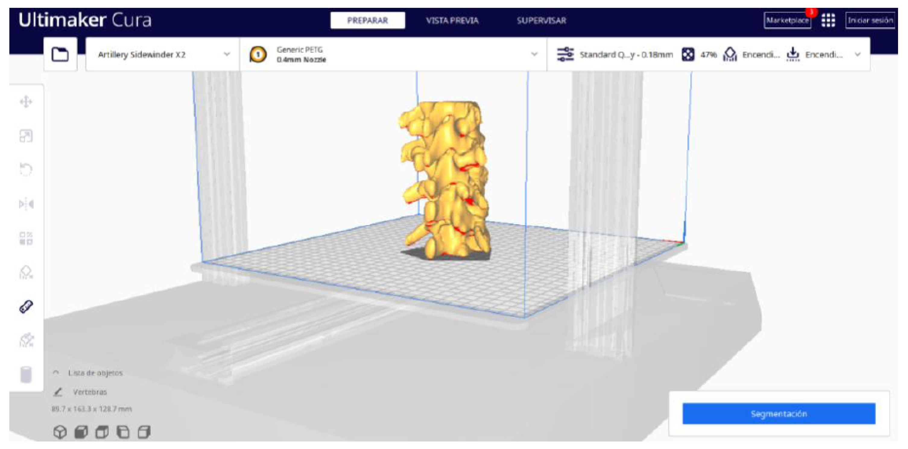
- If necessary, make adjustments to the position, scale, or rotation of the model on the build platform within Ultimaker Cura. This allows you to optimise the layout of the model on the printing platform.
- Adjust the layer height and line width to refine the print quality, considering the balance between print resolution and time efficiency.
- The print quality can be improved by increasing the number of walls, which strengthens the structure and improves the surface final result. Adjust the wall line count and interior-to-exterior orientation to optimise for strength and aesthetics.
- Set the number of top and bottom layers, select a pattern for these surfaces, and enable flattening with a specific pattern if necessary. These adjustments influence the surface texture and structural integrity of the printed object.
- Determine the density and pattern of the infill, taking into account the trade-off between the weight of the object and its structural robustness. The fill-in sequence in relation to the wall print can also affect the final quality of the print.
- Set the print temperature, initial layer temperature, final temperature, and build plate temperature according to the filament material specifications to ensure optimal extrusion and adhesion. The flow rate may also need adjustment to achieve the desired extrusion quality. It is crucial to refer to the filament manufacturer’s guidelines for specific settings, as these can vary significantly between different materials and brands.
- Control the print speed to balance the print quality and time efficiency. Slower speeds typically result in higher-quality prints by allowing for more precise material deposition.
- Enable retraction to prevent dripping and threading by adjusting the distance and speed of retraction based on the printer capabilities and filament used.
- Adjust the fan speed to regulate cooling, which can significantly affect the print quality, especially on overhangs and bridges. It is important to note that the optimal cooling configuration will vary depending on the printing material used since each material has different thermal properties that affect its behavior against rapid cooling.
- Choose the appropriate support structure type and pattern to ensure the successful printing of complex geometries, adjusting the adhesion to the build plate as necessary.
- Select an adhesion type to improve the first coat’s adhesion to the build plate, reducing problems associated with poor first coat adhesion.
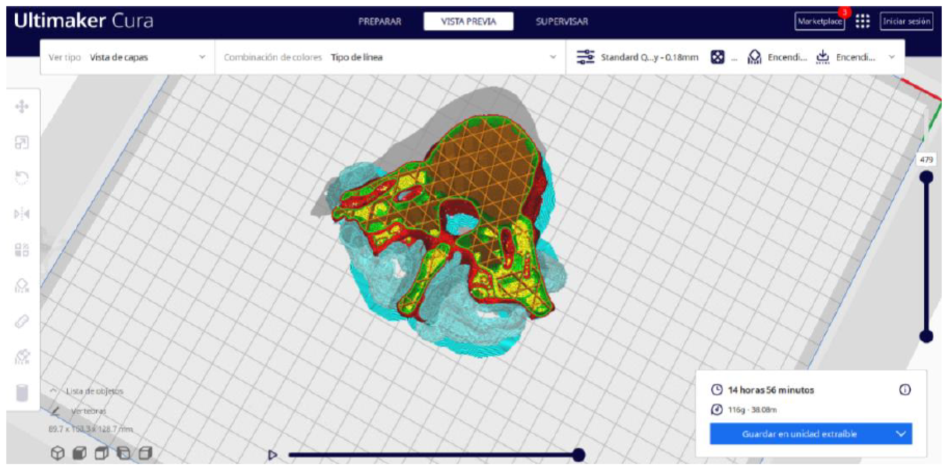
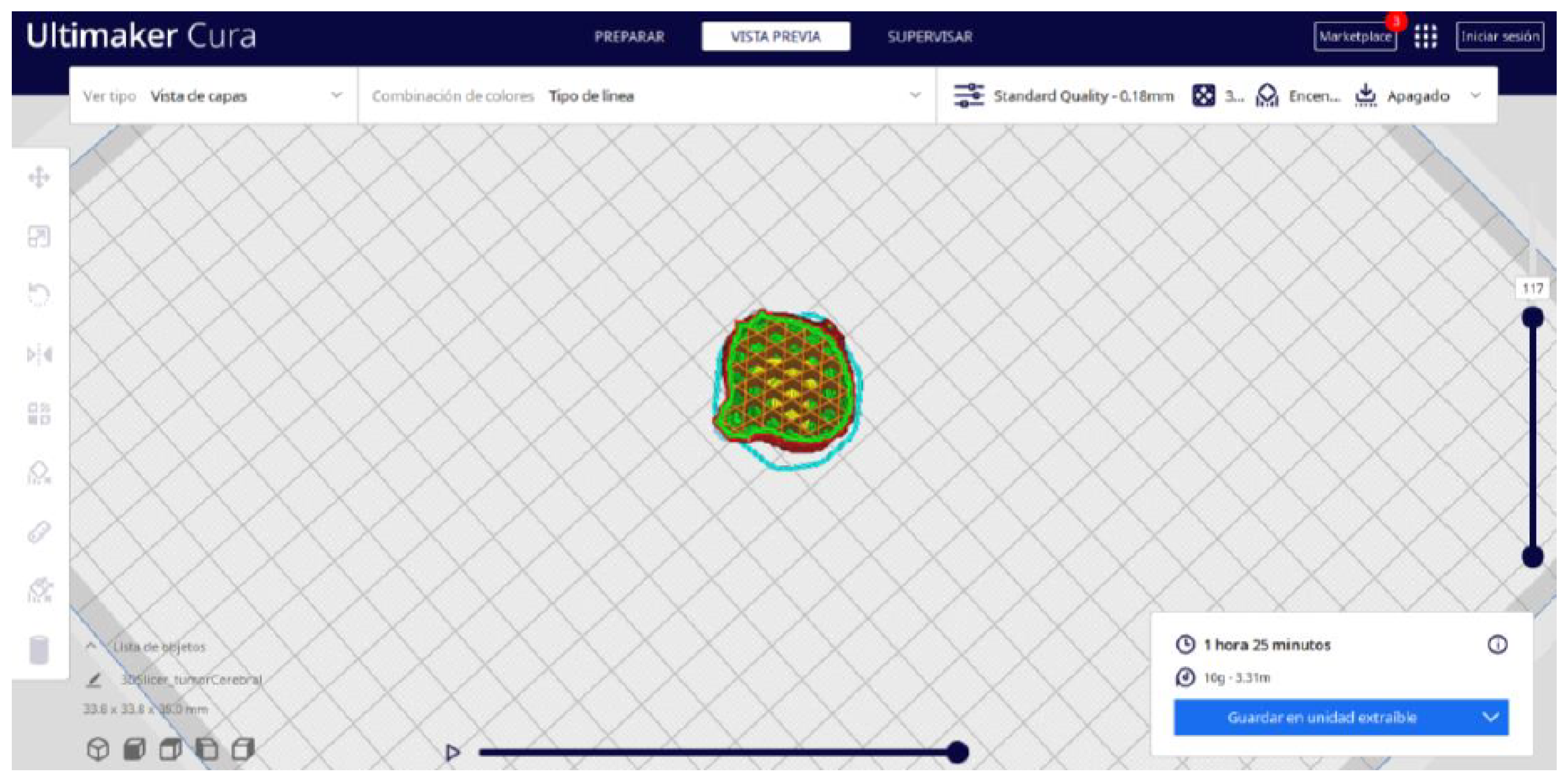
- In order to continue the STL file to GCODE conversion process, select the “Segmentation” option in Ultimaker Cura.
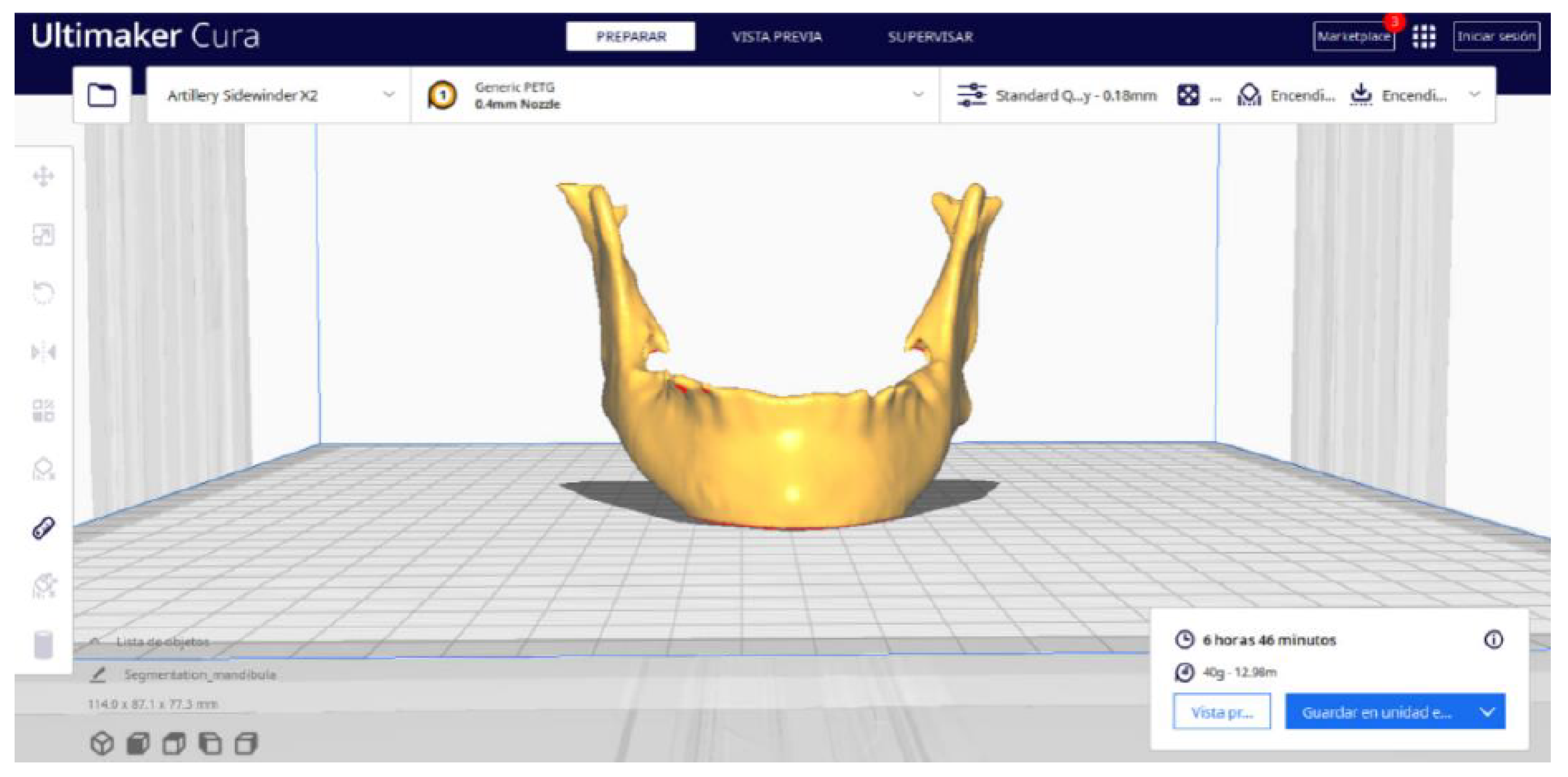
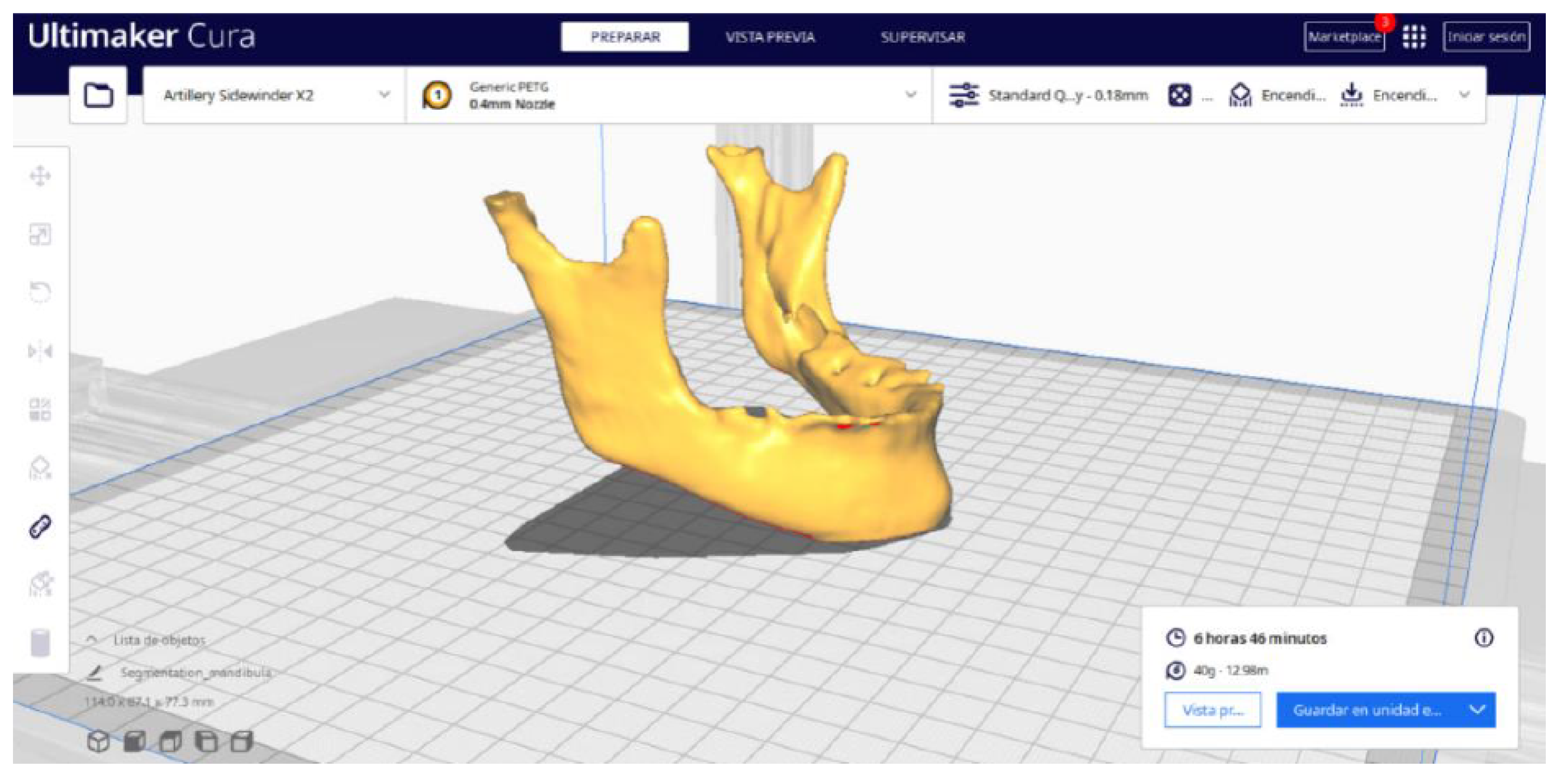
- The segmentation tool provides valuable information such as the estimated model weight and estimated printing time, among other crucial data.
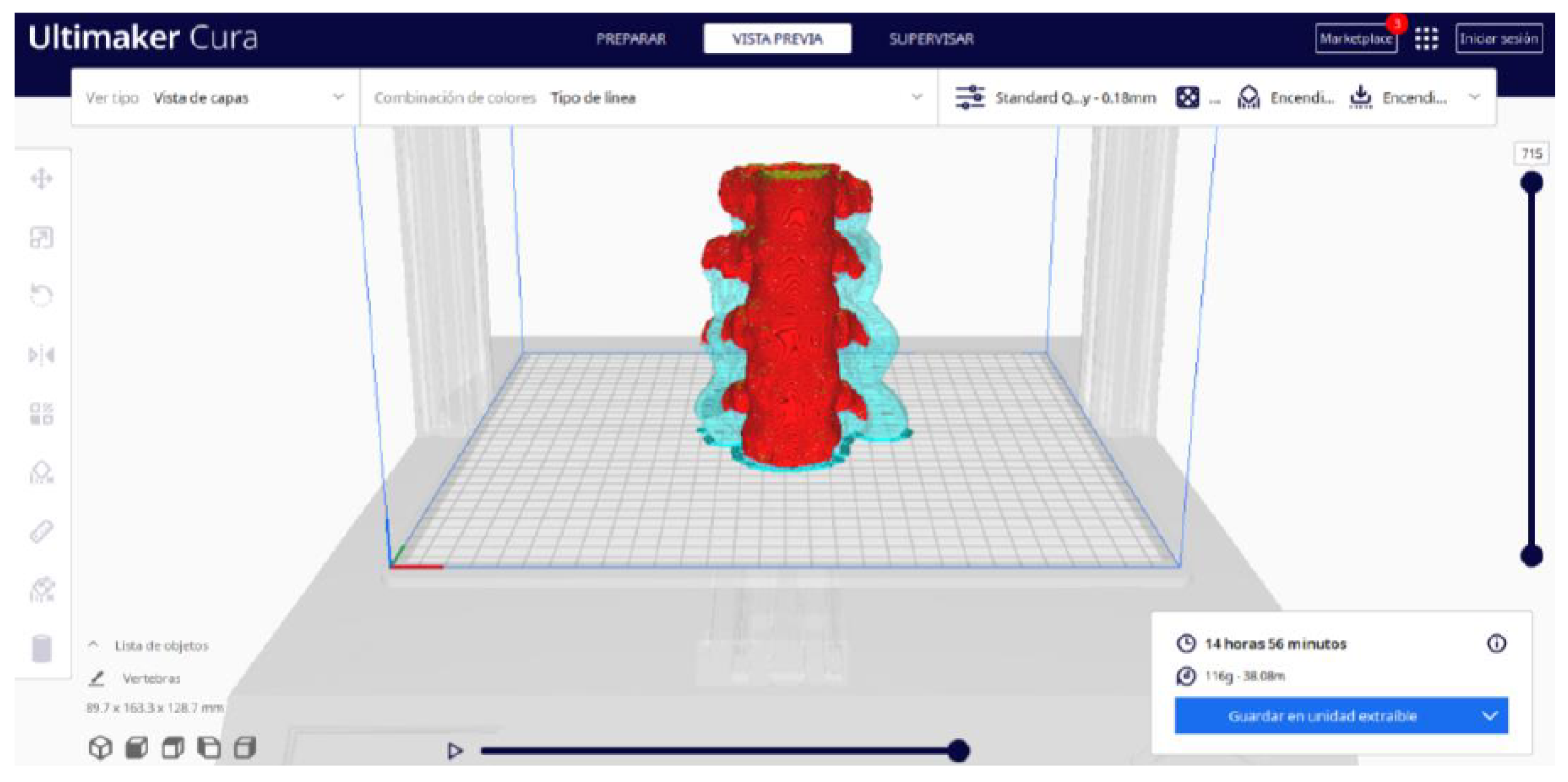
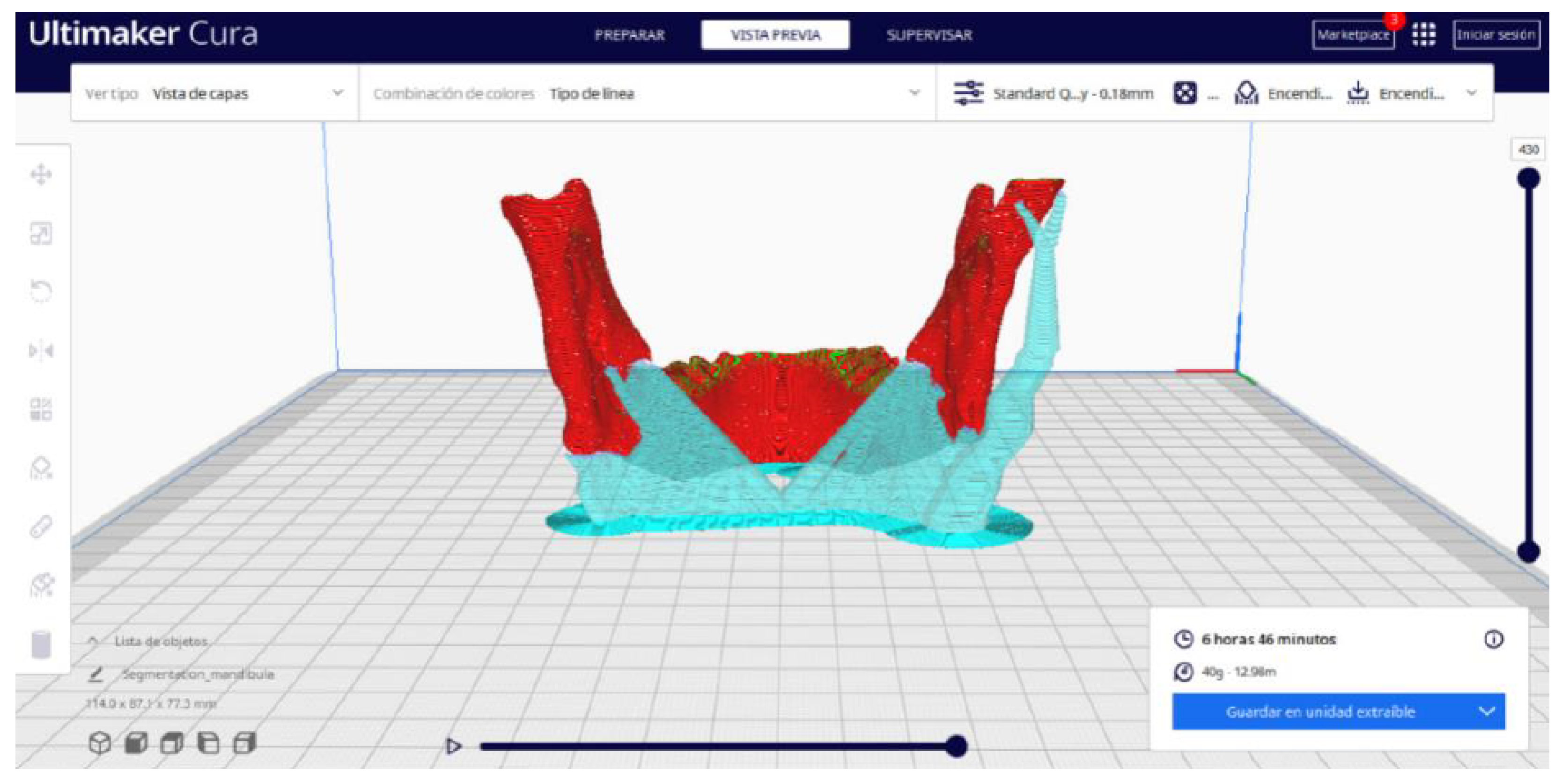
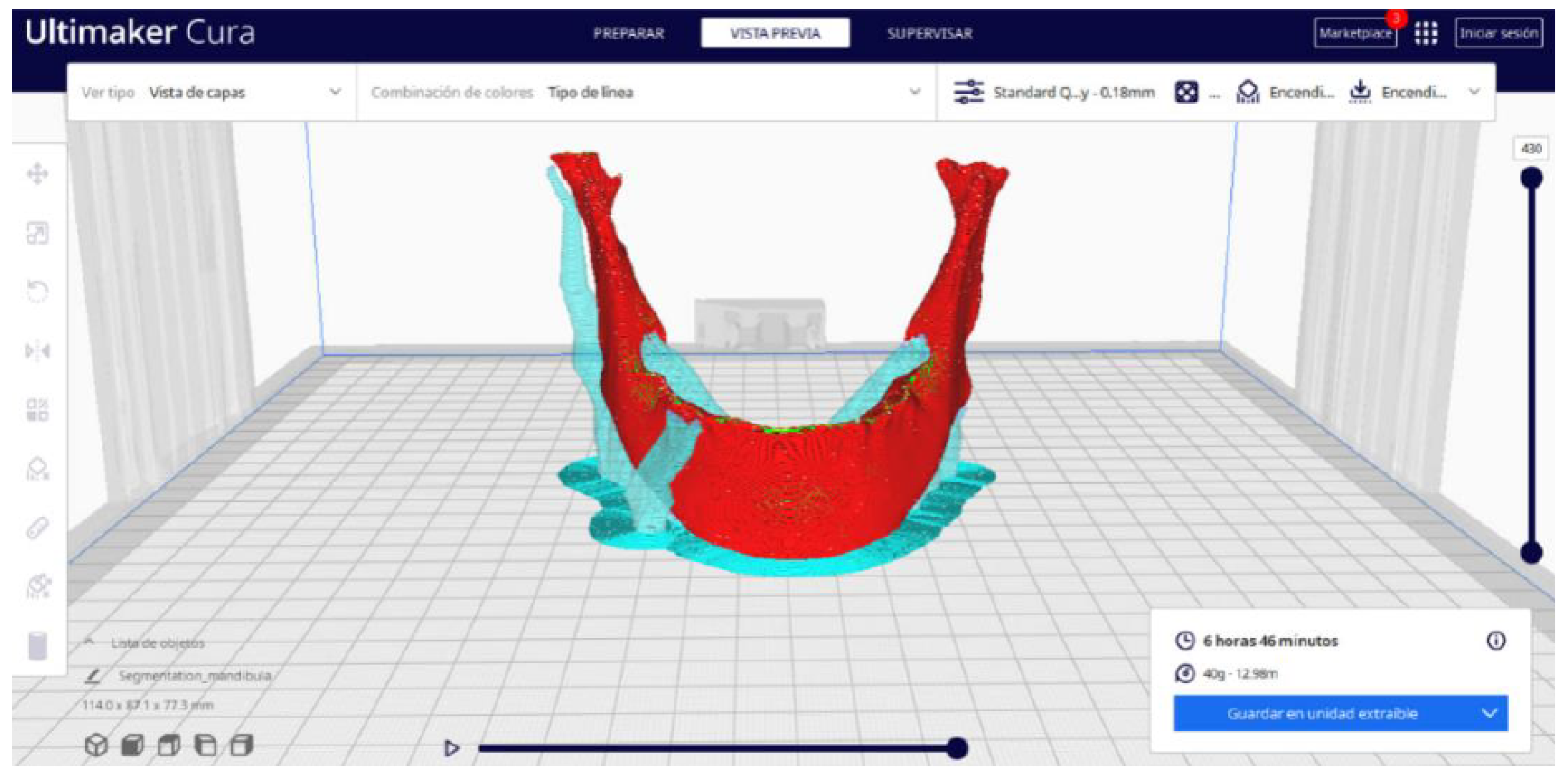
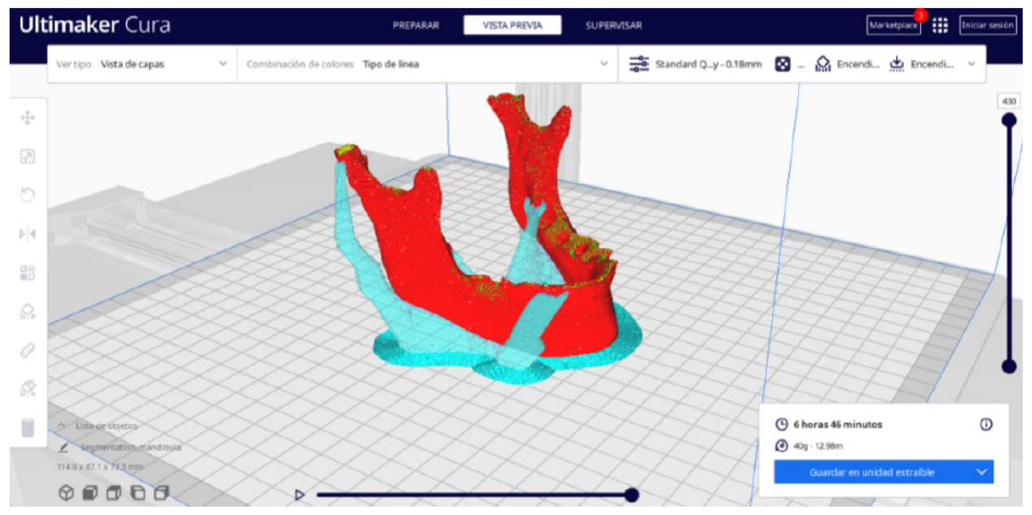
- Once the segmentation is complete, go to the “Preview” option. Here, a sidebar will appear on the right side of the screen, giving you the ability to preview the materialisation process layer by layer, from the base to the top of the model.
- Once all the print settings are configured, select the “File” option in the Ultimaker Cura menu.
- Choose the “Export” option, and select “GCODE” as the output file type.
- Save the GCODE file to the desired location for later use in your 3D printer.
3. Results and Discussion
- The DICOM-to-STL protocol, using 3D Slicer.
- The STL-to-GCODE protocol, using Ultimaker Cura.
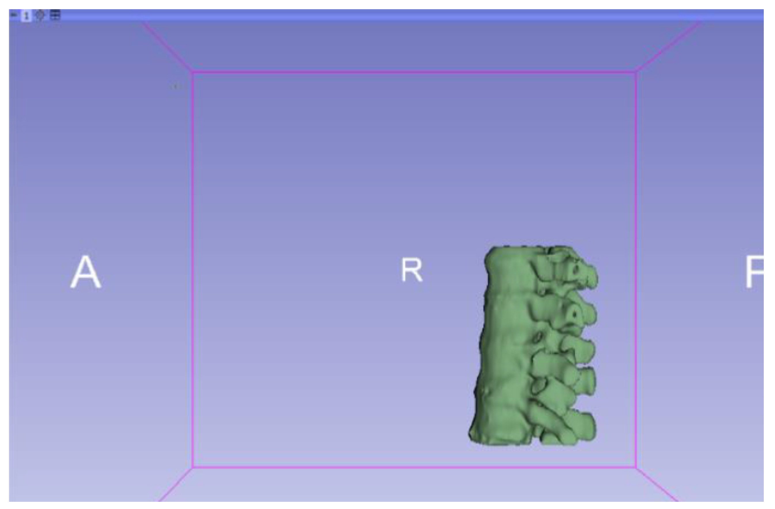
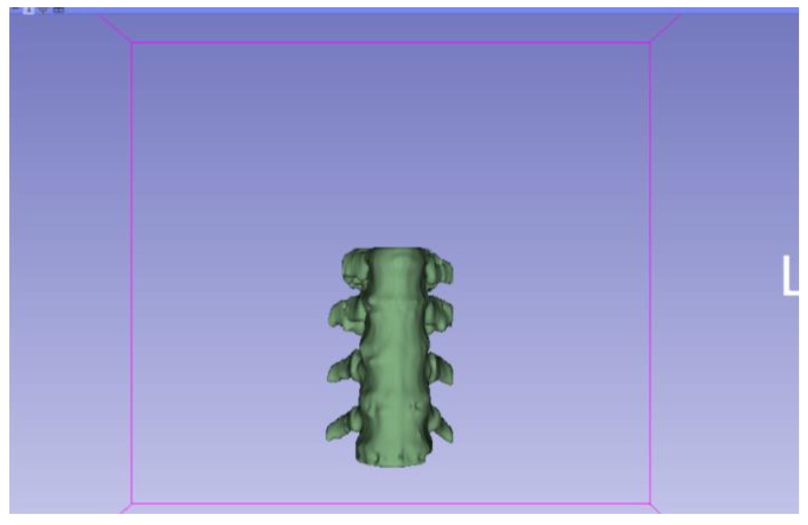
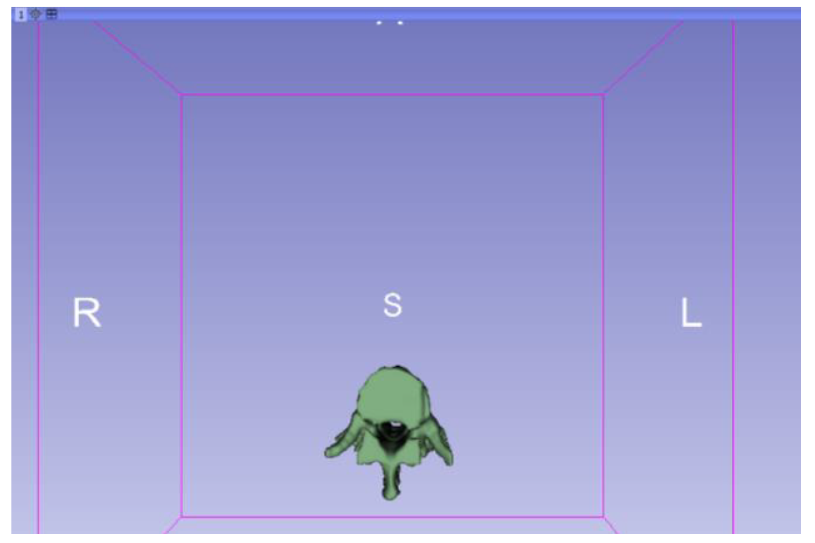
3.1. A Simple and Common Case
3.1.1. DICOM-to-STL File


3.1.2. STL-to-GCODE File
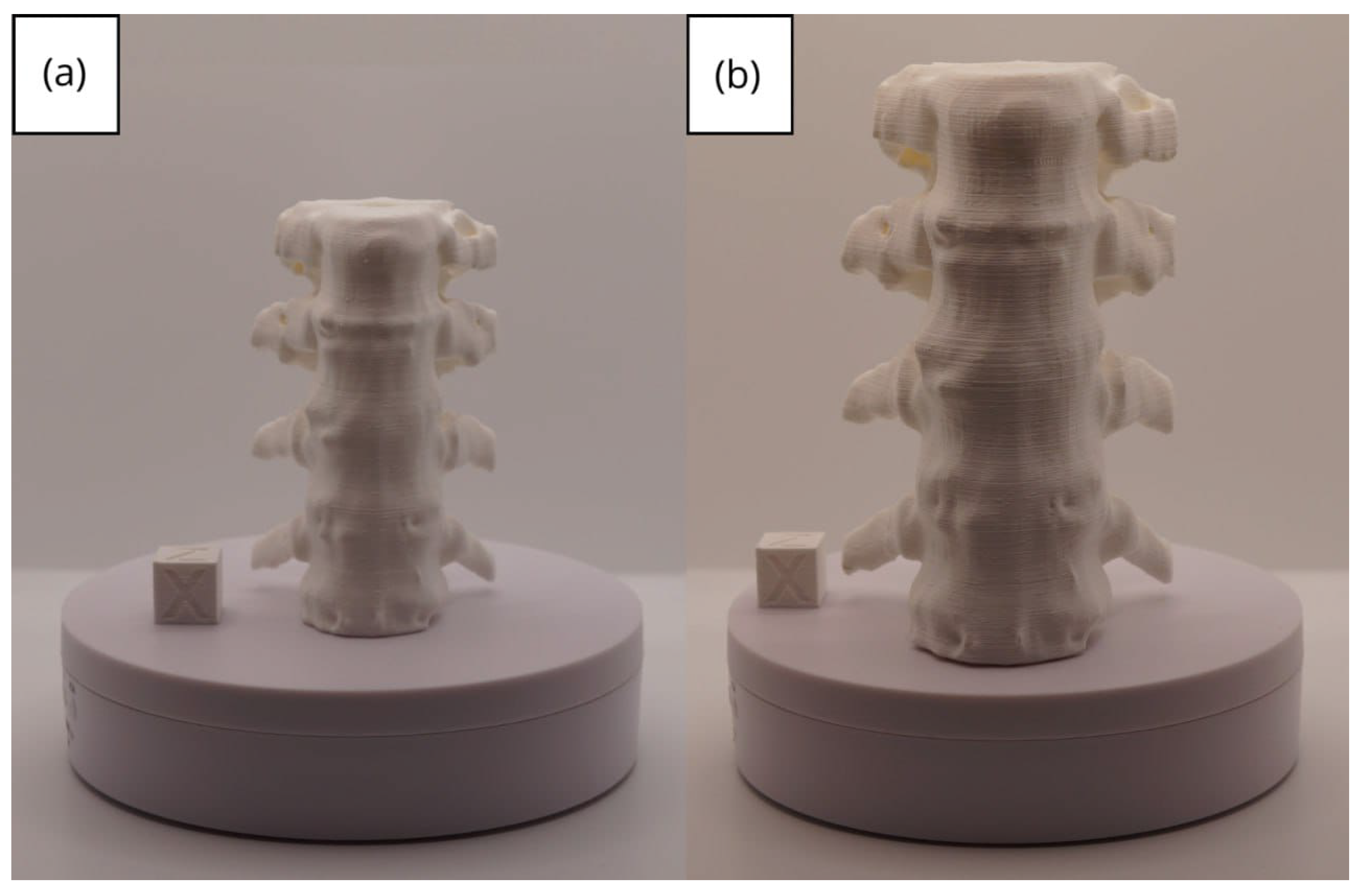
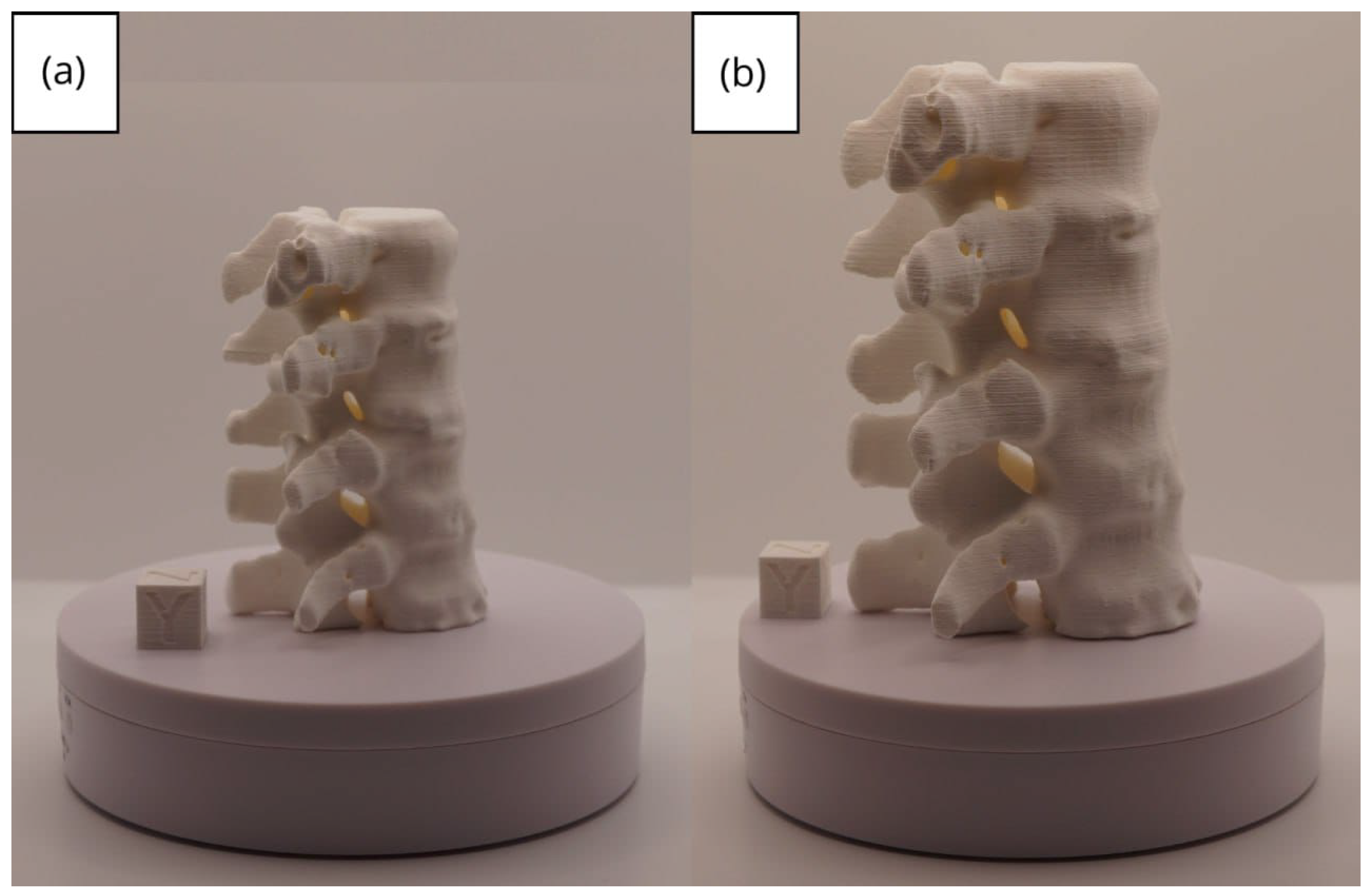
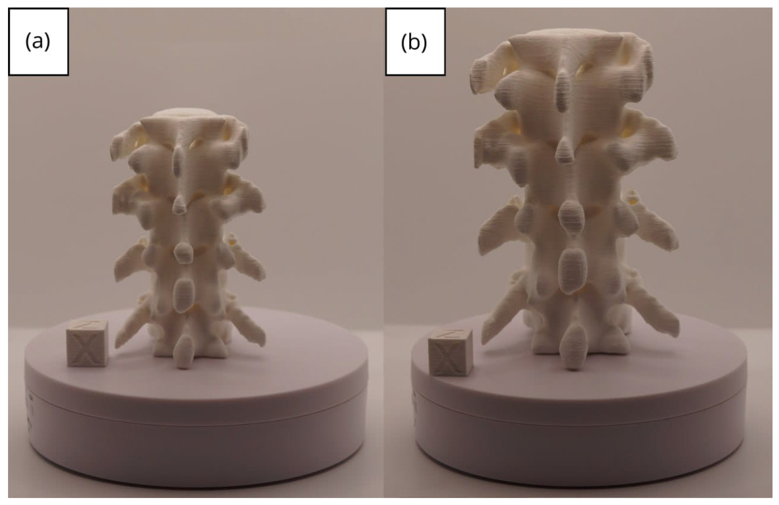
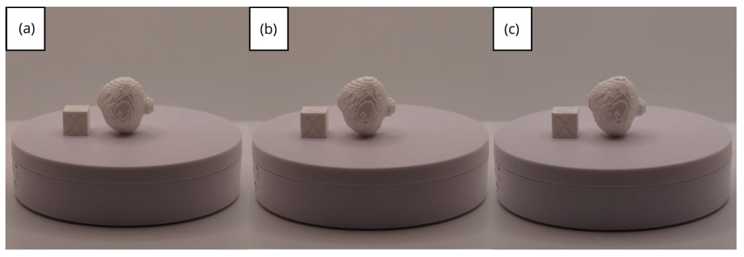
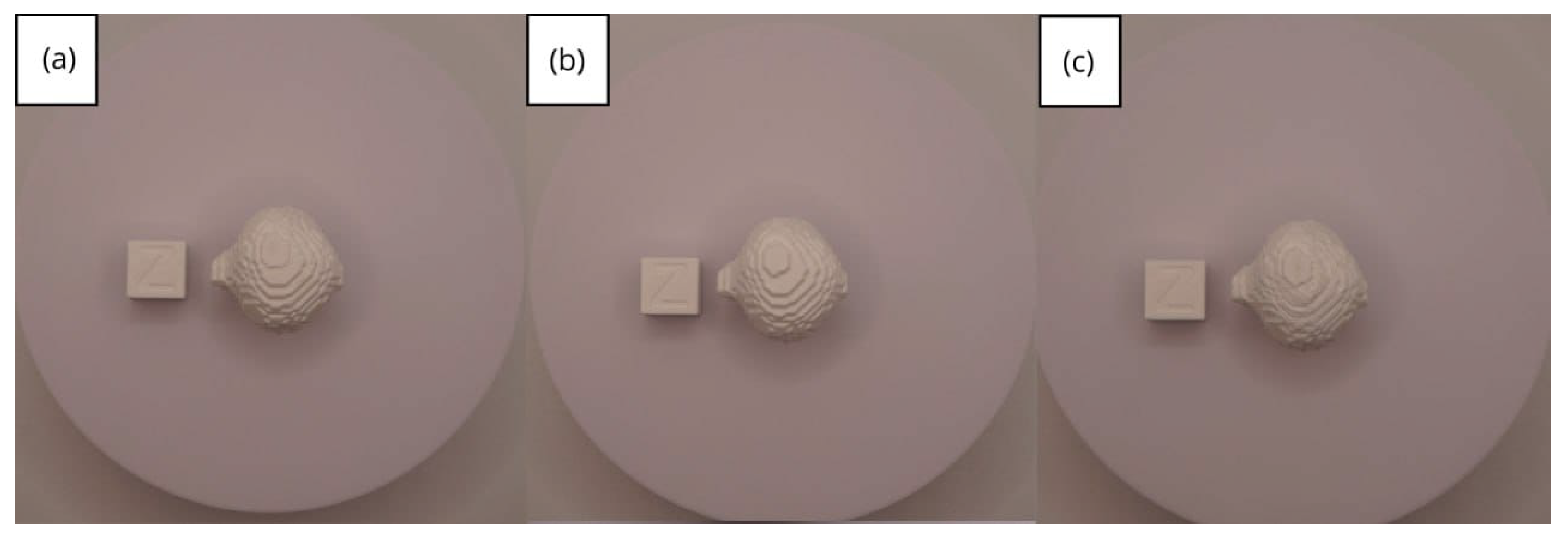
3.1.3. Final Printing
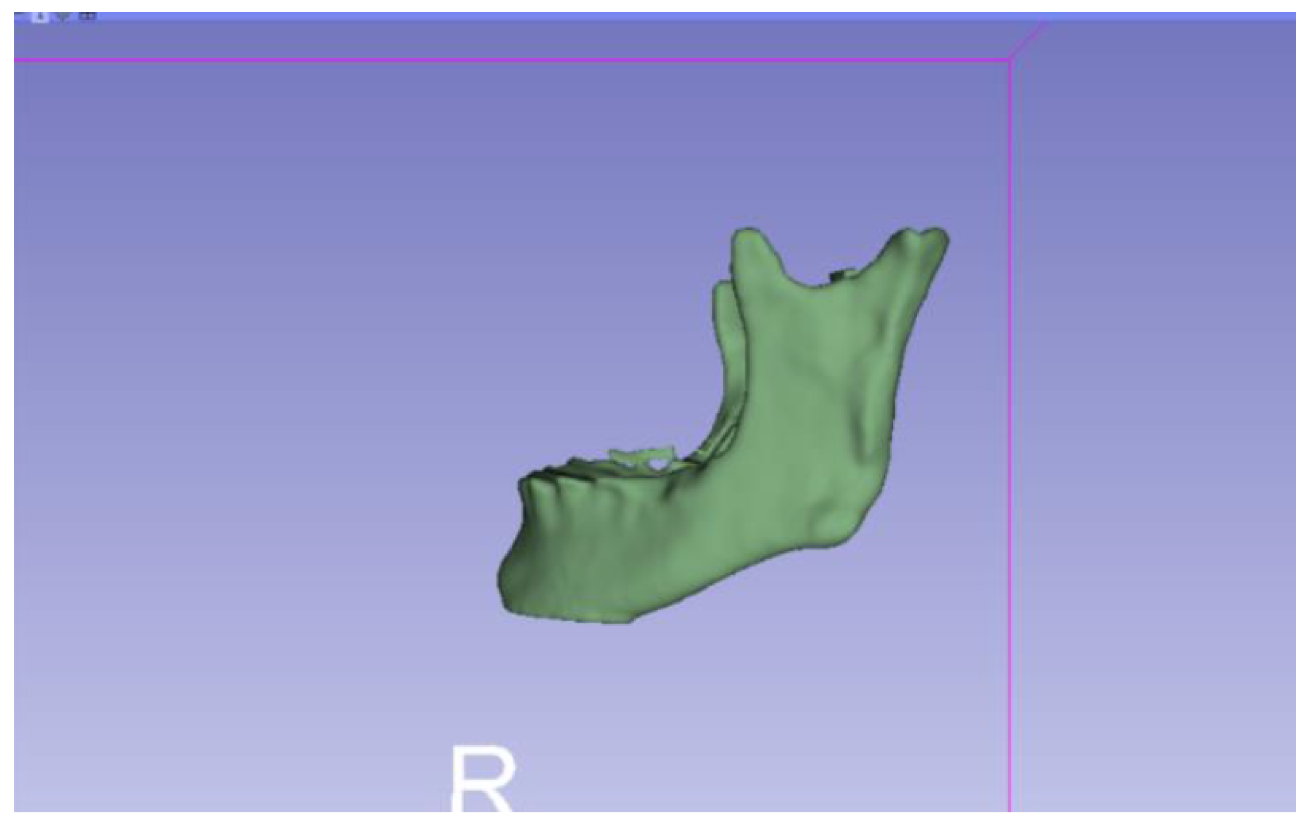
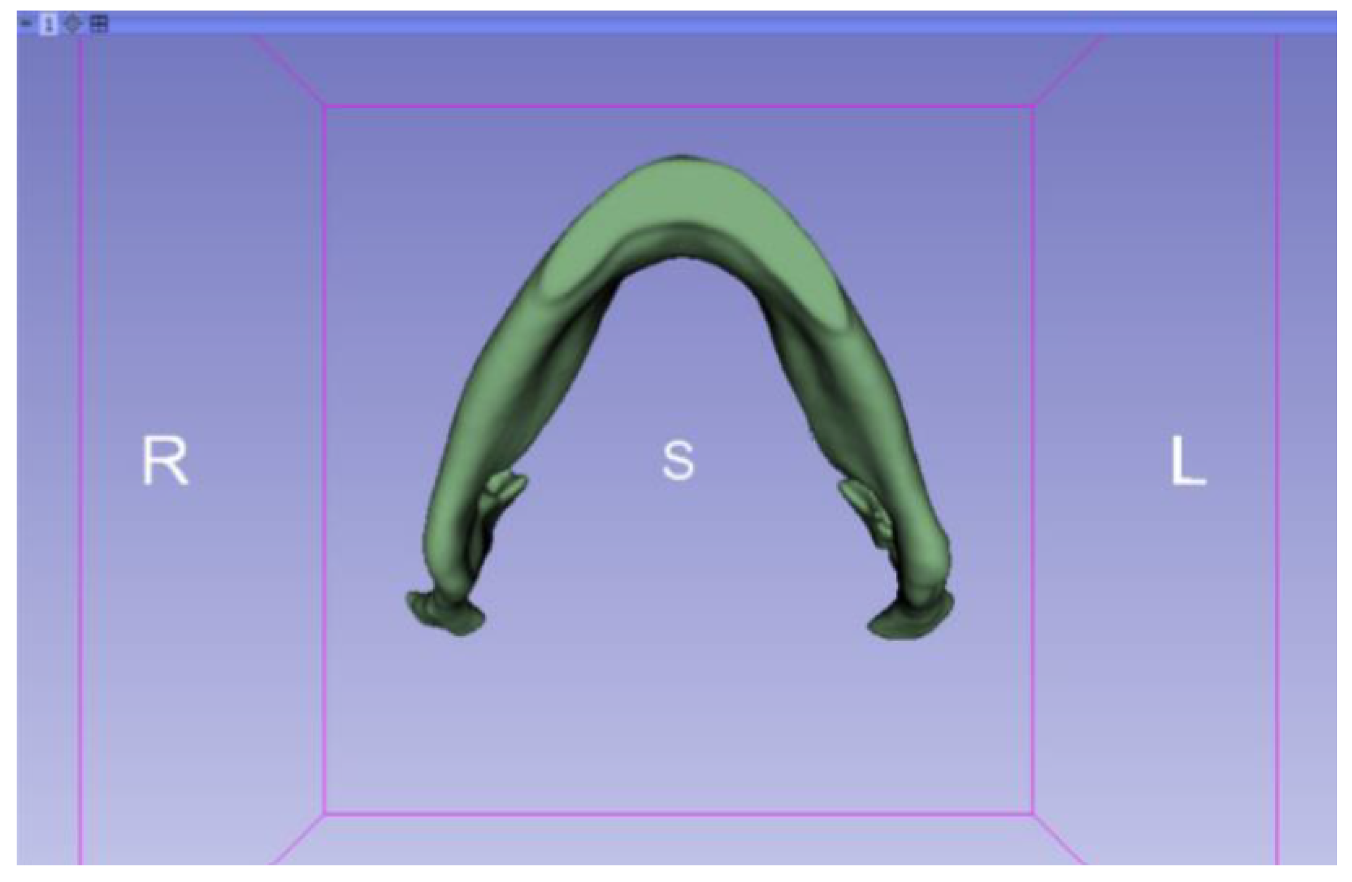
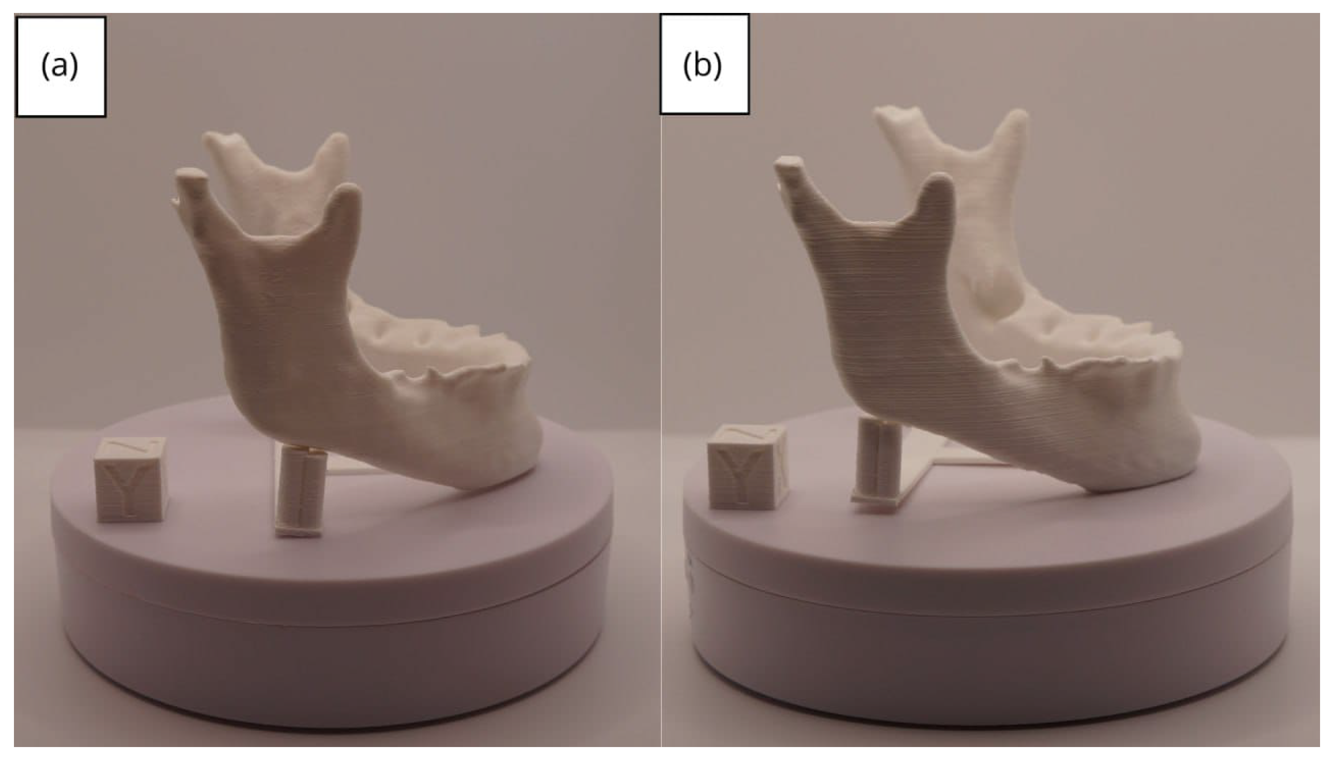
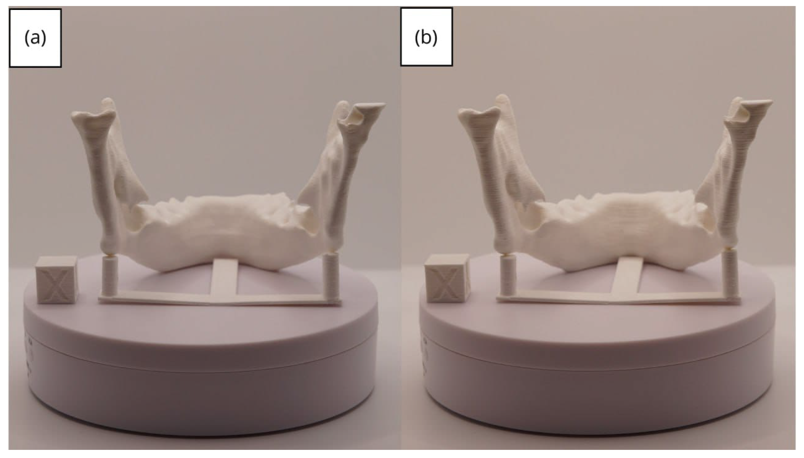
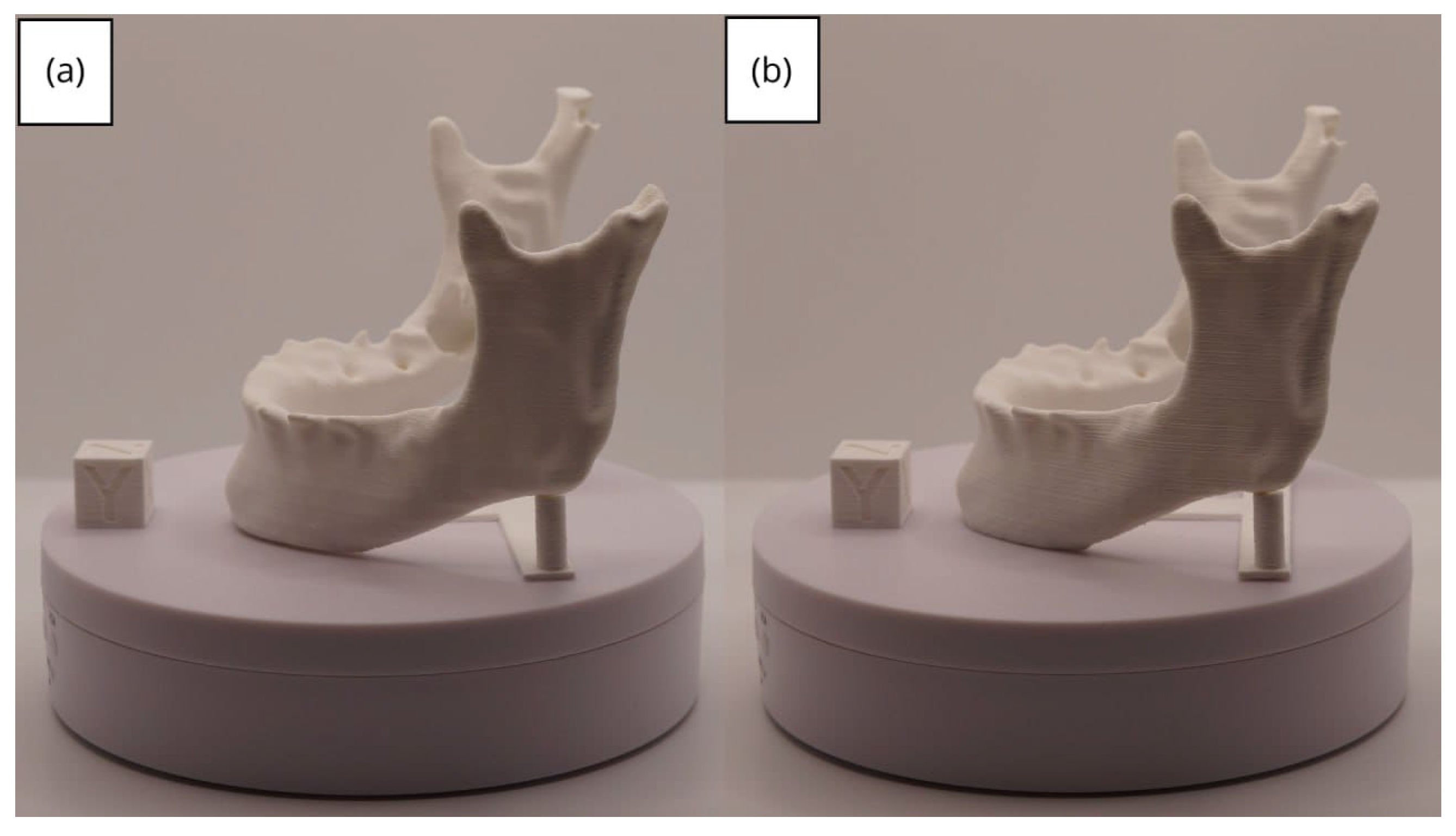
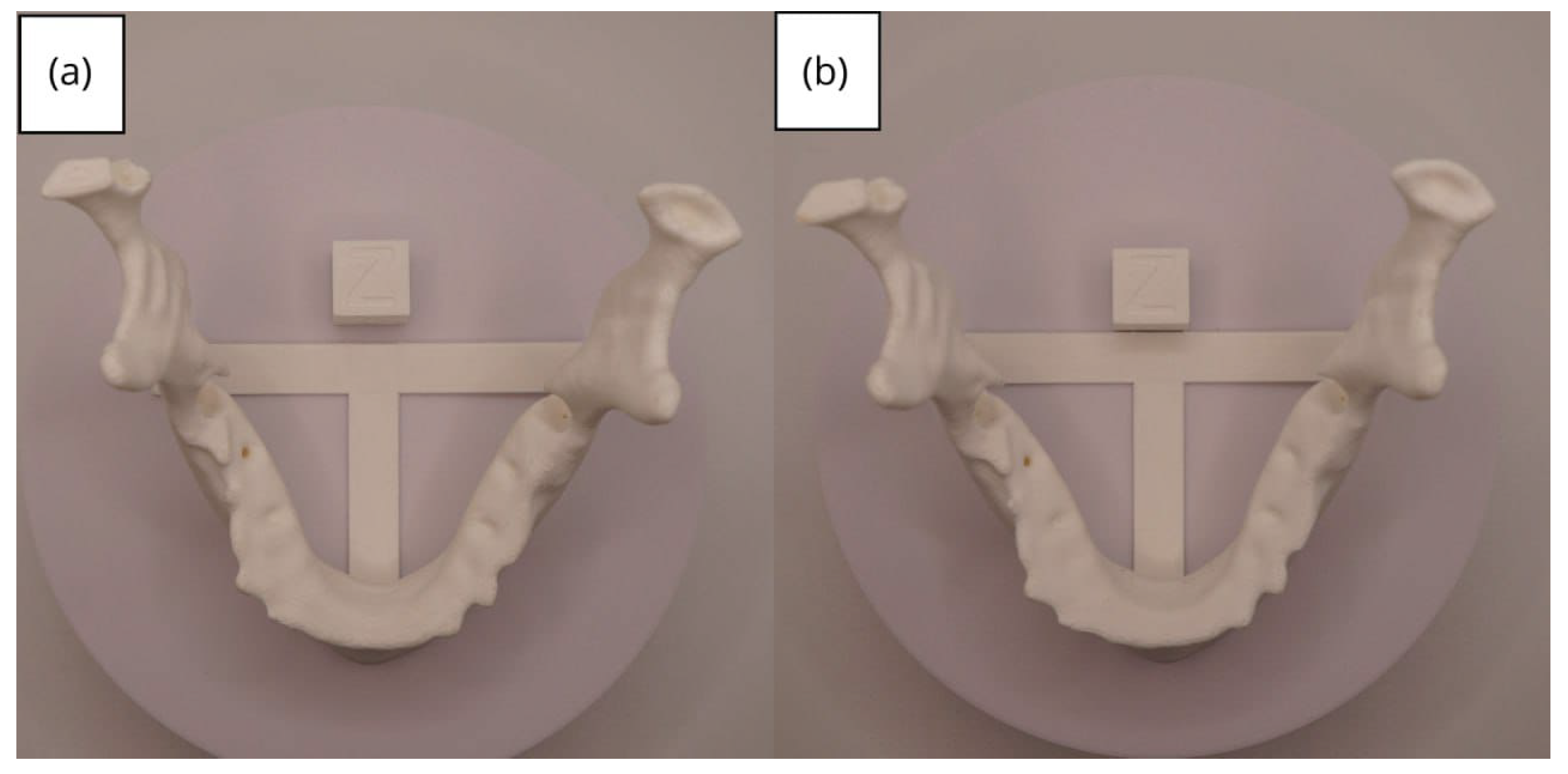
3.2. Human Lower Jaw
3.2.1. DICOM-to-STL Files
3.2.2. STL-to-GCODE Files
3.2.3. Final Printing
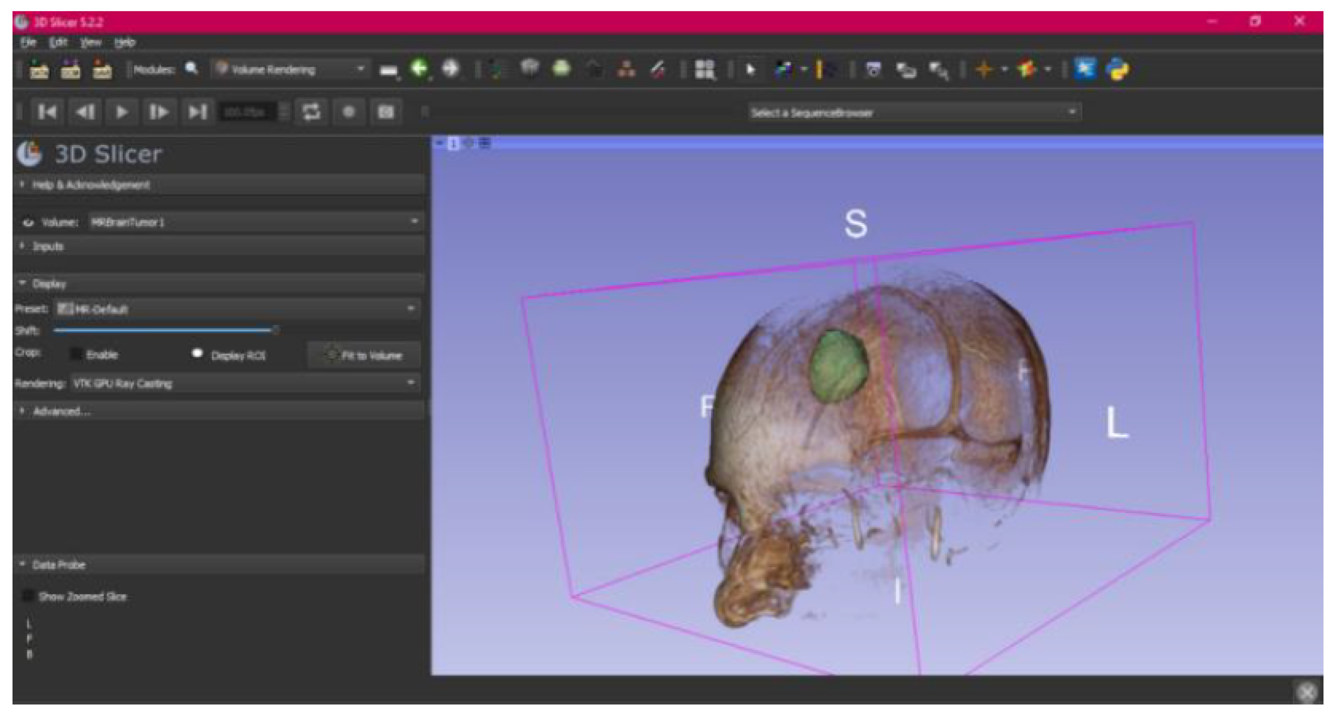
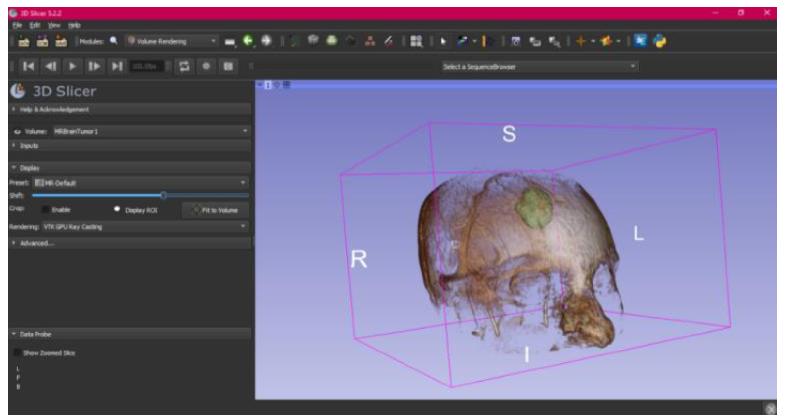
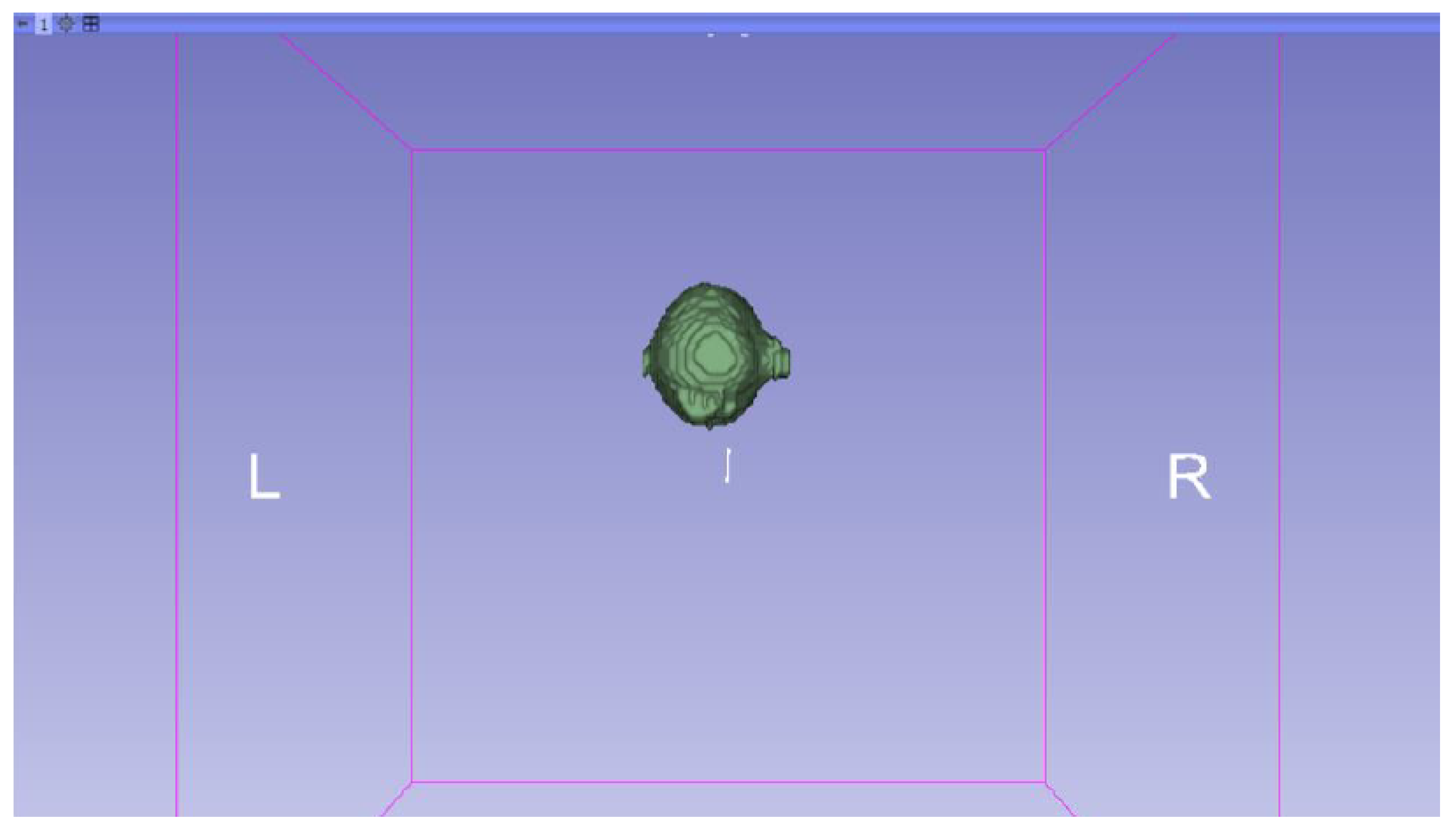
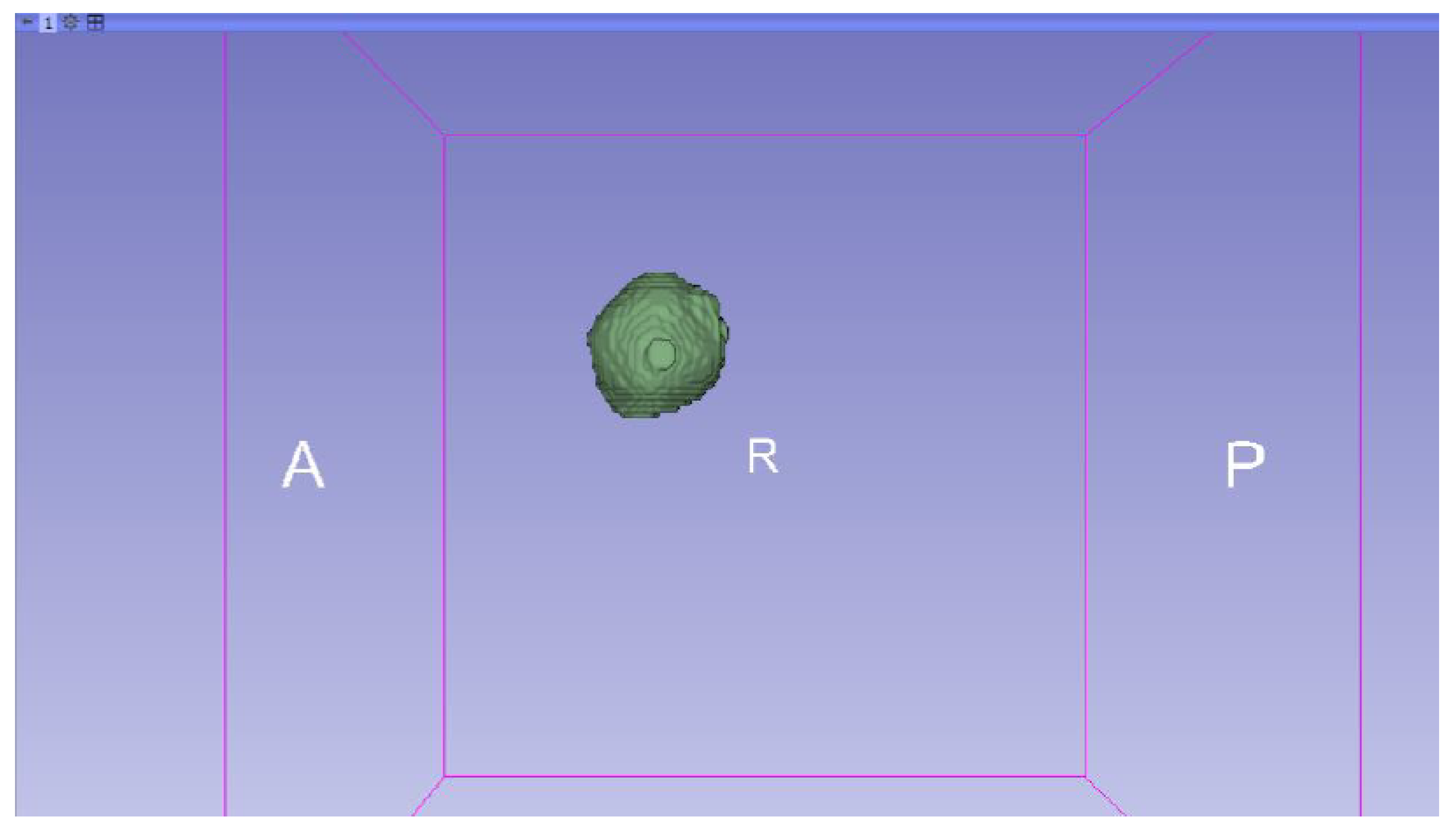
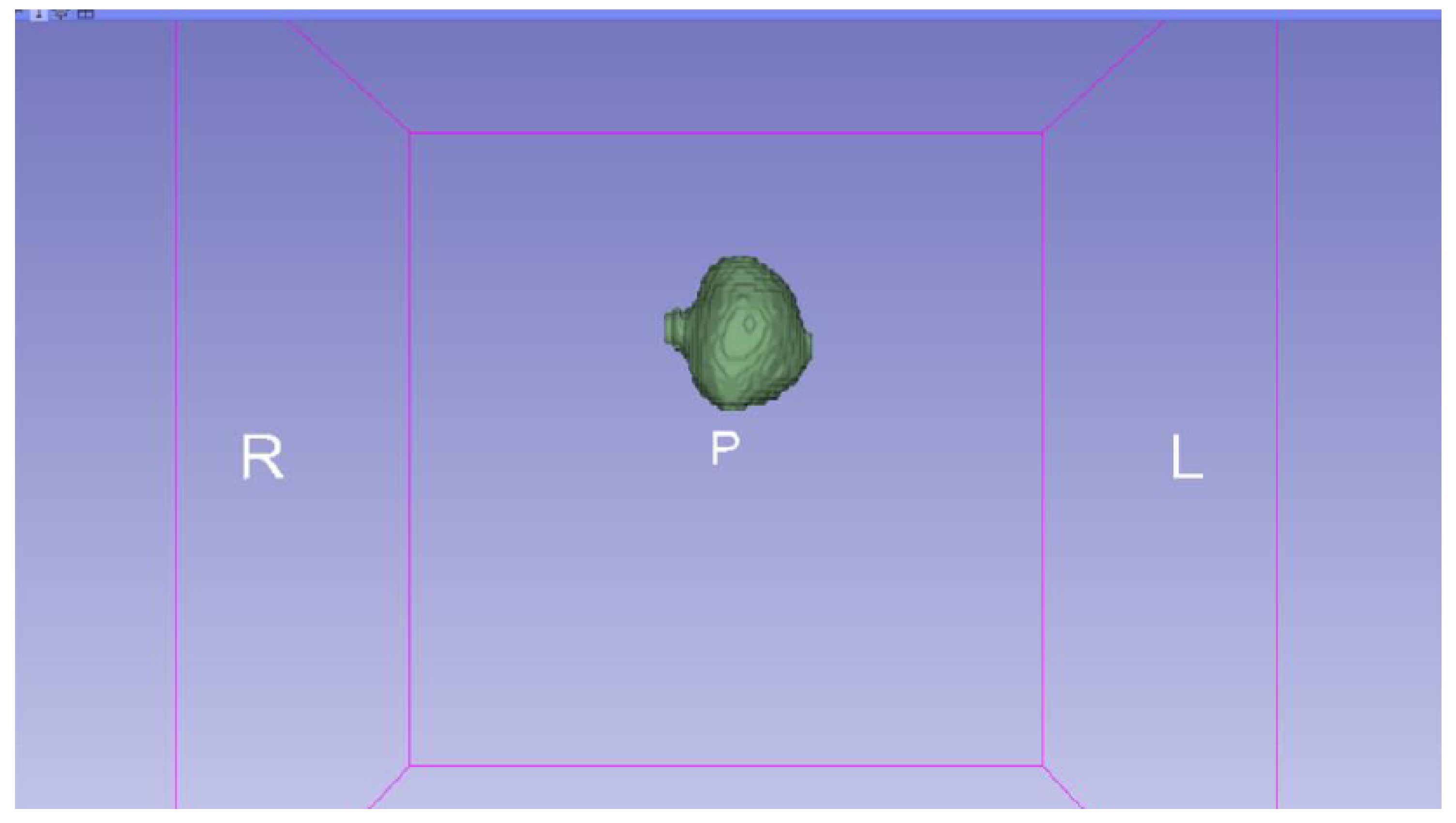
3.3. Human Brain Tumour
3.3.1. DICOM-to-STL Files
3.3.2. STL-to-GCODE Files
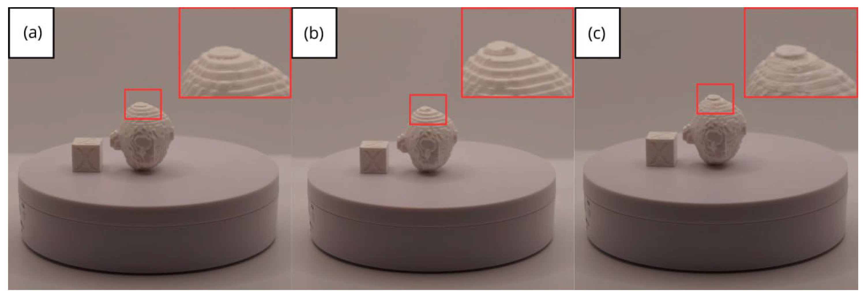
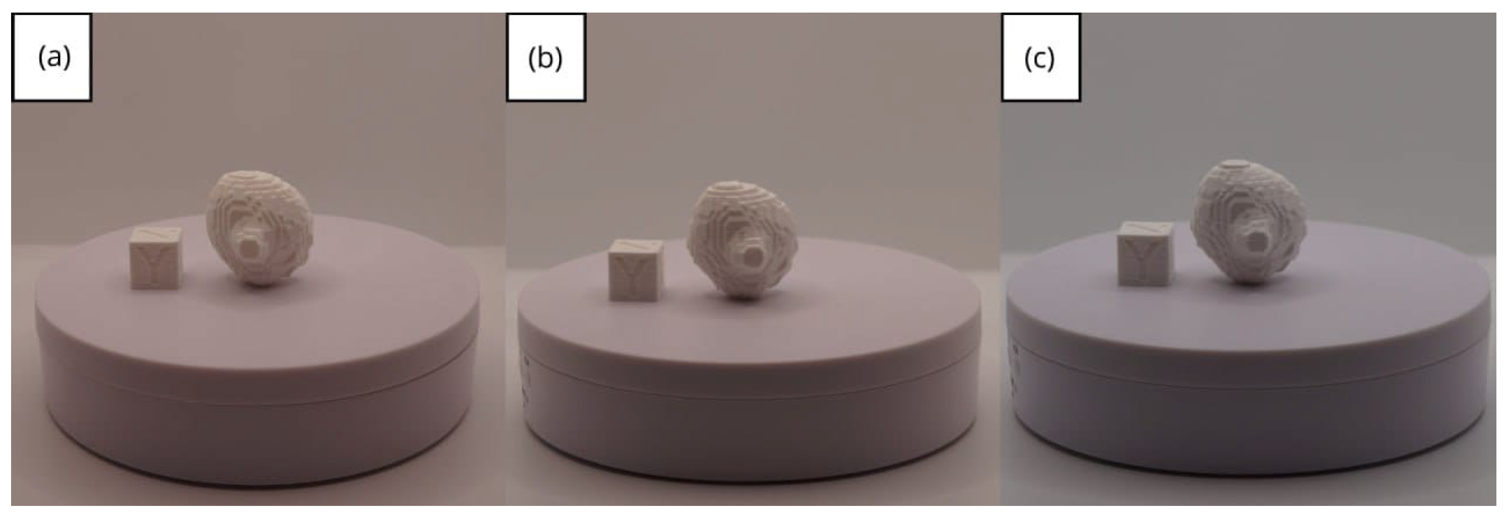
3.3.3. Final Printing
- Resolution loss: We can see in our protocol how the conversion process can lead to a reduction in image resolution, which could affect the fidelity of the 3D models. It is important to consider defining strategies in the DICOM file acquisition process to mitigate this resolution loss problem, such as optimising imaging parameters and carefully selecting segmentation thresholds. These losses are primarily dependent on the imaging process and are, therefore, beyond our control and the development of this protocol.
- Segmentation errors: The potential for inaccuracies to occur during the segmentation phase is acknowledged, with emphasis placed on the difficulties in distinguishing between tissues of similar densities. We emphasise the importance of operator experience and the use of advanced segmentation tools to minimise these errors.
- Software limitations: We examine the limitations associated with the open-source software used in our workflow, including processing capabilities and compatibility issues. Suggestions are provided to overcome these limitations, such as hardware upgrades and alternative software options.
4. Conclusions and Final Work
Supplementary Materials
Author Contributions
Funding
Institutional Review Board Statement
Informed Consent Statement
Data Availability Statement
Acknowledgments
Conflicts of Interest
References
- Boretti, A. A perspective on 3D printing in the medical field. Ann. 3D Print. Med. 2024, 13, 100138. [Google Scholar] [CrossRef]
- Ngo, T.D.; Kashani, A.; Imbalzano, G.; Nguyen, K.T.Q.; Hui, D. Additive manufacturing (3D printing): A review of materials, methods, applications and challenges. Compos. Part B Eng. 2018, 143, 176–196. [Google Scholar] [CrossRef]
- Ventola, C.L. Medical Applications for 3D Printing: Current and Projected Uses. Pharm. Ther. 2014, 39, 704–711. [Google Scholar]
- Kalaskar, D.M. (Ed.) 3D Printing in Medicine; Woodhead Publishing: Sawston, UK, 2022; Available online: https://books.google.es/books?id=qH9dEAAAQBAJ (accessed on 20 December 2024).
- Aguado-Maestro, I.; Simón-Pérez, C.; García-Alonso, M.; Ailagas-De Las Heras, J.J.; Paredes-Herrero, E. Clinical Applications of ’In-Hospital’ 3D Printing in Hip Surgery: A Systematic Narrative Review. J. Clin. Med. 2024, 13, 599. Available online: https://www.mdpi.com/2077-0383/13/2/599 (accessed on 20 December 2024). [CrossRef] [PubMed]
- Osti, F.; Santi, G.M.; Neri, M.; Liverani, A.; Frizziero, L.; Stilli, S.; Trisolino, G. CT conversion workflow for intraoperative usage of bony models: From DICOM data to 3D printed models. Appl. Sci. 2019, 9, 708. Available online: https://www.mdpi.com/2076-3417/9/4/708 (accessed on 20 December 2024). [CrossRef]
- Tam, M.D.; Laycock, S.D.; Brown, J.R.; Jakeways, M. 3D printing of an aortic aneurysm to facilitate decision making and device selection for endovascular aneurysm repair in complex neck anatomy. J. Endovasc. Ther. 2013, 20, 863–867. [Google Scholar] [CrossRef] [PubMed]
- Srinivasan, D.; Meignanamoorthy, M.; Ravichandran, M.; Mohanavel, V.; Alagarsamy, S.V.; Chanakyan, C.; Sakthivelu, S.; Karthick, A.; Prabhu, T.R.; Rajkumar, S. 3D printing manufacturing techniques, materials, and applications: An overview. Adv. Mater. Sci. Eng. 2021, 2021, 5756563. [Google Scholar] [CrossRef]
- Meyer-Szary, J.; Luis, M.S.; Mikulski, S.; Patel, A.; Schulz, F.; Tretiakow, D.; Fercho, J.; Jaguszewska, K.; Frankiewicz, M.; Pawłowska, E.; et al. The Role of 3D Printing in Planning Complex Medical Procedures and Training of Medical Professionals-Cross-Sectional Multispecialty Review. Int. J. Environ. Res. Public Health 2022, 19, 3331. [Google Scholar] [CrossRef] [PubMed]
- Paxton, N.C.; Wilkinson, B.G.; Fitzpatrick, D.; Owen, E.C.; Luposchainsky, S.; Dalton, P.D. Technical improvements in preparing 3D printed anatomical models for comminuted fracture preoperative planning. 3D Print. Med. 2023, 9, 25. [Google Scholar] [CrossRef] [PubMed]
- Kapoor, K. 3D visualization and printing: An ’Anatomical Engineering’ trend revealing underlying morphology via innovation and reconstruction towards future of veterinary anatomy. Anat. Sci. Int. 2024, 99, 159–182. [Google Scholar] [CrossRef] [PubMed]
- Zhang, Y.; Feng, H.; Zhao, Y.; Zhang, S. Exploring the Application of the Artificial-Intelligence-Integrated Platform 3D Slicer in Medical Imaging Education. Diagnostics 2024, 14, 146. [Google Scholar] [CrossRef] [PubMed]
- Grunert, R.; Winkler, D.; Frank, F.; Moebius, R.; Kropla, F.; Meixensberger, J.; Hepp, P.; Elze, M. 3D-printing of the elbow in complex posttraumatic elbow-stiffness for preoperative planning, surgery-simulation and postoperative control. 3D Print. Med. 2023, 9, 28. [Google Scholar] [CrossRef] [PubMed]
- Vaz, V.M.; Kumar, L. 3D printing as a promising tool in personalized medicine. AAPS Pharmscitech 2021, 22, 49. [Google Scholar] [CrossRef] [PubMed]
- STL (File Format). Wikipedia. 2024. Available online: https://en.wikipedia.org/wiki/STL_(file_format) (accessed on 20 December 2024).
- Editor. MT4SD. 2023. Available online: https://mt4sd.ulpgc.es/en/ (accessed on 20 December 2024).
- Segment Editor. 3D Slicer. 2023. Available online: https://slicer.readthedocs.io/en/latest/user_guide/modules/segmenteditor.html (accessed on 20 December 2024).
- Fused Deposition Modeling (FDM) 3D Printing Simply Explained. All3DP. 2024. Available online: https://all3dp.com/2/fused-filament-fabrication-fff-3d-printing-simply-explained/ (accessed on 20 December 2024).
- Artillery Sidewinder X2. Artillery 3D Printers. 2024. Available online: https://artillery3dprinters.es/artillery-x2/ (accessed on 20 December 2024).
- Creality Ender 3. Creality3D Official. 2024. Available online: https://www.creality3dofficial.com/es/products/official-creality-ender-3-3d-printer (accessed on 20 December 2024).
- Sample Data. 3D Slicer. 2024. Available online: https://slicer.readthedocs.io/en/latest/user_guide/modules/sampledata.html (accessed on 20 December 2024).
- Sukindar, N.A.; Md Yasir, A.S.H.; Azhar, M.D.; Md Azhar, M.A.; Abd Halim, N.F.H.; Sulaiman, M.H.; Ahmad Sabli, A.S.H.; Ariffin, M.K.A.M. Evaluation of the surface roughness and dimensional accuracy of low-cost 3D-printed parts made of PLA–aluminum. Heliyon 2024, 10, e25508. [Google Scholar] [CrossRef] [PubMed]
- Kothandaraman, L.; Balasubramanian, N. Optimization of the Printing Parameters to Improve the Surface Roughness in Fused Deposition Modeling. E3S Web Conf. 2023, 399, 03003. [Google Scholar] [CrossRef]
- Bozoğulları, H.N.; Temizci, T. Evaluation of the Color Stability, Stainability, and Surface Roughness of Permanent Composite-Based Milled and 3D Printed CAD/CAM Restorative Materials after Thermocycling. Appl. Sci. 2023, 13, 11895. [Google Scholar] [CrossRef]
- Singh, D. Cone-beam Computed Tomography: A New Era in Clinical Orthodontics. Int. J. Health Sci. 2021, 5, 411–427. [Google Scholar] [CrossRef]


| Case Study | ST (HU) | SK | VS (mm) | LH (mm) | ID (%) |
|---|---|---|---|---|---|
| Vertebrae | [150, 300] | Median | 0.8 | 0.18 | 25 |
| Jawbone | [100, 250] | Gaussian | 0.6 | 0.20 | 40 |
| Brain Tumour | [90, 220] | None | 0.8 | 0.20 | 25 |
| Model | Data (Ra/Rz) | Printer |
|---|---|---|
| Vertebrae models | m; m | Artillery Sidewinder X2 |
| m; m | Creality Ender 3 | |
| Lower jaw models | m; m | Artillery Sidewinder X2 |
| m; m | Creality Ender 3 | |
| Brain tumour models | m; m | Artillery Sidewinder X2 |
| m; m | Creality Ender 3 |
Disclaimer/Publisher’s Note: The statements, opinions and data contained in all publications are solely those of the individual author(s) and contributor(s) and not of MDPI and/or the editor(s). MDPI and/or the editor(s) disclaim responsibility for any injury to people or property resulting from any ideas, methods, instructions or products referred to in the content. |
© 2025 by the authors. Licensee MDPI, Basel, Switzerland. This article is an open access article distributed under the terms and conditions of the Creative Commons Attribution (CC BY) license (https://creativecommons.org/licenses/by/4.0/).
Share and Cite
Pérez-Sevilla, M.; Rivas-Navazo, F.; Latorre-Carmona, P.; Fernández-Zoppino, D. Protocol for Converting DICOM Files to STL Models Using 3D Slicer and Ultimaker Cura. J. Pers. Med. 2025, 15, 118. https://doi.org/10.3390/jpm15030118
Pérez-Sevilla M, Rivas-Navazo F, Latorre-Carmona P, Fernández-Zoppino D. Protocol for Converting DICOM Files to STL Models Using 3D Slicer and Ultimaker Cura. Journal of Personalized Medicine. 2025; 15(3):118. https://doi.org/10.3390/jpm15030118
Chicago/Turabian StylePérez-Sevilla, Malena, Fernando Rivas-Navazo, Pedro Latorre-Carmona, and Darío Fernández-Zoppino. 2025. "Protocol for Converting DICOM Files to STL Models Using 3D Slicer and Ultimaker Cura" Journal of Personalized Medicine 15, no. 3: 118. https://doi.org/10.3390/jpm15030118
APA StylePérez-Sevilla, M., Rivas-Navazo, F., Latorre-Carmona, P., & Fernández-Zoppino, D. (2025). Protocol for Converting DICOM Files to STL Models Using 3D Slicer and Ultimaker Cura. Journal of Personalized Medicine, 15(3), 118. https://doi.org/10.3390/jpm15030118