Abstract
The third-generation instrument era is approaching, and the Einstein Telescope (ET) giant interferometer is becoming a reality, with the potential to be installed at an underground site where seismic noise is about 100 times lower than at the surface. Moreover, new available technologies and the experience acquired from operating advanced detectors are key to further extending the detection bandwidth down to 2–3 Hz, with the possibility of suspending a cryogenic payload. The New Generation of Super-Attenuator (NGSA) is an R&D project aimed at the improvement of vibration isolation performance for thirrd-generation detectors of gravitational waves, assuming that the present mechanical system adopted for the advanced VIRGO interferometer (second generation) is compliant with a third-generation detector. In this paper, we report the preliminary results obtained from a simulation activity devoted to the characterization of a mechanical system based on a multi-stage pendulum and a double-inverted pendulum in a nested configuration (NIP). The final outcomes provide guidelines for the construction of a reduced-scale prototype to be assembled and tested in the “PLANET” laboratory at INFN Naples, where the multi-stage pendulum—equipped with a new magnetic anti-spring (nMAS)—will be hung from the NIP structure.
1. Introduction
Seismic noise and local disturbances are dominant noise sources for ground-based gravitational wave detectors in the low-frequency region (0.1–10 Hz), limiting their sensitivity and duty cycle [1]. With the introduction of high-performance seismic isolation systems based on a multi-stage mechanical pendulum, the second generation laser interferometric detectors have reached the scientific goal of the first direct observation of GW signals. This was made possible thanks to the extension of the detection bandwidth down to 10 Hz. For third-generation instruments, like ET [2], the goal is the improvement of the current sensitivity by about a factor of 10, extending the observation bandwidth down to about 2–3 Hz [3]. These requirements demand important improvements with respect to the present experimental limits (more than five orders of magnitude) while also defining important guidelines for technologies to be implemented in different fields (Figure 1).
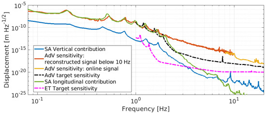
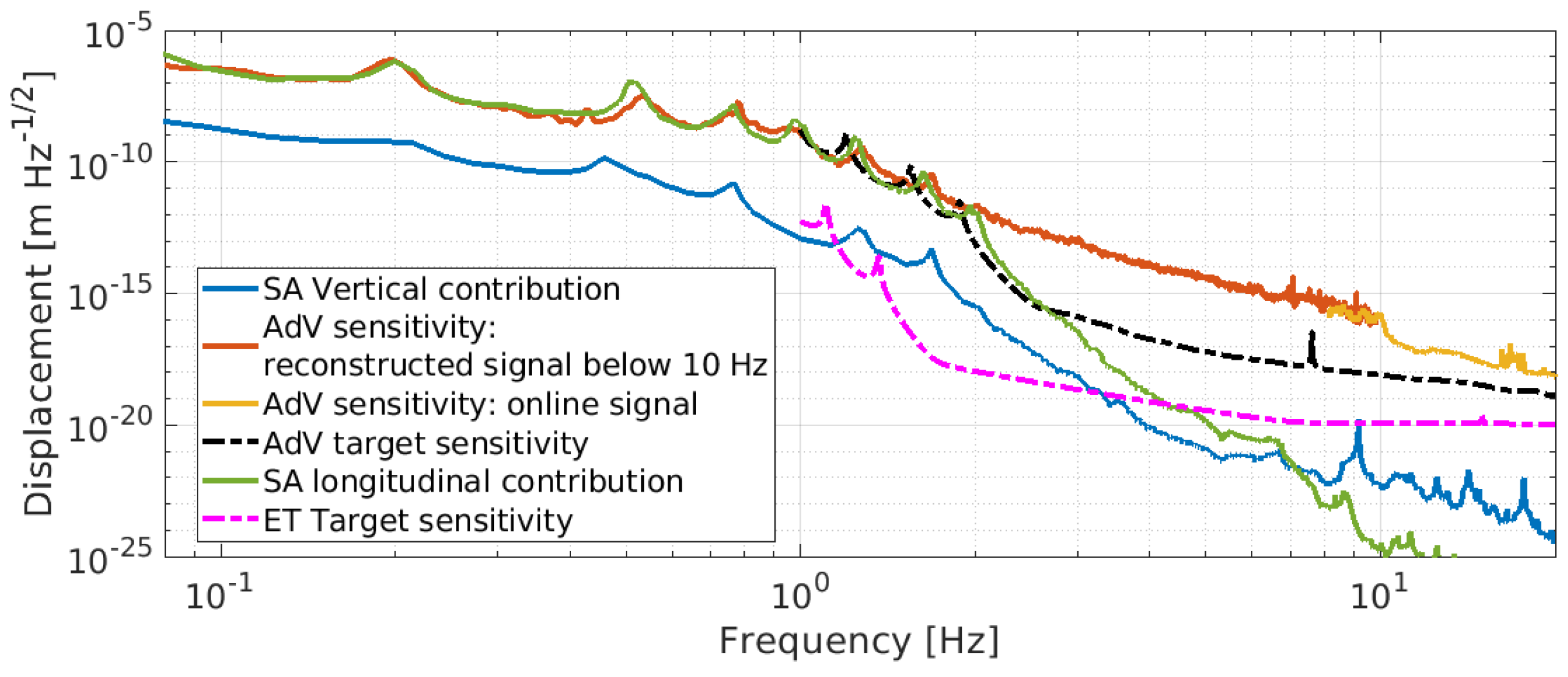
Figure 1.
Displacement sensitivity of second-generation detector AdV compared with its design sensitivity and the ET target sensitivity.
A modern gravitational wave instrument requires a complex mechanical system to isolate and suppress seismic noise from ground to the test masses. So far, the seismic isolation systems used in current GW detectors are based on the idea of suspending a chain of harmonic oscillators in a cascade to filter out the transmitted noise at the test mass level across all degrees of freedom. In this way, a chain of second-order low-pass mechanical filters is obtained, and the test mass can be considered a free-falling body starting from a few Hz. To meet detector requirements, over the last twenty years, great efforts have been made to develop these kinds of system. In [1,4,5,6,7,8,9,10,11], more details are given about the current seismic isolation system used in LIGO and KAGRA detectors. Information and a detailed description of the advanced VIRGO super-attenuator (SA) can be found in [12,13,14]. The SA is a passive and active system included in the interferometer layout to filter seismic noise and suspend optical components. It represents a cornerstone of current technology as well as a reference solution for the future seismic isolation system of the ET.
Indeed, the mechanical configuration of the SA represents the starting point for the NGSA R&D project, which started at the beginning of 2022 and has been approved and funded by INFN commission 5 (CSN5). A primary objective of the NGSA is to revisit the mechanical configuration of the SA with a view to enhancing its filtering performance, thereby ensuring compliance with the target sensitivity of the ET from 2–3 Hz. This will be achieved by considering two different solutions. The first solution consists of a longer (12 m) version of the SA equipped with a three-leg inverted pendulum pre-isolation stage supporting a multi-stage pendulum and a payload. As an alternative solution, a two-stage nested inverted pendulum (NIP) supporting a mechanical filter chain and payload is considered to complete the preliminary studies reported in [15].
Whilst there are encouraging preliminary results concerning the NIP-SA solution, there is currently no experimental confirmation of its feasibility or experimental verification of the actual performance of the NIP pre-isolator. Indeed, one of the main objectives of the NGSA R&D project is to build a 1:2 scale prototype of an NIP to experimentally validate its feasibility, performance, and criticality. The following section of this paper will focus on the frequency and performance study of a prototype NIP pre-isolator with a dummy mass of approximately 600 kg. In Section 2, the NIP geometry is described and its mechanical response is presented. In Section 3, the environmental noise and the characteristic noise of the sensors, actuators, and electronic boards involved in the control scheme of the prototype will be presented. Finally, the noise budget and the expected performance of the system will be discussed.
2. The NIP Prototype
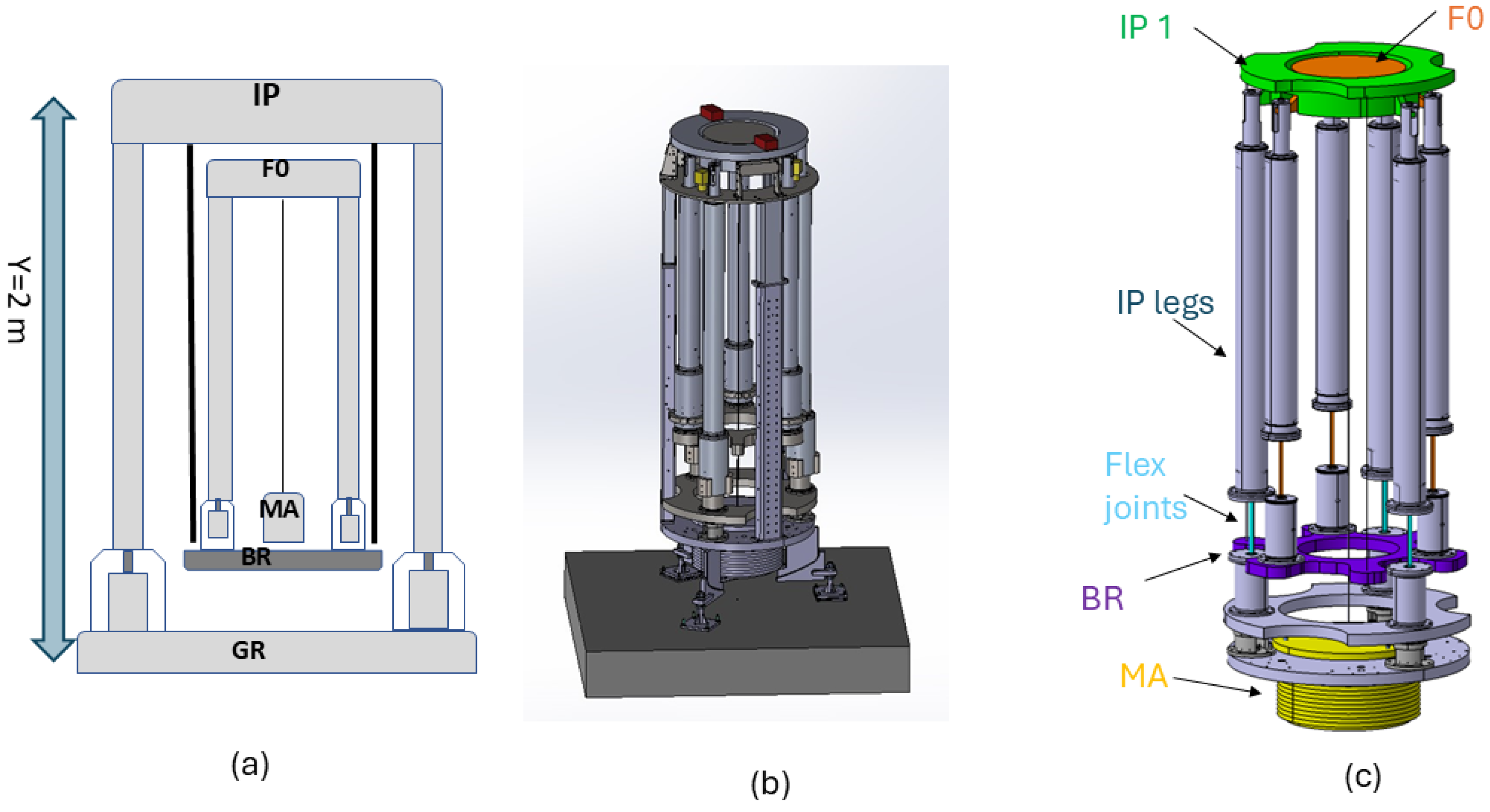
From a theoretical and conceptual standpoint, as indicated by the preliminary studies outlined in [15], an NIP-SA offers substantial advantages in terms of horizontal pre-isolator performance. However, there is currently no experimental evidence supporting its feasibility, as the NIP pre-isolator has not been fully realized, leaving several open questions, such as its actual mechanical stability, real mechanical coupling, and, importantly, its controllability. While simulations provide valuable insights, the construction of a prototype NIP pre-isolator is essential to answer these questions through empirical testing. As is customary in research and development, theoretical studies based on simulations are necessary to guide the dimensioning of mechanical parameters to achieve the desired performance before proceeding to the mechanical design and construction phase. The preliminary results of simulations on the frequency response of an NIP prototype (scale 1:2) will be presented below. Figure 2 shows the NIP prototype, a 2 m-tall mechanical structure. The system consists of a first inverted pendulum (IP) ground connected through its feet, on top of which a mechanical platform (BR) is hung. A second pre-attenuation stage (F0) is bolted to this last element, supporting a dummy mass (MA) of about 600 kg. The total load of the system is about 1200 kg. The length, dimensions, and mass of each element are set to have the first two modes of the NIP below 0.1 Hz. The prototype will be operated under high-vacuum conditions in order to avoid noise due to airflow.

Figure 2.
Two-dimensional sketch (a) and technical drawing of the NIP prototype (b,c). All the isolation stages are shown from top to bottom: the first pre-isolator (inverted pendulum (IP) ground connected through its feet) from which a mechanical platform (BR) is hung, supporting a second pre-attenuation stage (F0). A dummy mass (MA) is suspended from the top of the F0.
Modeling an NIP Prototype
In this subsection, we present the simulation methodology used to model and study the NIP prototype, going through the key transfer functions used as parameters to evaluate the system’s behavior. The final goal of this study is a detailed analysis of the system through its normal modes and cross-couplings, as well as verifying the stability and performance of the structure even when the control loops are engaged.
The mechanical response of the system has been studied using a custom-made simulation tool named OCTOPUS [16] (based on Matlab commercial code) in combination with the mass optimization method described in [17]. Without going into further detail, within the OCTOPUS environment, the properties of each mechanical element of the chain are represented either by a rigid body (mass) or by an elastic element (wires, joints). All this information is kept in a matrix , which is referred to as the impedance matrix. Each rigid body constitutes a node of the chain, to which one elastic element (link) is associated. In this way, a complex mechanical system is described as a collection of different nodes and links that are connected in a series or in parallel. The transfer function of the model is obtained using the impedance matrix algebra. According to these rules, the impedance matrix of the overall NIP is calculated by combining the impedance matrices of the individual mechanical elements and elastic links. Upon passing through the description of the system illustrated in Figure 2 (from the suspended mass to the IP), the following matrices must be calculated: the impedance relating to the dummy mass (MA), ; the impedance relating to the wire suspending the mass to the inverted pendulum F0, ; the matrix of the stage F0 consisting of a three-leg inverted pendulum and an F0 mass, ; the matrix relating to the platform on which the F0 stage sits, ; the matrix relating to the wires suspending the BR, ; and finally, the matrix relating to the IP stage, . Due to space limitations, the complete mathematical expressions of these matrices are not presented in this paper. However, a comprehensive analytical expression can be found in [16].
The is finally obtained by connecting the matrices listed above in a series as follows:
The impedance matrix obtained with Equation (1) represents the overall system under study and it is used to calculate the transfer functions. The result of this computation provides a 12 × 12 complex matrix whose elements are the transfer functions for a selected degree of freedom (d.o.f.) of the system.
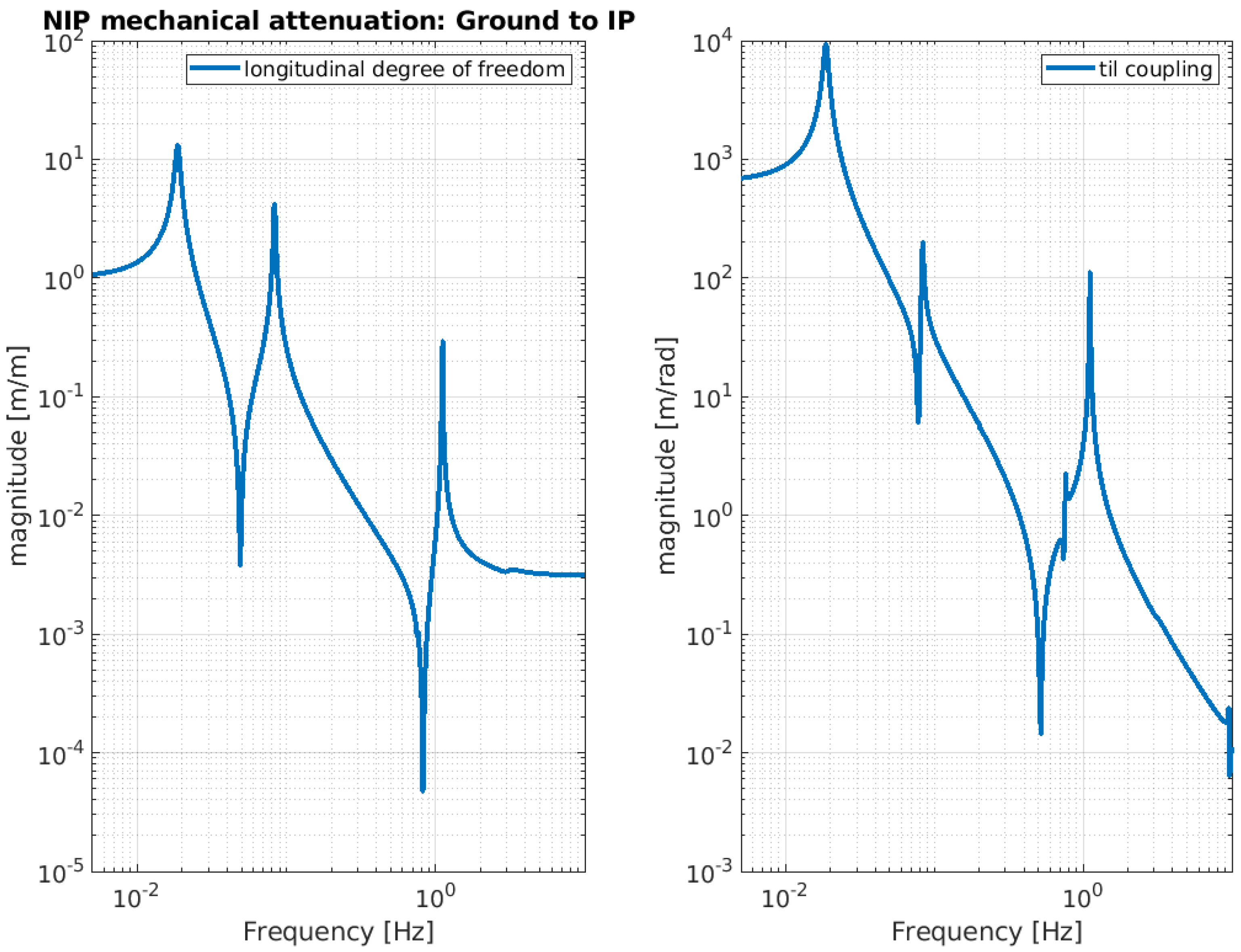
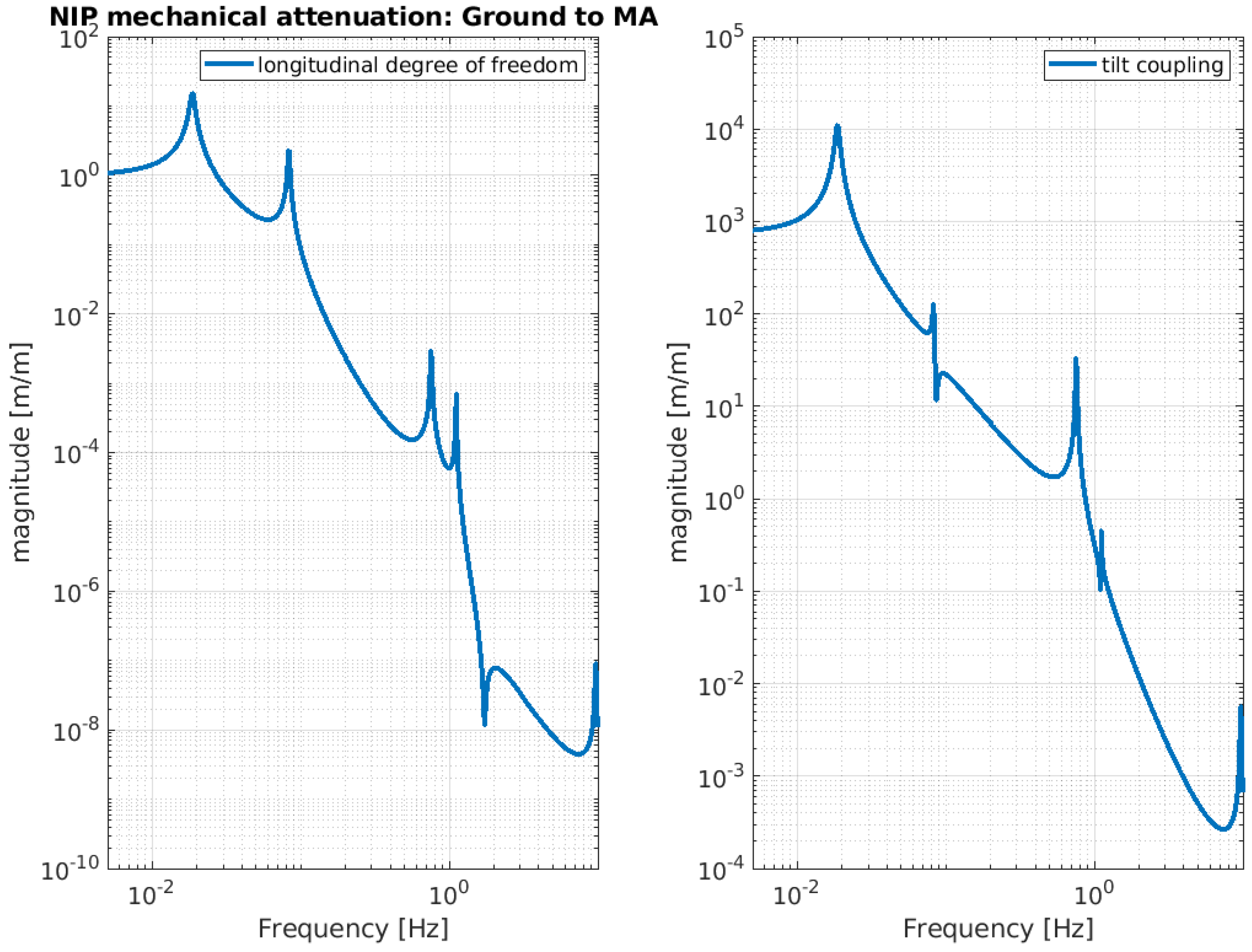
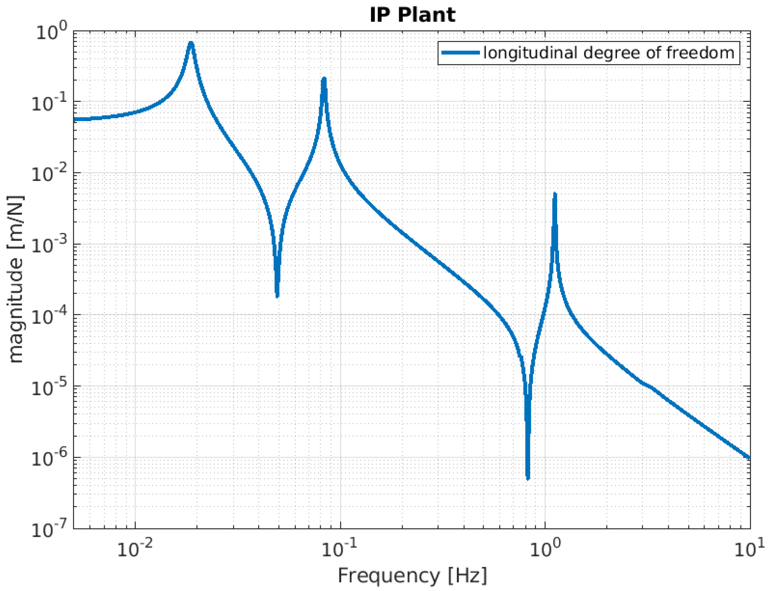
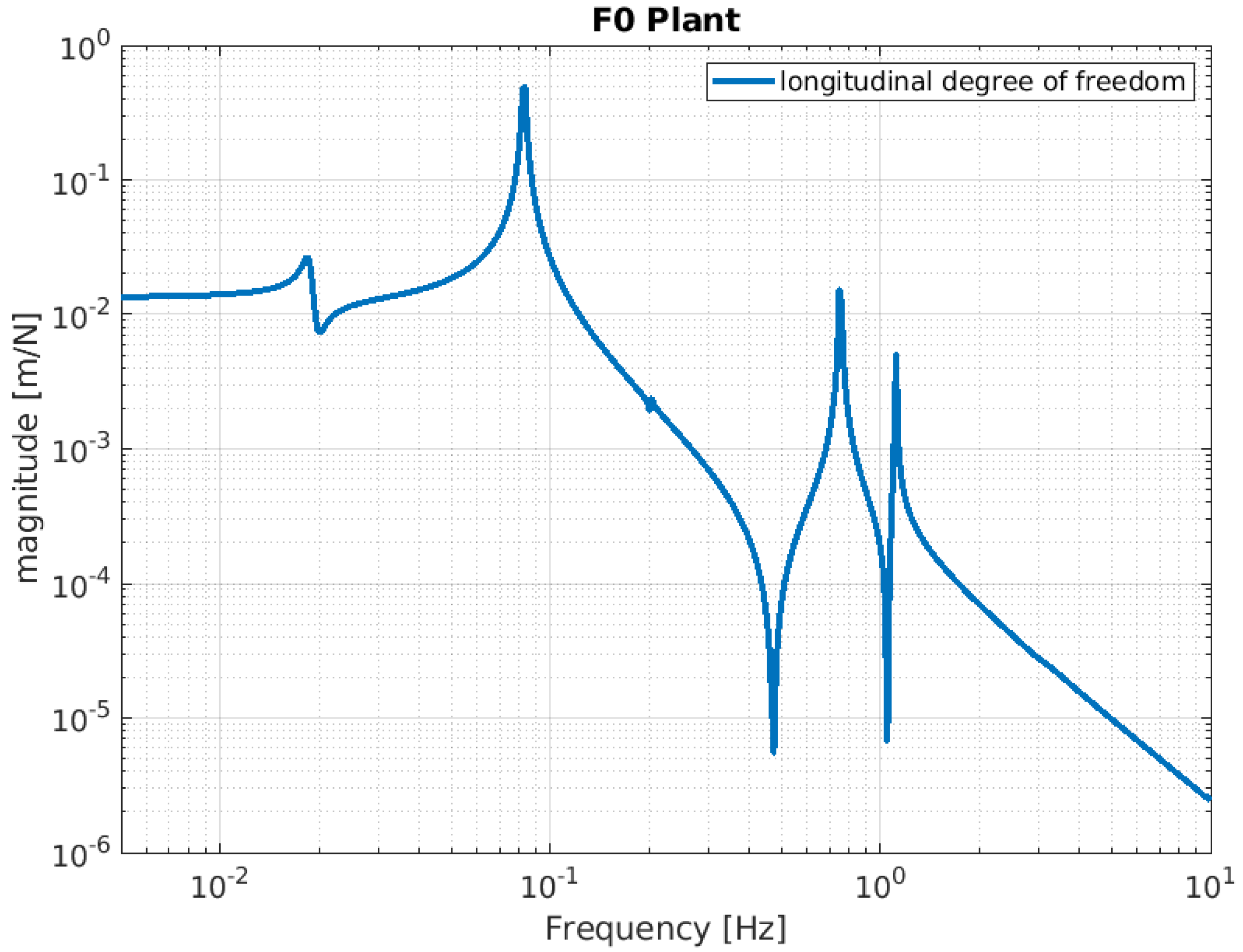
Below, the evaluation performance of the NIP prototype is plotted through a set of transfer functions. In particular, Figure 3, Figure 4 and Figure 5 show the outcome of the simulated response for the longitudinal d.o.f. and tilt-coupling degree of freedom; these are considered to evaluate the noise transmission the ground to IP, from ground to F0, and from ground to MA, respectively. The expected attenuation values of these transfer functions at 2 Hz are summarized in Table 1 for different stages of interest. For completeness, Figure 6 and Figure 7 depict the mechanical plants of the NIP prototype, respectively, when the actuation force is applied on the IP and F0 stages.

Figure 3.
NIP simulated transfer function. The function is calculated assuming the ground displacement as input and IP stage displacement as output. The left-hand image shows the longitudinal component and the right-hand image shows the tilt coupling component.
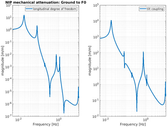
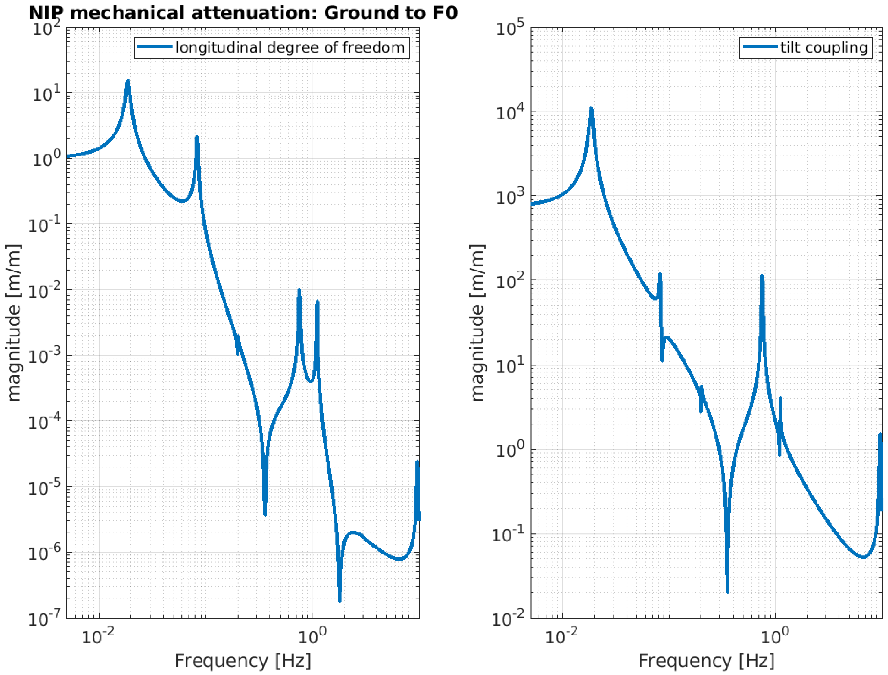
Figure 4.
NIP simulated transfer function. The function is calculated assuming the ground displacement as input and F0 stage displacement as output. The left-hand image shows the longitudinal component and the right-hand image shows the tilt coupling component.
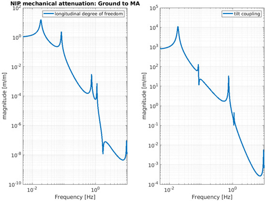
Figure 5.
NIP simulated transfer function. The function is calculated assuming the ground displacement as input and MA stage displacement as output. The left-hand image shows the longitudinal component and the right-hand image shows the tilt-coupling component.

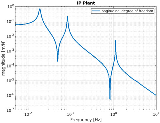
Figure 6.
Simulated IP mechanical plant. The function is calculated by assuming that a force is injected as input into the IP stage, with the IP stage displacement as the output.
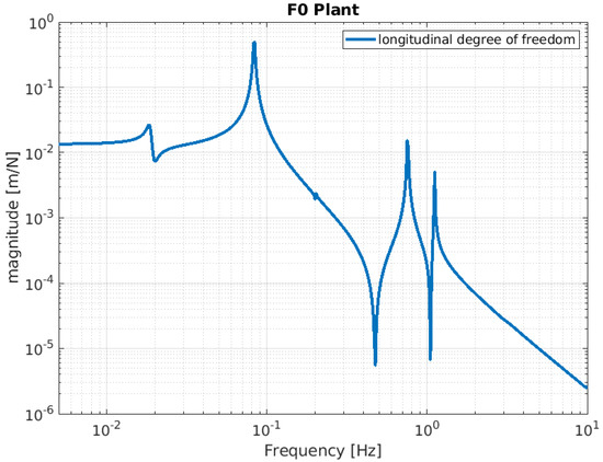
Figure 7.
Simulated F0 mechanical plant. The function is calculated by assuming that a force is injected as input into the F0 stage, with the F0 stage displacement as the output.
3. Expected Behavior of the NIP Prototype
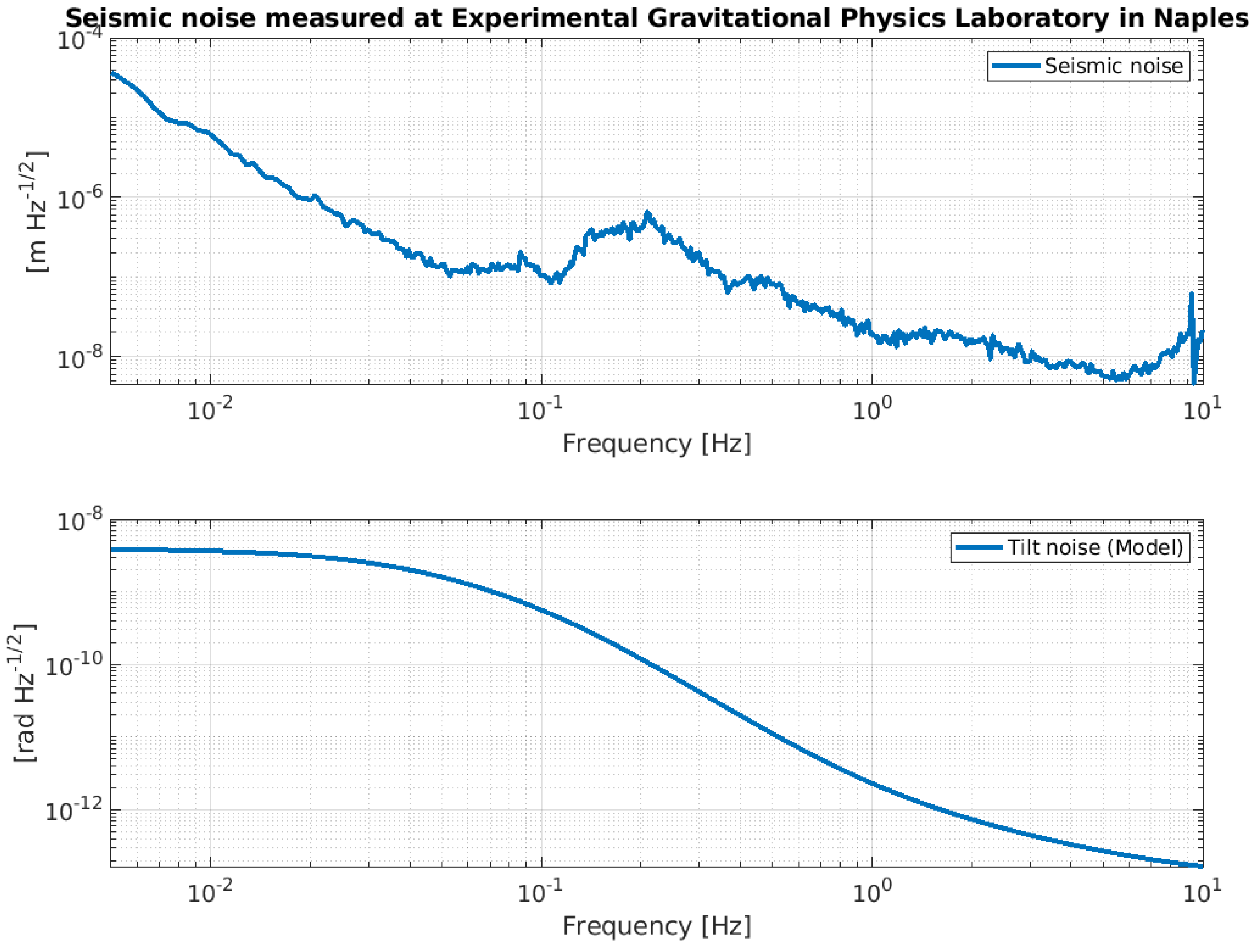
In Section 2, we analyzed a set of transfer functions, which describe the free dynamics of the NIP and provide partial information on its expected performance. However, in order to develop a realistic understanding of the NIP’s performance, it is important to incorporate all the information related to the control strategy into the analysis. This should include details of the noise characteristics of the hardware used to control the system, as well as environmental noise sources (such as microseismic noise and ground tilt). Although the specifics of the control theory are beyond the scope of this paper, it is essential to consider both the control strategy applied to the system and the characteristics of the control hardware in our analysis. This includes both the sensing and actuating devices, as well as the component that defines a linear control, whether analog or digital. In fact, these elements have an impact on the effective performance of the system. It is therefore essential to be able to predict their influence on the behavior of the NIP in order to subsequently identify potential ways to mitigate their effects when this becomes feasible. This necessitates the incorporation of supplementary elements into the simulation model, which are meant to represent the control hardware and the noise characteristics. Figure 8 depicts a seismic profile spectrum, measured in the Laboratory of Experimental Gravitational Physics in Naples, together with a model of ground tilt. Figure 9 shows the noise curves of the sensors and boards that will be installed on the NIP prototype.
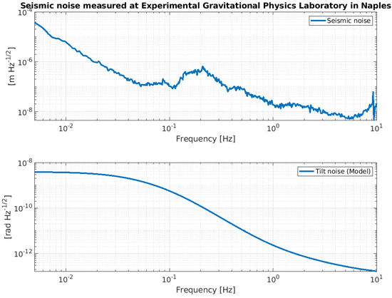
Figure 8.
Amplitude spectral density of the seismic noise displacement measured at the Laboratory of Experimental Gravitational Physics in Naples (upper panel) along with a ground tilt model (lower panel).
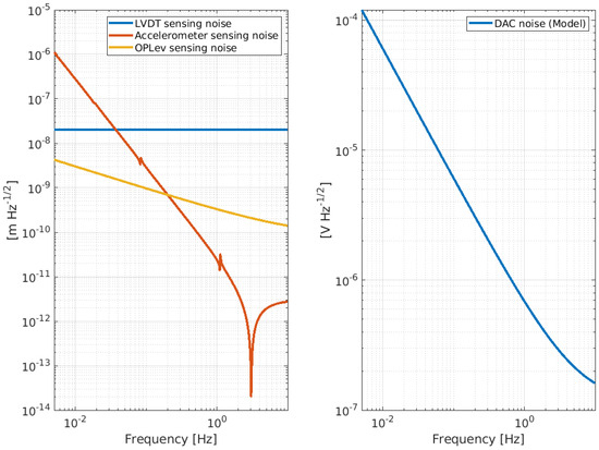
Figure 9.
Amplitude spectral density of the intrinsic noise level of the devices chosen to implement the feedback controls of the NIP. The left panel shows the noise curve of the LVDT (blue curve), accelerometer (red curve), and Oplev (yellow curve). The right panel shows the DAC noise.
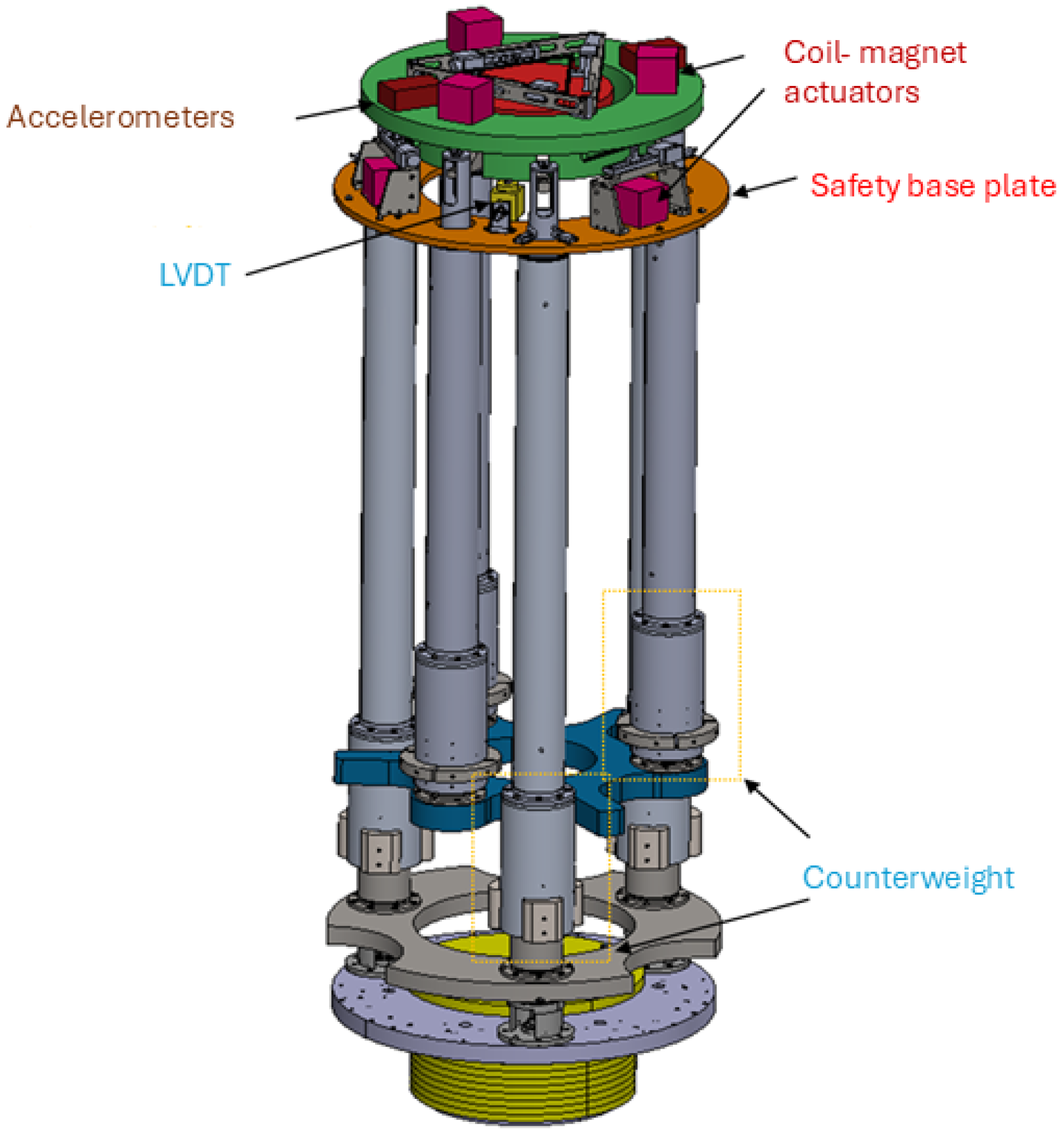
To monitor and damp the internal mode of the NIP in the frequency region [0, 2] Hz, a set of sensors (LVDT, accelerometer, and optical levers [18]) and actuators (coil-magnet actuators) are planned to be installed at the IP level, F0. The sensors are hand-made and the noise curves shown in Figure 9 are the result of fitting the ASD of the noise level measured on the bench. The DAC noise has been extrapolated by the reference curve, provided by National Instruments, into the specification. Figure 10 shows a preliminary CAD of the NIP prototype where the positioning of the sensors and actuators is visible.
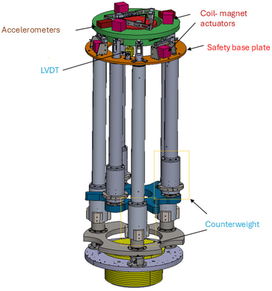
Figure 10.
Technical drawing of the NIP prototype where the position of sensors and actuators are highlighted.
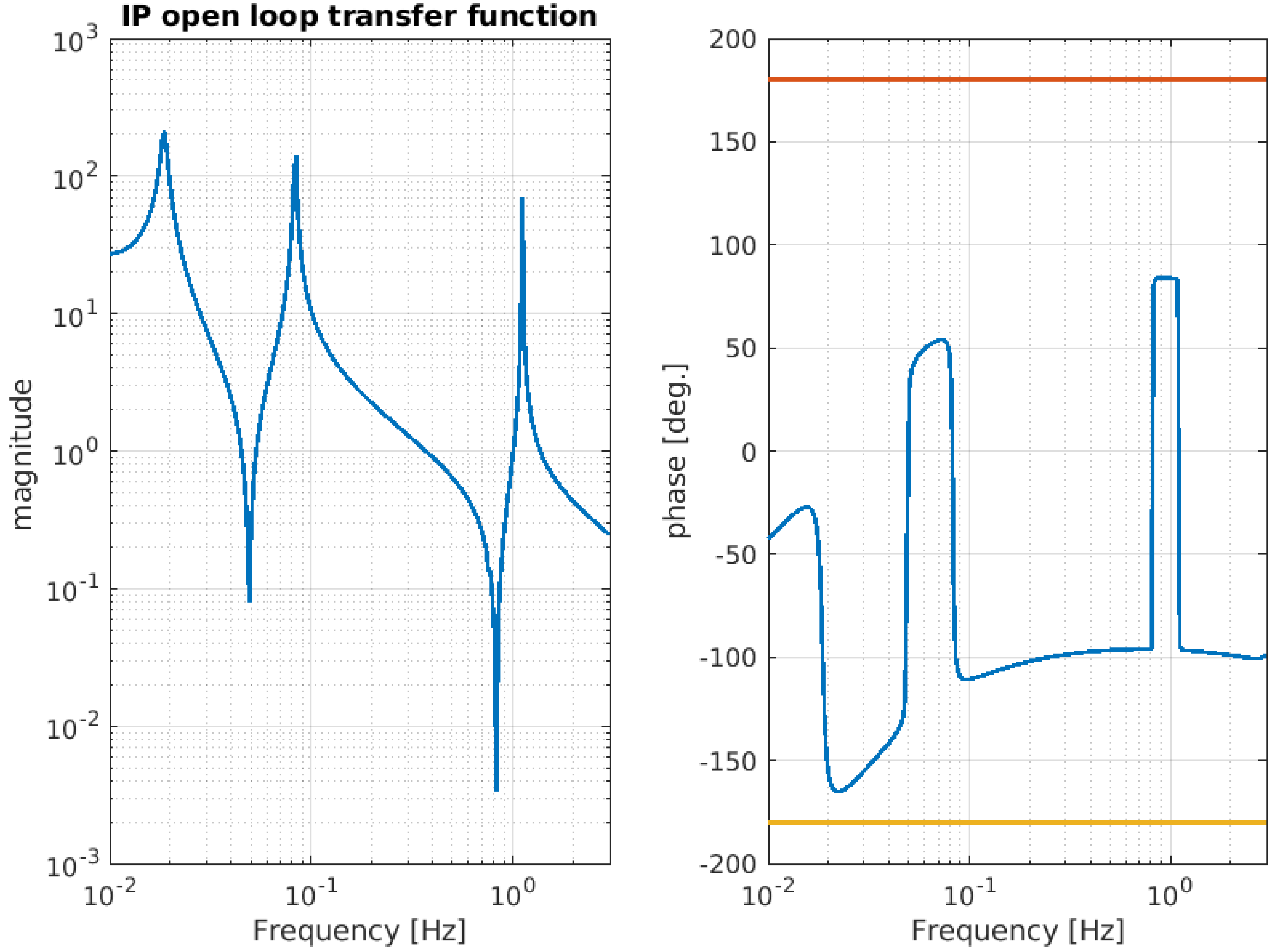
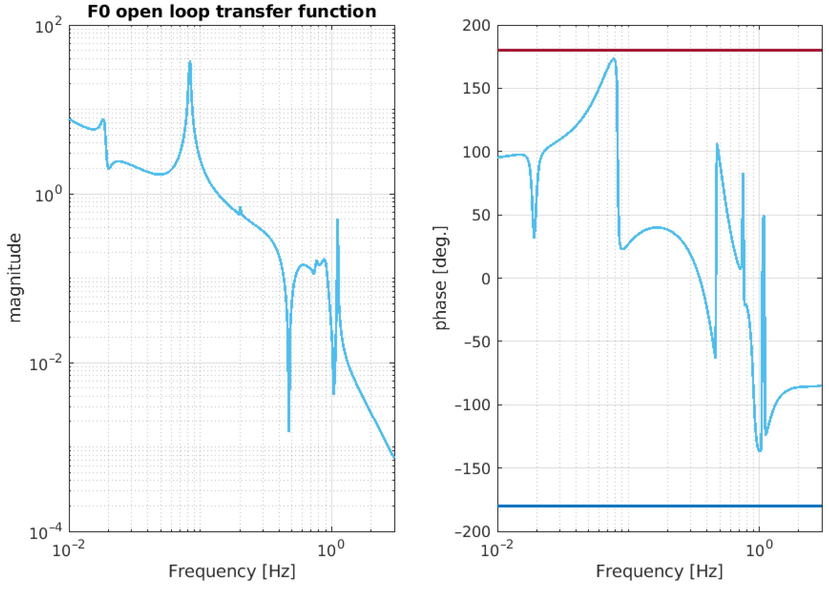
In the OCTOPUS framework, these sensors and actuators can be represented as nodes within the model, while the linear control (a PID designed to be stable) is incorporated as a virtual stiffness (k), represented by an impedance matrix , which is then connected to the stage to be damped (in the case of NIP, the control stages are IP and F0). The control filter is designed by the user to meet stability criteria; in the case of IP and F0, the control filters are PIDs that are used in the [0–2] Hz band. Table 2 and Table 3 show the pole and zero of the aforementioned PIDs controller. Figure 11 and Figure 12 illustrate the open-loop transfer function of the IP and F0 stage, respectively. As can be deduced from the aforementioned figs., the control loops are stable, with the phase of the open loop at unity gain (UGF) far from the instability points (±180 degrees).
Table 2.
Representation in pole and zero format of the PID controller implemented at the IP stage.
Table 3.
Representation in pole and zero format of the PID controller implemented at F0 stage.

Figure 11.
Simulated open-loop transfer function relative to the IP stage. The magnitude of the TF crosses the unity gain at four points: 0.044 Hz, 0.055 Hz, 0.380 Hz, and 1.4 Hz. The phase margin at the crossings ranges approximately from 48 degrees to 132 degrees.
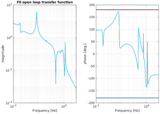
Figure 12.
Simulated open-loop transfer function relative to the the F0 stage. The magnitude of the TF crosses the unity gain at around Hz, with a phase margin of about 140 degrees.
To simulate the behavior of the NIP with and without control loops, it is sufficient to set the dedicated switch in the configuration file to zero or one, according to the desired scenario. Figure 13 illustrates the mechanical attenuation of the NIP at the last stage, when the control loops applied at the IP and F0 stages are turned on and off, respectively.
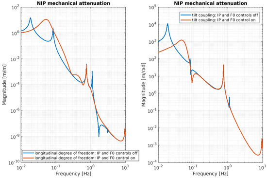
Figure 13.
NIP mechanical attenuation with transfer function from ground MA with F0 and IP control loop active and not active: blue line—simulated passive seismic transmission (open-loop); red line—simulated passive seismic transmission when both IP and F0 control loops are active.
Noise Budget of the NIP
Once the useful transfer functions have been identified, it is possible to estimate the expected performance of the NIP by calculating the ASD of the residual motion of the last stage. One method for determining this is to measure the amount of noise transmitted to the suspended mass from the aforementioned noise sources and identify which noise is limiting the residual motion. This is referred to as a noise budget. The noise curves are passed to the code from an external file and are called up during the calculation for the desired projection. In this context, the ASD of residual motion of the suspended mass can be expressed as a combination of the ASDs of the most relevant noise contributions: sensor noise, DAC noise, ground noise, and tilt noise. Each of these is transmitted to the last stage via the control (IP and F0) or ground branch. Table 4 resumes the noise sources and the channel branch through which they are transmitted to the last stage. Other possible noise sources, like magnetic noise, are completely negligible for the purpose of this work, but could be relevant in a full-size NIP-SA for the impact on the suspended payload.
Table 4.
List of the noise taken into account in the calculation of the noise budget and transfer functions through which they transmit to the suspended mass.
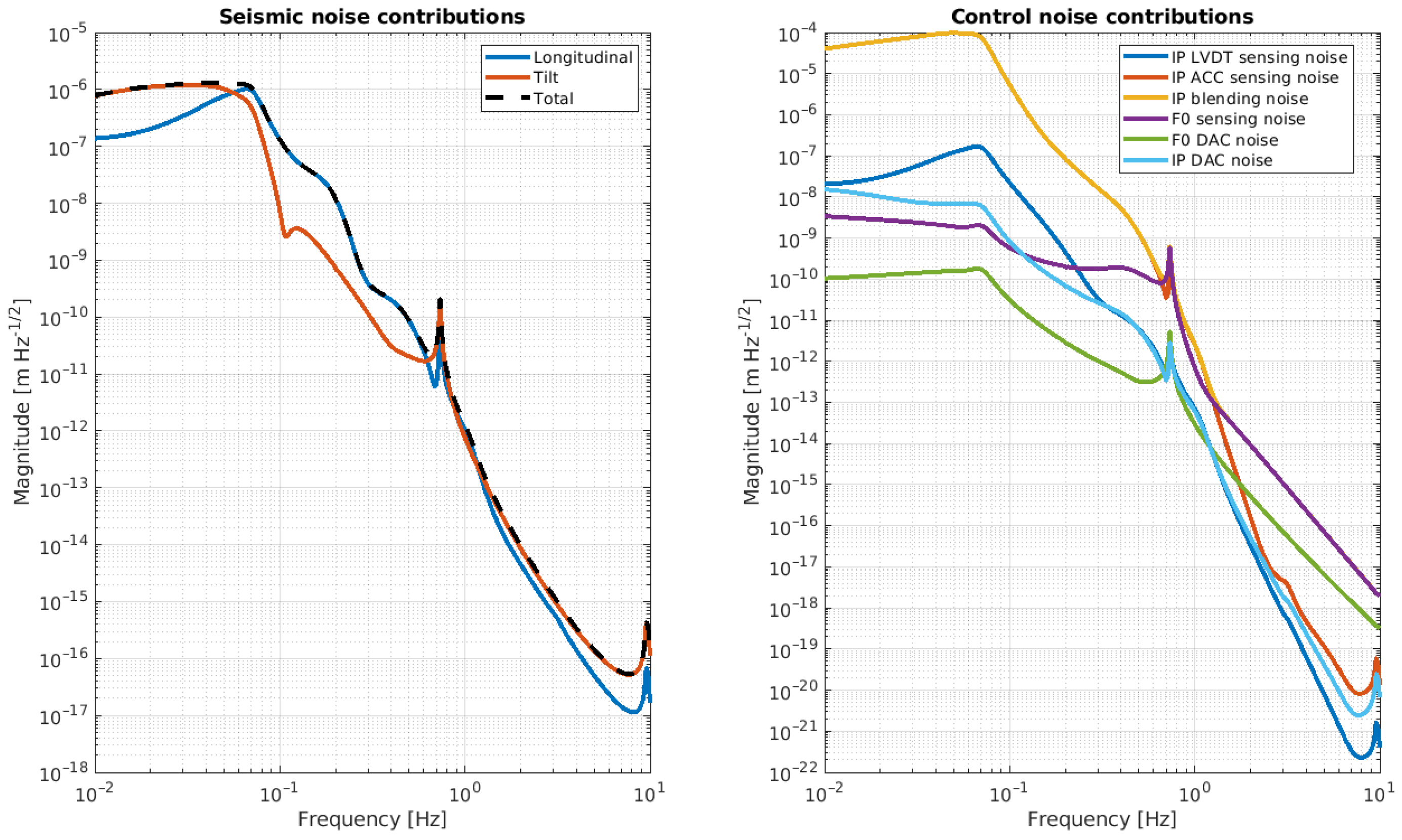
Figure 14 and Figure 15 show the ASD residual motion of the suspended mass due to the noises listed in the Table 4.
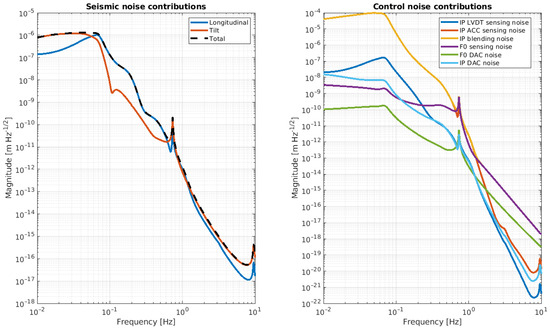
Figure 14.
Noise budget of the NIP prototype. The panel on the left shows the expected residual motion of the suspended mass due to the longitudinal ground motion (blue curve) and ground tilt motion (red curve). The panel on the right shows the expected residual motion of the suspended mass due to the sensing of the accelerometer (red curve), LVDT (blue curve), Oplev (purple curve), and DAC noise (green and ciano curves) re-injected via the control loop.
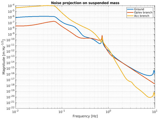
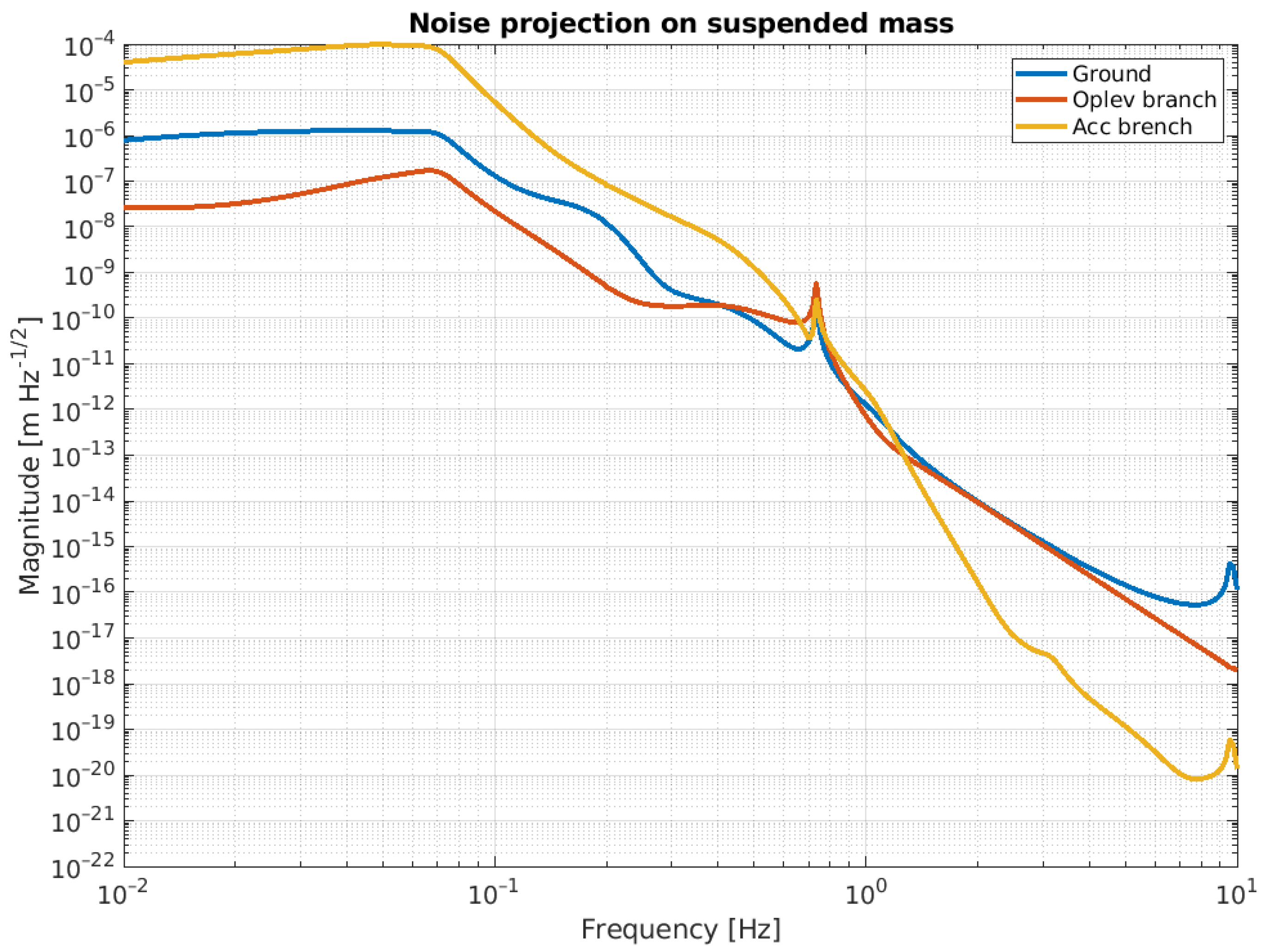
Figure 15.
Noise projection on the suspended mass. Blue curve is the amount of the ground motion re-injected via IP. Red and yellow curves represent the amount of the control noise related to the sensing of the accelerometer and Oplev, respectively, and re-injected via IP and F0 control.
Looking at these plots, it is evident that these noises affect the performance of the NIP in different frequency regions. In line with the noise budget, below 1.5 Hz, the dominant noise source is the sensing noise of the accelerometer, while above this threshold, it is the ground tilt cross-coupling. The ASD of the suspended mass at 2 Hz is in the order of , while at DC (below 0.1 Hz), it is about .
4. Conclusions
This paper summarizes the preliminary results from our simulation studies on an NIP prototype, which is set to be built and tested at the PLaNET Laboratory in Naples. The model has been developed using the impedance matrices formalism and includes a set of sensors and actuators to better reproduce the response of the system for a more realistic performance. The NIP pre-isolation stage offers evident advantages from the point of view of horizontal attenuation, but it has never been implemented, leaving many open questions regarding system stability, automatic control, cross-coupling of different d.o.f., and the problem of tilt noise at ground level. Our study highlights that cross-coupling between tilt and longitudinal directions could be a potential problem if fine-tuning of the parameters is not performed with high accuracy. A further potential limiting factor is the sensing noise of the accelerometer. Indeed, in the frequency band where the feedback control operates (below 1 Hz), this noise is transmitted to the last stage by the IP control branch, thereby spoiling the effective performance of the NIP. One possible way to mitigate this could be to use another inertial sensor with better sensitivity or to redefine the control strategy.
The NIP prototype is currently under construction and it will be tested to check its reliability and performance. The mechanical design of the apparatus and the procurement of the components are progressing well. The assembly and integration process is scheduled to begin in early 2025, depending on the availability of the mechanical components, at the PLaNET laboratory in Naples.
Author Contributions
Conceptualization, P.R. and L.T.; methodology, P.R. and L.T.; software, P.R.; validation, A.B., M.B., F.F., A.G., R.D.R., L.D.F., L.L. and M.N.; formal analysis, A.B., M.B., P.R. and L.T.; investigation, A.B., M.B., L.D.F., P.R. and L.T.; resources, L.D.F., R.D.R. and F.F.; data curation, R.D.R., L.D.F., A.G., P.R. and L.T.; writing original draft, L.T.; writing—review and editing, L.D.F., F.F. and L.T.; visualization, L.T., A.B., M.B., R.D.R., L.D.F., D.D., F.F., A.G., L.L., M.N., F.P., P.P., D.R., P.R., V.S. and F.S. All authors have read and agreed to the published version of the manuscript.
Funding
This research received no external funding.
Data Availability Statement
The data that support the findings of this study are included within the article.
Conflicts of Interest
The authors declare no conflict of interest.
Abbreviations
The following abbreviations are used in this manuscript:
| ASD | Amplitude spectral density |
| DAC | Digital-to-analog converter |
| ET | Einstein Telescope |
| IP | Inverted pendulum |
| LVDT | Linear variable displacement transducer |
| OpLev | Optical levers |
| NIP | Nested inverted pendulum |
| SA | Super-attenuator |
References
- Trozzo, L.; Badaracco, F. Seismic and Newtonian Noise in the GW Detectors. Galaxies 2022, 10, 20. [Google Scholar] [CrossRef]
- ET Steering Committee Editorial Team. Design Report Update 2020 for the Einstein Telescope. Available online: https://gwic.ligo.org/3Gsubcomm/docs/ET-0007B-20_ETDesignReportUpdate2020.pdf (accessed on 1 December 2024).
- Hild, S.; Abernathy, M.; Acernese, F.E.; Amaro-Seoane, P.; Andersson, N.; Arun, K.; Barone, F.; Barr, B.; Barsuglia, M.; Beker, M.; et al. Sensitivity studies for third generation gravitational waves observatories. Class. Quantum Gravity 2011, 28, 094013. [Google Scholar] [CrossRef]
- Update on Suspension Design for Advanced LIGO. 2012. Available online: https://dcc.ligo.org/public/0001/G0900367/002/G0900367v2.pdf (accessed on 1 December 2024).
- Matichard, F.; Lantz, B.; Mittleman, R.; Mason, K.; Kissel, J.; Abbott, B.; Biscans, S.; McIver, J.; Abbott, R.; Abbott, S.; et al. Seismic isolation of Advanced LIGO: Review of strategy, instrumentation and performance. Class. Quantum Gravity 2015, 32, 185003. [Google Scholar] [CrossRef]
- Robertson, N.A.; Cagnoli, G.; Crooks, D.R.M.; Elliffe, E.; Faller, J.E.; Fritschel, P.; Goßler, S.; Grant, A.; Heptonstall, A.; Hough, J.; et al. Quadruple suspension design for Advanced LIGO. Class. Quantum Gravity 2002, 19, 4043. [Google Scholar] [CrossRef]
- Driggers, J.C.; Evans, M.; Pepper, K.; Adhikari, R. Active noise cancellation in a suspended interferometer. Rev. Sci. Instrum. 2019, 83, 024501. [Google Scholar] [CrossRef] [PubMed]
- Driggers, J.C.; Vitale, S.; Lundgren, A.P.; Evans, M.; Kawabe, K.; Dwyer, S.E.; Izumi, K.; Schofield, R.M.; Effler, A.; Sigg, D.; et al. Improving astrophysical parameter estimation via offline noise subtraction for Advanced LIGO. Phys. Rev. D 2019, 99, 042001. [Google Scholar] [CrossRef]
- DeRosa, R.; Driggers, J.C.; Atkinson, D.; Miao, H.; Frolov, V.; Landry, M.; Giaime, J.A.; Adhikari, R.X. Global feed-forward vibration isolation in a km scale interferometer. Class. Quantum Gravity 2012, 29, 215008. [Google Scholar] [CrossRef]
- Giaime, J.A.; Daw, E.J.; Weitz, M.; Adhikari, R.; Fritschel, P.; Abbott, R.; Bork, R.; Heefner, J. Feedforward reduction of the microseism disturbance in a long-base-line interferometric gravitational-wave detector. Rev. Sci. Instrum. 2003, 74, 218–224. [Google Scholar] [CrossRef]
- Akutsu, T.; Ando, M.; Arai, K.; Arai, Y.; Araki, S.; Araya, A.; Aritomi, N.; Aso, Y.; Bae, S.; Bae, Y.; et al. Overview of KAGRA: Detector design and construction history. Prog. Theor. Exp. Phys. 2021, 74, 05A101. [Google Scholar] [CrossRef]
- Ballardin, G.; Bracci, L.; Braccini, S.; Bradaschia, C.; Casciano, C.; Calamai, G.; Cavalieri, R.; Cecchi, R.; Cella, G.; Cuoco, E.; et al. Measurement of the Virgo Superattenuator performance for seismic noise suppression. Rev. Sci. Instrum. 2001, 72, 3643–3652. [Google Scholar] [CrossRef]
- Acernese, F.; Antonucci, F.; Aoudia, S.; Arun, K.G.; Astone, P.; Ballardin, G.; Barone, F.; Barsuglia, M.; Bauer, T.S.; Beker, M.G.; et al. Measurements of Superattenuator seismic isolation by Virgo interferometer. Astropart. Phys. 2010, 33, 182–189. [Google Scholar] [CrossRef]
- Trozzo, L. Low Frequency Optimization and Performance of Advanced Virgo Seismic Isolation System. Ph.D. Thesis, Università di Siena, Siena, Italy, 2018. [Google Scholar]
- Bertocco, A.; Bruno, M.; De Rosa, R.; Di Fiore, L.; D’Urso, D.; Frasconi, F.; Gennai, A.; Lucchesi, L.; Refat, M.; Pilo, F.; et al. New Generation of Superattenuator for Einstein Telescope: Preliminary studies. Class. Quantum Gravity 2024, 41, 117004. [Google Scholar] [CrossRef]
- Ruggi, P.; Pinto, M.; Trozzo, L.; Cella, G.; Losurdo, G.; Chessa, P.; Longo, A.; Vicerè, A.; MAjorana, E. A mechanical simulation tool based on impedance matrices. Phys. Rev. D, submitted to PRD and under review.
- Bove, A.; Di Fiore, L.; Calloni, E.; Grado, A. Optimization of multi-pendular seismic suspensions for interferometric gravitational-wave detectors. Europhys. Lett. 1997, 40, 601–606. [Google Scholar] [CrossRef]
- De Rosa, R.; Di Fiore, L.; Garufi, F.; Grado, A.; La Rana, A.; Milano, L. An optical readout system for the drag free control of the LISA spacecraft. Astropart. Phys. 2011, 34, 394–400. [Google Scholar] [CrossRef]


Disclaimer/Publisher’s Note: The statements, opinions and data contained in all publications are solely those of the individual author(s) and contributor(s) and not of MDPI and/or the editor(s). MDPI and/or the editor(s) disclaim responsibility for any injury to people or property resulting from any ideas, methods, instructions or products referred to in the content. |
© 2025 by the authors. Licensee MDPI, Basel, Switzerland. This article is an open access article distributed under the terms and conditions of the Creative Commons Attribution (CC BY) license (https://creativecommons.org/licenses/by/4.0/).