2. Basic Theory of Wheel/Rail Rolling Contact
The basic theories of wheel–rail rolling contact mainly include the classical theoretical models of wheel–rail in rolling contact and the numerical theories and numerical methods developed in modern times. There are five classical theoretical models which reflect the relation between the total force components and the creepage components between wheel and rail in rolling contact state. The first is the one-dimensional rolling contact model of wheel–rail published by F. W. Carter in 1926, which describes the nonlinear relation law between the longitudinal creepage and the longitudinal creep force in the direction of wheel–rail rolling [
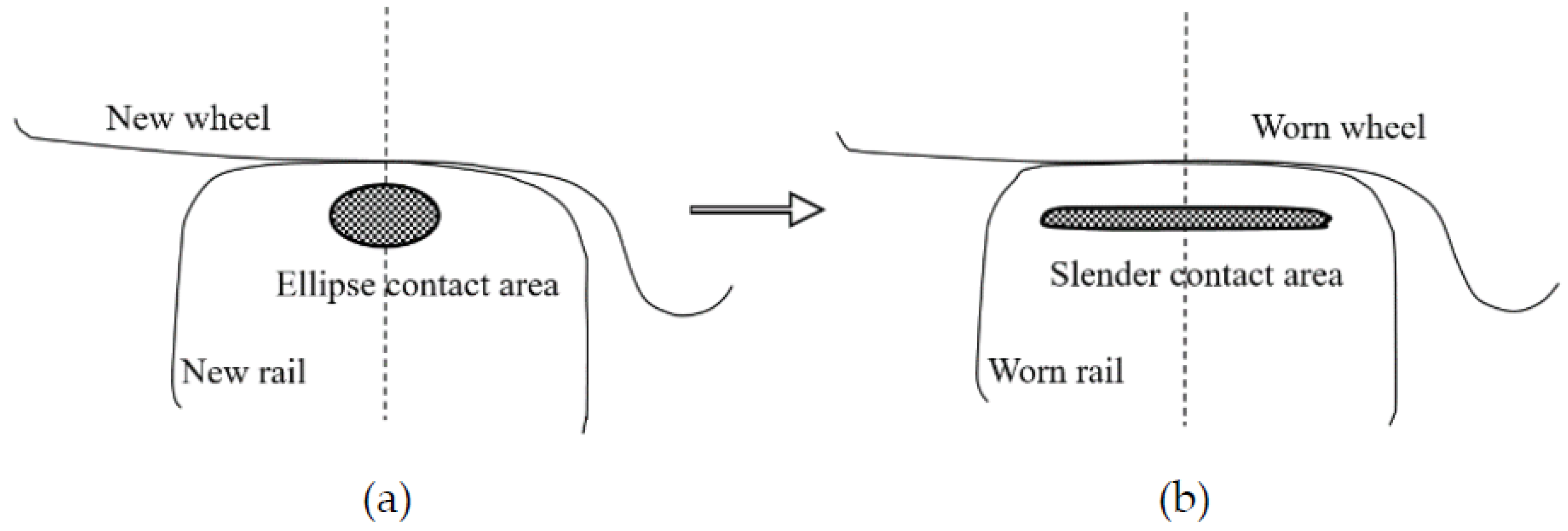
17]. The model is suitable for wheel/rail contact surfaces with such severe wear, which causes the wheel–rail contact patch to become elongated laterally, as shown in
Figure 1.
Figure 1a indicates that the new wheel and the new rail contact, forming an elliptical contact spot. After long-term operation, the wheel–rail contact surface is seriously worn, and the contact spot formed becomes lateral slender strips, as shown in
Figure 1b. The model is still used in evaluating adhesion and traction between the locomotive wheel and rail [
18]. The important theoretical contribution of F. W. Carter’s model is that it adopted the two hypotheses, one being that the sliding of the wheel–rail contact surfaces starts from the rear edge of the contact patch and gradually expands to the front edge of the contact patch with the increase in the longitudinal creepage.
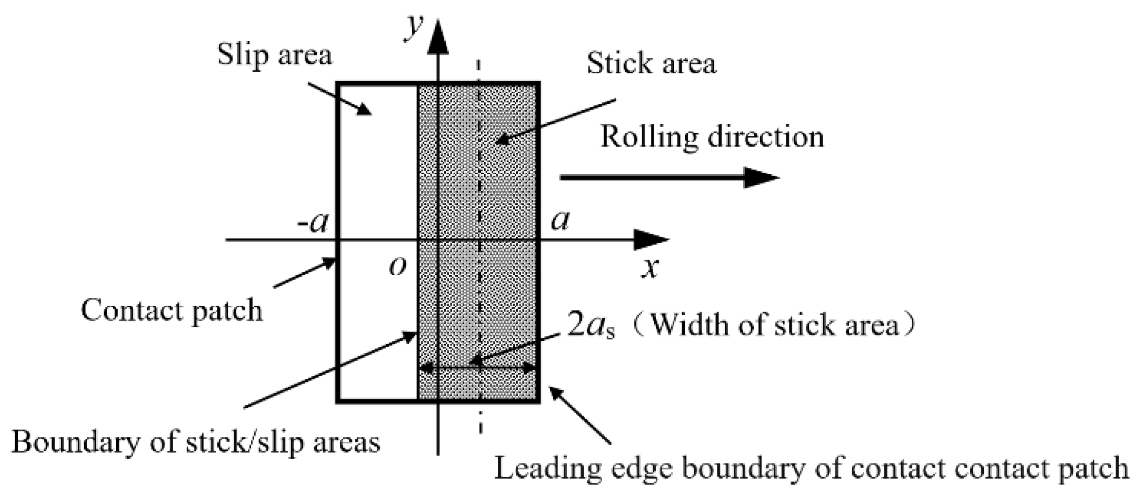
Figure 2 shows the division of the slip–slip area of the wheel–rail rectangular contact patch, first established by Carter. The rectangular contact patch approximates the laterally elongated contact patch in
Figure 1b. This hypothesis was verified to be correct using some numerical methods later [
3,
19]. The other contribution of the model is that the longitudinal width ratio of the adhesive zone to the whole contact area is a function of the ratio of the longitudinal creep force to the maximum total friction force in the contact patch, which is a mathematical analytic expression, as indicated by Equation (2). In Equation (2),
and
are the semi-axial lengths of longitudinal width of the contact patch and the adhesion zone, respectively,
is the longitudinal creep force of the wheel/rail,
is the total normal load and
is the friction coefficient at the wheel–rail interface. The two hypotheses of this model were adopted in subsequent studies on the wheel–rail rolling contact models based on Hertz theory [
3].
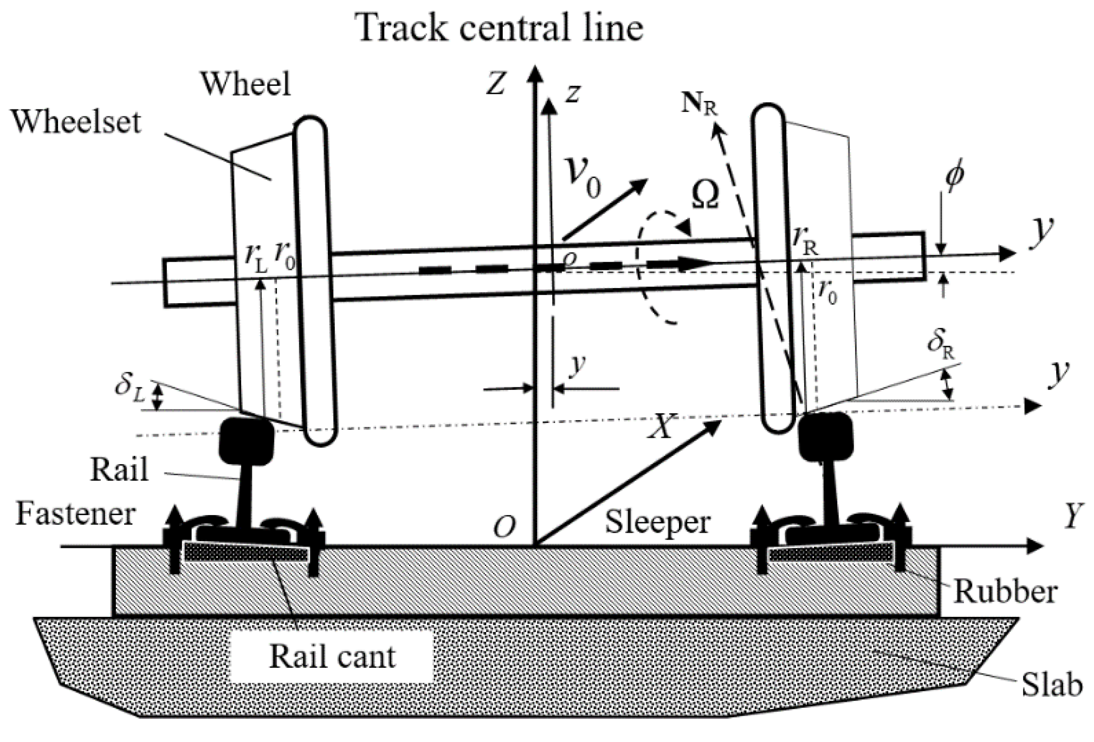
Vermeulen and Johnson developed a model of wheel–rail in rolling contact based on Carter’s research ideas. Their model is the mathematical analytical formula expressing the nonlinear relation between longitudinal/lateral creepages and forces. This model ignores the influence of wheel–rail spin creepage [
20]. The relative rotation between wheel–rail interface is caused by the projection of the rolling angular velocity of the wheelset,
, onto the normal direction at wheel/rail contact points, as indicated in
Figure 3. In the Figure,
is the normal direction at the right wheel/rail contact point. The direction of
always coincides with the axis of the wheelset. It is at angles of
and
with the common normal directions at the right and left wheel/rail contact points, respectively.
and
are, respectively, the left and right wheel/rail contact angles, and
is the rolling angle of the wheelset. The projections of
onto the normal directions rely on them. The ratios of the projection to wheelset running speed,
, is defined as the wheel–rail spin creepage. The spin creepage has great influence on the amplitudes of longitudinal and lateral creep forces of wheel–rail and their density distribution direction [
3]. The shapes of the wheel–rail contact patch and stick zone in it considered in this theoretical model are ellipsoids, as indicated by
Figure 4.
It is not correct to treat the two local areas symmetrical in the direction of rolling as sliding areas [
3]. The areas are denoted by A
1 and A
2 in
Figure 4. They are next to the leading edge of the elliptical contact patch. Especially for trains running on a tangent track, the model can effectively consider the lateral and longitudinal coupling of the wheel–rail system and carry out the rapid dynamic behavior simulation of large vehicle-track coupling system. However, when a train runs on a curved track, the outer wheel rim will contact the inner corner of the outer rail and in this case, the wheel–rail contact angle is large. The larger the wheel–rail contact angle, the greater the spin creepage between the wheel and rail, the greater the influence on the longitudinal and lateral creep forces of the wheel and rail and the greater the error of the dynamics simulation results [
3]. This is because the model does not consider the influence of wheel/rail spin creepage on the wheel/rail creep forces.
In 1967, J.J. Kalker developed a linear wheel–rail creep theoretical model considering the effect of small spin creepage by means of series theory in his doctoral thesis, which established the linear relation laws of longitudinal and lateral creepages/creep forces, spin creepages/spin-moments of the wheel/rail [
21]. Because Kalker could not introduce Coulomb’s Friction Limitation Law when deducing the theoretical model, his linear creep-force theory reflects that wheel–rail creep-force increase can be unrestricted with the increase in wheel–rail creepage, which does not conform to Coulomb’s Friction Law. It should be noted that it is only suitable for small creepage cases when applied [
3].
By means of Vermeulen–Johnson’s model and Kalker’s linear model, Z.Y. Shen et al. developed a three-dimensional nonlinear wheel–rail creepage/creep-force model, considering the influence of the small spin creepage [
22]. It is emphasized that the model is suitable for wheel–rail rolling contact with the small spin creepage, that is, the case of a small wheel–rail contact angle. This requirement indicates that there may be a certain error in analyzing wheel–rail rolling contact behavior by using this model when a train is running on sharp curved tracks. This is because the wheel flange contacts the inner corner of the outer rail.
The fifth classic wheel–rail creep theoretical model is called the simplified theoretical model (hereinafter, referred to as FASTSIM) developed by J.J. Kalker. It was developed with the help of the linear model of Kalker [
23]. In this model it is assumed that the normal force distribution in the wheel/rail contact patch is in harmony with the clearance between the wheel/rail at contact point. The clearance is a mathematical expression for a quadratic paraboloid. The normal pressure distribution in the contact patch is no longer an ellipsoid distribution form, but a quadratic parabolic distribution form. This is different from the wheel/rail normal pressure distribution considered in the establishment of the four classical Hertzian creepage/creep-force models discussed above. In the FASTSIM, it is assumed that the three surface force components in the contact patch have a linear relationship with the corresponding three displacement components in the contact patch and the coupling effect of them is ignored. This model can be used to calculate not only the creep forces of the wheel/rail, but also the distribution of the slip and tangential forces in the elliptical contact patch. However, the calculation speed is lower than that of the previous four theoretical models.
It is worth noting that establishing the above five theoretical models relies on the Hertz contact theory hypothesis, so they are called the Hertzian calculation models. These models do not include the influence of wheelset running speed explicitly, although the creepage is defined as the ratio of the speed difference at the wheel–rail contact interface to wheelset speed. However, at present, the dynamic behavior simulation of the large vehicle-track coupling system still relies on the models discussed above, regardless of train operating speeds. The Hertz contact theory hypothesis includes that the contacting surfaces of two bodies in contact are smooth, their material is within elastic range and the radius of curvature at or near the contact point is much larger than the characteristic radii of the contact patch. It is difficult to strictly meet the Hertz theory hypothesis in the actual operation state of wheel and rail. The neglected factors (such as the normal and abnormal irregularities of wheel–rail contact surfaces, the actual geometries of wheel/rail, plastic deformation, etc.) may have an influence on the coupling dynamic behavior of the vehicle-track system to a certain extent. However, their influence on the local behavior of wheel/rail (such as wear, elastoplastic deformation, rolling contact fatigue, adhesion and wheel/rail noise) cannot be ignored, especially in severe cases, such as rail corrugation, wheel polygonal wear, rail welded joints, wheel/rail scratch, contact surface flaking, etc. It is impossible to analyze the effects of these factors by using these models [
24,
25,
26,
27]. It is necessary to develop more advanced wheel–rail rolling contact models and corresponding numerical methods to consider the influence of the above factors on wheel–rail rolling contact behavior.
Modern wheel–rail rolling contact theories and corresponding numerical methods are developing. In the 1970s, J.J. Kalker expressed the rolling contact problem of two elastic bodies with friction by using the variational inequality according to the variational principle. The solution of the rolling contact problem was determined by solving the force density components on the contact patch, satisfying the minimum residual energy principle of two elastic contact bodies [
28]. The corresponding numerical program is called CONTACT, which has been widely used by railways around the world to analyze wheel–rail rolling contact behavior. This theoretical model breaks through the assumptions of Hertz contact theory. So, it is called the Non-Hertz rolling contact theory model. The program can be used to calculate the relevant information of wheel/rail in rolling contact, some of which cannot be calculated by the above five classical wheel/rail rolling contact theoretical models. For example, the true shape of the wheel/rail contact patch after wear, stick–slip areas in the contact patch, the amplitude and direction distribution of tangential force components, normal pressure, distributed slip and stress field in wheel/rail body, etc. [
3]. They are useful in the analysis of wheel–rail fatigue and rolling contact noise. However, compared with the classical creep-force models above, its calculation speed is much slower. It is not suitable for fast simulation analysis of dynamic behavior of the large-scaled vehicle-track coupling system. Its numerical realization process is based on the theory of elasticity in half-space, and the numerical results of wheel–rail normal force are slightly larger than those of the current finite element model [
29,
30]. This is because wheel and rail are regarded as elastic half-space objects, which actually exaggerates the contact stiffness of wheel–rail. The influence of wheel–rail contact on plastic deformation should not be neglected [
30].
X.S. Jin et al. made a detailed analysis and comparison of the numerical analysis results of wheel/rail in rolling contact by using the five above calculation models (Carter’s model not included). In the analysis, the wheel–rail motion states considered are general and representative. The numerical results showed that, except for Kalker’s linear theoretical model, the approximation degree of the results of the other models is acceptable [
3]. Considering the need for rapid numerical simulation of the vehicle-track coupling dynamics, especially for high-speed train or vehicle-track coupling dynamics, the wheel–rail creepage/creep-force model proposed by Z.Y. Shen et al. not only considers the influencing of the longitudinal, lateral and spin creepages, but also has high computational efficiency, because it is an analytical expression. Even in the case of wheel rim in contact with rail gauge corner, that is, for the large wheel/rail contact angle or the large spin creepage, there is little difference between the calculation results of Shen’s model and CONTACT. Later, X.S. Jin et al. further improved Kalker’s CONTACT model by using the finite element method [
3,
31,
32], and the improved model could take into account the influence of the outer boundary conditions of the wheel–rail contact point on wheel/rail rolling contact behavior. However, it is a pity that the theoretical model has not realized numerical calculation.
By means of the parametric variational principle quadratic programming method and finite element method, the calculation method developed by W.X. Zhong and H.W. Zhang can be used to analyze the wheel–rail elasto-plastic contact problem [
33]. The parametric variational principle is more widely used than the classical variational principle. It can avoid the Drucker hypothesis used in material plasticity theory and effectively deal with the problem of irreversible flow of elasto-plastic materials and friction contact with sliding. This method was successfully used to analyze wheel–rail elastoplastic rolling contact behavior in transient braking and driving of a wheel rolling on a rail [
34].
Since the 1980s, the finite element method has been used to analyze wheel–rail rolling contact behavior. In the early stages, the wheel–rail contact finite element model is relatively simple [
35,
36]. Oden and Lin proposed an analytical expression to represent a two-dimensional rolling contact problem. Later, the two-dimensional analytical solution was extended to the three-dimensional case [
37,
38]. Nachenhorst Udo introduced stick–slip contact control conditions in his doctoral thesis [
39], the fluid layout gradient decomposition method and the Arbitrary Lagrange–Euler Method were used to analyze the rolling contact behavior of 3D elastic bodies, and the fine mesh adaptive technique was used in the analysis. His numerical method was used to solve the steady rolling contact problem of three-dimensional elastic bodies. The considered rolling speed is low (10 km/h), and the contact surfaces are smooth without sliding between them [
40].
In the service process of wheel–rail, the wheel and rail experiences repeated acceleration and deceleration, wheel/rail running surfaces exhibiting various defects, such as cracks, surface material stripping and uneven wear. The wheel–rail rolling contact process is a transient elastoplastic rolling contact behavior with the operation speed changing. Namely, the rolling contact behavior varies with the operation speed and time. In these cases, the rolling contact theories discussed above cannot be used to clearly explain the wheel–rail rolling contact behavior and corresponding mechanism problems. The wheel/rail rolling contact model established based on the finite element method can consider more factors discussed above.
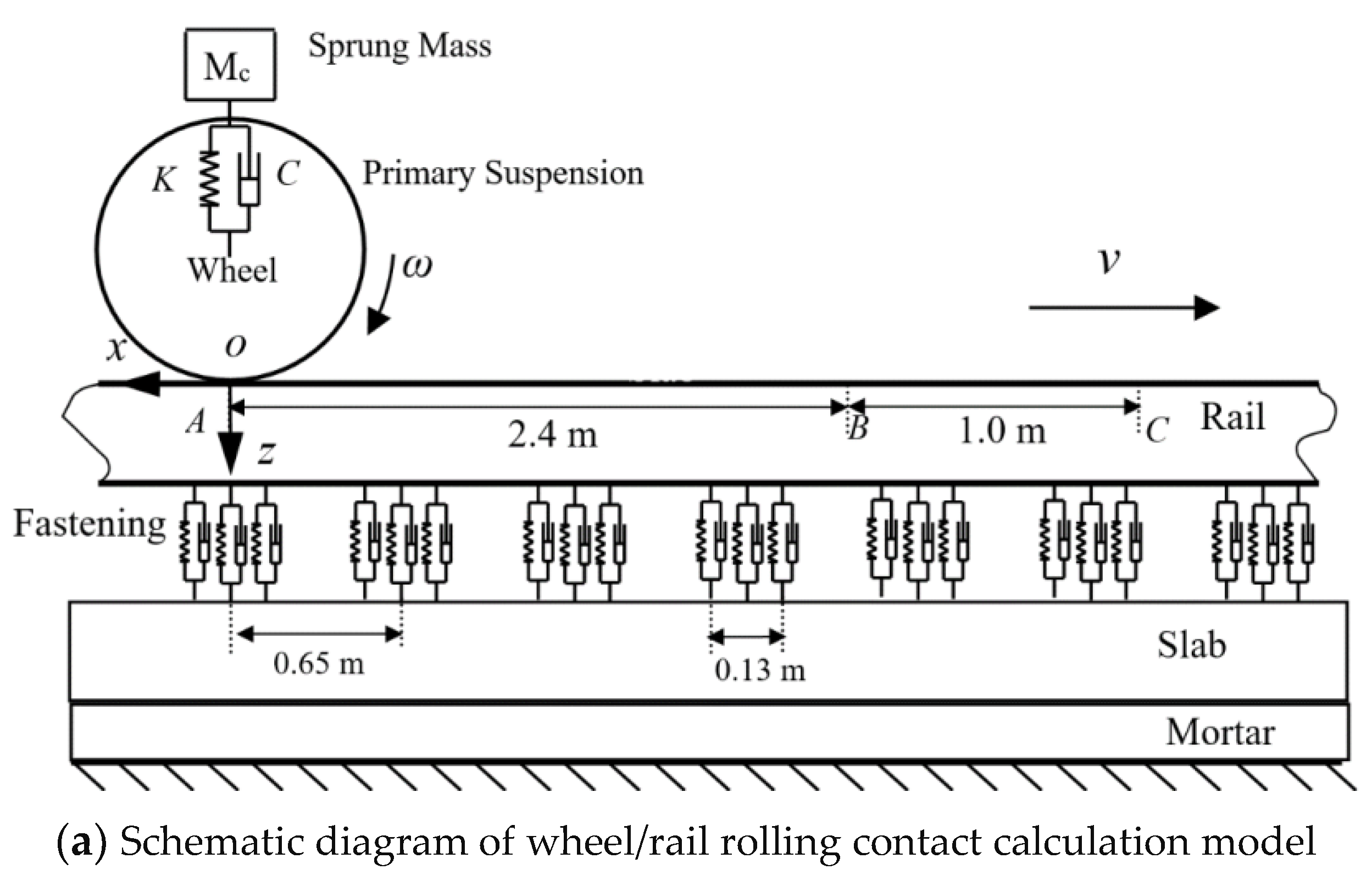
With the help of commercial software ANSYS/LS-DYNA, X. Zhao and Z.L. Li developed a three-dimensional elasto-plastic model of wheel–rail in rolling contact [
29,
30], and analyzed the wheel–rail impact behavior caused by rail squat [
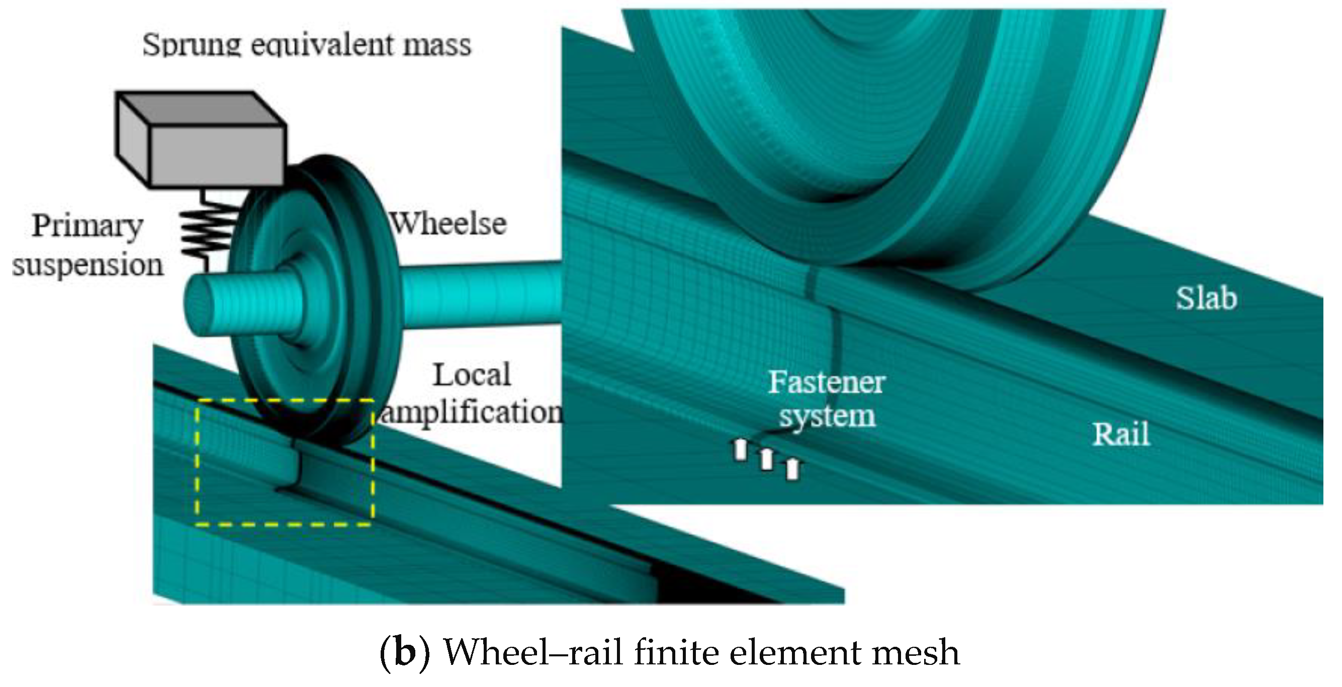
41]. In their model, the actual geometric dimensions of wheel and rail, the unsprung mass of the vehicle and the parameter characteristics of the track are taken into account. The wheel rolling speed is 40–140 km/h, and the wheel–rail contact boundary model adopts the face-to-face contact element method. Based on their model, a high-speed wheel–rail 3D elastoplastic finite element model was developed, as shown in
Figure 5. This model also takes into account the actual dimensions of the track (rails, fasteners, sleepers and track plates, as well as mortar lay and the sprung mass of the wheel) [
30,
42].
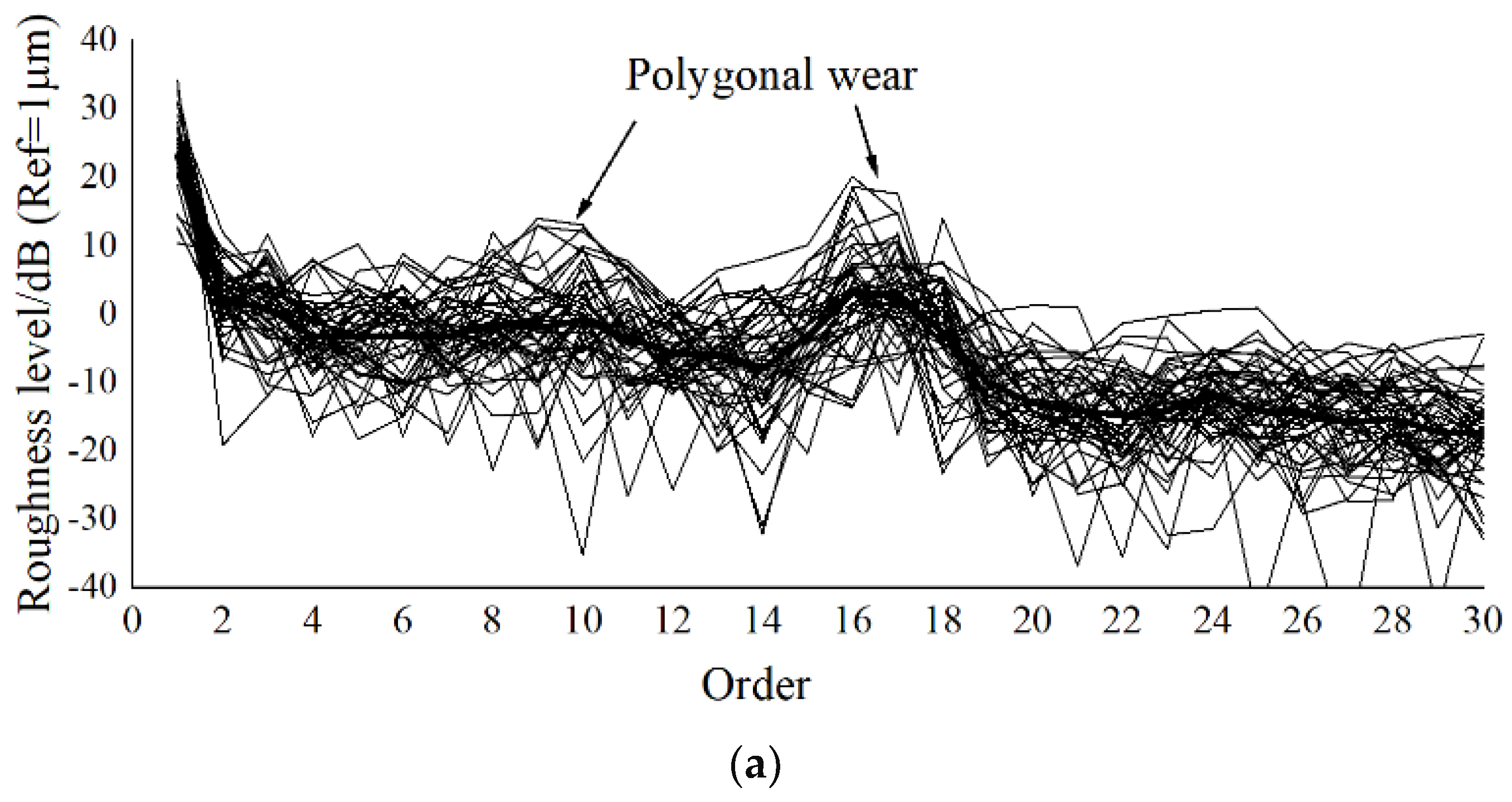
The model is used to analyze the influence of many factors on high-speed wheel–rail rolling contact behavior successfully and effectively. These factors include rail corrugation, crack, wheel polygon wear, scratch, material inclusion, high speed, etc. The numerical results with important reference values are obtained. These results can effectively help us to clarify the evolution process and causes of the concerned wheel/rail damage state in high-speed operations. It provides important guidance for improving wheel/rail material, wheel/rail production technology and wheel/rail maintenance strategy and ensuring safe operation of trains at high speeds.
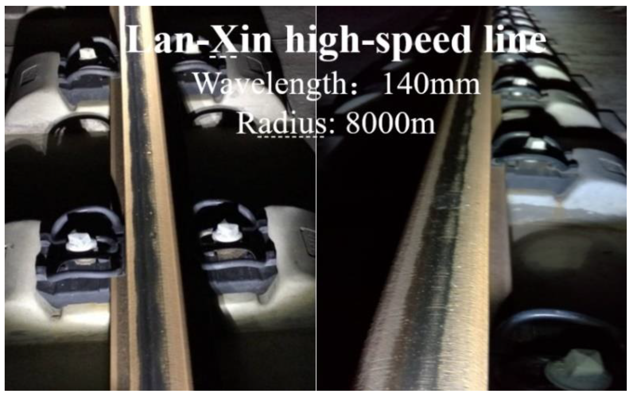
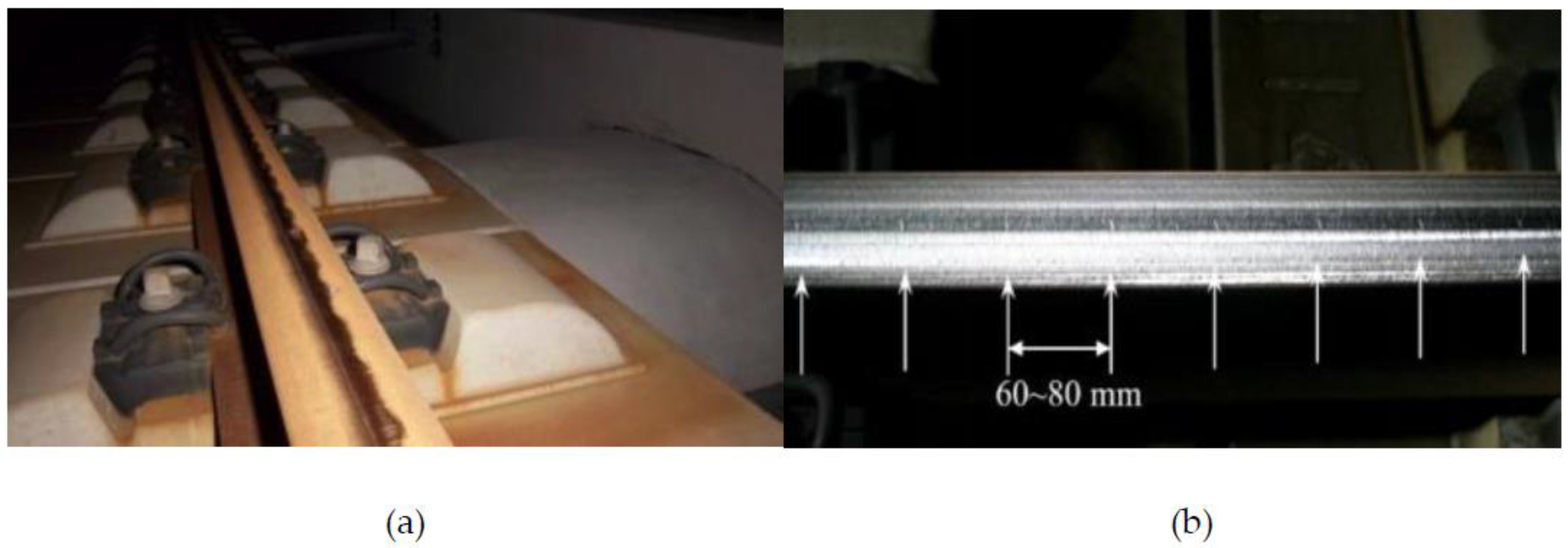
Since the operation of the high-speed railway in China, rail corrugation occurred in some rail lines [
16], as shown in
Figure 6. The additional dynamic loads caused by rail corrugation with different wavelengths, depths and operating speeds need to be further understood. They are the basis for evaluating high-speed safe operation, key component fatigue life assessment and maintenance strategy formulation. However, the current instrumented wheelset for measuring dynamic wheel–rail loads cannot accurately measure high-frequency additional dynamic loads between the wheel and rail (500–1100 Hz [
16]) under the excitation of rail corrugation. A numerical method is still the only way to calculate the actual dynamic load between the wheel and rail in a high-frequency range.
Figure 7 shows the maximum and minimum values of the wheel/rail vertical dynamic load at an operating speed of 300 km/h which varies as the depth of rail corrugation with 60mm wavelength increases. The black lines in
Figure 7 represent the calculation results, obtained by using a traditional vehicle-track coupling system dynamics model. The red lines represent the results of the current three-dimensional finite element model of wheel–rail. Obviously, the calculation results of the two models are different. The amplitudes of fluctuation of the additional dynamical load, calculated by using the traditional dynamic model, are much larger than those calculated by the elasto-plastic finite element model. This is because in the wheel–rail normal direction, the traditional dynamics model uses the Hertz contact model to couple the vehicle subsystem with the track subsystem [
43]. The calculation results of it show that the wheel/rail vertical dynamic load is exaggerated. The reason is that the elastic half-space hypothesis in Hertz contact theory overstates the actual wheel/rail contact stiffness [
3].
Another important phenomenon, as seen in
Figure 7, is the case where some of the minimum wheel–rail dynamic loads are zero, which indicates that the wheel has separated from the rail. Too long of a wheel–rail separation time in high-speed operation will pose a threat to safe running. The length of separation time is strictly limited [
43]. The additional dynamic load difference calculated by the two models has a great influence on the evaluation of the operation safety index, the service life of the concerned components and developing the maintenance strategy of wheel and rail. It is worth further discussion.
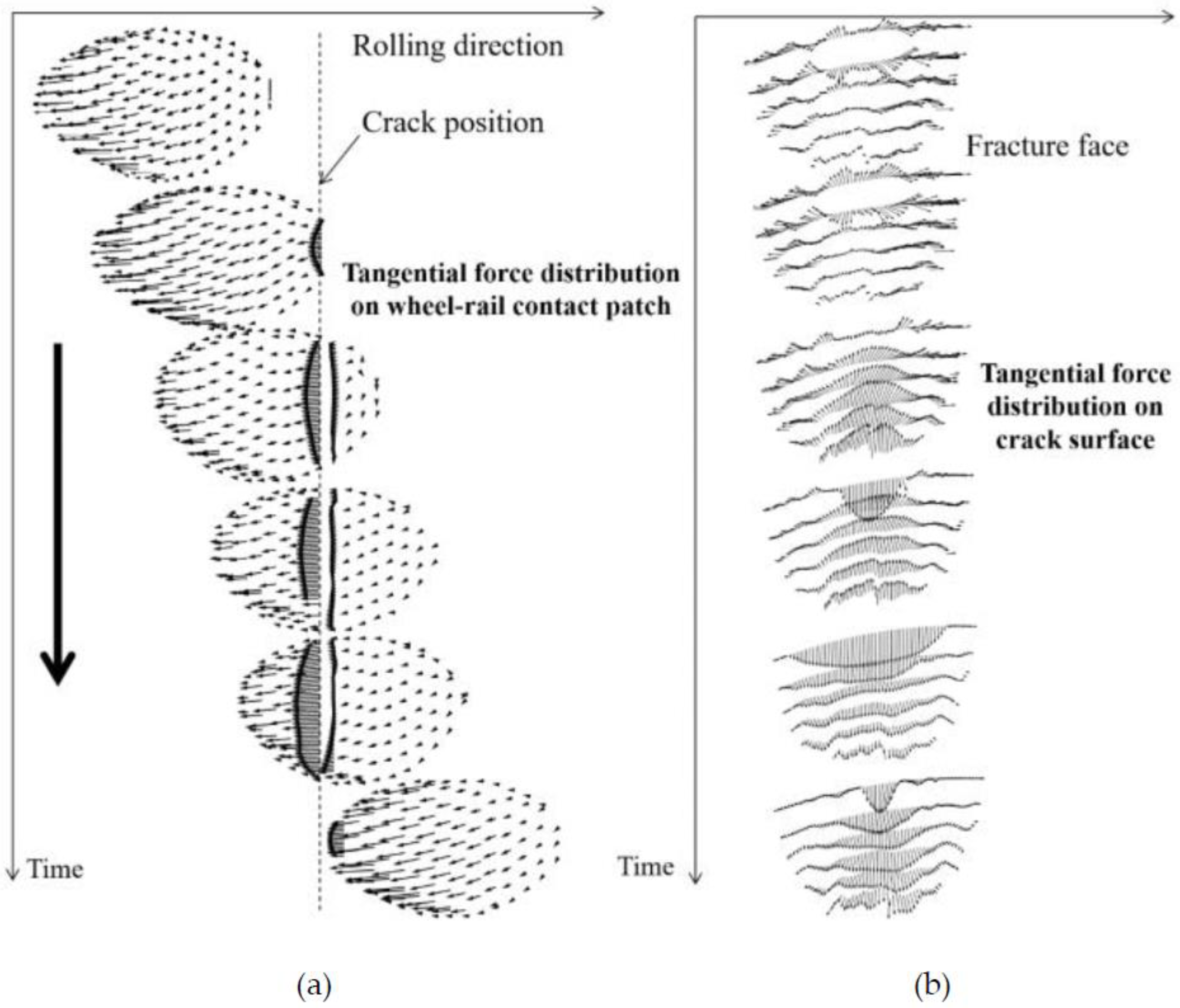
A successful example of rolling contact behavior under wheel/rail damage condition was calculated by using the current finite element model.
Figure 8 shows a calculation model of a wheel that rolls over a vertical crack of rail head at 300 km/h. The model takes into account half a wheelset, sprung mass and half an actual track. The right figure in
Figure 8 indicates the distribution of the grid nodes of the finite element mesh near the vertical crack.
Figure 9a shows that the tangential force density distribution at the wheel–rail interface was calculated at different points in time by using the current high-speed 3D wheel–rail elasto-plastic model.
Figure 9b denotes the friction distribution on the crack surface during wheel rolling over the crack [
44]. It is obvious that the information shown in
Figure 7 and
Figure 9 cannot be calculated by using the classical wheel–rail rolling contact theory models. The information is very useful for accurately evaluating the wear of wheel–rail contact surfaces with cracks and crack propagation.
The current 3D elastoplastic rolling contact model still cannot consider the influence of the wheel–rail interface state (micro-roughness, the third medium (water film, sand and pollutants) and the environment (temperature, humidity, etc.)) so far. These problems will be discussed below.
Wheel–rail running causes wheel polygonal wear, rail corrugation and noise. These are related to the high-frequency vibration of wheel–rail structure and their motion characteristics [
45,
46,
47,
48]. Many scholars considered the influence of high-frequency flexibility of the wheelset in the vehicle-track coupling dynamics models [
49,
50,
51,
52,
53,
54]. In these studies, the influences of wheel–rail flexible deformation on wheel–rail rolling contact behavior and the contact geometric calculation were not discussed in detail. It is also a complex research problem.
The doctoral thesis of S.Q. Zhong carefully discussed the influence of wheelset deformation characteristics and its high-speed rotation on wheel–rail rolling contact behavior and vehicle-track coupling behavior. The research content of the dissertation is divided into three parts [
55]. Firstly, the influence of the first several order bending of wheelset axle was analyzed, as shown in
Figure 10 [
6]. The wheelset axle was modeled as a Euler–Bernoulli beam, and the left and right wheels were modeled as rigid bodies fixed to the axle. Based on the Euler–Bernoulli beam bending vibration theory, the axle-bending vibration equations were established in the two planes. One plane is parallel to the track plane, and the other is perpendicular to the plane of the track and on the centerline of the track. At the same time, a geometric calculation model of wheel–rail contact was established, considering the influence of the wheelset axle deformation. It was assumed that the cross-sections of the two wheels did not deform and their rolling circles were always perpendicular to the axle line at the centers of the rolling circles after the wheelset axle was deformed. Modal superposition method was used to solve the wheelset dynamics equations. Please refer to Reference 6 for the symbolic meaning in
Figure 10.
Figure 11 shows the comparison of the wheel/rail dynamical vertical forces. They were calculated by the two vehicle-track coupling dynamics models at the operation speeds from 200 km/h to 400 km/h. The wheelset axle deformation considered the first three bending modes, and their corresponding modal frequencies are 117 Hz, 203 Hz and 350 Hz, respectively. It was considered that the harmonic excitation with a wavelength of 0.2378 m and an amplitude of 0.01 m represents the excitation of existing rail corrugation. The first three bending modes were excited, corresponding to the three peak values of the wheel/rail vertical force (
fm1,
f m2 and
fm3), as shown in
Figure 11b. The peak denoted by
fir3 represents the response to the harmonic excitation. It should be noted that the bending vibration of the wheelset is easy to cause the polygonal wear of the wheel under certain conditions [
9,
10].
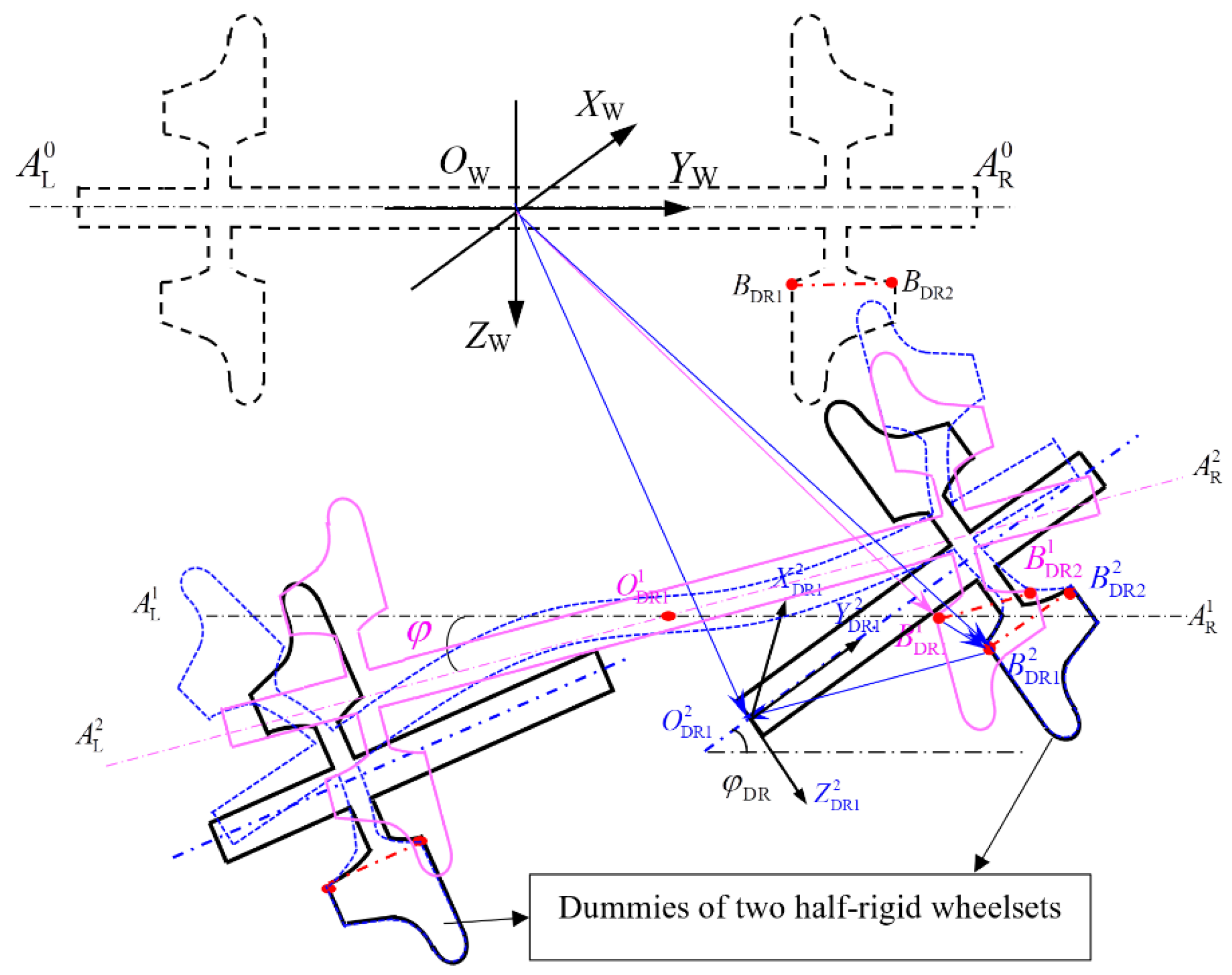
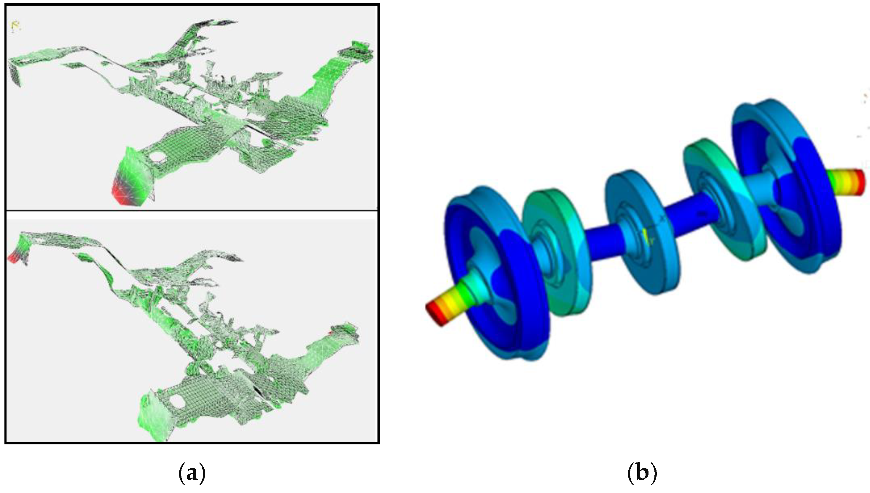
Secondly, the finite element method was used to establish a new model of a flexible wheelset. It considers the higher frequency flexible deformation, such as the umbrella modes and nodal-diameter modes of the wheel, as shown in
Figure 12.
Figure 12a,b indicate the first unsymmetrical umbrella mode and the three nodal-diameter mode, respectively. At this point, the above wheel–rail contact geometry calculation model needs to be further developed in order to consider the influence of the umbrella modes on the wheel–rail rolling contact. In order to simplify the complex geometry calculation of wheel–rail contact, the deformation of the wheel rim was ignored.
It was assumed to be rigid because the cross-section deformation of the rim was very small. In improving the wheel–rail contact geometry calculation model, the dummies of two half-rigid wheelsets were introduced, as shown by
Figure 13 [
55,
56], which was the key to solving the problem. It was assumed that the partial boundaries of the unchanged cross-sections of the wheel rims always coincide with those of the two wheel rims of the two dummies. It can be seen from the wheel profile represented by the blue dotted line in
Figure 13. Thus, the spatial position of the wheel rims of the flexible wheelset was determined by using the two dummies. In
Figure 13, the deformation of the two-point connecting lines on the rim section was very small and it was assumed that they were rigid, as indicated by
,
and
. Reference [
55] gave the detailed description on the complex and tedious modeling, considering the effect of wheel umbrella modes on contact geometry calculation.
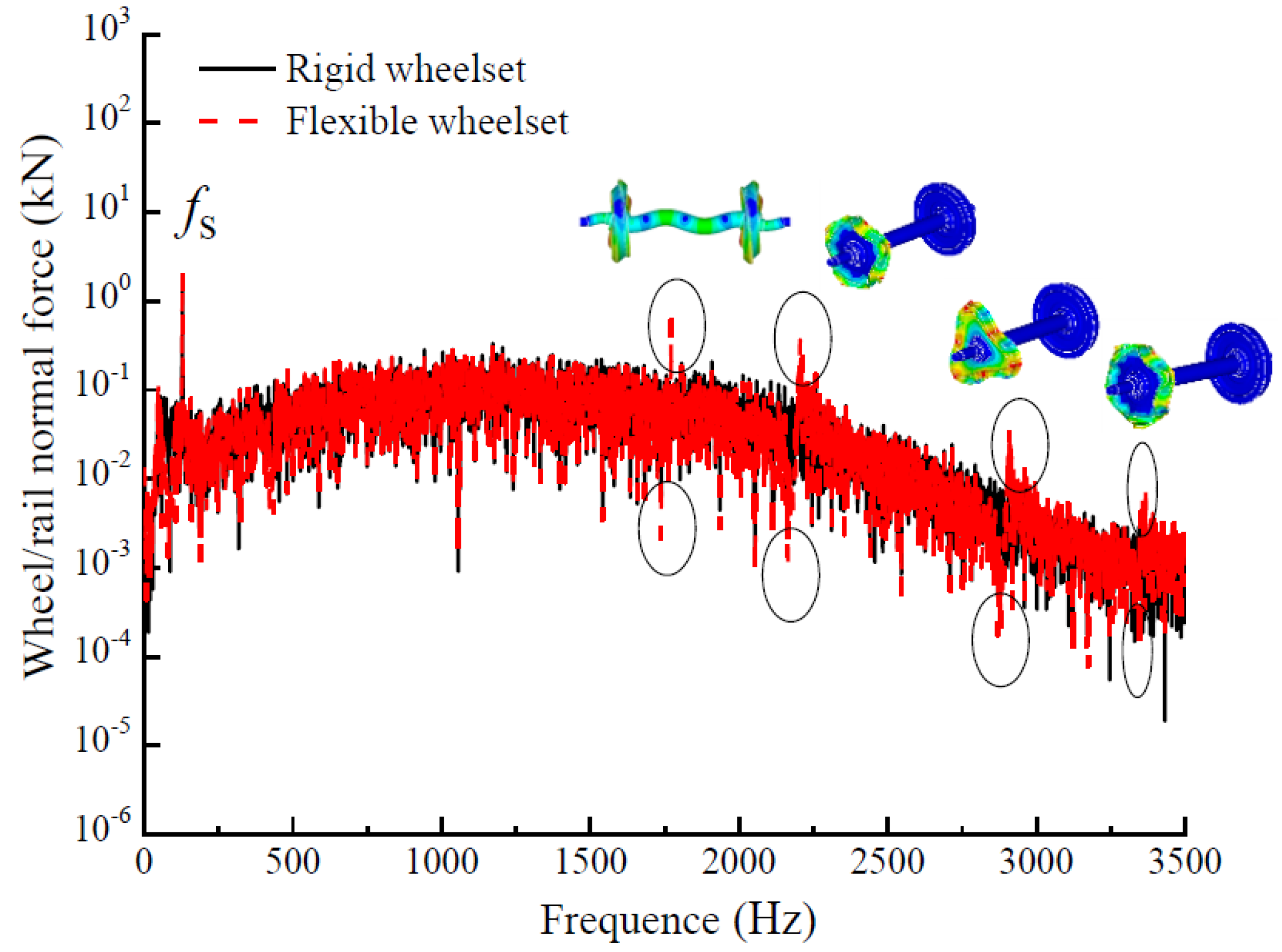
The wheel/rail normal force and wheelset sound pressure level, at 300 km/h and under the random vertical excitation from wheel–rail interface, were calculated by using the vehicle-track coupling dynamical model, considering the effect of the flexible wheelset model and the rigid wheelset, respectively. The frequency range of the random vertical excitation is 0 to 4800 Hz, and the amplitude is 0.02 mm.
Figure 14 indicates the comparison of the wheel/rail normal forces of the two models. The influence of several high-frequency wheelset modes is highlighted, as shown by the peaks in the red curve.
Figure 14 shows the four high-frequency modes of wheelsets, which correspond to the four prominent peaks of the red curve. The peak of
fs is the response to the discrete sleeper support excitation.
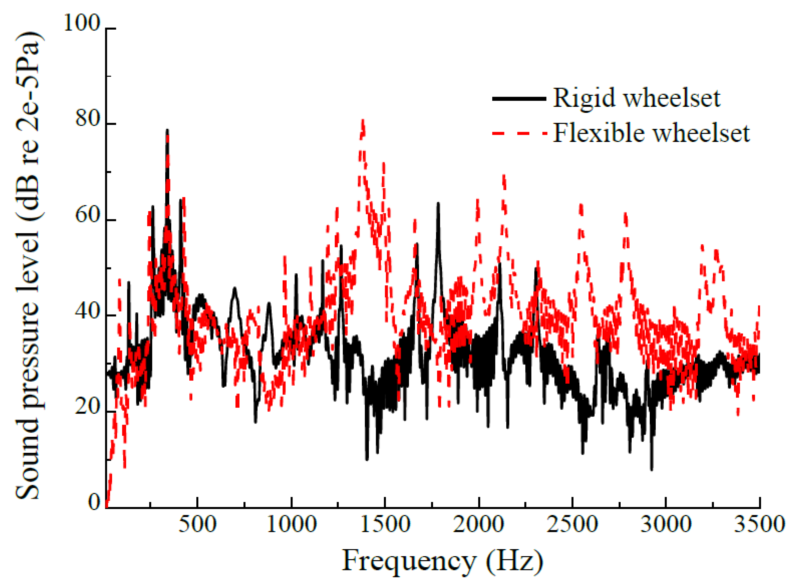
Figure 15 denotes the sound pressure levels of the wheelset in frequency domain by using the two models. It is obvious that the several high-frequency wheelset deformations (or high-frequency modes), shown in
Figure 14, have significant effects on the sound pressure level of the wheelset.
Finally, another new flexible wheelset dynamics model was established to consider the rotation effect of the wheelset. The motion equation of the wheelset, considering the rotation effect, is written as [
55]:
where
and
are, respectively, the modal matrix of the wheelset and its transpose matrix,
is the generalized coordinate column vector of the wheelset,
and
are, respectively, the first and second derivatives of
,
is the column vector matrix of the position of the wheelset at any point at the initial time,
ui and
uj (
i,
j = 1, 2, 3) are the components of
,
is the rolling angular speed of the wheelset along the track,
is the stiffness matrix,
is the generalized force matrix acting on the wheelset,
𝜌 is the wheelset material density,
(
i = 1, 2, 3) is the component of transfer matrix of
and
is a constant matrix of three times three, and in it
E11 =
E33 = 1 and the other elements are zero. An analytical transfer function of wheelset was also given in [
55] and omitted here.
Figure 16 shows the frequency response functions of the flexible wheelset at speeds of 0 and 300 km/h, with and without considering the wheelset’s rotation effect, respectively. Zero speed means that
= 0 in Equation (2), namely the influence of the rotational angular speed of the wheelset is ignored. In
Figure 16, the above figure represents the calculation result of 0–800 Hz, and the bottom figure is the result of 800–2400 Hz.
fband-i (
i = 1, 2, …, 7) indicates the band frequency of the wheelset. Obviously, the rotational angular velocity makes the axle-bending frequencies bifurcate, and with the increase in the bending frequency, the frequency bifurcation of the wheelset-bending vibration tends to decrease.
f(n,m) indicates the frequency of nodal-diameter and pitch-circle modes. The foot symbols, n and m, represent the number of pitch-diameters and pitch-circles, respectively. Obviously, only
f(4,0) is forked.
fum-i (
i = 1, 2, 3) denotes the frequency of the umbrella mode. Wheelset rotation has little effect on the wheel’s umbrella mode frequency.
J. Han et al. discussed the influence of wheelset rotational angular speed on wheel–rail rolling contact behavior and vehicle-track coupling dynamic behavior in the actual high-speed running [
47]. The numerical results show that the influence of the rotational angular speed cannot be clearly identified. Its influence is completely submerged, compared with the influence of geometric eccentricity of wheel, random roughness excitation on wheel–rail contact surfaces, discrete sleeper support, etc. Therefore, in the future in-depth study of high-speed train-track coupling dynamic modeling, whether it is necessary to consider the influence of rotational angular speed of wheelset needs to be further discussed. Because of the influence of rotational angular speed of the flexible wheelset considered in the dynamic modeling of high-speed train-track coupling and the corresponding numerical analysis, the modeling becomes very complicated and the numerical calculation takes a lot of time.
For the actual wheel–rail rolling contact behavior, it cannot be described in details by the current theoretical and experimental methods. The process and mechanism of some problems induced by wheel–rail rolling–sliding contact behavior are still unclear. These problems mainly include wheel–rail adhesion characteristics, short pitch rail corrugation, wheel–rail rolling noise and squeal, interaction between rolling contact fatigue, wear and material properties of wheel and rail, etc. In addition, at present, the model of wheel–rail rolling contact only considers a single wheel and a single rail or half-wheelset and half-track structure with unsprung mass. Its scope of application is limited. Whether the train runs in a straight line or curve, strictly speaking, its dynamic behavior and structure are asymmetric with respect to the central vertical plane of the track. The dynamic behavior (including structure features) of the track, wheelset and vehicle are different along the train’s direction of movement, but they influence each other. The rolling contact behavior of the wheel and rail at different positions of the same train is affected differently. That is to say, the development direction of the wheel–rail rolling contact model has two aspects. One is to consider the influence of a wheel–rail structure’s microscopic factors and material nonlinearity, and the other is to consider the influence of the environmental structural features that constraint wheelsets and rails. Professor Z.L. Li’s research team at Delft University in the Netherlands has been active in this area in recent years. Yang and Li carried out an in-depth analysis on the characteristics of the waves in rail surface, induced by wheel/rail rolling contact [
57]. These wave phenomena were produced by using the explicit finite element model of wheel–rail rolling contact, but they have not attracted much attention from relevant researchers. According to the mechanism of the rolling contact-induced waves, they divided these waves into impact-induced, creepage-induced and perturbation-induced waves. The relation between the generation of perturbation-induced waves and the stick–slip contact mechanism was discussed. The creepage-induced wave was proved to be a Rayleigh wave by analyzing the rail surface nodal motion forming the wave. Their research method and results also confirm that the explicit finite element model of wheel–rail rolling contact can effectively simulate physical rolling contact-induced waves and provide reliable dynamic contact solutions for wheel–rail. The effect of surface crack on the wave was studied by the finite element model, which provides a theoretical basis for crack detection based on the wave characteristics. The research ideas and results are of important reference value for the further study of the mechanisms of longitudinal vibration, short pitch rail corrugation, adhesion characteristics, squeal noise and surface crack of wheel/rail in rolling contact. Z. Yang et al. [
58] systematically discussed the core algorithm of the explicit finite element method and theoretically proved that the explicit finite element method handles nonlinearities in friction, material properties, arbitrary contact geometries and boundary conditions, and fully couples the calculation of frictional rolling contact with the calculation of high-frequency structural dynamics. In order to promote the wide application of this method, detailed steps for establishing a robust wheel–rail dynamic interaction model and obtaining the dynamic contact response were presented. Shen et al. [
59] used two models to analyze the differences in the time and frequency domain of the impact force of the wheel and rail caused by a typical rail squat. The beam model and the continuum model (finite element model) were, respectively, considered in the track modeling of the two models. It was found that the continuum model is more accurate than the beam model by comparing to field observations with the numerical results. In engineering practice, this study can assist engineers in choosing the appropriate assumptions for the wheel, contact and track models when solving wheel–rail impact problems. In the paper [
60], a three-dimensional elasto-plastic finite element model of wheel–rail interaction was established to explore the possibility of martensite phase transition in wheel–rail materials under the influence of thermal energy caused by wheel–rail rolling friction for a critical creepage case.
The paper [
61] puts forward a high-speed wheel–rail transient rolling contact model accounting for the nonlinear displacement-force properties of hanging sleepers. This model was used to analyze the impact contact behavior of wheel–rail caused by the sleeper suspension induced by the irregular rail geometry when the wheel passes over the suspension sleeper at a high speed. At the same time, it was found that the sleeper suspension defect has little effect on the stick–slip state distribution and rolling contact fatigue. The knowledge obtained can provide guidance for assessing the safety condition and maintenance of high-speed ballasted railway tracks.
3. Optimal Matching Design of High-Speed Wheel–Rail
Railway has developed for nearly 200 years, and train running speed has increased from about 10 km/h to 350 km/h. However, the wheel–rail matching problem has not been completely solved so far. The wheel–rail matching problem mainly includes two aspects: geometric size and profile matching, and material matching. Geometric size matching needs to consider the wheelset geometric sizes, track gauge and rail cant. Usually in the design and construction of railway vehicle and its track, these parameters are determined in advance. Then, according to the criteria, which are, respectively, minimum wheel–rail contact stress, minimum wheel–rail wear, excellent passing ability of wheelset on curved track and higher stable running speed on straight track, the profiles of the wheel and rail top are optimized to meet these criteria [
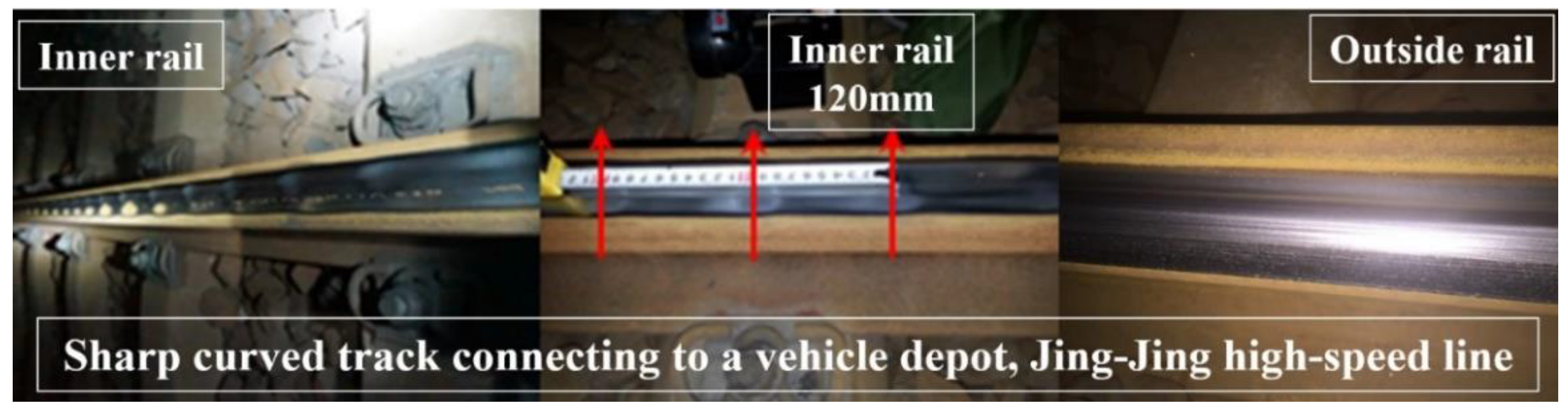
62]. In practice, it is very hard to satisfy these criteria at the same time. Due to the continuous progress of metallurgy and heat treatment technology in the past 20 years, the wear resistance of wheel/rail materials has been greatly enhanced. Therefore, the high-speed rail wear is quite light in the service process, except for rails of sharp curved tracks to train depots [
63]. Moreover, high-speed wheel–rail rolling contact fatigue is not serious, compared with heavy-haul railway, urban railway and the existing railway with mixed passenger and freight transport at speeds less than 120 km/h. One of the most important reasons is that, in the high-speed operation section of high-speed lines, the radii of the curved tracks are large (generally more than 3000 m). When the train passes through the curved tracks of large radii at high speeds, the wheel rim is not easy to contact the inner corner of the high rail, and no serious wear occurs at the corner of the rail. At the same time, the wear of a high-speed train’s wheel rim is also reduced. Therefore, the top profile of the rail in the high-speed operation line section is stable in long-time service. At high speeds, the stability of the train is very sensitive to the change in the wheel tread or the change in the wheelset conicity, due to wear. The optimization design of high-speed wheel profile is priority in the operation and development of high-speed railways in China [
62,
64].
Since people had a basic understanding of the principle of railway wheelset self-guiding motion related to wheel shape in the 19th century, the improvement of wheelset design has never stopped. From the early empirical design method to the widely used computer numerical optimization design method, railway scholars have been looking for wheel profile with the optimal relationship between wheel and rail, so as to fully improve the dynamical performance of locomotive and rolling stock. At present, the design of the wheel tread has achieved fruitful results [
62]. Railway wheel tread used has successfully transferred from the earliest conical tread to the worn tread. However, there are still obvious limitations in the design of the worn tread and its application. So far, the expected functional indicators of the wheelsets, which were put into operation, cannot reach optimal at the same time. The multi-objective optimization technology for wheel–rail interaction is not so mature. Currently, the aim of the wheel tread design mainly improves a single performance parameter, such as the rail profile expansion method [
64] and the normal clearance method of wheel/rail [
65]. They can effectively improve wheel–rail rolling contact performance and reduce wheel–rail wear. However, the wheels designed using these methods contributed little to the improvement of vehicle dynamic behavior because the influence of vehicle suspension parameters was not considered in the design. The inverse design method of equivalent conicity or wheel diameter difference [
66,
67] mainly aimed at improving vehicle dynamics.
In the early years of China’s high-speed railway operation, there were two main types of high-speed trains operating at speeds over 300 km/h. Due to their different suspension parameters, two different conicity wheelsets were used. One with relatively low conicity and relatively thin rims is called Wheel A for convenience. The other with relatively high conicity and relatively thick rims is called Wheel B. Considering the main purpose of applying the two conicity wheels at that time was to pursue the small wheel–rail wear and meet the requirement of better vehicle dynamic behavior only. The following problems appeared soon after the two types of wheels were used. The first common feature of their problems was that the wheelset equivalent conicity increased rapidly with increasing operating mileage, shortly after the new wheels (or just after repairing) in operation. The critical speed decrease in the vehicle hunting (at 1–2 Hz) caused by the conicity increase was faster than the designed or predicted target value. Another common feature was that the trains equipped with new wheels were very stable and comfortable when running on straight tracks at high speeds, and the wheel–rail contact light band (the running surface) was more concentrated. At this stage, the wheel wear was mainly concentrated around the nominal rolling circle, about a hollow wear of 30–40 mm. The depth of more than 50 percent of the wheel hollow wear was in 0.20 mm–0.25 mm [
63]. For subway train wheels, heavy haul train wheels and train wheels on mixed passenger and freight transportation lines, the degree of such hollow wear should be said to be slight and normal, and it did not even get much attention. However, when the train was running at a high speed (above 300 km/h), the running stability of the wheelset was very sensitive to such hollow wear. When the operating mileage was less than 100,000 km, wheelsets and bogies produced lateral sloshing at 7–10 Hz, and the train operation speed had to slow down. That is, such slight hollow wear on the wheels seriously affects the normal operation of high-speed trains. This phenomenon was more serious for the trains with Wheel B than for the trains with Wheel A. When the trains with Wheel A were running on the high-speed straight tracks with rails of minor improper wear at high speeds, the trains often wobbled at low frequencies (1–2 Hz). That time, this was also a problem that puzzled the normal operation of high-speed trains.
According to several years of testing and analyses on the wheel wear state of high-speed trains at operation sites and its influence on vehicle behavior, Cui et al. [
62] proposed a new design method for a high-speed wheel geometric profile, which comprehensively considered common and individual problems in traditional wheel tread designs. The new design idea is indicated by
Figure 17, in which there are two aspects of research and design. The first is the common design, which is usual and the main content of the traditional wheel/rail profile matching design. In the common part design, low contact stress between the wheel and rail is an important index to be pursued. Low contact stress can effectively reduce wheel–rail wear and rolling contact fatigue. A reasonable equivalent conicity of the wheelset can make the wheelset (or vehicle) have a higher critical speed of hunting and a better curve passing ability.
In this part design, it is necessary to consider reasonable wheel/rail clearance. The reasonable clearance ensures that the wheelset conicity does not increase rapidly due to the hollow wear and prevents the wheelset from shaking at 7–10 Hz when running at high speeds. For the high-speed lines built, the track gauge has a 1435 mm+ allowable error. Usually, the clearance between wheel and rail can be changed by modifying the wheel rim thickness only. It effectively reduces the change rate of the equivalent conicity of the original (or new) wheelset (caused by the hollow wear increase). The performance of Wheel B can be improved effectively by reducing the rim thickness of Wheel B.
The individual part design in
Figure 17 is also a key part of the research and design of high-speed wheelsets with outstanding performance. With the help of a large number of field wheel wear test data and their statistics analyses, the profile and geometric dimensions of high-speed train wheels in operation are optimized to improve their performance. The prediction analysis of the optimized wheel performance includes its wheel–rail rolling contact behavior, wear state and potential wear variation trend, influence on the vehicle-track coupling dynamic behavior, internal and complementary factors with vehicle suspension parameters, etc. To accomplish the above tasks, a complete set of theoretical models and corresponding numerical analysis methods are needed. They should include wheel–rail rolling contact model, wheel–rail material wear model, vehicle-track coupling dynamics model and wheel–rail tread matching optimization model. If the performance index of part of the wheel after optimization, predicted in theory, is not up to the standard, further optimization or multiple optimizations should be carried out to achieve the theoretical standard. Then, it is necessary to carry out real vehicle operation test verification after so many cycles (verification to optimization and improvement, and then verification) to achieve the most desired goal.
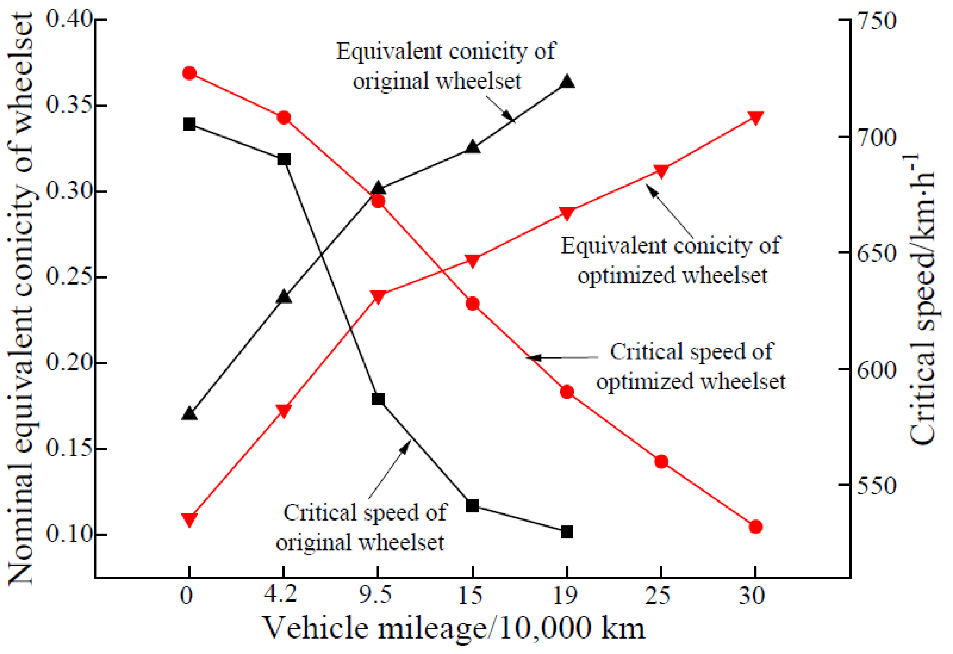
According to the design scheme shown in
Figure 17, a new type of high-speed wheel tread was designed.
Figure 18 indicates the equivalent conicities of the new designed high-speed wheel and Wheel B, and their hunting critical speeds with the increase in operating mileage. Obviously, the re-profiling interval of the new designed high-speed wheel increases by 30%. At the same time, in the range of the lateral wheelset deviation of less than 8 mm, the wheel/rail contact pressure of the new high-speed wheel is lower than that of Wheel B. In the operating speed range from 200 km/h to 400 km/h, the average wear work index of the new designed wheel is greatly reduced and the change in its wear work index is very small [
62]. The design concept in
Figure 17 successfully supports wheel MB10 design of a FUXIN high-speed train [
68]. At present, the design of a subway train wheel profile is also on trial following
Figure 17.
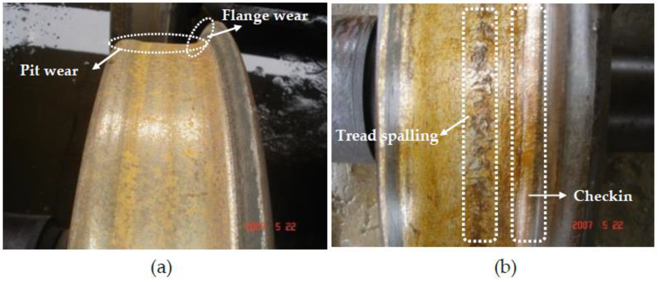
Optimal matching of wheel and rail materials is the other key problem. It includes two aspects of research content. One is the suitable hardness ratio of wheel material to rail material, and the other is the proper hardness and toughness of wheel/rail material itself. Optimal matching of wheel and rail materials can effectively prevent wheel/rail wear and rolling contact fatigue. Wheel/rail wear and fatigue crack are the main damage states in service.
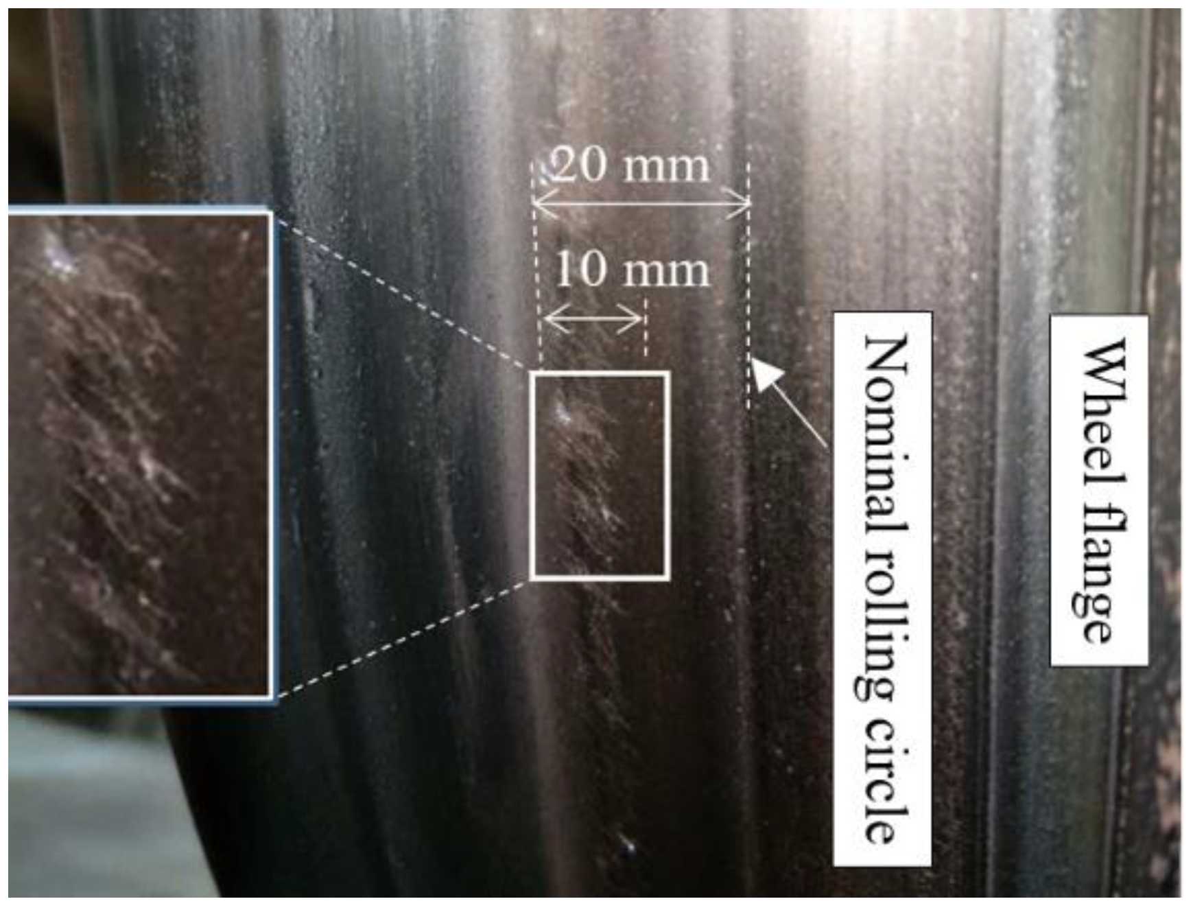
Figure 19a indicates the serious pit wear (called hollow wear) on the lateral tread of the wheel (working face) and wheel flange wear. This kind of wear state causes the critical speed of stable operation of the vehicle to decrease greatly, and its performance through the curved tracks becomes poor.
Figure 19b denotes wheel tread spalling and flange root checking. They will lead to high-frequency contact vibration and noise of the wheel and rail and seriously cause wheel breakup, lead to derailment accidents.
What is the suitable hardness ratio of wheel material to rail material? The correct answer is related to the balanced development of wheel/rail wear and their mutual adaptation, which ensures the excellent dynamic performance of trains in long operation processes. It is also related to the low operating cost. For high-speed rail in Japan, the hardness ratio of wheel–rail materials is about 1.2. In Europe, the hardness ratio is 0.94–1.07, and 0.94–0.98 for China’s high-speed railway [
69]. The selection and practical use of these ratios are basically based on experience, without strict engineering scientific test verification and theoretical analysis data demonstration. The optimal value of the ratio has not yet been found. Its choice is also controversial in the rail industry. At present, there are no good methods nor ideas to find its best value.
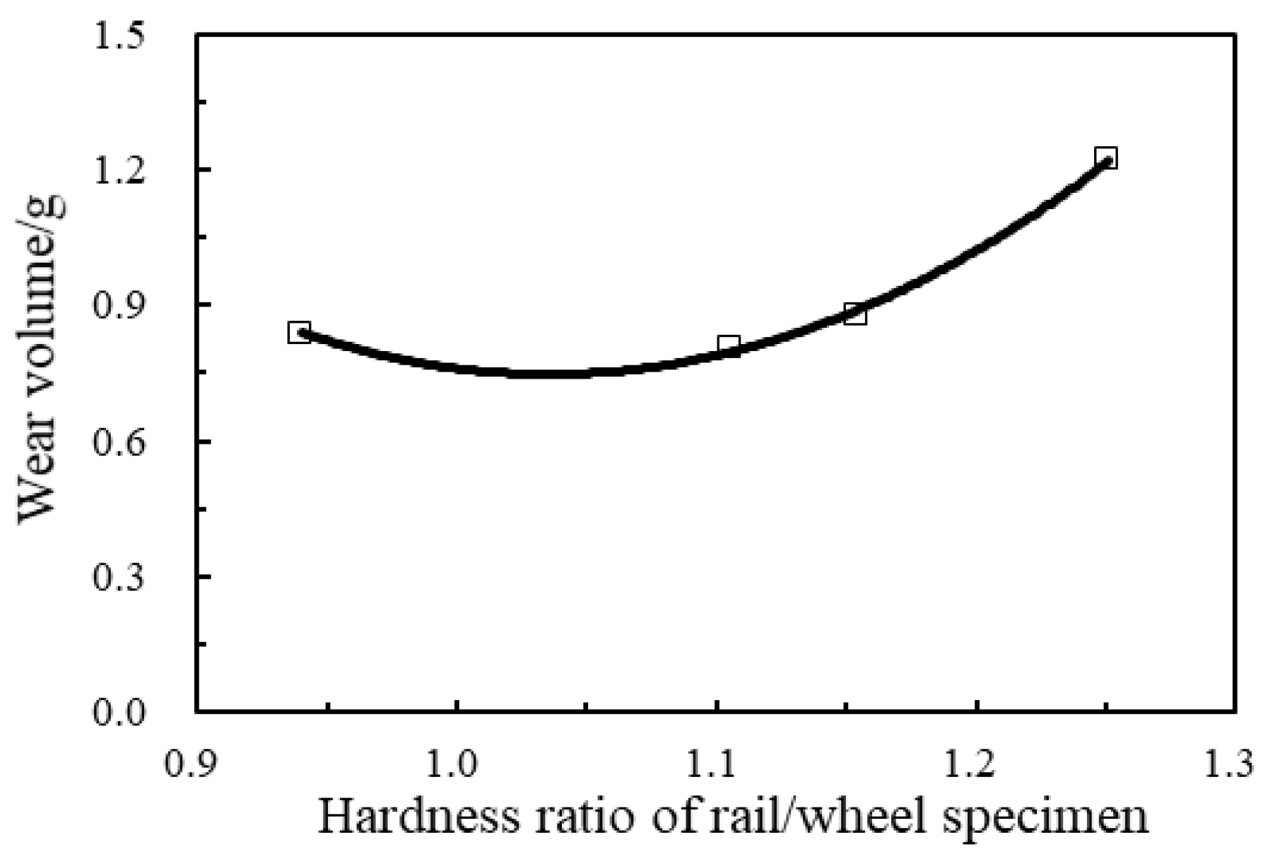
There is a traditional view or experience in railway operation and maintenance. That is, the repair and replacement of wheels are much more convenient and cheaper than rails. It is generally recommended to use wheel material hardness, which is slightly lower than that of rail material. Researchers from Southwest Jiaotong University used the small-scaled wheel–rail test device to test the wear of high-speed wheel–rail materials under rolling and sliding states.
Figure 20 shows the change in total wear amount of wheel/rail specimens with different material hardness [
70]. A disk-simulating wheel was considered as a driving disk in the test device and the other disk-simulating rail was a driven disk. It was found that the total wear amount of the wheel/rail materials was the lowest when the hardness ratio of the rail/wheel specimens was about 1.05. The curve in
Figure 20 was fitted into a unary quadratic polynomial. This interesting phenomenon suggests whether different hardness should be applied to locomotive wheel materials and trailer wheels. If so, this obviously increases the cost of wheel manufacturing and operation maintenance.
Figure 21 shows a schematic diagram of working hardening and frictional wear of materials of wheel–rail contact surface. The vertical axis on the right represents the hardness of materials of the wheel–rail contact surface, the horizontal axis
NR represents the number of wheel/rail rolling contact, the red curve
Ym(
NR) represents the nominal hardness function of the contact surface materials, the blue curve
Ys(
NR) represents the actual hardness function of the materials,
Ys(
NR) is lower than
Ym(
NR) because the wheel/rail contact surface materials are constantly worn away,
Y0(HB) is the initial hardness of wheel/rail surface materials,
hW (
NR) is the wear depth of the contact surface and
K in the Figure represents the intersection point of the wear depth and the actual hardened layer depth. When the wear depth is equal to the hardened layer depth, if the wheel/rail continue to roll slip wear, the wear will increase rapidly.
There are two more important factors to consider in wheel/rail material selection. The first consideration is that, for operating on the same line, the number of rolling extrusions of wheel material is different from the number of rolling extrusions of rail surface material, then the wheel wear and the rail wear are different every day. If the influence of the difference in the wheel–rail material properties on the wear of the wheel and rail is not considered, the ratio of the average wear of each wheel to the average wear of the rail in operation on the same line is expressed by formula (3). If calculated according to formula (3), the daily wear of the wheel on a certain line is usually dozens of times that of the rail. Considering the factors discussed above, determining the hardness ratio of wheel material to rail material is really a difficult problem to study.
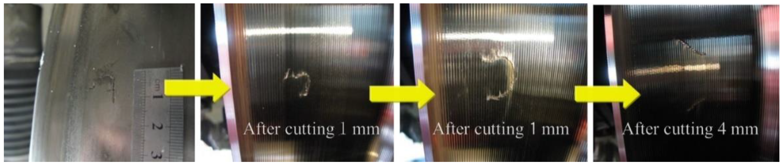
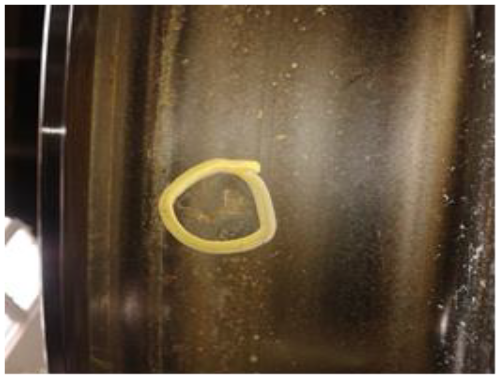
The second consideration in choosing wheel–rail materials is the appropriate hardness and the appropriate toughness of the material itself. The high hardness and high toughness of wheel/rail materials themselves can resist effectively wear and rolling contact fatigue. However, in general, the requirement for both high hardness and high toughness of metallic materials is difficult to be satisfied. Improving the hardness of the material, that is, increasing the yield strength of the material, can effectively improve the wear resistance of wheel–rail contact surface, but for the high hardness of the material, its toughness is difficult to meet the requirement of crack resistance development. Therefore, to improve the performance of wheel/rail materials, it needs to improve its hardness and toughness at the same time, that is, in choosing wheel and rail materials, their hardness and toughness need to be guaranteed at the same time.
At present, the wheel/rail material selection can only be made by means of extensive practical experience and reference to test results of laboratory test equipment. The basic idea is to carry out the test simulating a wheel rolling over a rail with a pair of rollers, namely disc to disc. During the test, test specimen materials with different toughness and hardness are changed, and the sliding and normal contact force of two discs are set close to the actual situation of the wheel–rail in service, and rolling–sliding test is carried out under different mileage conditions. The test results should show the following three situations: (1) if the crack and exfoliation on the contact surface of the specimen are serious, the hardness of the material is too high to be used. (2) If there is no crack and the wear is too severe, the material is too soft or has too high of toughness. The hardness is not enough and should not be used. (3) If the crack position is constantly changed with the increase in the test mileage due to wear, and also the length and depth of the cracks are not large, the toughness and hardness of the material are appropriate or balanced. This kind of material basically meets the requirement and may be recommended to use. So far, no research results have been published in this respect. It is obvious that there are the following deficiencies in the selection of metal materials for the wheel and rail by the above test method. If the material properties of the wheel and rail are not different, their wear amount is not different in every rolling contact. The hardness change in the wheel and the rail in actual operation is different from that of the test specimens. The test environment is also different from the fields, including the effect of the attachments. Interaction mechanism of fatigue crack and wear on wheel–rail rolling contact surface reproduced by the test process is not quite the same as the situation in the field. At present, the best match of hardness and toughness of wheel/rail materials has not been found. Only efforts can be made to improve the hardness and toughness of wheel/rail materials at present.
4. Adhesion Theory and Mechanism of High-Speed Wheel–Rail in Rolling Contact
Wheel–rail adhesion is an important factor affecting the safety and efficiency of train operation. Especially for high-speed trains in operation, the requirements for high-acceleration and high-deceleration capacities are becoming increasingly high, and the traction and braking forces between the wheel and rail rely on the property and level of the adhesion in the wheel/rail contact patch. Therefore, it is particularly important to explore the key factors affecting the property and level of wheel/rail adhesion in rolling contact at high speeds. The ratio of the longitudinal tangential force to the normal pressure between the wheel and rail is defined as the adhesion coefficient by the railway industry. It is taken as an important parameter to measure wheel–rail adhesion characteristics.
The adhesion coefficient is mainly related to the friction caused by wheel–rail contact surfaces. It is affected by wheel–rail material properties, contact surface states, contact surface attachments, vehicle operating conditions, environmental conditions and so on. In the past, research on the influence of these factors on wheel–rail adhesion characteristics mainly relies on experimental methods. China’s large-scale high-speed railway operation and the statistical analysis of field test data shows that the adhesion characteristics at less than 350 km/h under dry conditions can satisfy the traction and braking of the train well. The real impact on the adhesion is the contact surface state and the attachments on the contact patch. These attachments include rain water, dew, water pollution caused by fog, oil pollution caused by oil leakage from vehicles and engineering equipment, fallen leaves, contact surface rust and oxidized metal abrasive particles. In recent decades, scholars have focused on the analysis on the influence of the attachments on the adhesion characteristics. Although some progress has been made, the problem of wheel/rail adhesion cannot be solved satisfactorily. Ohyama T. and his collaborators made outstanding achievements in experimental research. They systematically studied the influence of surface state and operating parameters on the adhesion characteristics by means of a small-scale double-disk rolling test device [
71,
72]. Zhang W. et al., Gallardo-Hernandez, Lewis, Wang, Arias-Cuevas, Li et al. and Olofsson et al. studied the wheel–rail adhesion characteristics under oil lubrication or water lubrication by using full-scale or reduced-scale rolling devices, respectively [
73,
74,
75,
76,
77,
78,
79]. The adhesion coefficient distribution in the speed range of 30–270 km/h was obtained through the tests under the condition of water spraying on the track of Japan Shinkansen [
18,
80], and the relation function between the adhesion coefficient and the operating speed was fitted by using the test data.
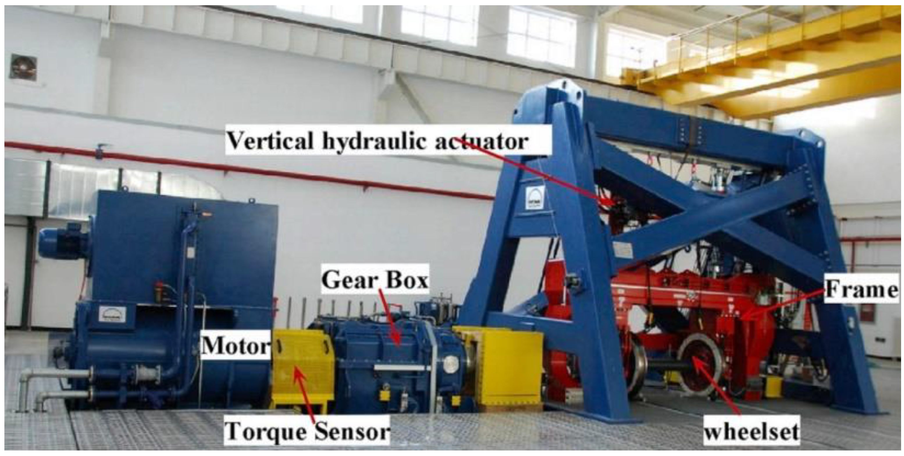
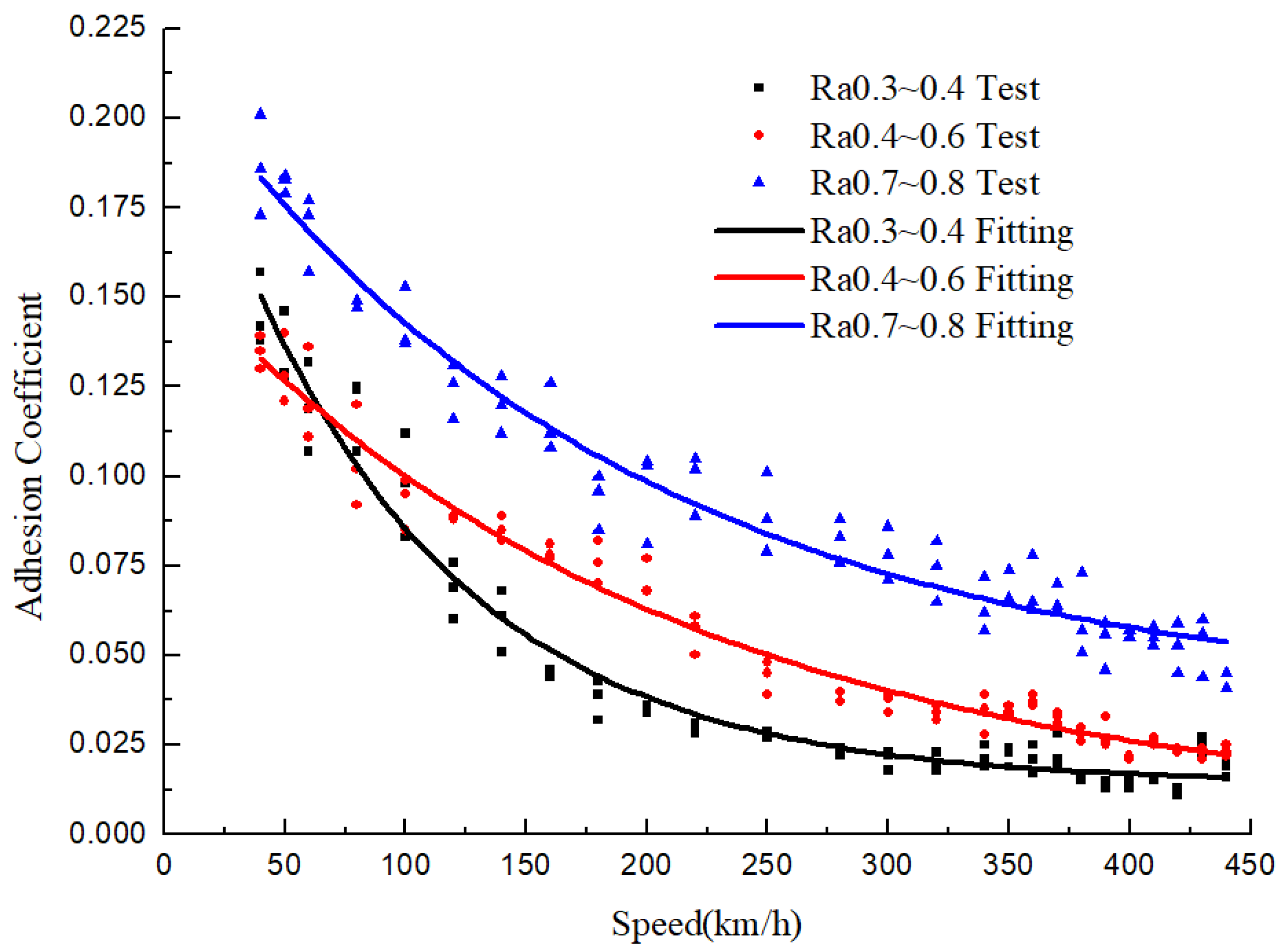
Chang et al. used 1:1 high-speed wheel–rail test device (as shown in
Figure 22) to reproduce the characteristics of the wheel–rail adhesion coefficient. In the test, they considered the influence of different wheel–rail interface roughness levels, axle loads, wheel–rail interface water volumes, wheel–rail creepage levels and ambient temperatures on the adhesion characteristics. The test speed reached 440 km/h.
Figure 23 shows the test results. It indicates the variation in the adhesion coefficient with the operation speed, different roughness levels and water mediums [
81].
In the test of
Figure 23, the axle load is 17 tons, the wheel–rail creepage is set at 2% and the amount of water sprayed on the wheel–rail contact surface is 300 mL/m. In
Figure 23, Ra denotes the roughness level, the symbols ▲, ● and ■ represent the test results at different roughness levels and solid lines with different colors represent their fitting results. For water pollution and the three roughness levels, as the test speed increases, the wheel–rail adhesion coefficient decreases rapidly. The decreased rate of the adhesion coefficient is almost the same for the two higher roughness levels. For the lowest level roughness (the contact surface is relatively smooth), the drop rate is the largest in the range of 50–200 km/h. The reason is that for the lower roughness level of the contact surfaces (or relative smooth surfaces), the water mucous membrane on the wheel–rail interface is easier to form with the rolling speed increase. In the situation, the solid contact ratio between wheel–rail interface decreases rapidly, and the contribution of solid friction to the tangent force decreases rapidly. This leads to the rapid decrease in the wheel–rail adhesion coefficient. These results have an important value for evaluating wheel–rail adhesion level, safe operation and rational adhesion utilization of higher-speed trains in service.
Due to the complexity of wheel–rail in rolling contact and many factors affecting the adhesion coefficient, the establishment of a physical model and numerical method is still a challenging problem. This problem is related to the research on the influence of attachments between wheel and rail, micro-roughness of the contact surfaces and material nonlinearity. Therefore, the research progress in this area is particularly lagging behind. At present, elasto-hydro-dynamic lubrication theory and microscopic solid contact theory are widely used to analyze the adhesion characteristics.
Figure 24 indicates the physical model of wheel–rail adhesion taking into account such factors as the elastic fluid between wheel and rail, wheel/rail elastoplastic microscopic roughness, wheel rolling speed, etc.
Figure 24a indicates that a power wheel rolls on a rail at speed
v with drive torque
T and vertical load P. So, the adhesion force between the wheel and the rail is
F.
Figure 24b,c show the geometric amplification of the wheel–rail contact area. They describe the microscopic roughness amplitude (
δ1,
δ2) of the contact surfaces and the fluid between the wheel–rail interface, respectively.
Figure 24d shows three texture states of rough surface (
γ < 1, =1 and >1).
γ < 1, =1 and >1 represents the distribution state of roughness texture along longitudinal, longitudinal and transverse and lateral directions, respectively. This wheel–rail contact state seriously affects the wheel–rail adhesion coefficient or wheel–rail adhesion force
F.
According to
Figure 24, Ohyama T. first introduced the elasto-hydro-dynamic lubrication theory into the study of wheel–rail adhesion and theoretically studied the adhesive characteristics of the attachments on the rough surfaces of wheel–rail [
82]. Chen H et al. found that wheel–rail surface roughness and temperature have a great influence on the adhesion coefficient by using a simplified model and compared the calculated results with the measured results on Japanese Shinkansen, and the results were in good agreement [
83]. This model is a mixed lubrication model established on the basis of the Grubin theory.
Wu B et al. developed a two-dimensional numerical model. The numerical method adopted “the Multi-grid Method” with better stability in the numerical iteration. Using it obtained the wheel–rail adhesion characteristics in a water medium and oil medium at higher speeds (up to 500 km/h). The influence of roughness parameters, axle load and operation speed on the adhesion coefficient was analyzed in detail, and the variation characteristics were explained from the quantitative point of view. The numerical results are in good agreement with the experimental results. In addition, they also analyzed the influence of the different physical properties of water and oil on the adhesion characteristics. They found that the adhesion coefficient decreased faster than that of water in the presence of oil pollution on wheel–rail surface, and explained the causes from the numerical point of view [
84,
85,
86]. Chen H et al. developed a three-dimensional calculation model using the mixed lubrication theory to numerically analyze the adhesion characteristics in a water medium. It was found that speed, water temperature and surface roughness had great influence on the adhesion coefficient. In the calculation, they considered the effect of the size parameters of a small-scale testing machine. Finding the numerical solution needs to avoid the small film thickness ratio and the numerical stability problem caused by the extreme working conditions (film thickness is negative), which is related to wheel–rail contact. In addition, the simulation condition of the point contact is different from the actual wheel–rail elliptic contact patch [
87]. The obtained result has theoretical significance, but the prediction of actual wheel–rail adhesion needs careful consideration. To this end, Wu B et al. extended their two-dimensional model to a three-dimensional model [
88]. The geometric dimensions and actual normal load at the wheel–rail contact point of a CRH2 high-speed train were considered in modeling and analyzing. The variation in the adhesion coefficients with operation speed, wheel/rail contact surface roughness, axle load and other factors were obtained. The calculated results are in good agreement with the experimental results.
The numerical models discussed above are all aimed at the existence of a single medium between wheel and rail, and there may be more than two or more mixed media on the actual wheel–rail contact surfaces. Therefore, Wu B et al. established a wheel–rail adhesion model with a water and oil mixture [
88,
89]. They believed that the difference between water and oil is mainly in viscosity, and considered that the wheel–rail surface roughness level and the thickness of water–oil film were basically in the same order of magnitude. It was assumed that water and oil are stored in segments in the surface bulge between the wheel and rail, and a unified equation was used to solve the solution of the whole contact area. The adhesion coefficient they obtained is somewhere between the results when considering the effects of water and oil alone. It is in good agreement with the current experimental results. However, the longitudinal interaction of the water–oil medium is neglected in their study. In practice, large longitudinal slippage between wheel and rail is inevitable during traction and braking, which can lead to an increase in temperature and influence the adhesion coefficient. Therefore, their theoretical model needs further improvement.
Through experiments and numerical analysis, Chen H. found that the influence of water temperature on the wheel–rail adhesion coefficient could not be ignored [
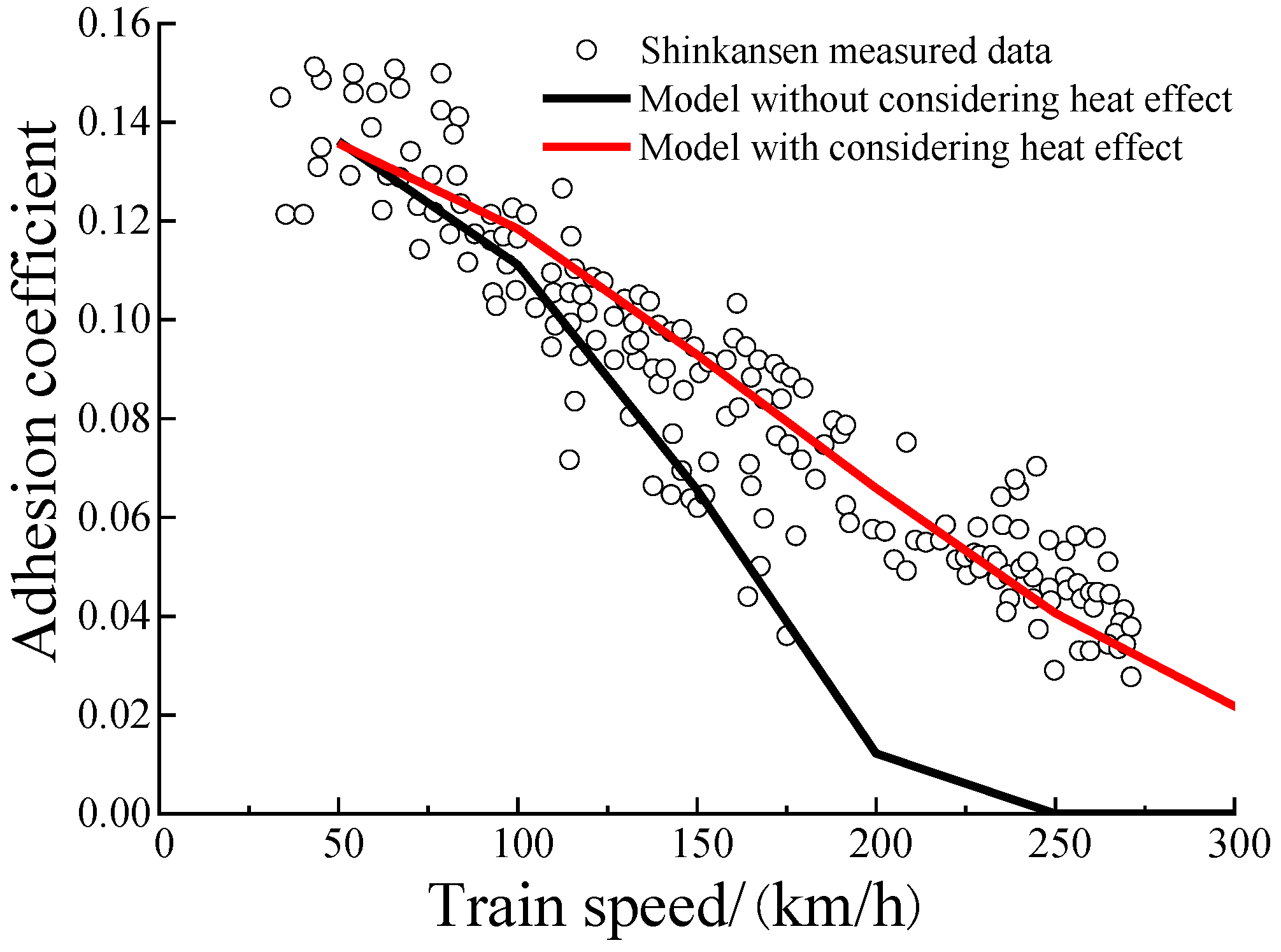
90]. However, there is, so far, no numerical model which can take temperature-rise, rheology, micro-roughness and elastoplastic deformation into account at the same time. To simplify the model, on the basis of Chen’s simplified model, Wu B et al. [
89] considered the friction temperature-rise between solid rough peaks in the inlet region of the contact patch and the elastoplastic contact between microscopic rough peaks proposed by Zhao Y et al. [
91] at the same time. The variation in the adhesion coefficient with and without the influence of heat was calculated. The numerical result obtained is shown in
Figure 25. Obviously, the numerical result considering the thermal effect is closer to the actual experimental result. Meanwhile, the distribution of the wheel–rail adhesion coefficient under the influence of multi-factor coupling was investigated, as shown in
Figure 26. It can be found that the roughness level of wheel/rail contact surface and the operation speed have a great influence on the adhesion coefficient, which is similar to the characteristics shown in
Figure 23.
Recently, studies on the characteristics and mechanism of high-speed wheel–rail adhesion have considered the vehicle-rail coupling system and the problem of adhesion-induced damage. Based on the high-speed wheel/rail adhesion experiment, Wu et al. [
92] generalized the application of the functional friction coefficient parameters of Polach in the water medium suitable for high-speed conditions, modified the simplified FASTSIM theory, and conducted the numerical simulation of high-speed train traction with large sliding. The attrition and fatigue characteristics of wheel/rail under large traction sliding were investigated preliminarily. Combined with the vehicle/track coupling dynamic model and the deterministic mixed lubrication model, Wu et al. [
93] established a new high-speed wheel–rail adhesion dynamic model of the high-speed train passing over a curved track in the presence of a water medium. The model also considered the effects of starvation oil and measured three-place roughness on wheel–rail adhesion. The transient adhesion characteristics at different speeds were obtained.
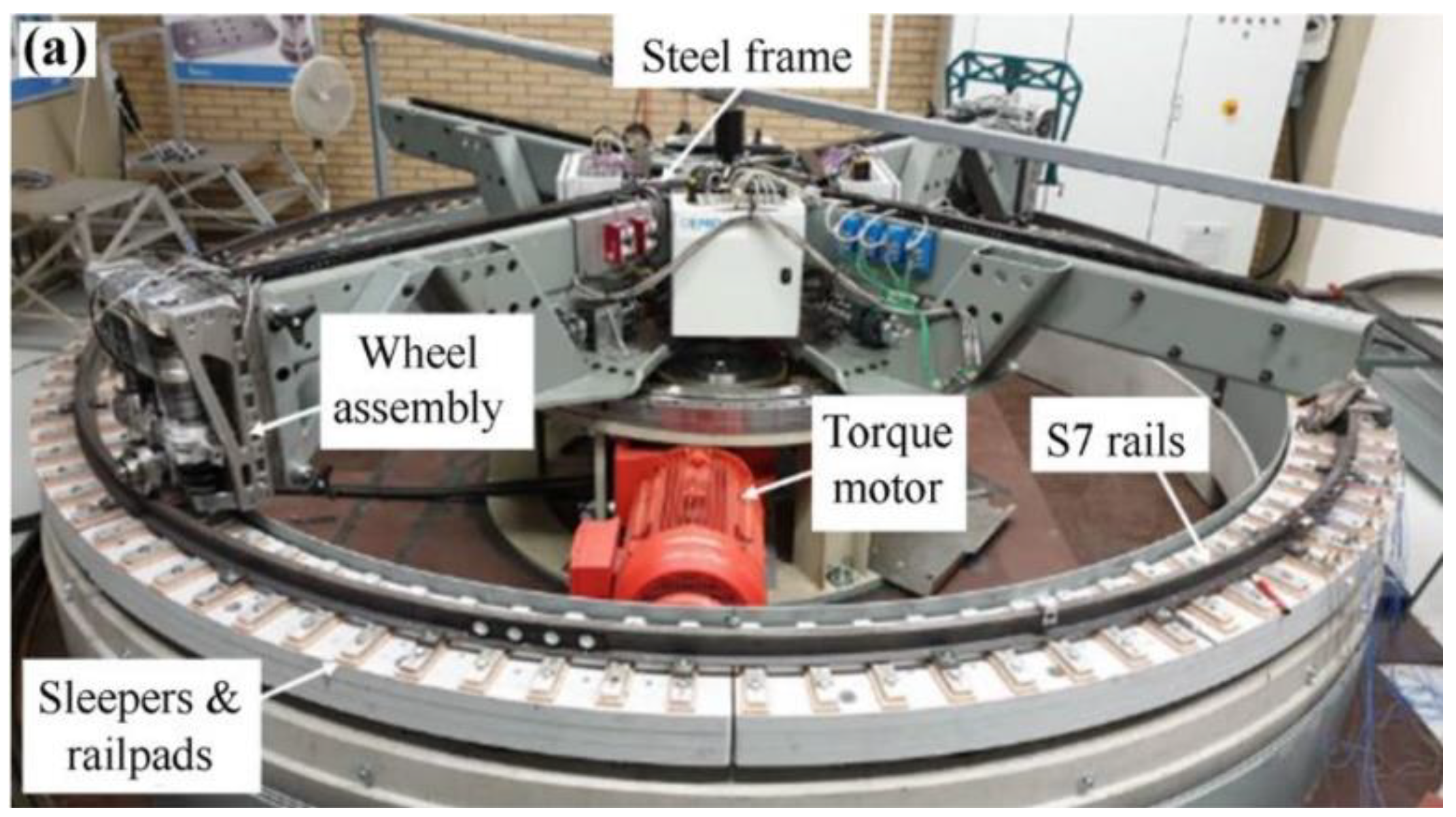
The application of friction modifiers has been recognized as a promising emerging tool in railway engineering to mitigate wheel–rail interface deterioration, energy consumption, vibration and noise by modifying friction to the level which is required to increase the wheel/rail adhesion coefficient under consideration of adverse friction conditions. Yang et al. [
94] experimentally investigated the effects of two types of top-of-rail friction modifiers and their application dosages on wheel–rail dynamic interactions with a range of angles of wheelset attack using an innovative well-controlled V-track test rig, as shown in
Figure 27. The research results promote the technical performance improvement and application of friction modifiers and improve the dynamic action of wheel and rail.
Although some wheel/rail adhesion mechanisms have been clarified by using experimental and numerical methods, the actual wheel–rail contact behavior is very complex and influenced by many factors. The following problems still need to be solved in experimental and numerical simulation aspects: (1) the numerical convergence in the presence of a water medium with a small film thickness ratio; (2) a more accurate numerical model considering the influence of multi-factor coupling (temperature, micro-roughness, elastoplastic contact with liquid, rheological sand, leaves and other pollutants) on the adhesion coefficient; (3) numerical simulation of real geometrical characteristics of micro-roughness; (4) in the process of high-speed wheel–rail adhesion test, the influence of the change in the real geometric characteristics of micro-roughness on the adhesion coefficient due to rolling and wear of wheel–rail; (5) experimental and numerical modeling of new viscosifiers between wheel and rail at higher speeds. Only in this way can we estimate the change law of wheel–rail adhesion more effectively and accurately and provide a theoretical basis for the measures to improve the adhesion coefficient of high-speed wheel/rail system, so as to ensure the safety of high-speed train operation.
