Experimental and Numerical Study on Mixed Lubrication Performance of Journal Bearing Considering Misalignment and Thermal Effect


School of Mechanical and Power Engineering, Zhengzhou University, Zhengzhou 450001, China
*
Author to whom correspondence should be addressed.
Lubricants 2022, 10(10), 262; https://doi.org/10.3390/lubricants10100262
Submission received: 28 September 2022
/
Revised: 10 October 2022
/
Accepted: 11 October 2022
/
Published: 16 October 2022
Abstract
:The shaft misalignment under mixed lubrication is an important factor affecting the running performance of the bearing, which can occur under heavy load and unsatisfactory assembly. This paper presents a misaligned journal mixed lubrication model coupling for the asperity contact effect, elastic deformation, viscosity–temperature, and viscosity–pressure effect. The finite difference method was employed to calculate the model, and an experimental apparatus designed in this paper was used to test the friction and temperature characteristics of the specimens. The results show that the pressure field, film thickness, and elastic deformation of the bearing conformed to asymmetric distribution along the axial direction under misalignment conditions and there was a notable end side effect. In addition, the frictional force and side leakage flow were evidently enhanced with the increase in the inclination angle in a certain range. The experimental results showed that there was a visible wear phenomenon on the end sides of the bush and shaft. The research results are beneficial for understanding the mixed lubrication mechanism of misaligned journal bearing.
1. Introduction
The demand for equipment diversification has led to an increase in the extreme operating conditions of bearing. The film thickness and roughness have the same order of magnitude under start-up or heavy load, resulting in the hydrodynamic lubrication transforming into mixed lubrication. Furthermore, due to the shaft deformation, heavy load, manufacturing or assembly error of the shaft-bearing system, misalignment becomes an inevitable fault and generates influences on the bearing lubrication performance [1,2,3]. In the mixed lubrication state, the misaligned journal bearing shows a complex operation state. Therefore, it is necessary to carry out in-depth research on the mixed lubrication mechanism of misaligned journal bearing.
In recent years, there have been some studies concentrating on mixed lubrication performance analysis [4,5,6,7,8] and journal misalignment analysis [9,10,11]. Cui et al. [12] investigated the mixed lubrication transient performances of the bearing during startup. The authors concluded that the transient characteristics of the bearing are greatly influenced by surface roughness. Guo et al. [13] studied the surface texture on the wear characteristics of diesel engines. Zapletal et al. [14] performed an experimental analysis of friction and film thickness during the lubrication transition from elastohydrodynamic lubrication to mixed lubrication. Prölß et al. [15] studied the mixed lubrication performances during the transient run-up procedures of the bearing by theoretical and experimental methods. In their study, the run-up time had a greater influence on the frictional coefficient and there was an opposite difference between the mixed lubrication region and hydrodynamic region. Over time, Lv et al. [16] explored the influence of local turbulence on bearing lubrication by separating the HD lubrication and MHD lubrication regions. In this study, the friction coefficient was influenced significantly by local turbulence. More recently, the effect of surface texture on mixed lubrication performances has been investigated [17,18]. In their studies, the texture shape had a notable influence on the tribological performances of the bearing. Xiang et al. [19] proposed a transient tribo-dynamic model for mixed lubrication analysis of a slide bearing during start-up. The authors concluded that a short acceleration time achieved a maximum temperature increase, although it reduced the asperity contact, and the radial clearance and shell thickness had evident effects on the bearing performances. Xie and Zhu [20] investigated different lubrication conditions of water-lubricated bearings by using the coupled models of micro-scale asperity contact. In their studies, the surface roughness, clearance, etc. parameters had significant effects on the lubrication condition transformation. The journal misalignment was not considered in the studies above. However, because of the asymmetric load, manufacturing, and assembly error of journal bearing, etc., the journal would become misaligned and have an inevitable effect on the bearing lubrication performances.
Sun et al. [21,22] studied the lubrication performances of a misaligned journal considering the surface roughness and elastic deformation. Subsequently, Jang and Khonsari [23] systematically reviewed the influence of misalignment on the bearing performance, and they observed that the misalignment could generate wear, vibration, and even equipment failure. Zhang et al. [24] explored the load capacity of a misaligned water-lubricated bearing by a number of CFD analyses. The authors found that the inclination angle, relative clearance, length to diameter ratio, and rotational speed had effects on the load capacity. Lv et al. [10] proposed an approach to analyze the equivalent supporting position and load capacity of the journal bearing with misalignment. Over time, other factors have been considered in bearing lubrication analysis with journal misalignment. Li et al. [1] analyzed the lubrication performances of a misaligned journal bearing, accounting for the thermal effect and axial movement of the shaft. In their numerical study, the effects of the axial movement of the shaft on the bearing performance was affected by the eccentricity, rotational speed, surface roughness, and thermal effect. Das and Guha [25] investigated the effect of turbulence on the characteristic of misaligned journal bearing. The authors found that the load capacity increased after considering the effect of turbulence. Manser et al. [26] studied the effect of surface texture on the performance of hydrodynamic journal bearing with journal misalignment. They found that the texture location and geometry shape were important parameters in bearing characteristics, and the square shape texture improved the misaligned bearing lubrication characteristics most significantly. Zhang et al. [27] performed a thermoelastohydrodynamic analysis of journal bearing that considered the surface texture and misalignment. In their study, the surface texture could improve the lubrication performances of the misaligned journal bearing, and the oil temperature, oil film pressure, and load capacity increased after considering journal misalignment. Xiang et al. [28] analyzed the transient lubrication performances of a misaligned micro-grooved bearing. In their model, the axial movement of the journal was also considered. Abdou and Saber [11] studied the stability of misaligned journal bearing and concluded that the bearing stability critical value increased with the increase in the misalignment degree in a certain direction angle. Zheng et al. [29] introduced the couple stress effect in the critical film thickness region, and analyzed the lubrication performances of a misaligned journal bearing. The research above prove that journal misalignment generates significant effects on the lubrication performances of the bearing.
In the meantime, the mixed lubrication analysis considering journal misalignment has been developed. Lv et al. [4] developed a mixed lubrication model considering both the wall slip and misaligned journal of metallic stern bearings. The authors found that the minimum nominal film thickness decreased, but the friction coefficient increased after considering the wall slip and journal misalignment. Subsequently, the effects of turbulence on the mixed lubrication properties of the misaligned journal bearing were investigated by Lv et al. [30]. Jang and Khonsari [31] studied the effects of wear on the characteristics of engine bearings considering journal misalignment. In their numerical study, the hydrodynamic pressure was much greater than the asperity contact pressure, and the wear was determined by the contact pressure, roughness, and oil film thickness. The studies above on the analysis of the mixed lubrication properties of misaligned journal bearing assumed that the lubricant viscosity was constant. However, the viscous dissipation and asperity contact in the mixed lubrication condition would generate more heat, resulting in the change in the lubricant viscosity. The change in viscosity under mixed lubrication will have a significant impact on the running performance of the bearing. Therefore, the change in viscosity should not be ignored, especially under the mixed lubrication condition with journal misalignment.
In this paper, a mixed themoelastohydrodynamic lubrication model considering journal misalignment was established, which couples with the asperity contact, elastic deformation, viscosity–pressure, and viscosity–temperature effect. The hydrodynamic pressure, contact pressure, temperature field, and bearing performance parameters were computed and compared between the aligned condition and misaligned condition. In addition, a friction characteristic experiment was carried out to test the improved friction and wear machine. This paper provides a better understanding of the mixed lubrication mechanism with journal misalignment.
2. Modeling
2.1. Misaligned Journal Geometry Model
As shown in Figure 1, the oil film thickness will change in the axial direction when considering journal misalignment. The journal center and bearing center distance is referred to as the eccentricity, and the angle between the line of eccentricity and the vertical direction is called the attitude angle. Therefore, the eccentricity and attitude angle need to be modified, and they are different in each axial section. The eccentricity and attitude angle can be written as:
where z is the axial coordinate representing the axial section position; α is the angle between the line connecting the centers of the front and rear section of the journal and the centerline of bearing. β corresponds to the angle between the projection line connecting the front and rear end face centers and the eccentricity direction OO1. α and β are also known as the degrees of misalignment at the axial direction and circumferential direction respectively; e denotes the eccentricity at the axial mid-plane.
The calculation starts from the maximum film thickness, as shown in Figure 2. In the projection plane, each cross-section has an elliptical shape. The radius of the misaligned journal can be expressed as:
where r expresses the radius of shaft; φ corresponds to the circumferential angle calculated from the maximum film thickness position; ψ1 and ψ2 represent the misaligned angles along the x direction and y direction.
The elastic deformation of the bearing surface will also affect the film thickness. The Winkler elastic deformation equation [32] is introduced to deduce the total nominal film thickness equation:
where p is the pressure; t denotes the thickness of the bearing lining layer; ν0 is Poisson’s ratio; E is the modulus of elasticity.
2.2. Average Flow Generalized Reynolds Equation
The hydrodynamic pressure is obtained by solving the average flow Reynolds equation with roughness surface [33]. Considering the viscosity of lubricated oil changes along the radius direction, the average flow generalized Reynolds equation is expressed by:
where φx and φz are the pressure flow factors; h is the nominal film thickness; h denotes the average film thickness; U expresses the liner velocity; φs is the shear flow factor; σ corresponds to the integrated surface roughness; F10 and F20 are the viscosity functions. They can be written as:
2.3. Energy Equation and Boundary Conditions
The lubricant viscosity is significantly affected when the temperature has a greater change. Equations need to be solved to obtain the temperature field including the energy equation, solid heat conduction equation, and thermal boundary conditions. Considering the heat generated by asperity contact, the energy equation can be written as [34]:
where T is the temperature of the lubricant; ρ, cv, and κ are the density, specific heat, and thermal conductivity of lubricant, respectively. These were assumed to be constants in this work. η is the viscosity of lubricated oil; fc is the boundary frictional coefficient; pc denotes the asperity contact pressure. Ac and A correspond to the actual contact area and nominal contact area, respectively.
The heat conduction equation of bush is
where Tb represents the temperature of bush; rb is the coordinate of the radius direction.
Thermal boundary conditions between the interfaces need to be considered appropriately including the shaft and oil film interface, oil film and bearing interface, the outer surface of bearing, and the oil inlet. These conditions are shown in Figure 3.
2.4. Viscosity–Temperature and Viscosity–Pressure Model
The viscosity of lubricated oil is affected by pressure and temperature simultaneously. The Barus–Reynolds model was selected in this work. The viscosity–pressure and viscosity–temperature equation can be written as:
where η0 is the initial viscosity; α0 and β0 represent the viscosity–pressure and viscosity–temperature coefficient; T0 is the initial oil temperature.
2.5. Asperity Contact Model
The bush and shaft surface are not absolutely smooth. Particularly under heavy load conditions, the minimum oil film thickness is smaller. Then, asperity contact occurs. The contact pressure model [35] in this work can be expressed as:
where χ is the asperity density; ξ denotes the mean asperity radius; σ is the standard deviation of the asperity heights; E′ is the combined elastic modulus; H = h/σ.
The probability density function is:
2.6. Bearing Performances
2.6.1. Load Capacity
Under mixed lubrication conditions, the load capacity consists of two parts, the hydrodynamic load capacity and asperity contact load capacity. These can be formulated as:
The total load capacity is
The hydrodynamic load ratio and asperity contact load ratio can be expressed as:
Under the hydrodynamic lubrication state, the asperity contact load is zero, the external load is borne by the oil film, the contact load ratio is Wasp → 0, and the oil film load ratio is Woil → 1. Under mixed lubrication, the external load is borne by both the film and asperity contact load. With the appearance of asperity contact, Wasp increases and Woil decreases.
2.6.2. Attitude Angle
For journal bearing, the load direction is usually vertically downward, and the total load carrying capacity should be vertically upward. The direction deviations need to satisfy:
To obtain the attitude angle of the mid-section, the following method was adopted:
where θnew is the corrected attitude angle; θold is the attitude angle after the last iteration.
2.6.3. Side Leakage Flow
The side leakage flow of the two end faces can be calculated by
The total side leakage flow is
2.6.4. Frictional Force
To calculate the asperity contact, the frictional force caused by oil film and the asperity contact of the journal needs to be considered. It can be formulated as
The total frictional force is
where φf, φfs, φfp correspond to the shear stress factors proposed by reference [35]; pc is the contact pressure.
2.7. Convergence Criterion
The integrated solving procedure needs to satisfy the pressure and temperature convergence criteria simultaneously. These can be expressed as:
where m, n, and k are the number of grids in the circumferential, axial direction, and radius direction, respectively; q is the iteration times; pi,j and Ti,j,k are the pressure and temperature at each node, respectively; δ1 and δ2 represent the convergence precision.
3. Numerical Solving Procedure and Validation
3.1. Numerical Solving Procedure
To obtain the hydrodynamic pressure and temperature field, the finite difference method was adopted in this research. The solution flow chart is shown in Figure 4.
The concrete solving process is as follows:
- (a)
- Mesh the oil film and bearing and input the node coordinates. Initialize the film temperature, pressure, and viscosity.
- (b)
- Calculate the film thickness with journal misalignment and asperity contact pressure.
- (c)
- Solve the integral of the viscosity function.
- (d)
- Obtain the oil film pressure by solving the average flow generalized Reynolds Equation (4) using the finite difference method. In the meantime, determine whether formula (19) is satisfied.
- (e)
- Calculate the coefficient velocity term and velocity derivative term in the energy Equation (6).
- (f)
- Obtain the film temperature by solving the energy Equation (6) and solid heat conduction Equation (7) and decide whether expression (19) satisfies the convergence condition.
- (g)
- Solve the viscosity temperature–viscosity pressure equation (8) and obtain the viscosity field of film.
- (h)
- Repeat steps (b)~(g) until both the pressure and temperature meet the convergence conditions.
- (i)
- Compute the bearing capacity and complete the iteration of the attitude angle. Then, calculate the bearing performance parameters.
3.2. Validation
The calculation results in the present work were validated by the reference results calculated by Sun [21] and Prölß [15]. The same bearing structure and lubricant physical parameters were selected with references.
Table 1 shows the maximum oil pressure results compared at different misaligned angles. It can be seen that they were close to each other. The relative errors were 7.9%, 8.56%, and 10.35%, respectively. This is because the results in the reference did not consider the viscosity–temperature effect. As the temperature rose, the lubricant viscosity decreased. Furthermore, viscosity dissipation was the main reason that caused the temperature to rise. The greater the misalignment angle, the greater the maximum pressure, which would generate more heat. At the same time, lower lubricant viscosity leads to lower pressure. Note that the calculation does not consider mixed lubrication, and thus a further validation of the program analyzing the mixed lubrication performances will be required in future work.
Figure 5 represents the present work and experimental results of the bearing temperature distribution along the circumferential direction. The calculated results were close to the experimental results. The average relative error of the temperature values was 4.83% and there were some differences in the divergence region of the oil film, which may be due to the different oil inlet ways between the theoretical calculation and experiment.
4. Analysis and Discussion
The effects of the misaligned journal on the mixed lubrication were analyzed, and the bearing parameters are listed in Table 2.
4.1. The Effect of Journal Misalignment on Lubrication States
Figure 6 shows the variation in the load ratios (Wasp and Woil) under different misalignment angles. It can be seen that the load ratios had a smaller difference between the two misalignment angles when the eccentricity was small. With the increase in eccentricity, journal misalignment had a notable influence on the lubrication states. The contact load ratio also increased with the increase in the misalignment angle. This is because the oil film thickness is small in the case of large eccentricity, and the minimum film thickness at one end will be significantly changed with a smaller misalignment angle, so the bearing is more likely to have asperity contact and enter the mixed lubrication state.
4.2. The Effect of Journal Misalignment on Geometry Clearance and Pressure Field
Oil film thickness, elastic deformation, asperity contact pressure, and hydrodynamic pressure were captured in the present research considering the journal misalignment. When the journal is inclined, the most intuitive change is the geometric clearance, and the change in clearance will further affect the bearing lubrication characteristics. Figure 7a shows the three-dimensional distribution of the bearing clearance (oil film thickness) considering journal misalignment. It can be seen that the film thickness no longer conforms to symmetrical distribution along the axial direction. The journal misalignment will also affect the elastic deformation of the bearing and change the oil film thickness. Figure 7b shows the three-dimensional distribution of elastic deformation with journal misalignment. It can be seen that the pressure distribution characteristics will be changed when the journal is inclined, so the elastic deformation of the bearing also has an obvious inclination effect. Film pressure is influenced by this phenomenon, and the location of the maximum film pressure shifts to the end side, as shown in Figure 7d. The asperity contact pressure is larger at both end sides with the aligned journal. However, with the increase in the inclination angle, the edge effect becomes more significant and contact pressure concentrates at the end side, as shown in Figure 7c.
Following Figure 8, the maximum film pressure was 58.71 MPa with an aligned journal (α = 0°) while the maximum film pressure was 67.14 MPa with an misaligned journal (α = 0.0046°) and increased by 14.36%. Figure 7e and Figure 8b present the oil film pressure changes with the circumferential angle β, illustrating that β influences the pressure distribution direction.
4.3. The Effect of Journal Misalignment on Thermal Performances
Figure 9 and Figure 10 show the characteristics of the temperature of the circumferential (the side section) and axial directions. It can be seen that the oil groove at the maximum film thickness location and the temperature field distribution was continuous. The maximum temperature was 57.7 °C with the aligned journal, while the maximum temperature increased to 69.7 °C with an inclination angle of 0.0034°. The difference was 10 °C and the increase was 17.33%. Furthermore, the maximum temperature was located near the minimum film thickness position. The inhomogeneity of the temperature in journal misalignment was more significant than the case of the aligned condition. It can also be seen that the temperature rose from the maximum film thickness location to the minimum film thickness location in convergence regions, but there was a reversed trend in divergent regions. Following Figure 10, we can see that the side effect was more evident under misalignment conditions.
Figure 11 shows the temperature values along the axial direction at the minimum oil film thickness position. It can be seen that there was an obvious end side effect that appeared in the axial position of the bearing under the misaligned journal state. Due to the concentration of asperity contact on one side, the contact frictional force was greater, which also indicates that the asperity contact caused by the journal misalignment will generate more heat. Figure 12 is the maximum temperature with different eccentricity ratios. The maximum temperature corresponding to different inclination angles showed little difference under small eccentricity, however, the difference was notable with the increase in eccentricity. At large eccentricity, the asperity contact is more likely to appear, and the bearing works under mixed lubrication. The larger the inclination angle, the greater the contact force, which would generate more heat.
4.4. Performance Parameter Analysis of Misaligned Journal Bearing
Performance parameters are important indices measuring the bearing normal operation, and they are influenced by the pressure, temperature, lubricant viscosity, etc. These parameters include the attitude angle, load carrying capacity, frictional force, and side leakage flow, etc.
4.4.1. Attitude Angle
The normal operation position of journal bearing is determined by attitude and eccentricity. Figure 13 is the attitude angles of the side-section (z = −l/2) with different eccentricity ratios ε and inclination angles α. It can be observed that the attitude angle decreases when the eccentricity ratio increases. The misalignment angle has a significant influence on the attitude angle at the side-plane. This is because the effect of the inclination angle mainly concentrates on the front and rear sections of the bearing.
4.4.2. Load Capacity
As illustrated in Figure 14, the greater the inclination angle, the greater the bearing load capacity within a certain range. For example, in the case of ε = 0.75, the load capacity was 138.31 kN with α = 0° and the load capacity was 142.21 kN with α = 0.0046° and increased by 2.82%. The reason is that a larger misalignment angle generates higher pressure, which leads to a higher load carrying capacity. However, it is not always better to have a bigger misalignment angle. Especially in the cases of large eccentricity, more heat may be generated and then the viscosity of the lubricant decreases, and the average hydrodynamic pressure would also decrease. Moreover, the load capacity increases when the eccentricity ratio increases.
4.4.3. Frictional Force
Figure 15 shows the variation in the frictional force with different ε and α. It can be seen that the misalignment angle had little effects on the frictional force when the eccentricity ratio was small. However, there was an apparent enhancement with a larger misalignment angle under large eccentricity conditions. This is because the asperity contact yields a larger frictional force. Specifically, in the calculated case of ε = 0.75, the frictional force when α = 0.0046° was only 333.6 N, while the frictional force when α = 0.0069° was 542.2 N. The difference between them was 208.6 N. Consequently, it can be identified that a large inclination angle had a negative effect on the friction characteristics under the mixed lubrication condition.
4.4.4. Side Leakage Flow
Figure 16 presents the effect of misalignment angle on the side leakage flow under different eccentricity ratios. It can be observed that an increasing misalignment angle generates an increase in the side leakage flow. The reason is that the journal misalignment causes the pressure gradient to increase, and the phenomenon becomes more obvious when the misalignment angle is large. Moreover, the difference between different misalignment angles is more evident at large eccentricities. This is because the lubricant viscosity decreases due to more heat being generated. When ε = 0.75, the side leakage flow when α = 0.0046° was 3.19 L/min, while the result when α = 0.0069° was 3.7 L/min, with an increase of 16.0%.
5. Experiment Research
5.1. Experiment Equipment
Figure 17 presents the physical illustration of equipment in the experiment whose rotational speed can be chosen between 200 and 400 rpm, and the loading range was 0–2000 N. The main function of this machine is to test the frictional and wear characteristics of specimens of different materials. It consists of a computer operating system, a driving system, loading equipment, a sensor system, and a lubricated oil supplying system. In this experiment, the rotational speed was 400 rpm and the maximum load was 1300 N.
5.2. Bush and Shaft in Experiment
To satisfy the experiment requirements, two specimens with different surface roughness were processed. Figure 18 shows the structure of the specimens. In the experimental process, the upper specimen and lower specimen simulate the bush and shaft, respectively. The material of the bush and shaft was 42CrMo. The surface hardness was measured by using a hardness tester, and the value was equal to 608 HL. Their combined surface roughness was measured by a topography instrument. The average values of the profile arithmetic average deviation were 1.4 μm and 0.73 μm, respectively. The hydrodynamic effect between the shaft and bearing can be generated by adjusting the clearance of the inlet and outlet.
5.3. Experiment Results
Frictional force and friction coefficients are measured by the frictional torque sensor, which can be obtained from a computer after the experiment. Figure 19 shows the results of the measurement of the frictional force. It can be seen that the frictional force differed between the two specimens and the specimen with a larger surface roughness had a greater friction force. As shown in Figure 20, the friction coefficient decreased with the increase in external loads, and the decreasing trend was gentle because the lubrication condition approached the mixed lubrication.
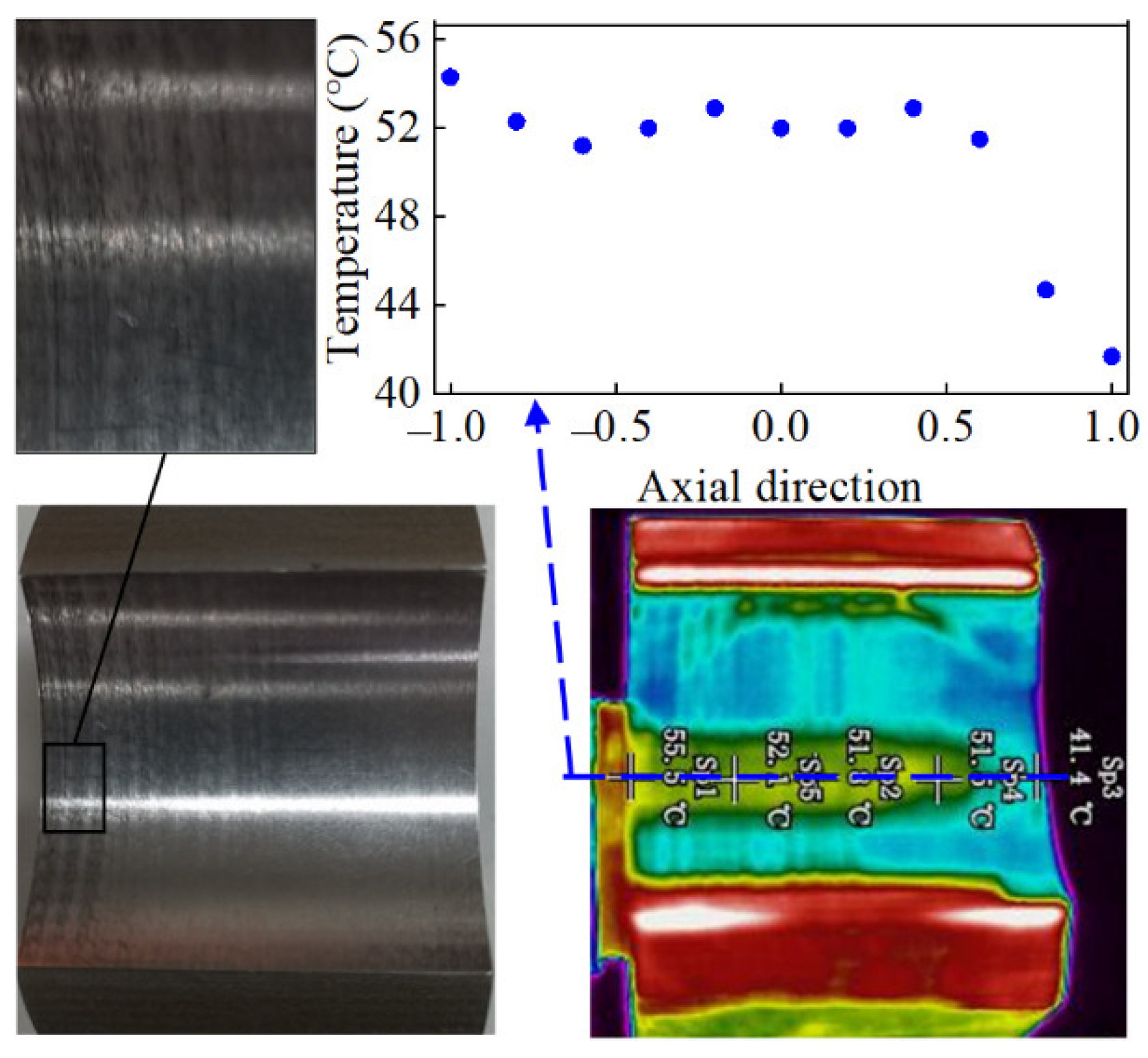
Journal misalignment was considered in the present experiment. Figure 21 and Figure 22 show the surface condition of the shaft and the bush after the experiment. The temperature field distribution was photographed by a thermal imager. There was an apparent wear phenomenon, especially on one side. Furthermore, the temperature distribution of the shaft and bush surface had a significant side end effect, and the maximum temperature of bush was achieved near the minimum oil film thickness position and maintained the same distribution trend as the theoretical results. The maximum temperature differences of the shaft and bush along the axial direction were about 5 °C and 12.6 °C, respectively. This also indicates that journal misalignment is common in actual work conditions.
6. Conclusions
In this paper, the effects of the misaligned journal on the mixed lubrication performances of journal bearing were investigated. The pressure field, temperature field, and bearing performance parameters were obtained. The calculated maximum pressure and bearing temperature reasonably agreed with the published results. Furthermore, an experiment was performed on an experimental machine. The following conclusions can be drawn:
- (1)
- Journal misalignment had a notable influence on the lubrication states, hydrodynamic pressure, and contact pressure. Under the aligned condition, the asperity contact pressure was larger at both sides due to the elastic deformation of the bearing. However, under the misaligned condition, the hydrodynamic pressure distribution skewed to one side, and the asperity contact pressure only occurred at one side of the bearing.
- (2)
- Temperature field distribution had a significant asymmetry along the axial direction and the temperature greatly increased with the misalignment because of the additional heat generated by asperity contact.
- (3)
- The frictional force showed a sharp rise with the increase in the misalignment angle. This also indicates that journal misalignment makes mixed lubrication occur easily. Furthermore, side leakage flow increased with the increase in the misalignment angle. The attitude angle on side-section and load capacity showed little variation within a small misalignment range.
- (4)
- The experiment results showed that the misalignment phenomenon had a notable influence on mixed lubrication between the journal and the bearing surface and caused the wear on one side.
This work is a valuable reference for the optimal design of lubrication performances considering journal misalignment and thermal effect, and is beneficial for the further study of the influence of wear on the mixed lubrication performances of bearings with journal misalignment.
Author Contributions
Conceptualization, H.G. and M.S.; Investigation, J.B.; Formal Analysis, S.Z.; Writing-Original Draft Preparation, J.B.; Writing—Review & Editing, H.G. and M.S.; Experiment, S.Z. and J.B. All authors have read and agreed to the published version of the manuscript.
Funding
Supported by the National Natural Science Foundation of China (Grant No. 52205222) and the China Postdoctoral Science Foundation (2021M692913).
Data Availability Statement
Data are contained within the article.
Conflicts of Interest
The authors have no competing interests to declare that are relevant to the contents of this article.
Nomenclature
| e | Eccentricity at axial mid-plane, (mm) |
| ε | Eccentricity ratio |
| α | Misalignment angle of axial direction, (°) |
| β | Misalignment angle of circumferential direction, (°) |
| r | Radius of shaft, (mm) |
| φ | Circumferential angle, (°) |
| R | Inner radius of bush, (mm) |
| p | Hydrodynamic pressure, (MPa) |
| t | Thickness of bearing layer, (mm) |
| h | Total nominal film thickness, (mm) |
| Average film thickness, (mm) | |
| c | Radial clearance, (mm) |
| ν0 | Poisson’s ratio |
| E | Modulus of elasticity, (GPa) |
| U | Linear velocity, (m/s) |
| l | Width of bearing, (mm) |
| φs | Shear flow factor |
| φx,φz | Pressure flow factor |
| σ | Surface roughness, (μm) |
| pc | Contact pressure, (MPa) |
| ρ | Lubricated oil density, (kg/m3) |
| κ | Thermal conductivity of oil, (W/m⋅°C) |
| cv | Specific heat of oil, (J/kg·K) |
| T | Temperature of oil, (°C) |
| T0 | Initial temperature of oil, (°C) |
| Tb | Temperature of bush, (°C) |
| fc | Boundary frictional coefficient |
| Ac | Contact area, (mm2) |
| A | Contact area, (mm2) |
| η | Viscosity of lubricant, (Pa·s) |
| rb | Radial coordinate of journal |
| Ts | Temperature of shaft, (°C) |
| kb | Thermal conductivity of bush, (W/m⋅°C) |
| Rb | Outside bearing radius, (mm) |
| Ta | Ambient temperature, (°C) |
| hb | Convection heat transfer coefficient, (W/m2⋅°C) |
| η0 | Initial viscosity of oil, (Pa·s) |
| α0 | Viscosity–pressure coefficient |
| β0 | Viscosity–temperature coefficient |
| χ | Asperity density |
| ξ | Curvature radius of asperity |
| F | Load carrying capacity, (N) |
| θ0 | Attitude angle of mid-section, (°) |
| Ff | Frictional force, (N) |
| Q | Leakage flow, (L/min) |
| Subscripts | |
| c | Contact |
| f | Friction |
| b | Bearing |
| s | Shaft |
| a | Ambient |
| E | Elastic |
| x,z | Circumferential, axial direction |
References
- Li, B.; Sun, J.; Zhu, S.; Fu, Y.; Zhao, X.; Wang, H.; Teng, Q.; Ren, Y.; Li, Y.; Zhu, G. Thermohydrodynamic lubrication analysis of misaligned journal bearing considering the axial movement of journal. Tribol. Int. 2019, 135, 397–407. [Google Scholar] [CrossRef]
- Shenoy, S.B.; Pai, R. Theoretical investigations on the performance of an externally adjustable fluid-film bearing including misalignment and turbulence effects. Tribol. Int. 2009, 42, 1088–1100. [Google Scholar] [CrossRef]
- Xie, Z.; Shen, N.; Zhu, W.; Tian, W.; Hao, L. Theoretical and experimental investigation on the influences of misalignment on the lubrication performances and lubrication regimes transition of water lubricated bearing. Mech. Syst. Signal Process. 2021, 149, 107211. [Google Scholar] [CrossRef]
- Lv, F.; Rao, Z.; Ta, N.; Jiao, C. Mixed-lubrication analysis of thin polymer film overplayed metallic marine stern bearing considering wall slip and journal misalignment. Tribol. Int. 2017, 109, 390–397. [Google Scholar] [CrossRef]
- Pei, J.; Han, X.; Tao, Y.; Feng, S. Mixed elastohydrodynamic lubrication analysis of line contact with Non-Gaussian surface roughness. Tribol. Int. 2020, 151, 106449. [Google Scholar] [CrossRef]
- Chong, W.W.F.; Hamdan, S.H.; Wong, K.J.; Yusup, S. Modelling Transitions in Regimes of Lubrication for Rough Surface Contact. Lubricants 2019, 7, 77. [Google Scholar] [CrossRef] [Green Version]
- De Kraker, A.; van Ostayen, R.A.J.; Rixen, D.J. Calculation of Stribeck curves for (water) lubricated journal bearings. Tribol. Int. 2007, 40, 459–469. [Google Scholar] [CrossRef]
- Liang, Y.; Gao, D.; Chen, B.; Zhao, J. Friction and Wear Study on Friction Pairs with a Biomimetic Non-smooth Surface of 316L Relative to CF/PEEK under a Seawater Lubricated Condition. Chin. J. Mech. Eng. 2019, 32, 66. [Google Scholar] [CrossRef] [Green Version]
- Zhu, S.; Sun, J.; Li, B.; Zhu, G. Thermal turbulent lubrication analysis of rough surface journal bearing with journal misalignment. Tribol. Int. 2020, 144, 106109. [Google Scholar] [CrossRef]
- Lv, F.; Ta, N.; Rao, Z. Analysis of equivalent supporting point location and carrying capacity of misaligned journal bearing. Tribol. Int. 2017, 116, 26–38. [Google Scholar] [CrossRef]
- Abdou, K.M.; Saber, E. Effect of rotor misalignment on stability of journal bearings with finite width. Alex. Eng. J. 2020, 59, 3407–3417. [Google Scholar] [CrossRef]
- Cui, S.; Gu, L.; Fillon, M.; Wang, L.; Zhang, C. The effects of surface roughness on the transient characteristics of hydrodynamic cylindrical bearings during startup. Tribol. Int. 2018, 128, 421–428. [Google Scholar] [CrossRef]
- Guo, Z.-W.; Yuan, C.-Q.; Bai, X.-Q.; Yan, X.-P. Experimental Study on Wear Performance and Oil Film Characteristics of Surface Textured Cylinder Liner in Marine Diesel Engine. Chin. J. Mech. Eng. 2018, 31, 52. [Google Scholar] [CrossRef] [Green Version]
- Zapletal, T.; Sperka, P.; Krupka, I.; Hartl, M. The effect of surface roughness on friction and film thickness in transition from EHL to mixed lubrication. Tribol. Int. 2018, 128, 356–364. [Google Scholar] [CrossRef]
- Prölß, M.; Schwarze, H.; Hagemann, T.; Zemella, P.; Winking, P. Theoretical and Experimental Investigations on Transient Run-Up Procedures of Journal Bearings Including Mixed Friction Conditions. Lubricants 2018, 6, 105. [Google Scholar] [CrossRef] [Green Version]
- Lv, F.; Zou, D.; Ta, N.; Rao, Z. Influence of local turbulent flow on the performance of a mixed-lubrication bearing. Proc. Inst. Mech. Eng. Part J J. Eng. Tribol. 2019, 233, 1029–1035. [Google Scholar] [CrossRef]
- Babu, P.V.; Ismail, S.; Ben, B.S. Experimental and numerical studies of positive texture effect on friction reduction of sliding contact under mixed lubrication. Proc. Inst. Mech. Eng. Part J J. Eng. Tribol. 2021, 235, 360–375. [Google Scholar] [CrossRef]
- Reddy, A.R.; Ismail, S. Tribological performance of textured parallel sliding contact under mixed lubrication condition by considering mass conservation condition and couple-stress parameter. Proc. Inst. Mech. Eng. Part J J. Eng. Tribol. 2021, 235, 410–422. [Google Scholar] [CrossRef]
- Xiang, G.; Han, Y.; He, T.; Wang, J.; Xiao, K.; Li, J. Transient tribo-dynamic model for journal bearings during start-up considering 3D thermal characteristic. Tribol. Int. 2020, 144, 106123. [Google Scholar] [CrossRef]
- Xie, Z.; Zhu, W. Theoretical and experimental exploration on the micro asperity contact load ratios and lubrication regimes transition for water-lubricated stern tube bearing. Tribol. Int. 2021, 164, 107105. [Google Scholar] [CrossRef]
- Sun, J.; Changlin, G. Hydrodynamic lubrication analysis of journal bearing considering misalignment caused by shaft deformation. Tribol. Int. 2004, 37, 841–848. [Google Scholar] [CrossRef]
- Sun, J.; Zhu, X.; Zhang, L.; Wang, X.; Wang, C.; Wang, H.; Zhao, X. Effect of surface roughness, viscosity-pressure relationship and elastic deformation on lubrication performance of misaligned journal bearings. Ind. Lubr. Tribol. 2014, 66, 337–345. [Google Scholar] [CrossRef]
- Jang, J.; Khonsari, M. On the Characteristics of Misaligned Journal Bearings. Lubricants 2015, 3, 27–53. [Google Scholar] [CrossRef] [Green Version]
- Zhang, X.; Yin, Z.; Jiang, D.; Gao, G.; Wang, Y.; Wang, X. Load carrying capacity of misaligned hydrodynamic water-lubricated plain journal bearings with rigid bush materials. Tribol. Int. 2016, 99, 1–13. [Google Scholar] [CrossRef]
- Das, S.; Guha, S.K. Numerical analysis of steady-state performance of misaligned journal bearings with turbulent effect. J. Braz. Soc. Mech. Sci. Eng. 2019, 41, 81. [Google Scholar] [CrossRef]
- Manser, B.; Belaidi, I.; Hamrani, A.; Khelladi, S.; Bakir, F. Performance of hydrodynamic journal bearing under the combined influence of textured surface and journal misalignment: A numerical survey. Comptes Rendus Mécanique 2019, 347, 141–165. [Google Scholar] [CrossRef]
- Zhang, Y.; Chen, G.; Wang, L. Thermoelastohydrodynamic analysis of misaligned bearings with texture on journal surface under high-speed and heavy-load conditions. Chin. J. Aeronaut. 2019, 32, 1331–1342. [Google Scholar] [CrossRef]
- Xiang, G.; Han, Y.; Wang, J.; Xiao, K.; Li, J. A transient hydrodynamic lubrication comparative analysis for misaligned micro-grooved bearing considering axial reciprocating movement of shaft. Tribol. Int. 2019, 132, 11–23. [Google Scholar] [CrossRef]
- Zheng, L.; Zhu, H.; Zhu, J.; Deng, Y. Effects of oil film thickness and viscosity on the performance of misaligned journal bearings with couple stress lubricants. Tribol. Int. 2020, 146, 106229. [Google Scholar] [CrossRef]
- Lv, F.; Jiao, C.; Ta, N.; Rao, Z. Mixed-lubrication analysis of misaligned bearing considering turbulence. Tribol. Int. 2018, 119, 19–26. [Google Scholar] [CrossRef]
- Jang, J.Y.; Khonsari, M.M. On the wear of dynamically-loaded engine bearings with provision for misalignment and surface roughness. Tribol. Int. 2020, 141, 105919. [Google Scholar] [CrossRef]
- Mokhiamer, U.M.; Crosby, W.A.; El-Gamal, H.A. A study of a journal bearing lubricated by fluids with couple stress considering the elasticity of the liner. Wear 1999, 224, 194–201. [Google Scholar] [CrossRef]
- Patir, N.; Cheng, H.S. An average flow model for determining effects of three-dimensional roughness on partial hydrodynamic lubrication. J. Lubr. Technol.-Trans. ASME 1978, 100, 12–17. [Google Scholar] [CrossRef]
- Bukovnik, S.; Offner, G.; Čaika, V.; Priebsch, H.H.; Bartz, W.J. Thermo-elasto-hydrodynamic lubrication model for journal bearing including shear rate-dependent viscosity. Lubr. Sci. 2007, 19, 231–245. [Google Scholar] [CrossRef]
- Greenwood, J.A.; Tripp, J.H. The Contact of Two Nominally Flat Rough Surfaces. Proc. Inst. Mech. Eng. 1970, 185, 625–633. [Google Scholar] [CrossRef]
Figure 1.
Journal bearing structure with misalignment.
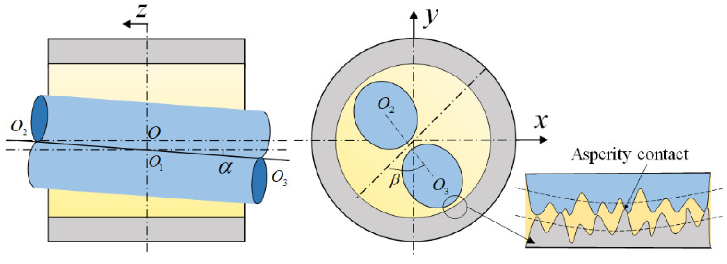
Figure 2.
Geometrical relationship of the axial section.
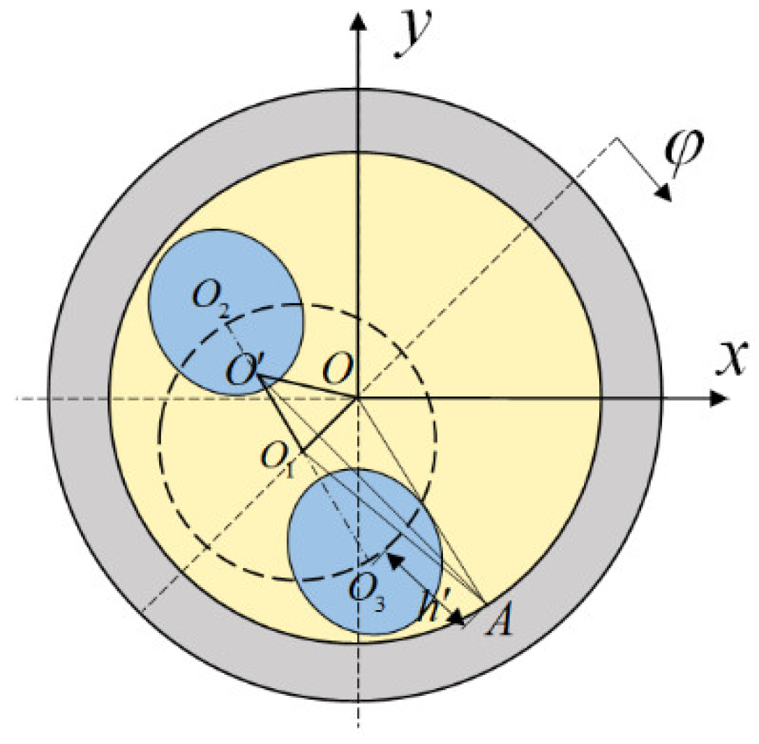
Figure 3.
Thermal boundary conditions.

Figure 4.
Flow chart of the M-TEHD analysis of misaligned bearing.

Figure 5.
The circumferential temperature compared with reference [15].
Figure 5.
The circumferential temperature compared with reference [15].

Figure 6.
The influence of journal misalignment on the lubrication states.

Figure 7.
Distribution of the geometry clearance and pressure field of the journal bearing with different misalignment angle (ε = 0.8).
Figure 7.
Distribution of the geometry clearance and pressure field of the journal bearing with different misalignment angle (ε = 0.8).
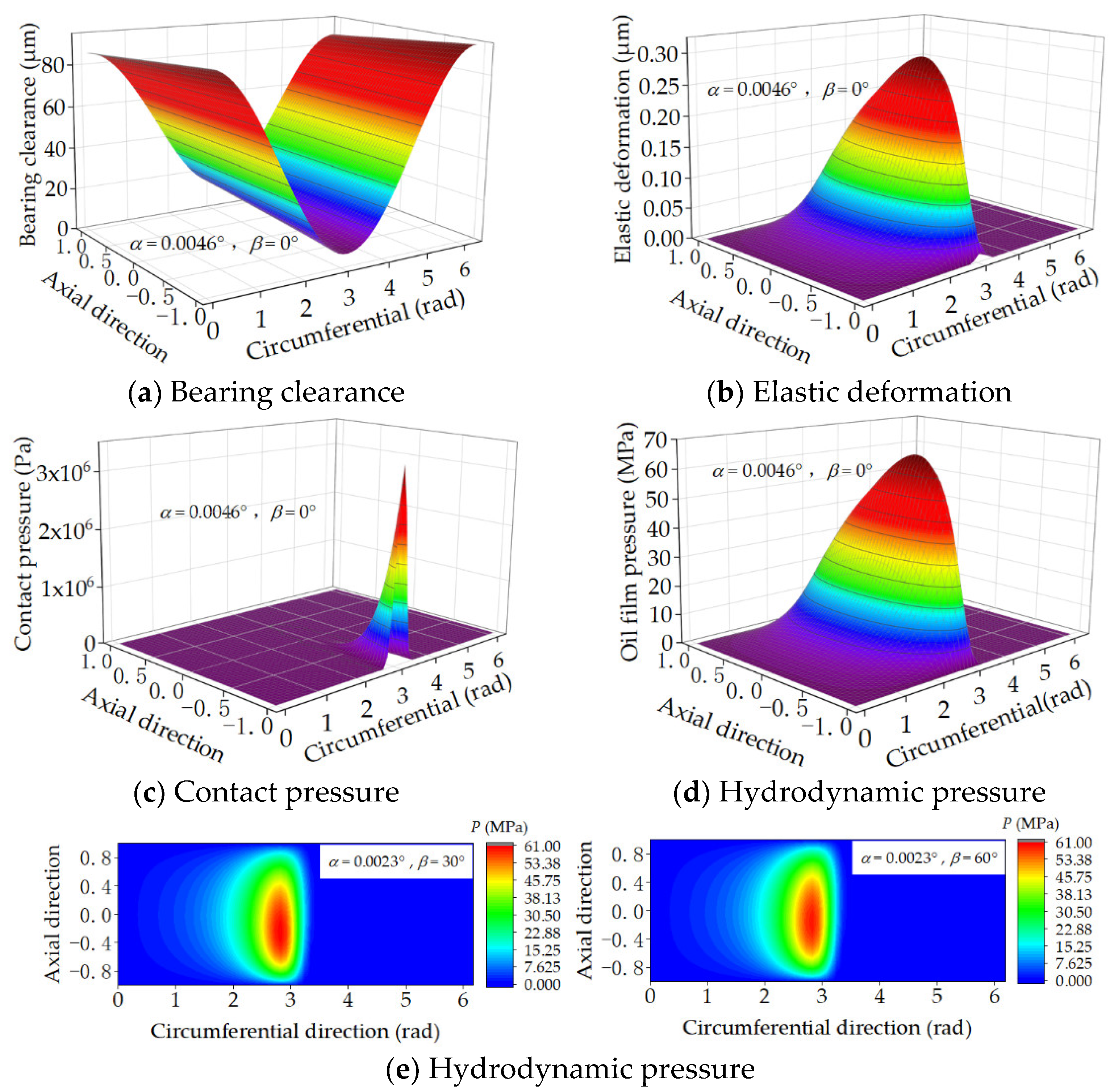
Figure 8.
Pressure distribution at the axial section with a different degree of misalignment (ε = 0.8).
Figure 8.
Pressure distribution at the axial section with a different degree of misalignment (ε = 0.8).
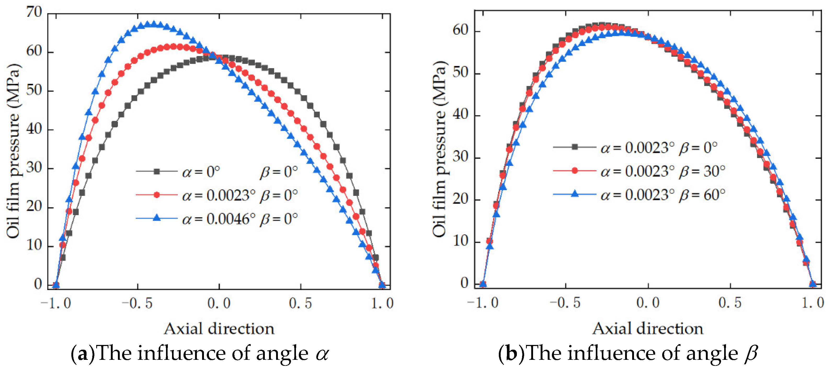
Figure 9.
Temperature field performances of the circumferential direction.

Figure 10.
Temperature field performances of the axial direction.
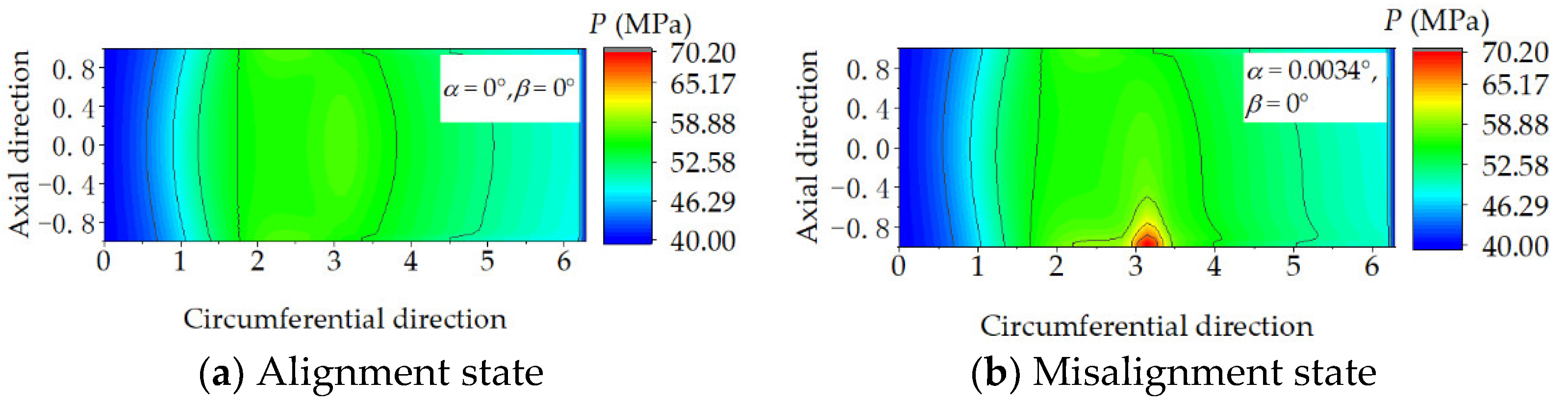
Figure 11.
Temperature distribution at the axial direction.
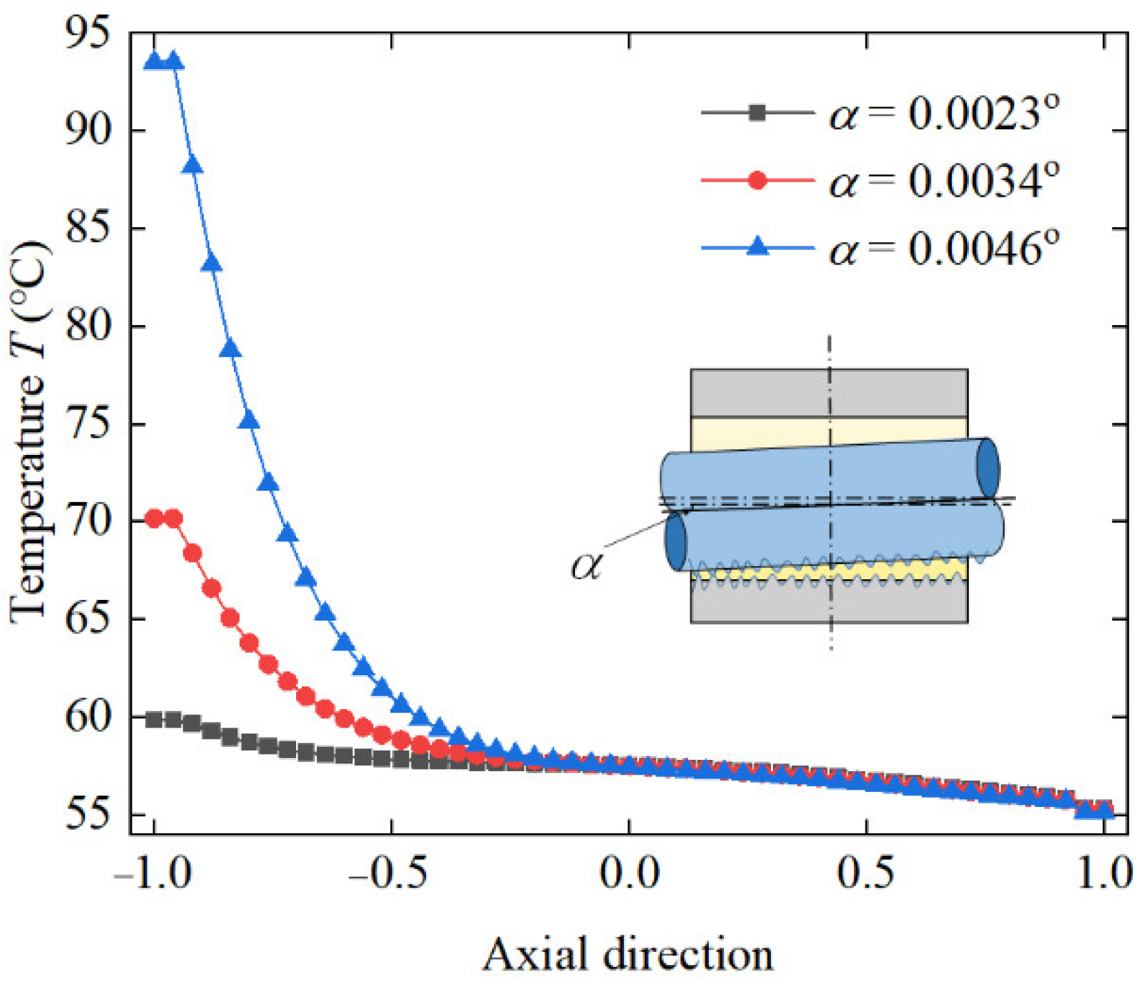
Figure 12.
Maximum temperature with different eccentricity.
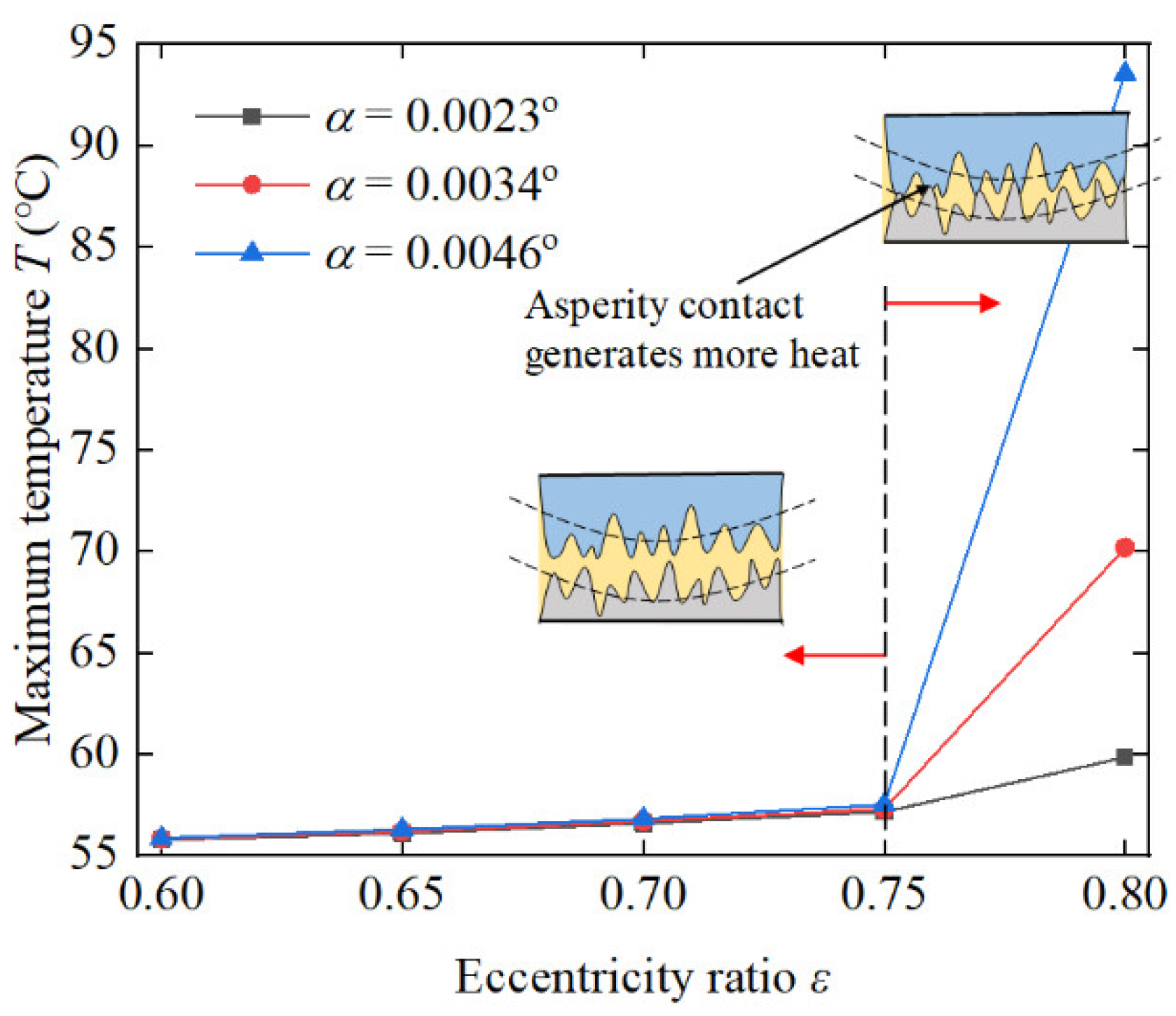
Figure 13.
Variation in the attitude angle with different ε and α.

Figure 14.
Variation in the load capacity with different ε and α.
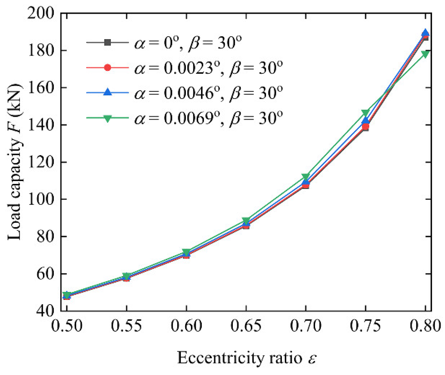
Figure 15.
Variation in the frictional force with different ε and α.

Figure 16.
Variation in the side leakage flow with different ε and α.
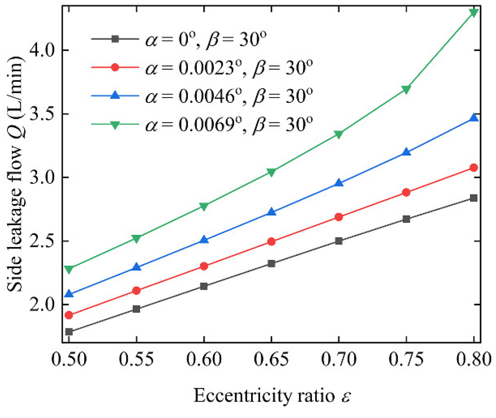
Figure 17.
Physical illustration of the equipment.
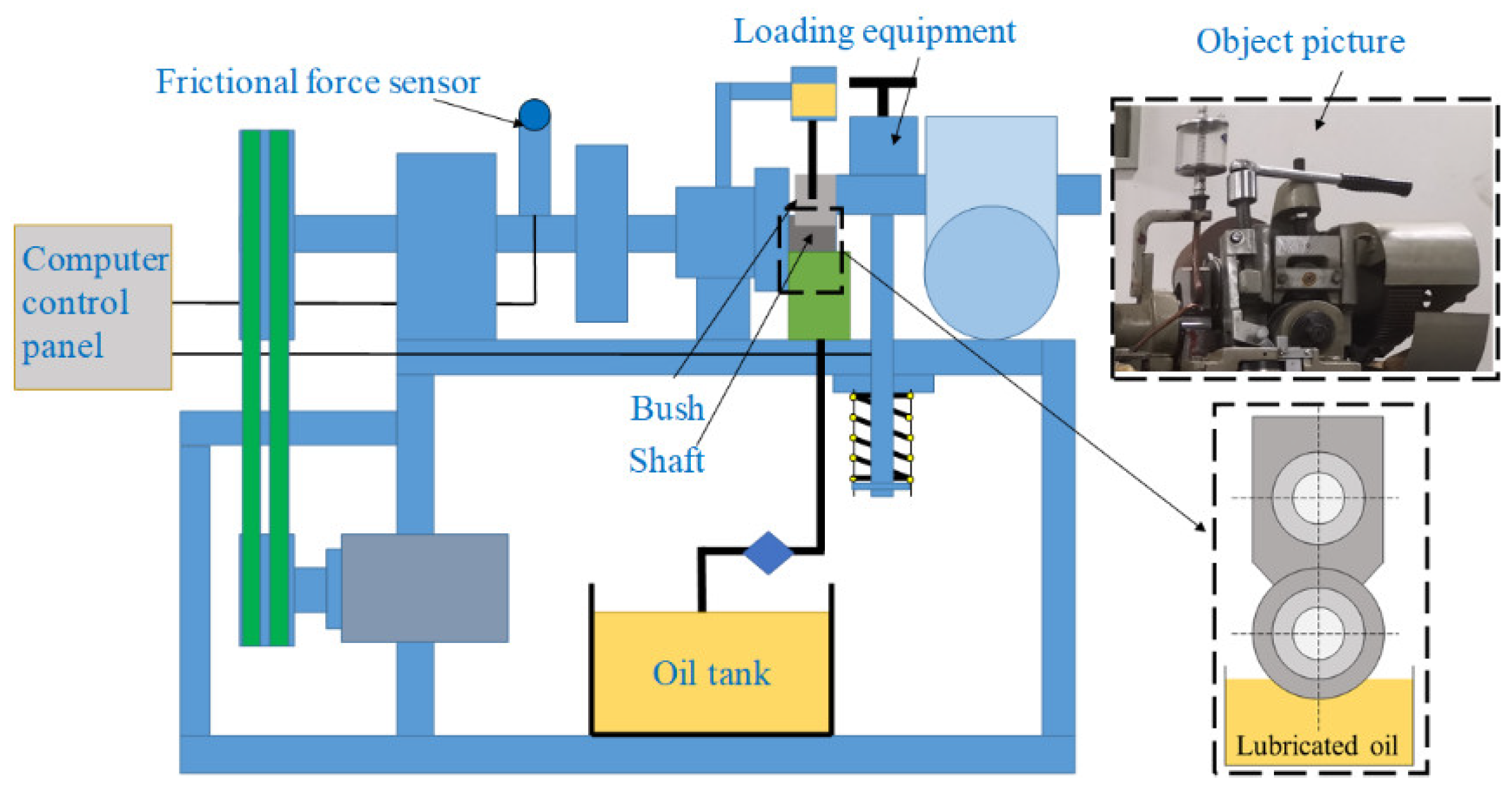
Figure 18.
Bush and shaft structure.
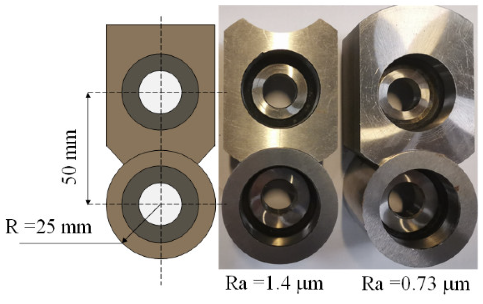
Figure 19.
The frictional force measured of different specimens.
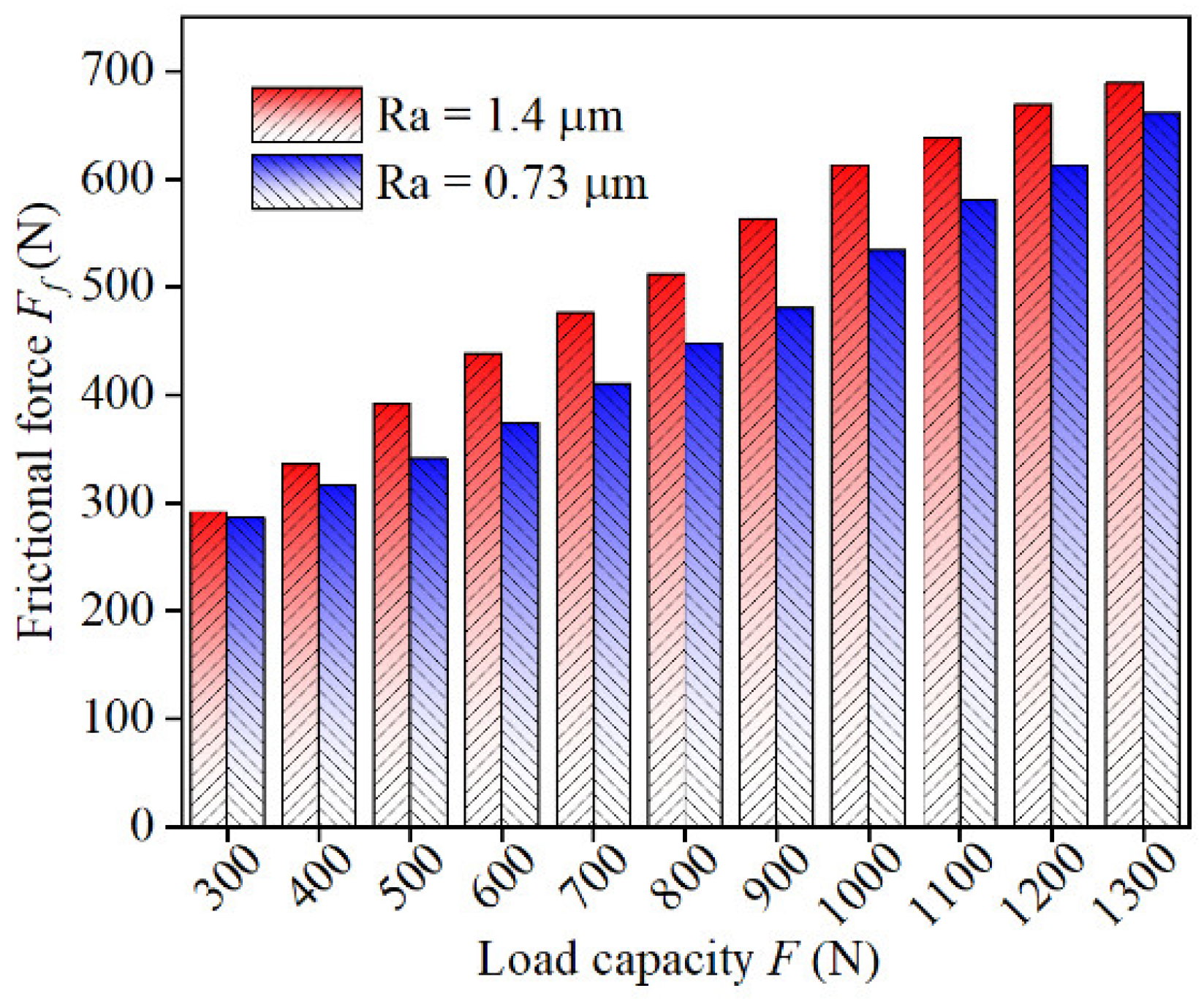
Figure 20.
The frictional coefficient measured of different specimens.
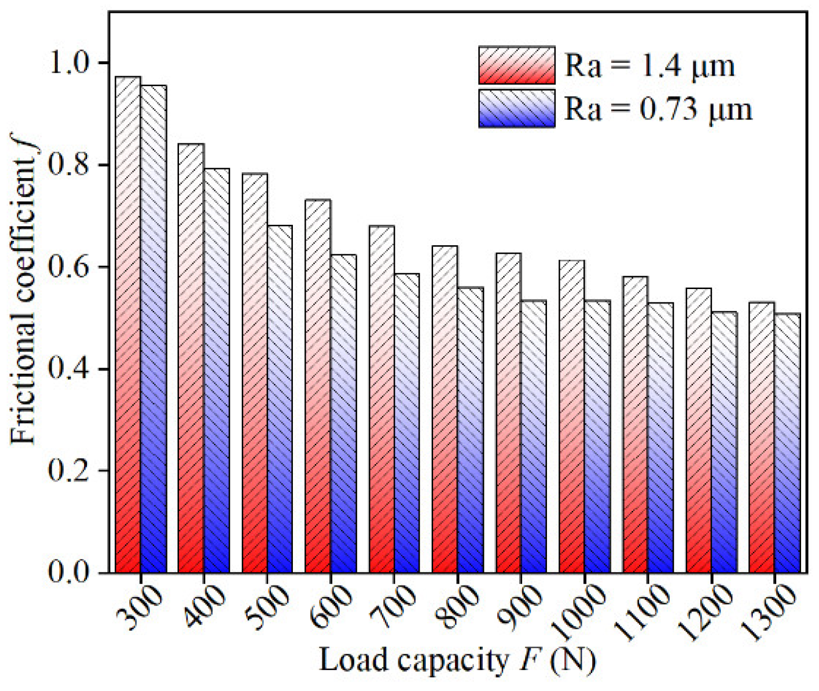
Figure 21.
The shaft surface after the experiment.
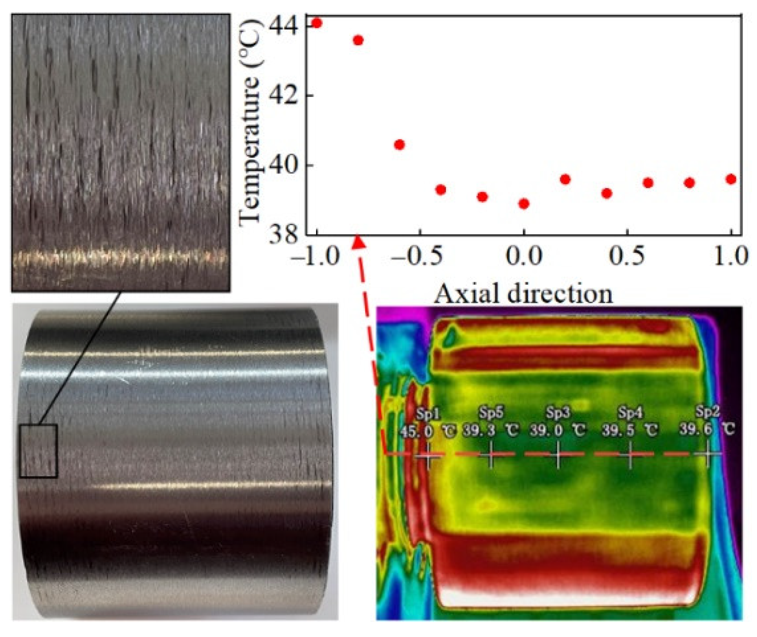
Figure 22.
The bush surface after the experiment.

Table 1.
The calculated maximum oil film pressure versus the inclined angle.
| α (Degree) | Value in Reference [21] (MPa) | Present Work (MPa) | Relative Error |
|---|---|---|---|
| 0 | 33.06 | 30.43 | 7.9% |
| 0.004 | 39.6 | 36.21 | 8.56% |
| 0.007 | 63.58 | 57.0 | 10.35% |
Table 2.
The main parameters of the bearing and lubricant.
| Parameters | Valves | Parameters | Valves |
|---|---|---|---|
| Journal radius | 50.0 mm | Oil inlet temperature | 40 °C |
| Bush outer radius | 100.0 mm | Ambient temperature | 30 °C |
| Bearing length | 100.0 mm | Rotational speed | 3000 rpm |
| Relative clearance | 1.0‰ | Bush thermal conductivity | 250 W/m°C |
| Lubricant density | 860 kg/m3 | Lubricant specific heat | 1906 J/kg·K |
| Lubricant viscosity | 0.027 Pa·s | Convection heat transfer coefficient | 80 W/m2·°C |
| Lubricant thermal conductivity | 0.13 W/m·°C | Surface roughness | 2.4 μm |
| Viscosity–pressure coefficient | 2.2 × 10⁻⁸ | Viscosity–temperature coefficient | 0.035 |
| Integrated elasticity modulus | 210 GPa |
Publisher’s Note: MDPI stays neutral with regard to jurisdictional claims in published maps and institutional affiliations. |
© 2022 by the authors. Licensee MDPI, Basel, Switzerland. This article is an open access article distributed under the terms and conditions of the Creative Commons Attribution (CC BY) license (https://creativecommons.org/licenses/by/4.0/).
Share and Cite
MDPI and ACS Style
Guo, H.; Bao, J.; Zhang, S.; Shi, M. Experimental and Numerical Study on Mixed Lubrication Performance of Journal Bearing Considering Misalignment and Thermal Effect. Lubricants 2022, 10, 262. https://doi.org/10.3390/lubricants10100262
AMA Style
Guo H, Bao J, Zhang S, Shi M. Experimental and Numerical Study on Mixed Lubrication Performance of Journal Bearing Considering Misalignment and Thermal Effect. Lubricants. 2022; 10(10):262. https://doi.org/10.3390/lubricants10100262
Chicago/Turabian StyleGuo, Hong, Jianqiao Bao, Shaolin Zhang, and Minghui Shi. 2022. "Experimental and Numerical Study on Mixed Lubrication Performance of Journal Bearing Considering Misalignment and Thermal Effect" Lubricants 10, no. 10: 262. https://doi.org/10.3390/lubricants10100262
Note that from the first issue of 2016, this journal uses article numbers instead of page numbers. See further details here.