Article

The Improvement of the Wear Resistance of T15 Laser Clad Coating by the Uniformity of Microstructure

1
College of Mechanical & Electrical Engineering, Hohai University, Changzhou 213022, China
2
Beijing Key Lab of Precision/Ultra-Precision Manufacturing Equipments and Control, Tsinghua University, Beijing 100084, China
3
DANTE Solutions, Inc., Cleveland, OH 44130, USA
*
Author to whom correspondence should be addressed.
Lubricants 2022, 10(10), 271; https://doi.org/10.3390/lubricants10100271
Submission received: 9 September 2022 / Revised: 7 October 2022 / Accepted: 18 October 2022 / Published: 20 October 2022
(This article belongs to the Special Issue Laser Surface Engineering for Tribology)

Abstract

:
The uniformity of microstructure and wear properties exist in the T15 coating for the laser cladding on 42CrMo steel. It can be improved by a post-heat treatment process. Temperature ranges from 1100 to 1240 °C were applied on the cladding layer to investigate the effect of the heat treatment on the wear resistance and hardness gradient. The post-heat treatment can efficiently improve the inhomogeneity of microstructure. The lower wear rate is obtained after the quenching process at 1100 °C, and the wear rate is increased though the tempering process. The carbides at the grain boundary are decomposed and integrated into the matrix during the high temperature quenching process. The carbides are precipitated and dispersed in the grain during the tempering process. The content of martensite and alloy carbide is significantly increased through the heat treatment process. The microhardness of the cladding layer is 910 HV after quenching and 750 HV after tempering. The wear mechanism of the cladding layer is mainly abrasive wear and fatigue wear. The crack and falling off from cladding layers are significantly reduced for the quenching–tempering process.

1. Introduction

42CrMo steel was widely used in the manufacturing of driving gear rings for tracked vehicles. Due to the high load and poor working conditions, the higher hardness and strong wear resistance was required for the part’s surface [1]. As an advanced coating preparation and surface modification technology, laser cladding provided an effective solution for the multifunctional coating with higher hardness and better wear resistance for the common alloy steel [2]. The fine grain structure, small heat affected zone and matrix deformation could be achieved by using a laser cladding process [3]. The life and surface properties were promoted by the laser cladding process with relatively small consumption of high-performance materials [4,5,6,7].
The wear rate could be decreased remarkably by cladding different materials with high strength and wear resistance [8,9,10]. The surface wear resistance was 2.4 times the original 42CrMo steel by applying the NiCrBSi/Mo composite coating for the roller [11]. The weight loss of NiCr-TiC composite cladding layer is 1/3 of the stainless steel substrate [12]. As a high-speed steel, T15 is applied broadly in cutting tools, stamping dies and other manufacturing fields, because of its high strength, high hardness and excellent wear resistance [13,14,15].
As defects formed in the coating layer during the laser cladding process, the optimization of process parameters and material alloy composition was the key study point [16]. The average grain size and porosity of the cladding layer are reduced by ultrasonic-assisted vibration [17]. The cracking phenomenon of T-800 coating improved laser cladding assisted with pre-heat [18]. The Ni60 laser cladding layer with refined grains and no crack can be obtained by applying CeO2 and Y2O3 [19].
The distribution of alloying elements was inhomogeneous in the coating under the rapid heating and cooling rate [20,21]. The inhomogeneity distribution of alloy composition and microstructure had great influence on the coating hardness and wear resistance [22,23,24,25,26].
The microstructures of the heat-affected zone (HAZ) and properties of the cladding layer could be improved by the post-heat treatment [27]. The phase proportion of FeCoCrNiAlx laser-cladding laser layer could be controlled by using auxiliary heat treatment, resulting in the effective improvement for the mechanical properties [28].
In this paper, the inhomogeneity of T15 coating on 42CrMo steel was studied and the post-heat treatment was put forward to improve the microstructure uniformity and tribological properties of the cladding layer. The microstructure, phase, hardness and tribological properties were analyzed for the original and heat-treated coatings. The wear mechanisms of the coatings were also investigated.

2. Experimental Methods

42CrMo steel was used as the substrate with the dimension of 100 × 100 × 10 mm. Before the laser cladding experiment, the oxide layer and oil stain on the surface should be removed. T15 powder with the particle size of 50~80 µm was selected as the coating matrix powder, as shown in Figure 1. The powder was heated in a vacuum drying box at 90 °C for 2 h. The chemical compositions were obtained by a direct-reading spectrometer for 42CrMo and by ICP-OES for the T15 powder, and the testing results are shown in Table 1.
The laser cladding experimental equipment was a Disk laser (TruDisk 4002, Trumpf, Ditzingen, Germany) and a KUKA robot system (KR60-3, KUKA, Augsburg, Germany). Argon gas was used as the powder carrier and protective gas to prevent the melt pool from oxidizing. The protective gas flow was 20 L/min [29]. T15 cladding layer thickness was about 1 mm. The process parameters of laser cladding are shown in the Table 2. After cladding, the coatings were cut into small specimens with size 10 × 10 × 10 mm by wire cutting for heat treatment and further analysis.
The cladding samples were heated by muffle furnace (FB, IRM, Lilienthal, Germany). The cladding layer was quenched at 1100 °C, 1190 °C and 1240 °C, respectively, to study its effect on the microstructure uniformity and wear resistance of the cladding layer. The process parameters of heat treatment were shown Figure 2.
The hardness of samples was tested by the Vickers hardness tester (HVS-1000A, Huayin, Laizhou, China). The test load was 300 g and the loading time was 15 s. Twenty points with an interval of 0.1 mm were measured continuously, and the average value of three times was taken as the hardness value of this point.
The dry sliding wear properties at room temperature were tested by a CFT-Ⅰ friction and wear testing system (CFT-Ⅰ, Zhongke Kaihua, Lanzhou, China). The test configuration is schematically illustrated in Figure 3. The grinding ball was YG6 with a hardness of 93 HRC and a diameter of 6 mm. The wear mark is located in the middle of the non-overlapping area. The test conditions are shown in Table 3.
The wear volume (V) was measured by the contour scanning instrument. The wear volumes were calculated by using the equation: where V was the volume loss (mm3), L is the experimental load (N) and S is total test distance (m). The test configuration is schematically illustrated in Figure 4.
From the calculated wear volume, the wear rates were evaluated using the following Equation (1) [30].
W = V L × S
The microstructures and morphology of the wear trace were characterized by the scanning electron microscope (SEM, ZEISS, Sigma500, Oberkochen, Germany) equipped with energy dispersive spectroscopy (EDS) analysis system. The phase of the coating was identified by X-ray diffraction (XRD, Empyrean, Panaco, Almelo, Holland).

3. Results and Discussion

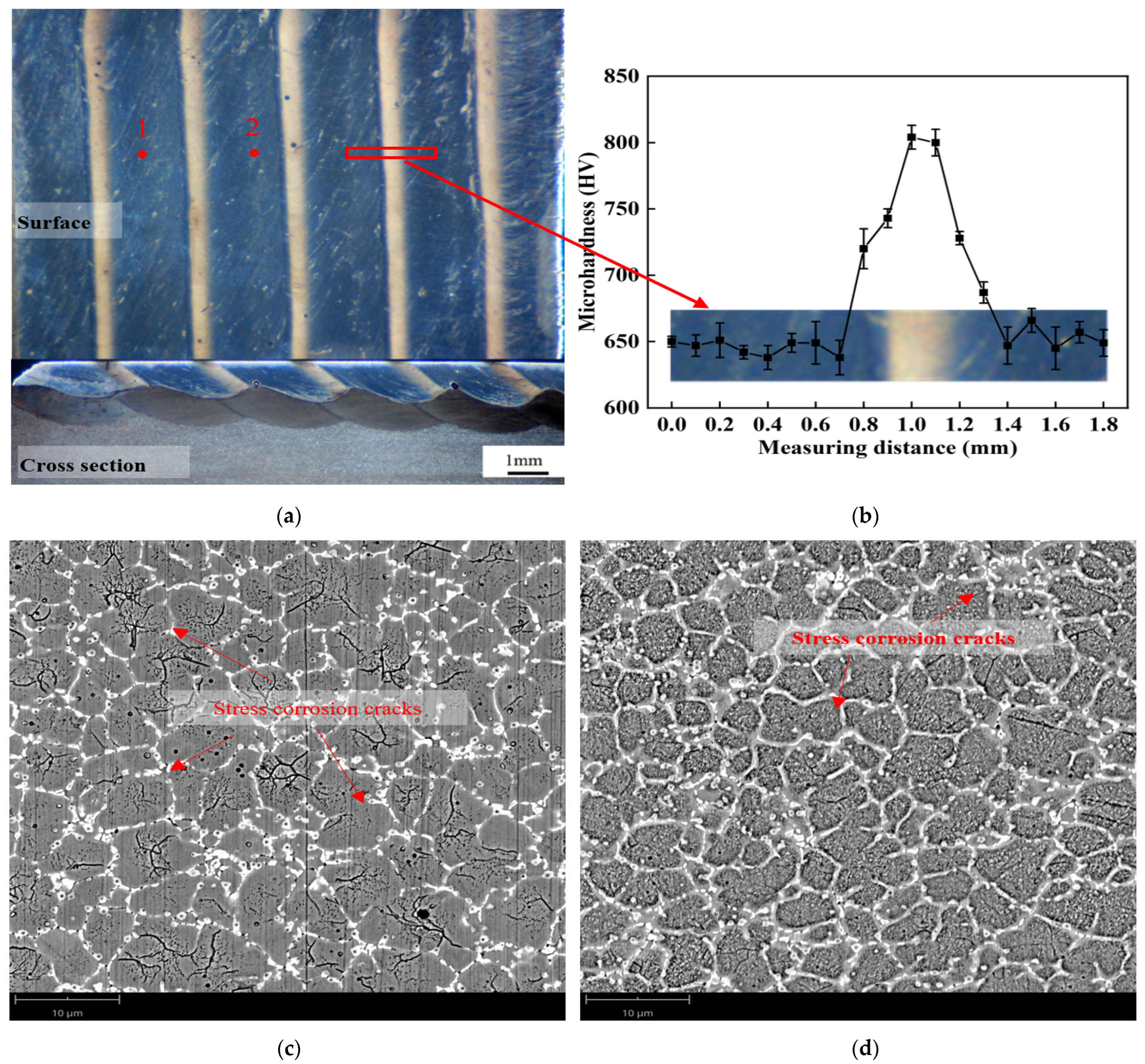
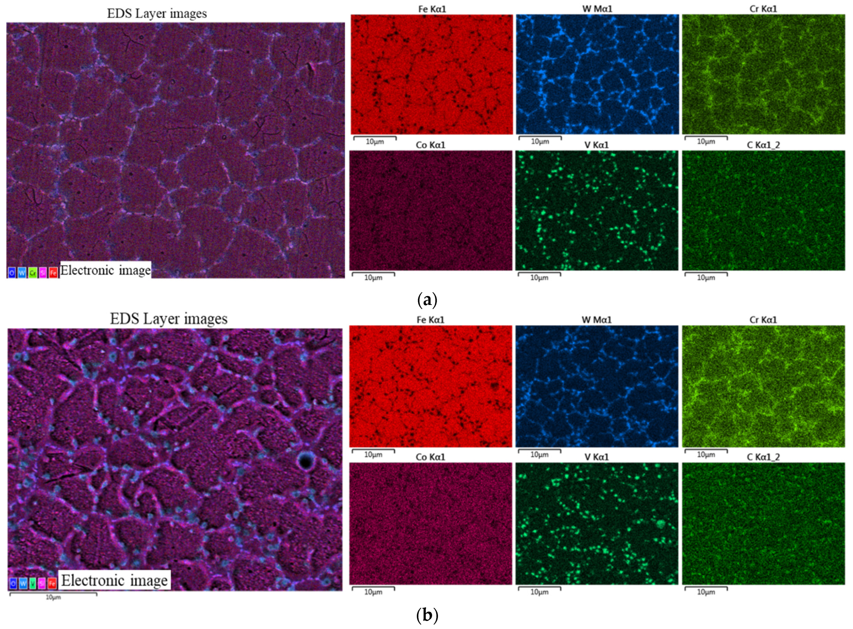
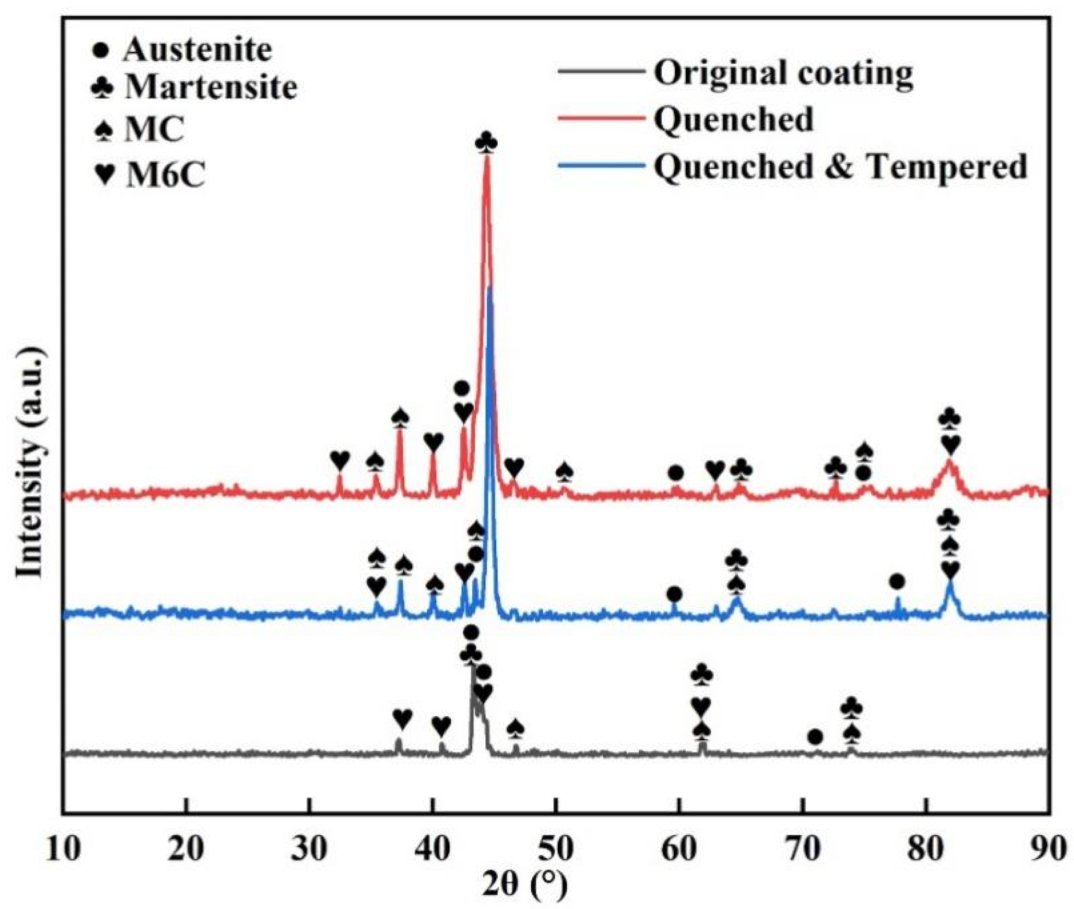
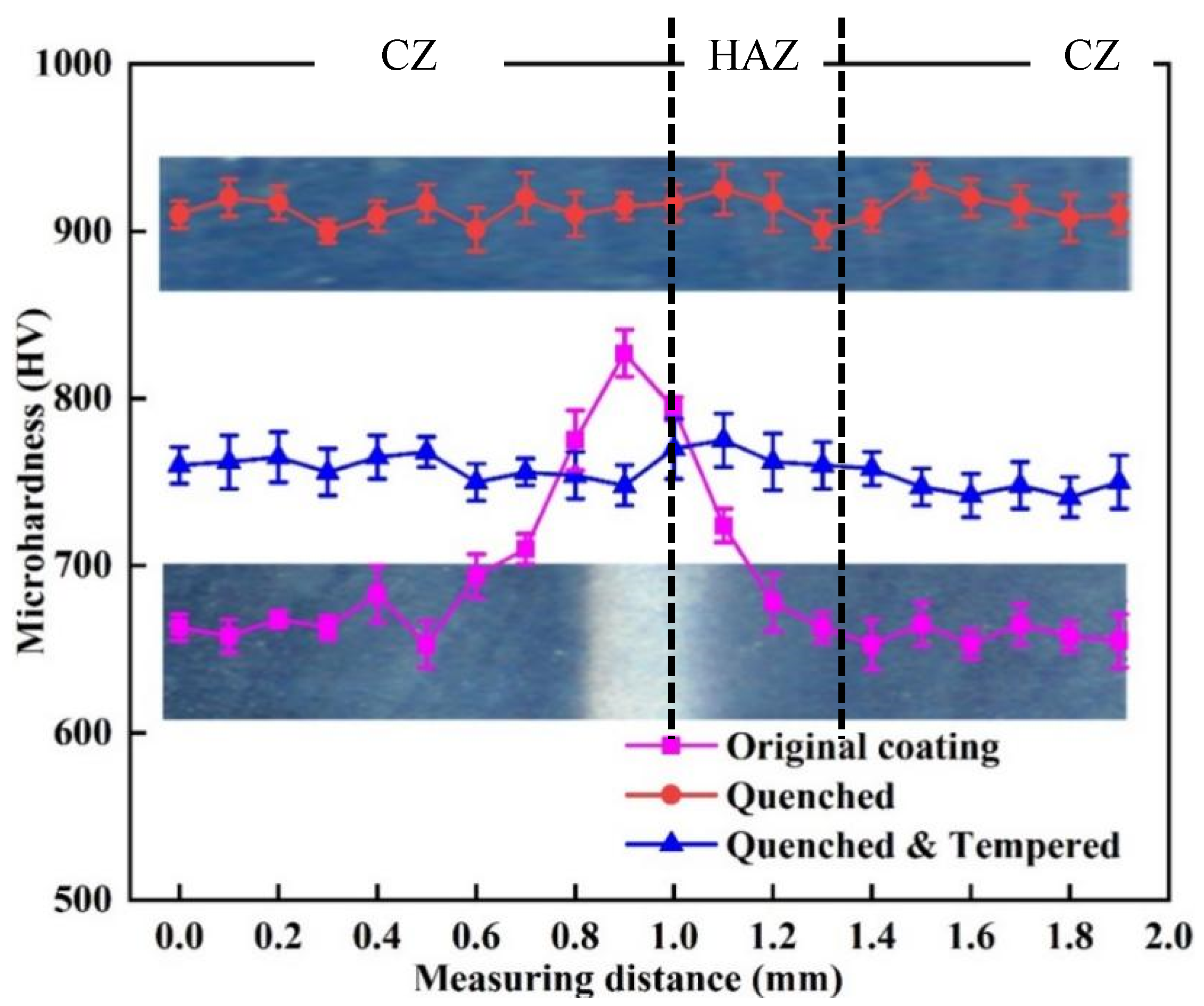
3.1. Microstructures and Hardness

After grinding, polishing and corrosion, there were obvious “black-and-white” areas on the surface of all cladding layers. The macro morphology of sample 1 was shown in Figure 5a. The “black-and-white” areas were marked as position 1 and 2, respectively. It can be found from Figure 5b that there was a large hardness gradient on the coating surface. Figure 5c,d showed microstructure of the T15 coating at positions 1 and 2. The coating was mainly composed of the equiaxed crystal and alloy carbides. The average size of grain size at position 2 was about 3.8 μm, which was much smaller than at position 1 with about 7 μm. The network alloy carbides were situated on the grain boundary, because alloy elements were excluded to the grain boundary in the process of forming equiaxed crystals [31]. The number of stress corrosion cracks at position 1 were more than position 2, which were formed at the combined action of large residual tensile stress and acid corrosive agent [32].
Figure 6 shows the surface scanning results of EDS at positions 1 and 2, respectively. Element segregation existed in both “black-and-white” areas of the cladding layer. A large number of W, V and Cr elements were enriched at the grain boundary [33], because these alloy elements with larger atomic radius were difficult to be a solid soluble with iron element [31]. However, the Co element was companied with the Fe element distributed in the inner grain. The lattice structure, atomic radius and electronic structure of the Co element may be similar to that of the Fe element in the matrix [34].

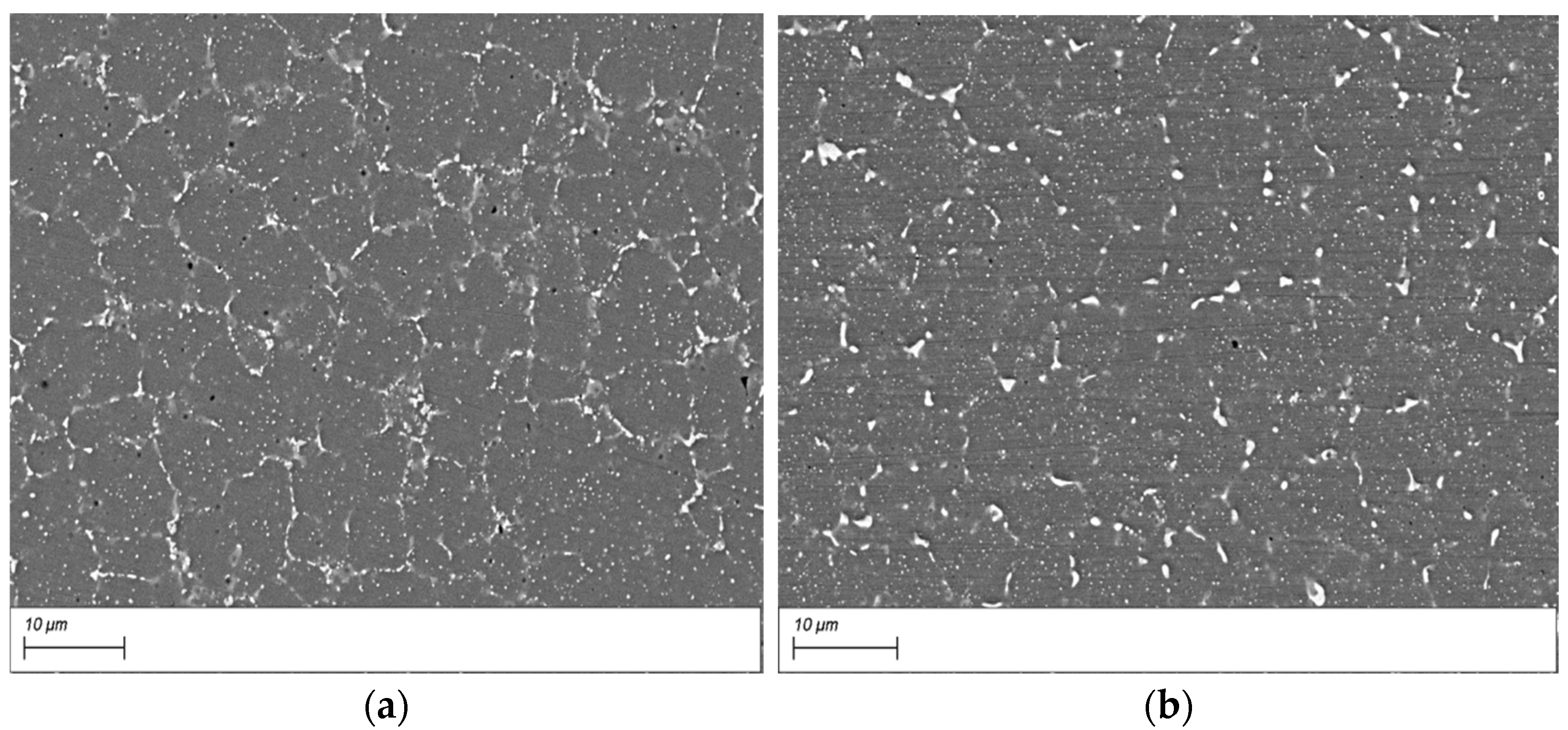
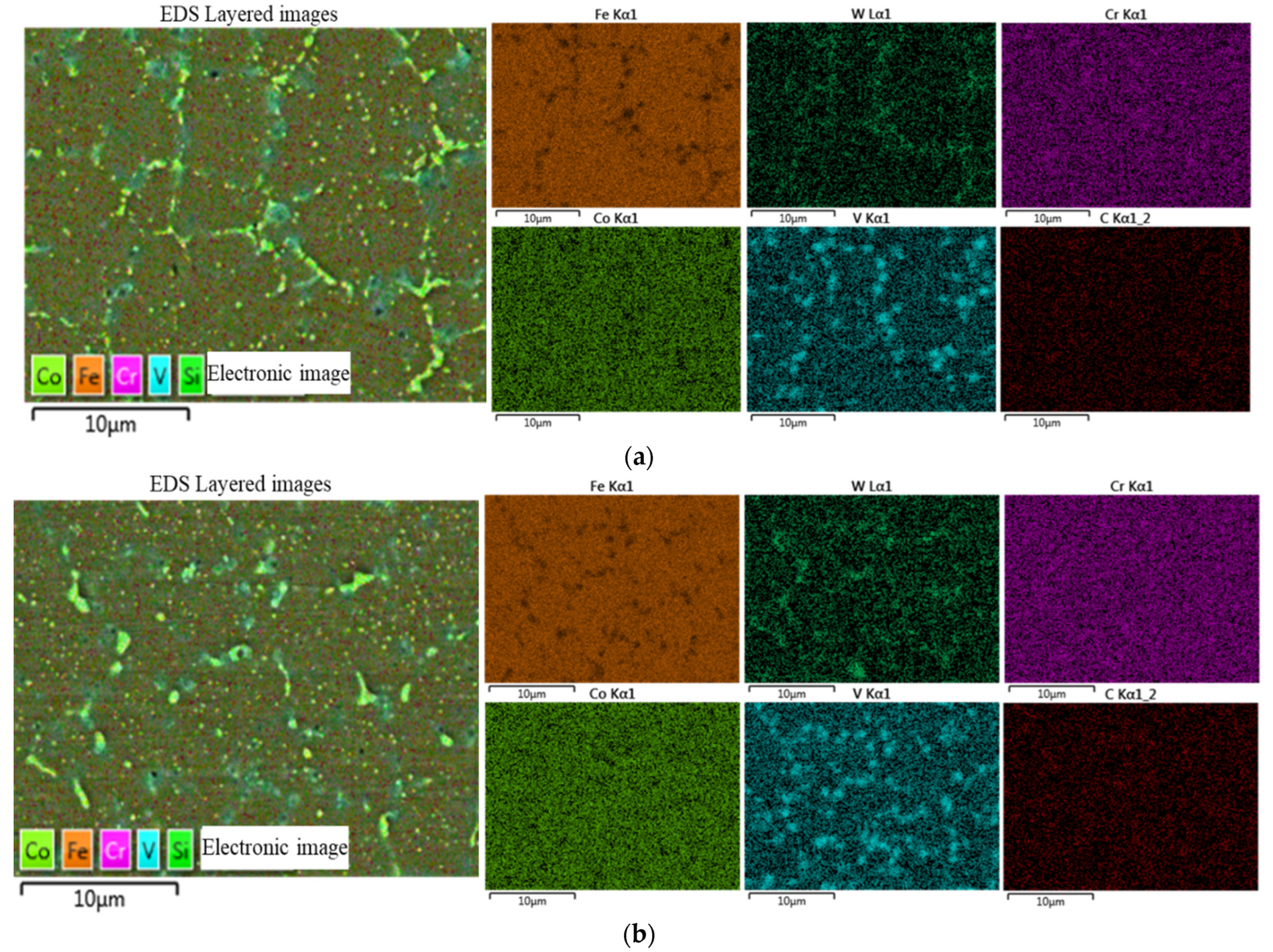
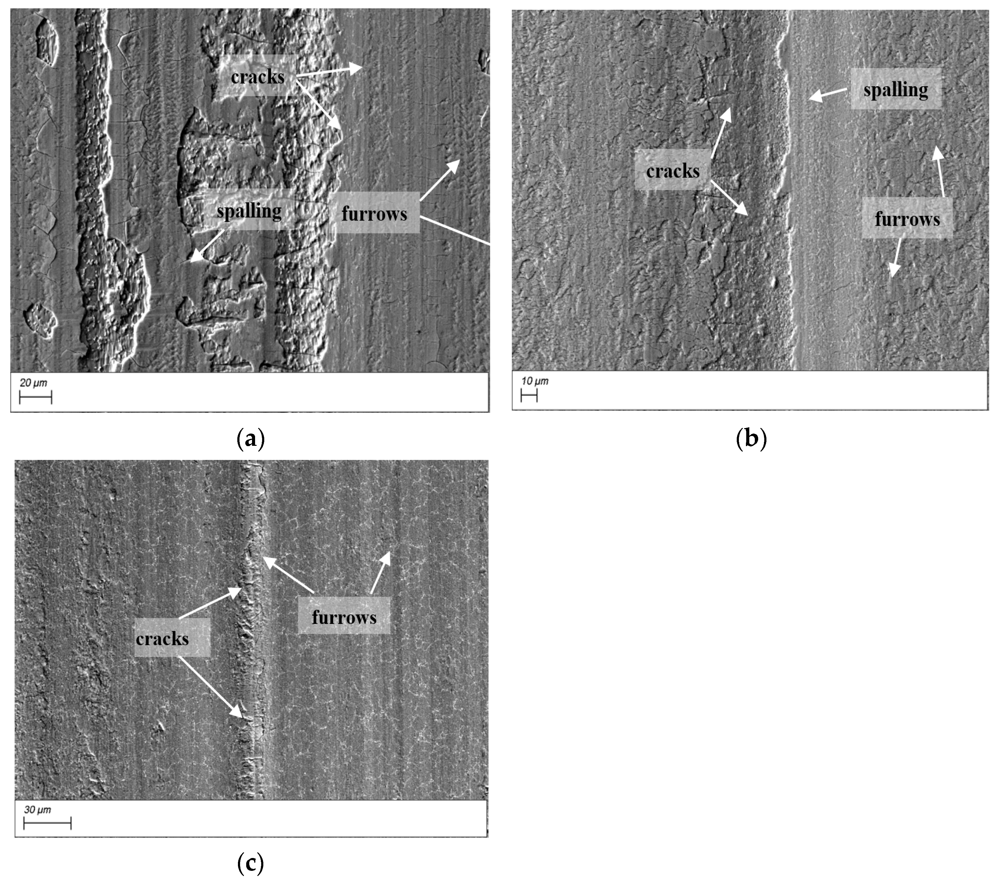
3.2. SEM Morphology after Quenching

A multi-channel transverse lap model was constructed, as shown in Figure 7. A heat-affected zone (HAZ) was only formed on the 42CrMo matrix during the first cladding surface. In subsequent cladding, the number of HAZ was changed because of the remelting zone (RZ). One HAZ was located on the arc surface of the prior cladding layer and the other was located on the 42CrMo substrate. Combined with the macro morphology of the coating, it was speculated that the black area was cladding zone (CZ) and the white bright zone was the HAZ of the arc surface of the front cladding layer.
Figure 8 shows the surface macro morphology of sample 1 after different quenching temperatures. The “black-and-white” area of the coatings surface and cross-section was eliminated after quenching. The structural uniformity of the coating was improved because the alloy carbides and elements were melted into the matrix and uniformly precipitated again at high temperature quenching [35].
According to the wear rate of sample 1 at different quenching temperatures (shown in Table 4), it can be clearly seen that the wear resistance of the coating can be further improved after quenching at 1100 °C. Therefore, the following focused on the changes of microstructure, hardness and tribological performance of cladding layers at 1100 °C quenching.
For the quenched coating (1100 °C), there was no significant difference in microstructure at scanning electron microscope. The surface microstructure of the cladding layer was shown as in Figure 9a. During the process of high temperature quenching, the network alloy carbides were gradually dissolved on the grain boundary of the cladding layer. A large number of fine carbides gradually integrated into the matrix. Some unmelted particles may be VC because of their high melting point [36].
After quenching, there were a lot of residual stress, retained austenite and brittle phases in the cladding layer. Tempering was immediately carried out to avoid cracks. Figure 9b shows the microstructure of the quenched cladding layer after tempering treatment. A large number of carbides in the grains of the cladding layer were uniformly distributed on the matrix, which were mainly spherical and very small in size.
As shown in Figure 10a,b, the Fe, W, Cr, and Co alloying elements were uniformly distributed except for the V element after post-heat treatment, which was consistent with the above guess of class V carbides.
Figure 11 shows the XRD patterns of the original and heat-treated T15 cladding layer. The phases of original CZ and HAZ could not be measured, respectively, due to the large diameter of diffraction spot. Therefore, the phases of two different regions were not distinguished. The phases compositions of the coatings after heat treatment were similar to those of the original coating, which mainly consisted of martensite, austenite, MC and M6C carbide. The percentage of alloy carbide increased obviously after the quenching and tempering process, for the reason of the secondary precipitation of carbide during heat treatment. Compared with the original cladding layer, the martensite diffraction peak of heat-treated cladding shifted to the right and changed from double-peak to single-peak, which indicated that the martensite structure had been changed by the heat treatment.
As seen from Figure 12, the hardness gradient of the cladding layer could significantly be eliminated after heat treatment. The cladding layer increased to 910 HV after quenching. This is because a large amount of martensite was formed in the cladding layer. After quenching–tempering, the hardness reduced to 750 HV, because of the decomposition of martensite or without good secondary hardening.

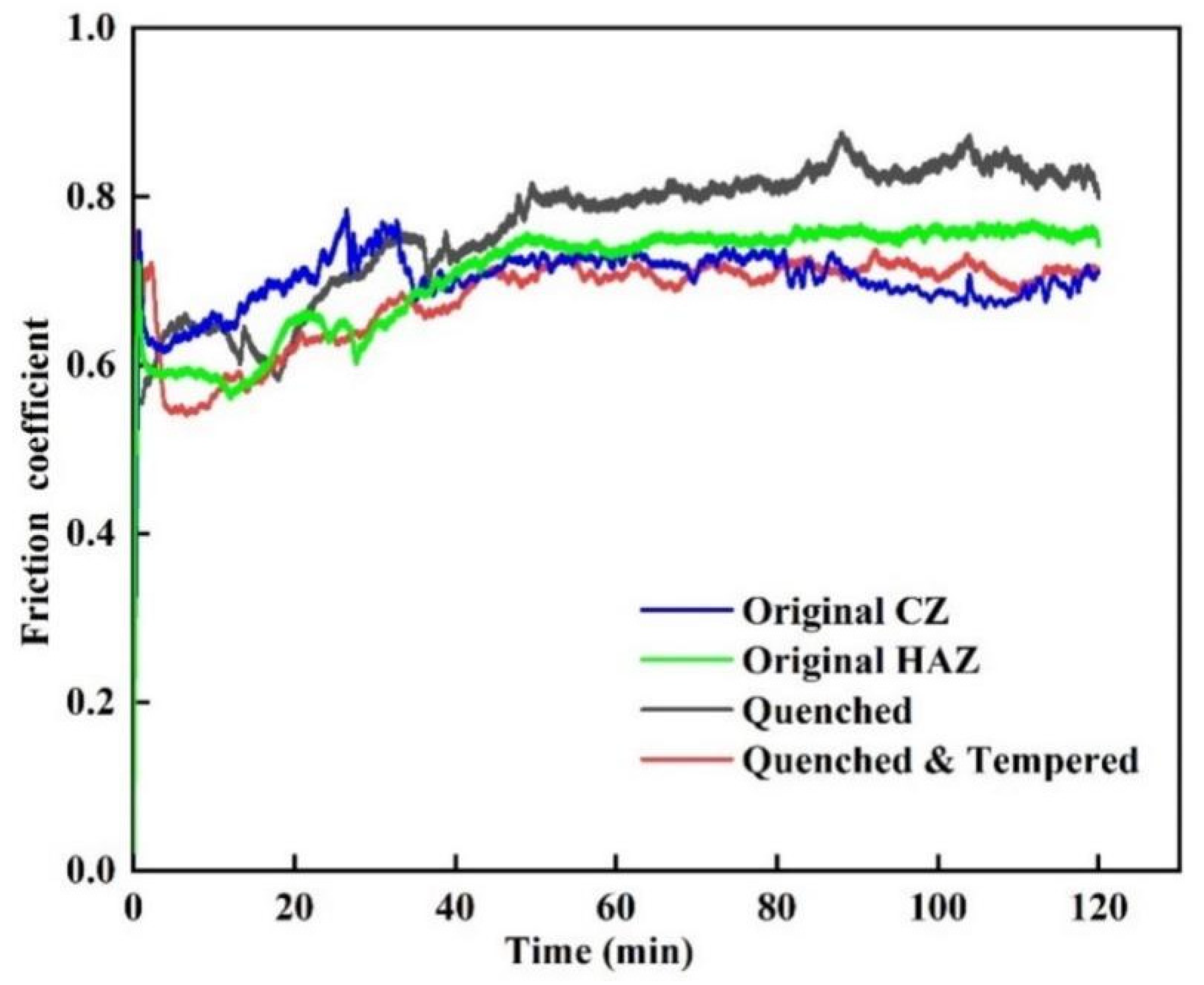
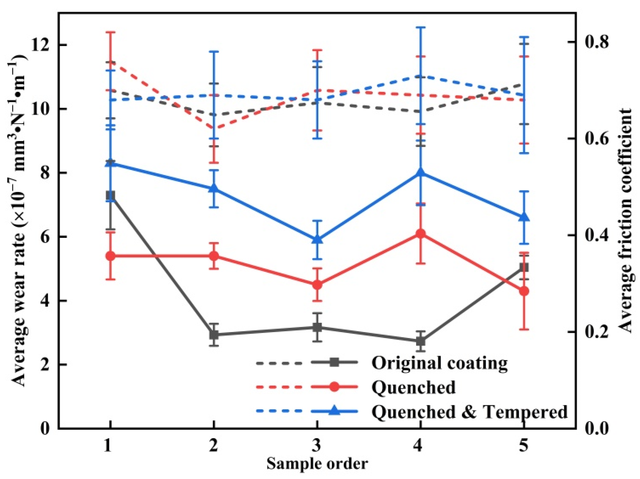
3.3. Wear Rate and Friction Coefficient

As seen from Figure 13, the cladding layer had experienced running in period and stable period during the wear process. The friction coefficients increased rapidly during the running-in period, which was accompanied with increased wear rate of T15 coatings. The friction coefficient tended to be stable from rising, falling and rising. The friction coefficients of the coatings varied from 0.5 to 0.8.
For original CZ, HAZ, quenched and quenched and tempered cladding layers, the average friction coefficients were 0.7, 0.71, 0.76 and 0.68, respectively, as shown in Figure 14. Post-heat treatment had no significant effect on the friction coefficient, because it was a comprehensive characteristic coefficient affected by many factors. The small friction coefficient of tempered samples did not mean that its wear rate was small [37]. The average wear rate of original CZ (7.3 × 10⁻⁷ mm3 × N−1 × m−1) was nearly twice that of HAZ. After the quenching and quenching–tempering process, the microstructures and hardness gradient of the cladding layer was uniform. The wear rate was 5.6 × 10⁻⁷ mm3 × N−1 × m−1 and 8.5 × 10⁻⁷ mm3 × N−1 × m−1 respectively.
Figure 15 showed the wear trace morphology of different cladding layers. As shown in Figure 15a, there were a large number of fatigue cracks, spalling and furrows on the wear surface of original CZ for large residual stress and brittle phases. It indicated that the main wear mechanism was fatigue failure and abrasive wear [38]. Under the cyclic alternating load, microcracks appeared on surface, and then the residual stress promoted the propagation of microcracks into macrocracks [39]. After quenching and quenching–tempering, the wear mark surface of the sample was relatively smooth. This was due to the hardness improving and the residual stress reducing, avoiding the initiation and rapid propagation of microcracks [40]. In addition, the number of fatigue cracks and the fatigue shedding phenomenon was significantly reduced, as shown in Figure 15b,c. The results showed that the wear mechanism was still mainly slight-abrasive wear and fatigue wear.
Compared with quenched and tempered samples, there were many fatigue cracks in the wear marks of quenched samples, because there were a lot of brittle martensite and residual stress on the surface. The plasticity and strength of tempered coating was improved for a lot of dispersed carbides. Due to the low surface hardness of the tempered sample, deep furrows were formed under the action of hard wear debris.
As seen from Figure 16, the average friction coefficient of coatings with different parameters hovered around 0.7. For different coatings, the standard deviation of the average wear rate was 0.21 mm3 × N−1 × m−1. After quenching (1100 °C) and quenching–tempering (1100 °C–540 °C), it was reduced to 0.07 and 0.09 mm3 × N−1 × m−1, respectively. According to the wear data of the above coating with different parameters, the experimental accuracy was verified by the same post-heat treatment process.

4. Conclusions

There were obvious “black-and-white” areas (cladding zone and heat-affected zone) on the surface of the T15 cladding layer. The average size of equiaxed grains was finer. The microhardness was about 200 HV higher in the CZ than HAZ. The average wear rate of original CZ and HAZ was 7.3 × 10⁻⁷ mm3·N−1·m−1 and 4.3 × 10⁻⁷ mm3·N−1·m−1. The alloy compounds were distributed in the grain boundaries for both regions. The microstructure uniformity and hardness gradient of the surface was eliminated by the post-heat treatment. The alloy elements except for V were dissolved into grains during the quenching process.
The microhardness of cladding layers was 910 HV after quenching and 750 HV after tempering. Post-heat treatment had no significant effect on the friction coefficient. After quenching and quenching–tempering, the wear rate of sample 1 was 5.6 × 10⁻⁷ mm3·N−1·m−1 and 8.5 × 10⁻⁷ mm3·N−1·m−1, respectively. The wear mechanism of the cladding layer was mainly abrasive wear and fatigue wear. The quenching residual stress could be eliminated by the subsequent tempering process.
For the cladding layers with different cladding process parameters, the average friction coefficient of coatings hovered around 0.7. In addition, the standard deviation of wear rate was decreased after post-heat treatment.

Author Contributions

All of the authors contributed to this idea and method. Sample preparation, data acquisition, and analysis were all performed by Y.M. The first draft of the manuscript was written by Y.M. Corresponding author, Y.Z., read the comments on the previous version of the manuscript and approved the revised manuscript. All authors have read and agreed to the published version of the manuscript.

Funding

This work was financially supported by the National Natural Science Foundation of China (No. 51905148 and No. 51875169) and by the Fundamental Research Funds for the Central Universities (No. B200202218).

Data Availability Statement

All data that support the findings of this study are available from the corresponding author upon reasonable request.

Conflicts of Interest

The authors declare no conflict of interest. The funders had no role in the design of the study, in the collection, analyses, or interpretation of data, in the writing of the manuscript, or in the decision to publish the results.

References

  1. Zhao, F.S.; Zhang, Z.H.; Shao, M.H.; Bi, Y.J.; Zhao, Y.Q.; Wang, Z.W.; Li, Y.; Li, H.H.; Xu, X.G.; He, Y.Y. Mechanical and Wear Properties of 42CrMo Steel by Plasma Nitriding assisted Hollow Cathode Ion Source. Mat. Res. 2021, 24, 1–10. [Google Scholar] [CrossRef]
  2. Zhu, L.J.; Liu, Y.H.; Li, Z.W.; Zhou, L.; Li, Y.J.; Xiong, A.H. Microstructure and properties of Cu-Ti-Ni composite coatings on gray cast iron fabricated by laser cladding. Opt. Laser Technol. 2020, 122, 105879. [Google Scholar] [CrossRef]
  3. Karmakar, D.P.; Muvvala, G.; Nath, A.K. Effect of scan strategy and heat input on the shear strength of laser cladded Stellite 21 layers on AISI H13 tool steel in as-Deposited and heat treated conditions. Surf. Coat. Technol. 2020, 384, 125331. [Google Scholar] [CrossRef]
  4. Das, A.K. Effect of rare earth oxide additive in coating deposited by laser cladding: A review. Mater. Today Proc. 2022, 52, 1558–1564. [Google Scholar] [CrossRef]
  5. Liu, J.S.; Shi, Y. Microstructure and wear behavior of laser-Cladded Ni-Based coatings decorated by graphite particles. Surf. Coat. Technol. 2021, 412, 127044. [Google Scholar] [CrossRef]
  6. Zhang, Z.; Yu, T.; Kovacevic, R. Erosion and Corrosion Resistance of Laser Cladded AISI 420 Stainless Steel Reinforced with VC. Appl. Surf. Sci. 2017, 410, 225–240. [Google Scholar] [CrossRef]
  7. He, B.; Zhang, L.J.; Zhu, Q.H.; Wang, J.; Yun, X.; Luo, J.S.; Chen, Z.K. Effect of solution treated 316L layer fabricated by laser cladding on wear and corrosive wear resistance. Opt. Laser Technol. 2020, 121, 105788. [Google Scholar] [CrossRef]
  8. Feng, Y.L.; Yao, C.W.; Shen, C.; Feng, Y.Q.; Feng, K.; Li, Z.G. Influence of in-Situ synthesized carboborites on microstructure evolution and the wear resistance of laser clad Fe-Base composite coatings. Mater. Charact. 2020, 164, 110326. [Google Scholar] [CrossRef]
  9. Hou, Q.Y. Influence of molybdenum on the microstructure and properties of a FeCrBSi alloy coating deposited by plasma transferred arc hard facing. Surf. Coat. Technol. 2013, 225, 11–20. [Google Scholar] [CrossRef]
  10. Han, B.; Li, M.Y.; Wang, Y. Microstructure and wear resistance of laser clad Fe−Cr3C2 composite coating on 35CrMo steel. Mater. Eng. Perform. 2013, 22, 3749–3754. [Google Scholar] [CrossRef]
  11. Qi, K.; Yang, Y.; Hu, G.F.; Lu, X.; Li, J.D. Thermal expansion control of composite coatings on 42CrMo by laser Cladding. Surf. Coat. Technol. 2020, 397, 125983. [Google Scholar] [CrossRef]
  12. Saeedi, R.; Razavi, R.S.; Bakhshi, S.R.; Erfanmanesh, M.; Bani, A.A. Optimization and characterization of laser cladding of NiCr and NiCr–TiC composite coatings on AISI 420 stainless steel. Ceram. Int. 2021, 47, 4097–4110. [Google Scholar] [CrossRef]
  13. Monkova, K.; Monka, P.; Jakubeczyova, D. The Research of the High Speed Steels Produced by Powder and Casting Metallurgy from the View of Tool Cutting Life. Appl. Mech. Mater. 2013, 302, 269–274. [Google Scholar] [CrossRef]
  14. Alouane, C.; Kasser, A. Consolidation by atmospheric pressure of T15 tool steel powder. Powder Technol. 2019, 352, 331–339. [Google Scholar] [CrossRef]
  15. Morozow, D.; Siemiatkowski, Z.; Gevorkyan, E.; Ruckiet, M.; Matijošius, J.; Kilikevicius, A.; Caban, J.; Krzysiak, Z. Effect of Yttrium and Rhenium Ion Implantation on the Performance of Nitride Ceramic Cutting Tools. Materials 2020, 13, 4687. [Google Scholar] [CrossRef]
  16. Zhang, G.Q.; Yuan, H.; Jiao, D.L.; Li, Z.; Zhang, Y.; Liu, Z.W. Microstructure evolution and mechanical properties of T15 high speed steel prepared by twin-Atomiser spray forming and thermo-Mechanical processing. Met. Mater. Int. 2012, 558, 566–571. [Google Scholar] [CrossRef]
  17. Han, X.; Li, C.; Yang, Y.P.; Gao, X.; Gao, H.X. Experimental research on the influence of ultrasonic vibrations on the laser cladding process of a disc laser. Surf. Coat. Technol. 2021, 406, 126750. [Google Scholar] [CrossRef]
  18. Nyadongo, S.T.; Olakanmi, E.O.; Pityana, S.L. Experimental and numerical analyses of geometrical and microstructural features of Tribaloy T-800 composite coating deposited via laser cladding-Assisted with pre-Heat (LCAP) process. J. Manuf. Process. 2021, 69, 84–111. [Google Scholar] [CrossRef]
  19. Li, W.Y.; Yang, X.F.; Xiao, J.P.; Hou, Q.M. Effect of WC mass fraction on the microstructure and friction properties of WC/Ni60 laser cladding layer of brake discs. Ceram. Int. 2021, 47, 28754–28763. [Google Scholar] [CrossRef]
  20. Jiao, X.Y.; Wang, C.M.; Gong, Z.Q.; Wang, G.M.; Sun, H.F.; Yang, H.R. Effect of Ti on T15M composite coating fabricated by laser cladding technology. Surf. Coat. Technol. 2017, 325, 643–649. [Google Scholar] [CrossRef]
  21. Szala, M.; Latka, L.; Walczak, M.; Winnicki, M. Comparative Study on the Cavitation Erosion and Sliding Wear of Cold-Sprayed Al/Al2O3 and Cu/Al2O3 Coatings, and Stainless Steel, Aluminium Alloy, Copper and Brass. Metals 2020, 10, 856. [Google Scholar] [CrossRef]
  22. Lv, H.; Li, Z.J.; Li, X.D.; Yang, K.; Li, F.; Xie, H.L. Effect of Vanadium Content on the Microstructure and Mechanical Properties of IN718 Alloy by Laser Cladding. Materials 2021, 14, 2362. [Google Scholar] [CrossRef] [PubMed]
  23. Morozow, D.; Barlak, M.; Werner, Z.; Pisarek, M.; Konarski, P.; Zagorski, J.; Rucki, M.; Chalko, L.; Lagodzinski, M.; Narojczyk, J.; et al. Wear Resistance Improvement of Cemented Tungsten Carbide Deep-Hole Drills after Ion Implantation. Materials 2021, 14, 239. [Google Scholar] [CrossRef] [PubMed]
  24. Diniz, A.E.; Machado, A.R.; Correa, J.G. Tool wear mechanisms in the machining of steels and stainless steels. Int. J. Adv. Manuf. Technol. 2016, 87, 3157–3168. [Google Scholar] [CrossRef]
  25. Ben, Q.; Zhang, Y.; Sun, L.; Wang, L.; Wang, Y.; Zhan, X. Wear and Corrosion Resistance of FeCoCrxNiAl High-Entropy Alloy Coatings Fabricated by Laser Cladding on Q345 Welded Joint. Metals 2022, 12, 1428. [Google Scholar] [CrossRef]
  26. Wang, Y.Y.; Shi, H.; Hao, X.H.; Liu, H.X.; Zhang, X.W. Microstructure and Wear Resistance of Fe60 Laser Cladding Coating Assisted by Steady Magnetic Field–Mechanical Vibration Coupling Field. Coatings 2022, 12, 751. [Google Scholar] [CrossRef]
  27. Wang, X.Y.; Liu, Z.D.; Li, J.Y.; Chen, L.; Li, B.K. Effect of heat treatment on microstructure, corrosion resistance, and interfacial characteristics of Inconel 625 laser cladding layer. Optik 2022, 270, 169930. [Google Scholar] [CrossRef]
  28. Cai, Y.C.; Shan, M.D.; Manladan, S.M.; Zhu, L.S.; Gao, F.F.; Sun, D.; Han, J. Effect of high temperature heat treatment on microstructure and properties of FeCoCrNiAl high-Entropy alloy laser cladding layer. Mater. Charact. 2022, 191, 112137. [Google Scholar] [CrossRef]
  29. Song, M.J.; Wu, L.S.; Liu, J.M.; Hu, Y. Effects of laser cladding on crack resistance improvement for aluminum alloy used in aircraft skin. Opt. Laser. Technol. 2021, 133, 106531. [Google Scholar] [CrossRef]
  30. Zhang, Y.T.; Ma, Y.L.; Wang, G.; Ji, X.L.; Li, Z.C. Experimental Study on the Wear Properties of 42CrMo Steel with Different Microstructures and T15 Laser Cladding. J. Mater. Eng. Perform. 2022, 31, 4232–4241. [Google Scholar]
  31. Shan, B.; Chen, J.L.; Chen, S.Y.; Ma, M.Z.; Ni, L.L.; Shang, F.M.; Zhou, L. Laser cladding of Fe-Based corrosion and wear-resistant alloy: Genetic design, microstructure, and properties. Surf. Coat. Technol. 2022, 433, 128117. [Google Scholar] [CrossRef]
  32. Joseph, G.B.; Valarmathi, T.N.; Rajan, J.A. Effect of welding parameters on mechanical and corrosion behavior of Stellite 6 cladded SA387 Gr 91 with ERNiCr-3 buffer layer. T. Can. Soc. Mech. Eng. 2020, 45, 37–47. [Google Scholar] [CrossRef]
  33. Craig, P.; Ramandi, H.L.; Chen, H.H.; Vandermaat, D.; Crosky, A.; Hagan, P.; Hebblewhite, B.; Saydam, S. Stress corrosion cracking of rockbolts: An in-situ testing approach. Constr. Build. Mater. 2021, 269, 121275. [Google Scholar] [CrossRef]
  34. Li, Y.J.; Dong, S.Y.; Yan, S.X.; Li, E.Z.; Liu, X.T.; He, P.; Xu, B.S. Deep pit repairing of nodular cast iron by laser cladding NiCu/Fe-36Ni low-Expansion composite alloy. Mater. Charact. 2019, 151, 273–279. [Google Scholar] [CrossRef]
  35. Jiao, X.Y.; Wang, J.; Wang, C.M.; Gong, Z.Q.; Pang, X.X.; Xiong, S.M. Effect of laser scanning speed on microstructure and wear properties of T15M cladding coating fabricated by laser cladding technology. Opt. Lasers Eng. 2018, 110, 163–171. [Google Scholar] [CrossRef]
  36. Gong, F.B.; Shen, J.; Gao, R.H.; Zhang, T.; Xie, X.; Li, Y. Influence of heat treatment on microstructure and mechanical properties of FeCrNi coating produced by laser cladding. T. Nonferr. Metal. Soc. 2016, 26, 2117–2125. [Google Scholar] [CrossRef]
  37. Zhang, L.; Bai, Y.; He, T.; Fan, W.; Ma, Y.S.; Liu, H.B.; Wang, Y.; Chang, Z.D.; Kang, Y.X. Performance of plasma-Sprayed thermal barrier coating with engineered unmelted nano-Particle contents. Surf. Coat. Technol. 2019, 368, 67–78. [Google Scholar] [CrossRef]
  38. Ning, K.; Wang, J.M.; Shi, M.J.; Ning, W.G.; Zhang, F. Friction-Increasing Mechanism of Contact Pair Using Different Surface Treatment Processes. Tribol. Int. 2022, 165, 107337. [Google Scholar] [CrossRef]
  39. Salvati, E. Residual stress as a fracture toughening mechanism: A Phase-Field study on a brittle material. Theor. Appl. Fract. Mech. 2021, 114, 103021. [Google Scholar] [CrossRef]
  40. Wang, D.S.; Liang, E.J.; Chao, M.J.; Yuan, B. Investigation on the microstructure and cracking susceptibility of laser-Clad V2O5 /NiCrBSiC alloy coatings. Surf. Coat. Technol. 2008, 202, 1371–1378. [Google Scholar] [CrossRef]
Figure 1. Micromorphology of T15 powder.
Lubricants 10 00271 g001
Figure 2. Heat treatment process curve of cladding layer.
Lubricants 10 00271 g002
Figure 3. Schematic diagram of the wear test.
Lubricants 10 00271 g003
Figure 4. Schematic diagram of the wear mark: (a) sample wear scar, (b) wear mark section. (l is the length of wear scar, w is the width of wear scar, h is the depth of wear scar, s is the cross sectional area of wear scar, R is the Grinding ball radius).
Lubricants 10 00271 g004
Figure 5. Surface macro morphology, microstructure and hardness of cladding layer: (a) macro morphology, (b) hardness gradient, (c) position 1, (d) position 2.
Lubricants 10 00271 g005
Figure 6. The EDS mapping results of T15 coating at different areas: (a) position 1, (b) position 2.
Lubricants 10 00271 g006
Figure 7. Schematic diagram of multi-channel transverse overlapping.
Lubricants 10 00271 g007
Figure 8. Surface macro morphology of cladding layer at different quenching temperatures: (a) original coating, (b) 1100 °C, (c) 1190 °C, (d) 1240 °C.
Lubricants 10 00271 g008
Figure 9. The microstructure of the cladding layer after heat treatment: (a) quenched, (b) quenched-tempered.
Lubricants 10 00271 g009
Figure 10. EDS area scanning results of the cladding layer after heat treatment: (a) quenched, (b) quenched–tempered.
Lubricants 10 00271 g010
Figure 11. XRD patterns of the T15 coating.
Lubricants 10 00271 g011
Figure 12. Surface microhardness of cladding layer.
Lubricants 10 00271 g012
Figure 13. Friction coefficient of cladding layer.
Lubricants 10 00271 g013
Figure 14. Average wear rate and friction coefficient of cladding layers.
Lubricants 10 00271 g014
Figure 15. The SEM wear trace morphology of cladding layer: (a) original CZ, (b) quenched, (c) quenched–tempered.
Lubricants 10 00271 g015
Figure 16. Average wear rate and friction coefficient of coatings with different parameters.
Lubricants 10 00271 g016
Table 1. Chemical composition of 42CrMo and T15 powder (wt. %).
CCoCrMoMnSiWVFe
42CrMo0.420.990.190.630.21Bal.
T151.65.44.50.450.4811.74.7Bal.
Table 2. Laser cladding process parameters.
OrderPower
(W)
Powder Feeding
Voltage (V)
Scanning Speed
(mm/s)
Overlap Rate
1200050730%
2230040640%
3230050840%
4230060940%
5230070640%
Table 3. Details of the wear test conditions.
Load (N)Speed (r/min) Test
Duration (min)
Sliding Distance (m)Reciprocating Length (mm)
501001201205
Table 4. Average wear rate of coatings at different heat treatment processes.
Heat Treatment ProcessAverage Wear Rate (×10−6 mm3·N−1·m−1)
Original coating0.73
Quenched (1100 °C)0.54
Quenched (1190 °C)1.2
Quenched (1240 °C)1.34
Publisher’s Note: MDPI stays neutral with regard to jurisdictional claims in published maps and institutional affiliations.

