Monitoring the Conditions of Hydraulic Oil with Integrated Oil Sensors in Construction Equipment


Abstract
:
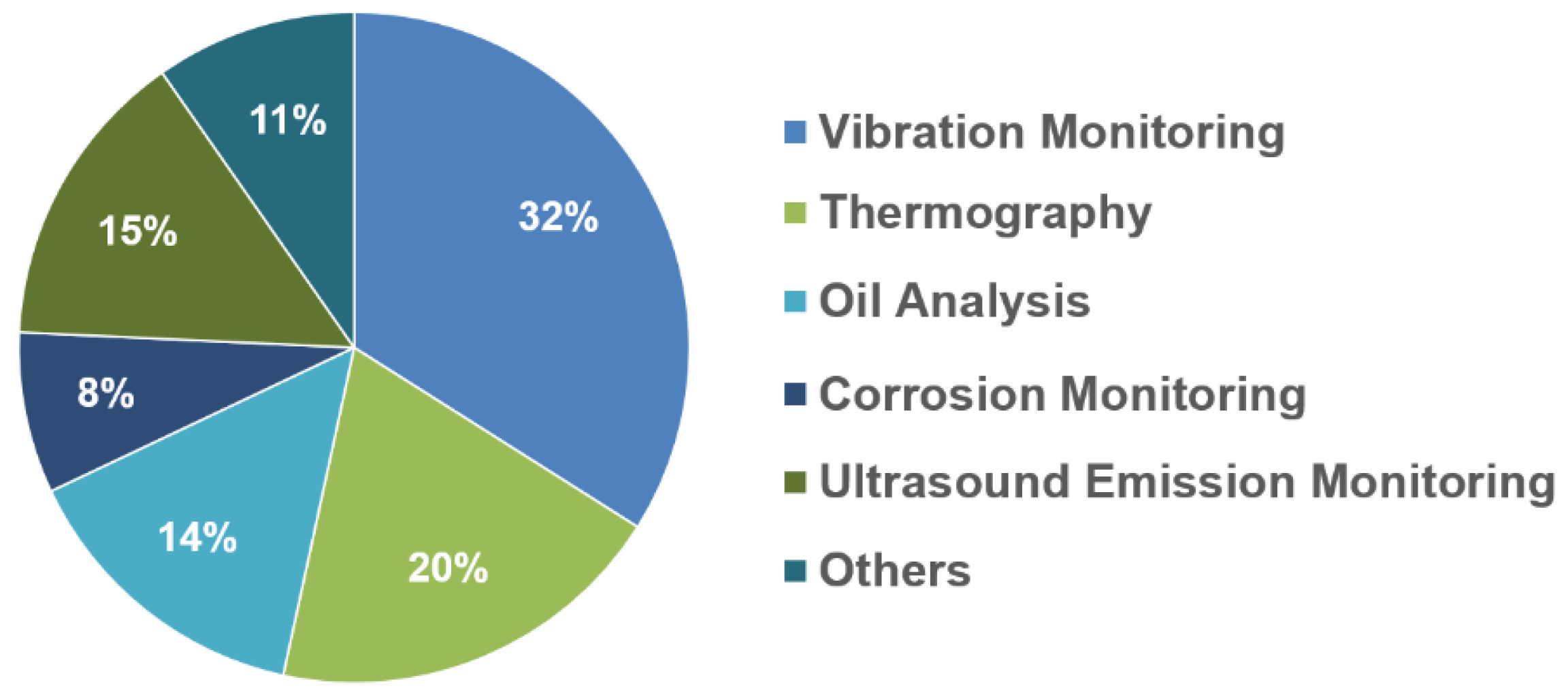
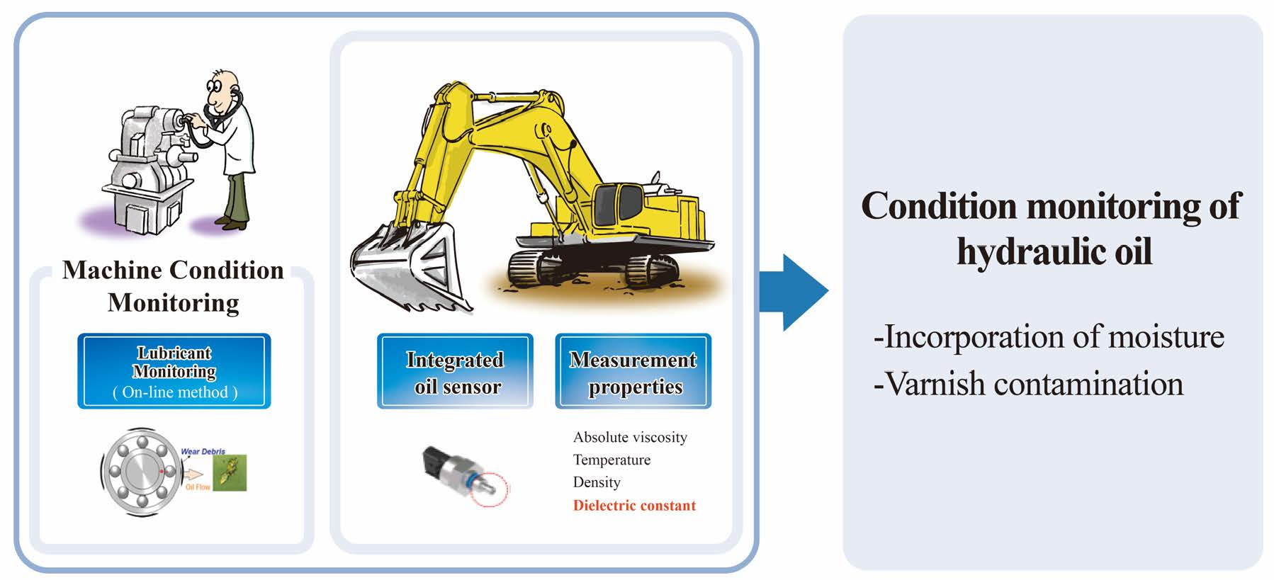
1. Introduction
2. Integrated Oil Sensor and Experimental Device
3. Results
3.1. Test on Uncontaminated Oil
3.2. Influence of Incorporation of Dust and Improper Lubricant
3.3. Influence of Incorporation of Moisture
3.4. Influence of Varnish
4. Conclusions
Author Contributions
Data Availability Statement
Acknowledgments
Conflicts of Interest
Nomenclature
| AV | Absolute viscosity (cP) |
| Co | Capacitance in a vacuum |
| C’ | Capacitance of a material (lubricant) |
| DC | Dielectric constant of fluid |
| E | Electric field |
| L | Avogadro Number (6.02 × 10²³ molecules of oil /mole) |
| MW | Molecular weight (g/mole) |
| T | Temperature in degrees Celsius (°C) |
| T1 | Temperature Kelvin |
| k | Boltzmann constant (1.31 × 10⁻²³ joules/degree Kelvin) |
| α | Polarizability |
| ε | Permittivity |
| εo | Permittivity in a vacuum |
| εm | Permittivity of a material(lubricant) |
| μ1 | Dipole moment |
| ρ | Density of fluid (g/m3) |
References
- Waris, M.; Shahir Liew, M.; Faris Khamidi, M.; Idrus, A. Criteria for the selection of sustainable on site construction equipment. Int. J. Sustain. Built Environ. 2014, 3, 96–110. [Google Scholar] [CrossRef] [Green Version]
- Naskoudakis, I.; Petroutsatou, K. A thermatic review of main researches on construction equipment over the recent years. Procedia Eng. 2016, 164, 206–213. [Google Scholar] [CrossRef]
- Mishra, A.K.; Aryal, B. Operational maintenance analysis of actively utilized road construction equipments. Mater. Today Proc. 2021, in press. [Google Scholar] [CrossRef]
- Premjith, S.P.; Monisha, M. Analysis of equipment maintenance operation and repair in a construction industry. Int. J. Eng. Manag. Res. 2017, 7, 18–23. [Google Scholar]
- Hong, S.H. Literature review of machine condition monitoring with oil sensors—Types of Sensors and their functions. Tribol. Lubr. 2020, 36, 297–306. [Google Scholar]
- Kumar, M.; Mukherjee, P.S.; Misra, N.M. Advancement and current status of wear debris analysis for machine condition monitoring: A review. Ind. Lubr. Tribol. 2013, 65, 3–11. [Google Scholar] [CrossRef]
- Younus, A.M.D.; Yang, B.S. Intelligent fault diagnosis of rotating machinery using infrared thermal image. Expert Syst. Appl. 2012, 39, 2082–2091. [Google Scholar] [CrossRef]
- Hong, S.H. Machine Condition Diagnosis Based on Oil Analysis—Fundamental Course, 1st ed.; Hanteemedia: Seoul, Korea, 2021; pp. 94–96. [Google Scholar]
- Global Machine Condition Monitoring Market Size, Share & Industry Trends Analysis Report by Offering. Available online: https://www.kbvresearch.com/machine-condition-monitoring-market (accessed on 20 July 2022).
- Markova, L.V.; Makarenko, V.M.; Semenyuk, M.S.; Zozulya, A.P. On-line monitoring of the viscosity of lubricating oils. J. Frict. Wear 2010, 31, 433–442. [Google Scholar] [CrossRef]
- Markova, L.V.; Myshkin, N.K.; Kong, H.; Han, H.G. On-line acoustic viscometry in oil condition monitoring. Tribol. Int. 2011, 44, 963–970. [Google Scholar] [CrossRef]
- Saluja, A.; Kalonia, D.S. Measurement of fluid viscosity at microliter volumes using quartz impedance analysis. AAPS PharmSciTech 2004, 5, e47. [Google Scholar] [CrossRef]
- Salzer, S.; Jahns, R.; Piorra, A.; Teliban, I.; Reermann, J.; Höft, M.; Quandt, E.; Knöchel, R. Tuning fork for noise suppression in magnetolectric sensors. Sens. Actuators A Phys. 2016, 237, 91–95. [Google Scholar] [CrossRef]
- Heinisch, M.; Voglhuber-Brunnmaier, T.; Reichel, E.K.; Dufour, I.; Jakoby, B. Application of resonant steel tuning forks with circular and rectangular cross sections for precise mass density and viscosity measurements. Sens. Actuators A Phys. 2015, 226, 163–174. [Google Scholar] [CrossRef]
- García-Arribas, A.; Gutiérrez, J.; Kurlyandskaya, G.V.; Barandiarán, J.M.; Svalov, A.; Fernández, E.; Lasheras, A.; De Cos, D.; Bravo-Imaz, I. Sensor applications pf soft magnetic materials based on magneto-impedance, magneto-elastic resonance and magneto-electricity. Sensors 2014, 14, 7602–7624. [Google Scholar] [CrossRef] [Green Version]
- Zhu, X.; Zhong, C.; Zhe, J. Lubricating oil condition sensors for online machine health monitoring—A review. Tribol. Int. 2017, 109, 473–484. [Google Scholar] [CrossRef] [Green Version]
- Du, L.; Zhe, J.; Carletta, J.; Veillette, R.; Choy, F. Real-time monitoring of wear debris in lubricating oil using a microfluidic inductive coulter counting device. Microfluid. Nanofluid. 2010, 9, 1241–1245. [Google Scholar] [CrossRef]
- Gastops Long Live Equipment. MetalSCAN MS4000. Available online: http://www.gastops.com/wpcontent/uploads/2016/09/C008850_001.pdf (accessed on 16 December 2020).
- Du, L.; Zhe, J. A high throughput inductive pulse sensor for online oil debris monitoring. Tribol. Int. 2011, 44, 175–179. [Google Scholar] [CrossRef]
- Du, L.; Zhe, J. Parallel sensing of metallic wear debris in lubricants using under-sampling data processing. Tribol. Int. 2012, 53, 28–34. [Google Scholar] [CrossRef]
- Du, L.; Zhu, X.; Han, Y.; Zhao, L.; Zhe, J. Improving sensitivity of an inductive pulse sensor for detection of metallic wear debris in lubricants using parallel LC resonance method. Meas. Sci. Technol. 2013, 24, 75106. [Google Scholar] [CrossRef]
- Wang, C.; Bai, C.; Yang, Z.; Zhang, H.; Li, W.; Wang, X.; Zheng, Y.; Ilerioluwa, L.; Sun, Y. Research on High Sensitivity Oil Debris Detection Sensor Using High Magnetic Permeability Material and Coil Mutual Inductance. Sensors 2022, 22, 1833. [Google Scholar] [CrossRef]
- Wu, Z.; Liu, Z.; Yuan, H.; Yu, K.; Gao, Y.; Liu, L.; Pan, X. Multichannel inductive sensor based on phase division multiplexing for wear debris detection. Micromachines 2019, 10, 246. [Google Scholar] [CrossRef] [Green Version]
- Wang, Y.; Lin, T.; Wu, D.; Zhu, L.; Qing, X.; Xue, W. A new in situ coaxial capacitive sensor network for debris monitoring of lubricating oil. Sensors 2022, 22, 1777. [Google Scholar] [CrossRef] [PubMed]
- Xu, C.; Zhang, P.; Wang, H.; Li, Y.; Lv, C. Ultrasonic echo wave shape features extraction based on QPSO-matching pursuit for online wear debris discrimination. Mech. Syst. Signal Process. 2015, 60, 301–315. [Google Scholar] [CrossRef]
- Du, L.; Zhe, J. An integrated ultrasonic-inductive pulse sensor for wear debris detection. Smart Mater. Struct. 2013, 22, 25003. [Google Scholar] [CrossRef]
- Hamilton, A.; Cleary, A.; Quail, F. Development of a novel wear detection system for wind turbine gearboxes. IEEE Sens. J. 2014, 14, 465–473. [Google Scholar] [CrossRef]
- Wu, T.; Wu, H.; Du, Y.; Kwok, N.; Peng, Z. Imaged wear debris separation for on-line monitoring using gray level and integrated morphological features. Wear 2014, 316, 19–29. [Google Scholar] [CrossRef]
- Liu, Z.; Liu, Y.; Zuo, H.; Wang, H.; Chen, Z. An oil wear particles inline optical sensor based on motion characteristics for rotating machines condition monitoring. Machines 2022, 10, 727. [Google Scholar] [CrossRef]
- Holzki, M.; Fouckhardt, H.; Klotzbucher, T. Evanescent-field fiber sensor for the water content in lubricant oils with sensitivity increase by dielectrophoresis. Sens. Actuators A Phys. 2012, 184, 93–97. [Google Scholar] [CrossRef]
- Smiechowski, M.F.; Lvovich, V.F. Iridium oxide sensors for acidity and basicity detection in industrial lubricants. Sens. Actuators B Chem. 2003, 96, 261–267. [Google Scholar] [CrossRef]
- Soleimani, M.; Sophocleous, M.; Wang, L.; Atkinson, J.; Hosier, I.L.; Vaughan, A.S.; Taylor, R.I.; Wood, R.J.K. Base oil oxidation detection using novel chemical sensors and impedance spectroscopy measurements. Sensors Actuators B Chem. 2014, 199, 247–258. [Google Scholar] [CrossRef] [Green Version]
- Kimura, Y.; Kato, N.; Kataoka, T.; Takajashi, K.; Kikuchi, T. Bubble behavior in engine lubricant. Int. J. Automot. Eng. 2011, 2, 149–153. [Google Scholar] [CrossRef] [Green Version]
- Zhu, J.; Eric, B.; David, H. Survey of lubrication oil condition monitoring, diagnostics, prognostics techniques and systems. J. Chem. Sci. Technol. 2013, 3, 100–115. [Google Scholar]
- John, D. A novel approach to predictive maintenance: A portable multicomponent MEMS sensor for on-line monitoring of fluid condition in hydraulic and lubricating systems. Tribol. Trans. 2006, 49, 545–553. [Google Scholar]
- Kobayashi, S.; Kondoh, J. Properties of engine oil measured using a surface acoustic wave sensor. Jpn. J. Appl. Phys. 2018, 57, 07LD09. [Google Scholar] [CrossRef]
- Podunavac, I.; Radonic, V.; Bengin, V.; Jankovic, N. Microwave spoof surface plasmon polariton-based sensor for ultrasensitive detection of liquid analyte dielectric constant. Sensors 2021, 21, 5477. [Google Scholar] [CrossRef] [PubMed]
- Esmaeili, K.; Wang, L.; Harvey, T.J.; White, N.M.; Holwager, W. Electrical discharges in oil-lubricated rolling contacts and their detection using electrostatic sensing technique. Sensors 2022, 22, 392. [Google Scholar] [CrossRef] [PubMed]
- Jiang, Y.; He, X. Overview of applications of the sensor technologies for construction machinery. IEEE Access 2020, 8, 110324–110335. [Google Scholar] [CrossRef]
- Singh, M.; Lathkar, G.S.; Basu, S.K. Failure prevention of hydraulic system based on oil contamination. J. Inst. Eng. 2012, 93, 269–274. [Google Scholar] [CrossRef]
- Ng, F.; Harding, J.A.; Glass, J. Improving hydraulic excavator performance through in line hydraulic oil contamination monitoring. Mech. Syst. Signal Process. 2017, 83, 176–193. [Google Scholar] [CrossRef] [Green Version]
- Zeng, J.; Zhao, C.; Zhang, M.; Zhao, M. Study condition monitoring of construction equipment based on wireless sensor networks. In Proceedings of the 2010 International Conference on Computer Application and System Modeling, Taiyuan, China, 22–24 October 2010. [Google Scholar]
- Marian, M.; Tremmel, S. Current trends and applications of machine learning in tribology—A review. Lubricants 2021, 9, 86. [Google Scholar] [CrossRef]
- Sun, H.; Liu, Y.; Tan, J. Research on testing method of oil characteristic based on quartz tuning fork sensor. Appl. Sci. 2021, 11, 5642. [Google Scholar] [CrossRef]
- Carey, A.A. The Dielectric Constant of Lubrication Oils. DTIC Document. Available online: https://apps.dtic.mil/sti/citations/ADA347479 (accessed on 12 July 2022).
- Nelson, S.O.; Trabelsi, S. Factors influencing the dielectric properties of agricultural and food products. J. Microw. Power Electromagn. Energy 2012, 46, 93–107. [Google Scholar] [CrossRef] [PubMed]
- Liu, M.; Qin, X.; Chen, Z.; Tang, L.; Borom, B.; Cao, N.; Barnes, D.; Cheng, K.; Chen, J.; Wang, T.; et al. Frying Oil Evaluation by a Portable Sensor Based on Dielectric Constant Measurement. Sensors 2019, 19, 5375. [Google Scholar] [CrossRef] [PubMed]
- Dielectric Constant and Oil Analysis. Available online: https://www.machinerylubrication.com/Read/226/dielectric-constant-oil-analysis (accessed on 12 July 2022).
- Sludge and Varnish in Turbine Systems. Available online: http://www.machinerylubrication.com/Read/874/sludge-varnish-turbine (accessed on 3 August 2022).


| Measurement Properties | Measurement Range | Accuracy |
|---|---|---|
| Absolute viscosity (cP) | 0.5~50 | ±2% |
| Temperature (°C) | −40~150 | ±0.1 °C |
| Density (g/cm3) | 0.65~1.5 | ±1% |
| Dielectric constant | 1.0~6.0 | ±1% |
| Density | Kinematic Viscosity (cSt) | Viscosity Index | Flash Point (°C) | Pour Point (°C) | |
|---|---|---|---|---|---|
| (g/L @15 °C) | @ 40 °C | @ 100 °C | |||
| 845.7 | 46.37 | 7.97 | 144 | 253 | −45 |
| Ingredients | % of Weight | Ingredients | % of Weight |
|---|---|---|---|
| SiO2 | 69.0~77.0 | CaO | 2.5~5.5 |
| Al2O3 | 8.0~14.0 | MgO | 1.0~2.0 |
| Fe2O3 | 4.0~7.0 | TiO2 | 0~1.0 |
| Na2O | 1.0~4.0 | K2O | 2.0~5.0 |
| Measurement Items | Unused Oil | Used Oil (4156 h) |
|---|---|---|
| Viscosity @ 40 ℃ (cSt) | 48.28 | 46.36 |
| Viscosity @ 100 ℃ (cSt) | 8.23 | 7.90 |
| Viscosity Index | 145.0 | 141.0 |
| Magnesium, Mg (ppm) | 0.9 | 0.3 |
| Calcium, Ca (ppm) | 74.5 | 67.6 |
| Phosphorus, P (ppm) | 463.2 | 400.0 |
| Zinc, Zn (ppm) | 725.8 | 566.3 |
| Silicon, Si (ppm) | 0.0 | 1.5 |
| Boron, B (ppm) | 0.0 | 0.1 |
| Sodium, Na (ppm) | 0.1 | 2.2 |
| Potassium, K (ppm) | 0.0 | 0.3 |
| Iron, Fe (ppm) | 0.1 | 32.2 |
| Lead, Pb (ppm) | 0.1 | 0.3 |
| Copper, Cu (ppm) | 0.0 | 3.8 |
| Tin, Sn (ppm) | 0.0 | 1.0 |
| Aluminum, Al (ppm) | 0.0 | 0.6 |
| Molybdenum, Mo (ppm) | 0.2 | 0.4 |
| Titanium, Ti (ppm) | 0.0 | 0.2 |
| Antimony, Sb (ppm) | 1.3 | 2.0 |
| Manganese, Mn (ppm) | 0.0 | 0.8 |
Publisher’s Note: MDPI stays neutral with regard to jurisdictional claims in published maps and institutional affiliations. |
© 2022 by the authors. Licensee MDPI, Basel, Switzerland. This article is an open access article distributed under the terms and conditions of the Creative Commons Attribution (CC BY) license (https://creativecommons.org/licenses/by/4.0/).
Share and Cite
Hong, S.-H.; Jeon, H.-G. Monitoring the Conditions of Hydraulic Oil with Integrated Oil Sensors in Construction Equipment. Lubricants 2022, 10, 278. https://doi.org/10.3390/lubricants10110278
Hong S-H, Jeon H-G. Monitoring the Conditions of Hydraulic Oil with Integrated Oil Sensors in Construction Equipment. Lubricants. 2022; 10(11):278. https://doi.org/10.3390/lubricants10110278
Chicago/Turabian StyleHong, Sung-Ho, and Hong-Gyu Jeon. 2022. "Monitoring the Conditions of Hydraulic Oil with Integrated Oil Sensors in Construction Equipment" Lubricants 10, no. 11: 278. https://doi.org/10.3390/lubricants10110278
APA StyleHong, S.-H., & Jeon, H.-G. (2022). Monitoring the Conditions of Hydraulic Oil with Integrated Oil Sensors in Construction Equipment. Lubricants, 10(11), 278. https://doi.org/10.3390/lubricants10110278