Abstract
During the drilling process, the sealing performance of the roller cone bits is severely challenged by the complex downhole environment and frequent vibrations. In this paper, a comprehensive thermal–fluid–solid–dynamic multi-field coupling numerical model of new-generation single energizer metal seals (SEMS2) is developed. The instantaneous sealing performance of SEMS2 is studied under periodic vibration, instantaneous shock, and random vibration. Time-domain and frequency-domain changes in the sealing parameters with environmental pressures and rotational speeds under different vibrations are analyzed and compared. The results show that the liquid film distribution and lubrication state on the sealing end faces change constantly as the drill bit vibrates, which in turn affects the sealing performance of the SEMS2. The instantaneous leak rate fluctuates alternately between positive and negative under the three kinds of vibrations, aggravating the tendency of lubricant oil leakage and drilling mud invasion. With increasing environmental pressure and rotational speed, the fluctuation amplitudes of the maximum temperature increase, leakage rate, and friction torque under random vibration and instantaneous shock are significantly larger than those under periodic vibration. Our model and results have important theoretical significance for improving the design system of metal seals for drill bits.
1. Introduction
In recent years, deep strata have become important exploration and production areas of global oil and gas resources [1,2]. Roller cone bits are widely used in exploiting oil and natural gas due to their high specific pressure, high adaptability, and low wear [3,4]. In actual drilling work, bearing failure has been found to be one of the main reasons for damage to the roller cone bits [5]. The bearing sealing system faces severe challenges in complex hard formations, high temperature and pressure, and frequent vibration; thus, the operational reliability of the bearing sealing system is critical to the drilling efficiency, cost, and service life of the roller cone bits.
Single energizer metal seals are one of the most commonly used bearing seal types in roller cone bits, with simple structure, good vibration resistance, and high wear resistance [6]. Compared with first-generation single energizer metal seals (SEMS), the new-generation single energizer metal seals (SEMS2) have seen improvements in the geometric shape of the rubber energizers, the jaw sealing surface, and the size of the end faces on the metal seals. SEMS2 bears the long-term action of the inner lubricating oil pressure, the outer drilling fluid pressure, and the high-temperature underground environment during the working process [7]. The metal sealing rings inevitably deform under high pressure and temperature. On the other hand, the roller cone bits break rock in the composite way of pressing and cutting. In addition to the periodic vibration caused by the rotation of the bits, the metal sealing system of roller cone bits may be subjected to instantaneous impact or random vibration due to the movement of drill strings, formation characteristics, drilling conditions, and other factors [8,9,10], as confirmed by actual measured data [11,12,13]. Under transient conditions at the bottom of the well, the continuously changing load acts on the metal sealing rings and the liquid film between the end faces fluctuates significantly with the axial vibration of the drill bits. This may result in the increased intrusion of drilling mud and wear of the sealing end faces, which substantially shortens the service life of the bearing sealing system in the drill bits. Therefore, it is crucial to study the instantaneous dynamic characteristics of SEMS2 in the roller cone bits under various vibrations.
The literature contains a great deal of research on the steady-state performance of the metal seals of roller cone bits. Because of the particularity of the high-pressure drilling environment, many researchers have studied the mechanical properties and sealing performance of metal sealing systems using finite element analysis (FEA). Zhang et al. [14] found that the sealing performance of metal seals could be significantly improved by changing the structure of supporting rubber rings and tanks through FEA. Zhou et al. [15] found that the metal rotor and stator play a leading role in the sealing performance of SEMS2 and that the auxiliary rubber rings are prone to uneven high compression. Zhang et al. [16,17] studied the mechanical properties and temperature distribution of metal seals under high pressure and carried out multi-objective optimization of metal seals with the objective functions of external contact pressure and leakage rate. In addition, the stable maintenance of the liquid film on the end faces is essential to ensuring the sealing performance of the metal seals. The lubrication state on the end faces and the deformation and temperature field of the metal seals interact with each other. Xiong and Salant [18,19] established axially symmetric and non-axially symmetric steady-state numerical models of SEMS, considered the roughness and deformation of the end faces, and analyzed the variation of liquid pressure, thickness, and temperature under different environmental pressures. Ma et al. [20] established a thermal–fluid–solid multi-field coupling model for SEMS2, studied the steady-state performance of the metal seals, and carried out multi-objective optimization with the leakage rate and friction as targets. Very few examples in the literature report the dynamic characteristics of the metal seals in roller cone bits. Based on the steady-state model, Xiong and Salant [21] established a transient numerical model for predicting the performance of SEMS without considering the deformation of end faces under mixed lubrication. Their results showed that the transient leak rate and contact stress of the metal seals are two orders of magnitude larger than the steady-state results. The above studies provide a basis for predicting the performance of metal seals and extending the service life of the bit-bearing system. However, the dynamic performance of metal seals under frequent vibration or disturbance has not been thoroughly studied. It is necessary to systematically analyze the transient sealing performance of the metal seals in the roller cone bit under the actual drilling vibrations.
In this paper, an axisymmetric thermal–fluid–solid–dynamic coupling numerical model of SEMS2 is established by comprehensively considering the multi-field relations of heat transfer, fluid, solid, and vibration. The instantaneous sealing parameters of SEMS2, such as interface temperature, leakage rate, and frictional torque, are studied under periodic vibration, instantaneous shock, and random vibration to explore the influences of external excitation on metal seals of roller cone bits. Thus, it can provide a theoretical basis for improving the drilling efficiency and working life of roller cone bits and reducing the costs of the drilling system.
2. Research Subject and Numerical Model
2.1. Research Subjects
The diagram of the new-generation single energizer metal seals (SEMS2) is shown in Figure 1. The main parameters of the SEMS2 are shown in Table 1 and Table 2. The SEMS2 consists of a rotor, stator, O-ring, and rubber backup ring. The rotor is mounted in the inner hole of the cone. The stator is elastically supported by the O-ring and backup ring installed on the claw journal. The end faces of the rotor and stator cooperate. The clearance between the end faces is filled with the sealing medium (lubricating oil). The media on the inner diameter side and the outer diameter of metal seals are lubricating oil and drilling mud, respectively. The pressure difference (Δp) between the inner and outer diameter of the metal seals is adjusted to a specific range by the pressure balance system [22].
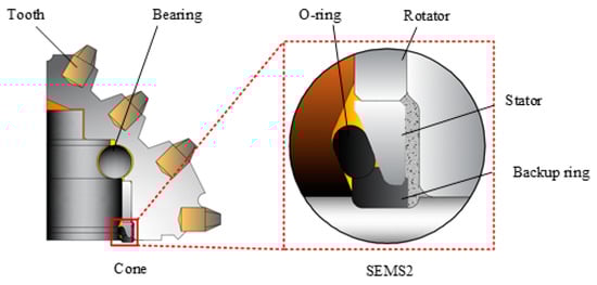
Figure 1.
Structure of roller cone bit and SEMS2 [6].

Table 1.
Main parameters of SEMS2.
Table 2.
Material and medium parameters of SEMS2.
The inner and outer pressures acting on the inclined surface of the sealing rings and the force of the O-ring and the backup ring acting on the lower part of the stator tend to make the sealing end faces close. The liquid film in the clearance between the rotor and stator is very thin, and the film thickness is the same micron level as the roughness of the sealing end faces. The liquid pressure (Fl) and asperity contact pressure (Fc) tend to make the sealing end faces open. In the steady state, the closing force (Fclose) is equal to the opening force (Fopen) between the end faces of the rotor and stator. However, the rotation of the drill bits is accompanied by complex vibrations. The metal sealing system is inevitably disturbed as a consequence. Under the excitation load, the lubrication state of the end faces and the liquid film pressure fluctuate accordingly, resulting in the unstable operation of the metal seals. Thus, the outer drilling mud can easily enter the bearing system through the sealing clearance, which causes severe wear and rapid failure.
2.2. Numerical Model
The interactions between the rotor, stator, liquid film on the end faces, and auxiliary seals all need to be considered in combination with fluid mechanics, solid mechanics, heat transfer, and dynamics. The thermal–fluid–solid–dynamic coupling relationship of SEMS2 is shown in Figure 2.
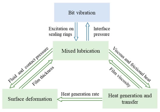
Figure 2.
Thermal–fluid–solid–dynamic coupling relationship.
The multi-field coupling numerical model of SEMS2 is established based on the fluid lubrication equations, heat transfer and contact mechanics analysis, and dynamic model. The particular simplifying assumptions are adopted as follows:
- The sealing system is two-dimensional axisymmetric;
- The sealing medium between the end faces is a Newtonian fluid;
- The influences of thermal hysteresis and inertial force are negligible;
- The coefficient of convective heat transfer does not change with time.
2.2.1. Lubrication Analysis
Considering the surface roughness and squeeze effect in the sealing clearance, the Reynolds equation in polar coordinates is [23,24]
where r is the radius coordinate, pl is the liquid film pressure, h is the film thickness, μ is the kinematic viscosity of the liquid film, φr is the radial flow factor (which is determined by the ratio of the film thickness h and comprehensive RMS roughness σ [25]), φc is the contact factor [26], and t is the time.
The liquid film pressure (pl) at each node is calculated, and the total liquid film force (Fl) on the sealing end faces is obtained as
where ri and ro are the inner and outer diameter of the sealing faces, respectively.
Due to the thin liquid film in the clearance, the micro-asperities on the end faces of the rotor and stator inevitably contact each other. The sealing zone of metal seals is often in a mixed lubrication state. The asperity distribution on the end faces is assumed to be Gaussian. The contact force (Fc) between the rotor and stator can be calculated using the plastic contact model, expressed as
where H is the yield strength of the sealing material, Am is the actual contact area, σ is the equivalent standard deviation of the surface roughness, and z is the asperity height.
The liquid film force (Fl) and the contact force (Fc) constitute the opening force (Fopen) between the sealing rings.
2.2.2. Heat Transfer Analysis
Under the action of viscous shear of liquid film and contact friction of micro-asperities, the heat flux q is generated between the end faces of the metal rings [27], expressed as
where ω is the angular velocity of the rotor, f0 is the friction coefficient, and pc is the contact pressure on the end faces.
The interface temperature can be solved by the influence coefficient method according to the heat flux at each node of the end face. The convection heat transfer effects between the rotor, stator, and the outer drilling mud are analyzed as well. Under the axial flow and rotational flow of the drilling mud, the convective heat transfer coefficient (hr) between the rotor and the drilling mud is calculated as [18]
where k1 is the thermal conductivity of the drilling mud, Pr is the Prandtl constant, Rec is the Reynolds number of stirring, Ref is the Reynolds number of lateral turbulence, V is the axial flow velocity, D is the diameter of the rotor, and ν is the kinematic viscosity of the fluid.
The mud on the outside of the stator flows axially, and the convective heat transfer coefficient (hs) between the stator and the drilling mud can be expressed as
2.2.3. Deformation Analysis
The static contact pressure (psc) generated by the support of the O-ring and backup ring and the environmental pressure make the rotor and stator compressed. The closing force (Fclose) on the metal rings is formed, and is equal to the opening force (Fopen) in the steady state. Under the actions of static contact pressure and heat transfer, the end faces of the metal rings are mechanically and thermally deformed. The film thickness distribution between the end faces changes accordingly, which ultimately affects the performance of SEMS2.
To fully consider the elastic effect of the rubber elements on the sealing rings, ANSYS software was used to conduct a finite element analysis of the SEMS2 to obtain the initial static contact pressure and deformation of the sealing end faces. A two-dimensional axisymmetric model of the SEMS2 was established, as shown in Figure 3. The rotor and the stator are made of alloy steel (20CrNiMo) with good thermal conductivity and wear resistance. The O-ring and backup ring are made of fluorine rubber (FKM). The fixed constraint is imposed on the outer diameter side and the back side of the rotor, and the displacement constraint is imposed in the axial direction of the claw journal. After the SEMS2 are assembled, the lubricating oil pressure (pi) is applied to the inner side of the stator and the surface of the O-ring, and the drilling mud pressure (po) is applied to the outer side of the stator and backup ring.
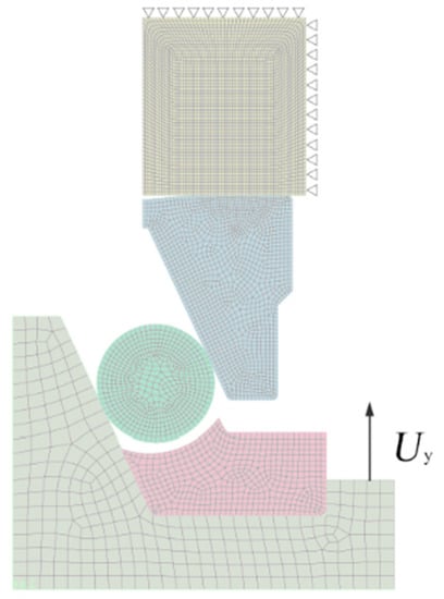
Figure 3.
Finite element model of SEMS2. (Uy is the interference along the axis).
Furthermore, the unit force load and heat flow rate are applied to each node of the rotor and stator, respectively [28]. The influence coefficient matrixes of mechanical deformation and thermal deformation are established, and the total deformation of the sealing faces at each node is obtained.
2.2.4. Dynamic Analysis
Under transient conditions at the bottom of the well, the continuously changing load acts on the metal sealing rings and the stator forms a dynamic floating seal with the rotor. The SEMS2 is simplified and analyzed by force analysis, as shown in Figure 4. The thermal viscoelasticity of the auxiliary rubber seals has a damping effect on the movement of the stator. The dynamic equation of the floating stator under axial disturbance is established by ignoring the installation misalignment and deflection, provided as
where m is the mass of the stator and auxiliary seals, c is the axial damping coefficient of the auxiliary seals, k is the axial stiffness coefficient of the auxiliary seals, and Fd is the axial load caused by disturbance.
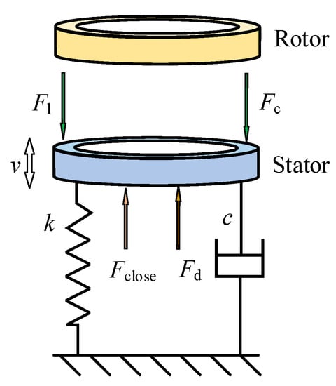
Figure 4.
Dynamic analysis of SEMS2.
The axial load (Fd) varies with the following disturbance forms of drill bits:
- Periodic axial vibration
Assume that the excitation load borne by the sealing system is simple harmonic excitation. When the axial vibration is sinusoidal [29,30], Fd can be expressed as
where A is the amplitude of the axial load.
- 2.
- Instantaneous shock during periodic vibration
While periodically vibrating, the drill bits are inevitably subject to instantaneous shock at a certain moment. It is necessary to consider the effect of the instantaneous impact load (Fs) on the dynamic performance of the metal seals. Fd can be expressed as
- 3.
- Random vibration
In the actual drilling process, the forces on the roller cone bits are very complicated and random. Based on the vibration analysis of the cone bits [31,32], the trigonometric compound function of the rotational speed and axial load is deduced to simulate the random vibration of SEMS2.
The axial load and angular velocity of the drill bits can be written as
where is the average load, is the dynamic load, is the average angular velocity, and is the dynamic angular velocity.
The dynamic angular velocity () is assumed as
where Aω is the amplitude of the angular velocity, which changes with the relative speed of the cone, and β is the phase between the driving device and the cone bits.
The angular velocity is expressed as
Therefore, the axial load (Fd) can be expressed as
2.3. Calculation Process and Verification
2.3.1. Calculation Process
The finite difference method and the Newmark method were used in the calculation. First, the space domain and the time domain of SEMS2 were discretized. The coupling solution of Reynolds equations, dynamics equations, etc., were obtained by the multiple numerical iteration method. The thermal–fluid–solid–dynamic coupling calculation process is shown in Figure 5. In the innermost cycle, the parameters in Reynolds equation are iterated using the five-point difference method to determine the convergence of liquid film pressure. In the second cycle, the equilibrium film thickness affected by thermal deformations of rotor and stator is calculated using the influence factor method, and the film thickness relaxation iteration is carried out. In the third layer, the film thickness satisfying the dynamic equation is adjusted by the dichotomous method and the axial velocity is updated. The outermost layer is the time-item program loop which iterates to the end of a specific moment.
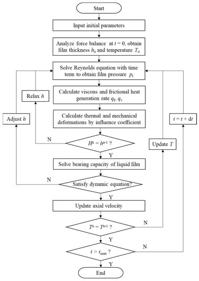
Figure 5.
Flow chart of coupling calculation.
First, the film thickness and the interface temperature of SEMS2 at the initial time are obtained through the steady-state thermal–fluid–solid coupling. Then, a quasi-steady-state thermal–fluid–solid coupling analysis is performed at each time. By solving the Reynolds equation with a time term, the distribution of the liquid film pressure (pl) is obtained, and the heat flux (q) can be calculated. The deformations of the end faces of the rotor and stator are obtained by the influence coefficient method, and the film thickness (h) is relaxed and iteratively updated. Furthermore, the dynamic equation is solved by the Newmark method, and the interface temperature (T) is updated. Finally, the program is ended by judging whether the specified time has been reached.
2.3.2. Model Verification
The steady-state results of metal seals obtained by simulation have been verified with the experimental results in the literature [20]. On this basis, the calculation results of the multi-field coupling model and method proposed in this study were compared with results from the literature [33] to verify their accuracy. The parameters of the mechanical seals in the above literature were substituted into the numerical model of this study to solve the dynamic performance. The calculated values and reference values of the liquid film pressure (pl) and liquid film thickness (h) on the sealing end faces are compared at different times (t = 1 s, 5 s, and 10 s) in Figure 6. It can be seen that the radical changes in the liquid film pressure (pl) and film thickness (h) obtained by the model in this study are consistent with those obtained in the literature at three times, and their corresponding values are in good agreement with each other. The relative errors of the liquid film pressure (pl) and liquid film thickness (h) both reach their maximum values (7.78% for pl at t = 1 s and 7.79% for h at t = 10 s) near the inner diameter side (= r/ro = 0.93) of the sealing end faces. This may be because we considered the influence of the viscosity–temperature effect on the fluid medium in this study. Therefore, the comprehensive numerical model established in this study is suitable for predicting the multi-field coupling effect and dynamic characteristics of metal seals.
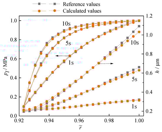
Figure 6.
Model verification [33].
3. Results and Discussion
3.1. Influence of Periodic Vibrations
The three-dimensional distributions of the film thickness ratio (h/σ), dimensionless contact pressure (c = pc/poi), and interface temperature increase (Δ= ΔT/Toi) on the end faces of SEMS2 under periodic vibration are shown in Figure 7. The radial changes in liquid film thickness (h/σ), dimensionless contact pressure (c), and temperature increase (Δ) on the sealing end faces at the characteristic times (t1~t4) in Figure 7a are analyzed in Figure 8.
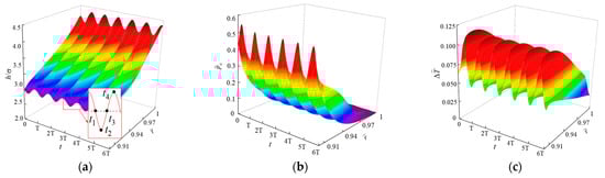
Figure 7.
Three-dimensional distributions of film thickness ratio, contact pressure, and temperature increase under periodic vibration. (a) Film thickness ratio, (b) Contact pressure (c), Temperature increase.
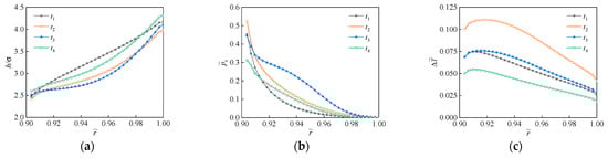
Figure 8.
Radial distributions of film thickness ratio, contact pressure, and temperature increase. (a) Film thickness ratio, (b) Contact pressure, (c) Temperature increase.
The film thickness ratio (h/σ), dimensionless contact pressure (c) and temperature increase (Δ) of the SEMS2 fluctuate sinusoidally, with significantly different oscillation amplitudes at each radial position. This is related to the dynamic balance of the opening and closing forces between the sealing faces of the rotor and stator under alternating excitation loads. When the stator is excited to squeeze toward the rotor, the gap between the end faces and the liquid film thickness decrease, while the contact pressure and opening force increase. The forces between the end faces of the rotor and stator tend to be balanced, and the sealing system reaches a stable state again. When the stator is excited away from the rotor, the above changes are the opposite. Therefore, the characteristic parameters of the liquid film on the sealing end faces fluctuate in a stable range under periodic vibration.
The film thickness ratio (h/σ) on the end faces appears to be an oscillating radial divergence distribution with a relatively stable frequency under poi = 30 MPa, ni = 200 r/min. The mechanical and thermal deformations of the rotor and stator make the thickness of the liquid film in the gap between the sealing end faces gradually increase in the radial direction. According to the values of the film thickness ratio (h/σ), the lubrication state of the sealing end face changes from mixed lubrication on the inner diameter side (ID) to full liquid film lubrication on the outer diameter side (OD). The changes in film thickness at each characteristic time (t1~t4) differ in their response times due to the phase difference. The amplitude of the maximum film thickness (hmax) on the OD can reach twice the amplitude of the minimum film thickness (hmin) on the ID under periodic vibration. It is very easy to aggravate the leakage of lubricating oil from the OD of the sealing rings.
The mean value and vibration amplitude of the contact pressure (c) on the end faces of the SEMS2 decrease with the radius (). The contact pressure (c) reaches a maximum value (0.55) on the ID at t2 and disappears on the OD at t1~t4. Because of the uncontacted asperities, the sealing rings are entirely carried by the liquid film pressure on the OD. Therefore, the lubricating oil in the inner cavity of SEMS2 has difficulty entering the sealing gap under environmental pressure poi = 30 MPa.
The interface temperature increase (Δ) on the end faces at each time increases first and then decreases with the radius (). The vibration amplitude of the maximum temperature increase (Δmax) near the ID (about = 0.91) reaches 2.8 times that of the minimum temperature increase (Δmin) on the OD under periodic vibration. Particularly at time t2, the maximum difference of the interface temperature increase (Δ) along the radial direction exceeds 63%. The temperature increase distribution of the sealing rings at different times is further analyzed in Figure 9. Affected by the heat transfer on the end faces, the temperature increase (Δ) of the rotor and stator gradually decreases from the ID of the end faces outward. The end faces near the ID side bear most of the contact pressure, and frictional heat is gradually generated due to the contact of the micro-asperities between the end faces. On the other hand, the heat exchange capacity of the OD side of the rotor and stator gradually enhances. The changing gradient of the temperature is particularly obvious for the rotor, causing the overall temperature increase of the rotor to be lower than that of the stator. This makes the thermal deformation of the end face of the stator larger than that of the end face of the rotor.
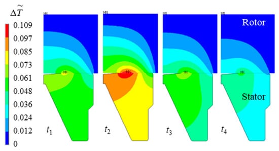
Figure 9.
Temperature increase distribution contours of sealing rings at four times (t1, t2, t3, t4).
The influences of different operating conditions on the sealing performance of SEMS2 are investigated. Time-domain and frequency-domain changes in dimensionless maximum temperature increase (Δmax), leakage rate (), and friction torque () with dimensionless environmental pressures (o = po/poi) and rotational speeds ( = n/ni) under periodic vibration are shown in Figure 10 and Figure 11, respectively. The frequency domain results were obtained using a Fast Fourier Transform (FFT) on the time domain results.
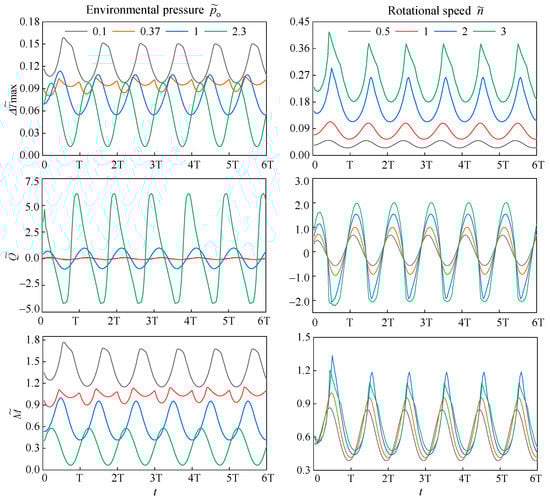
Figure 10.
Changes in maximum temperature increase, leakage rate, and friction torque on end faces under periodic vibration.
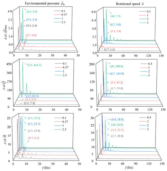
Figure 11.
Spectrum diagram of maximum temperature increase, leakage rate, and friction torque on end faces under periodic vibration.
The dynamic maximum temperature increase, leakage rate, and friction torque maintain stable vibration frequency and amplitude except for the initial moment. When the environmental pressure (o) increases from 0.1 to 2.3, the mean values of the maximum temperature increase (Δmax) and friction torque () on the sealing faces decrease by 56% and 77%, respectively. This is related to the decreasing frictional heat and contact force of the micro-asperities and the enhanced heat transfer capacity of the sealing boundary. The variation amplitude of the maximum temperature increase (Δ) and friction torque () decreases first and then increases, and reaches the minimum value when o = 0.37. Through the radial changes of liquid film thickness with the environmental pressure (o), the environmental pressure o = 0.37 is the turning point from a convergent liquid film to a divergent liquid film. The amplitudes of the maximum temperature increase (Δ) under o = 2.3 reach 1.4 times the value of those under o = 0.1.
The leakage rate () fluctuates alternately between positive and negative under periodic vibration. When the leakage rate is positive, the lubricating oil on the ID side of SEMS2 flows to the OD side. When the leakage rate is negative, the drilling mud on the OD side of SEMS2 may flow into the sealing gap. As the environmental pressure (o) increases, the position of the minimum film thickness gradually changes from the OD to the ID. This means that the lubrication state of the ID side of the end faces deteriorates, and the leakage tendency of the lubricating oil increases under high environmental pressure. Due to the squeezing effect and viscosity change of the liquid film, the mean value and amplitude of the leakage rate () increase with the environmental pressure (o). Especially when the environmental pressure o = 2.3, the peak value of the leakage rate () reaches 6.1, far exceeding the maximum allowable leakage rate of the metal seals.
As the rotational speed () increases from 0.5 to 3, the vibration amplitudes of the maximum temperature increase (Δ, leakage rate (), and friction torque () gradually increase. The mean values of maximum temperature increase (Δ), leakage rate (), and friction torque () when = 3 reach more than 5.9, 5.8, and 1.2 times their values when = 0.5, respectively. This is attributed to the continuous generation of contact friction heat and viscous shear heat with increasing rotational speed. The sealing gap diverges more severely by thermal deformations, and the viscosity of the lubricating oil between the end faces decreases. Therefore, the lubricating oil inside the SEMS2 is more likely to leak out in the downhole environment with high temperature, high pressure, and high rotational speed. In addition to the influence of vibration, drilling mud may invade the sealing gap and aggravate the wear on the end faces. This indirectly damages the bearing system and affects the long-term operation of the roller cone bits.
The amplitude spectra under the initial conditions reveal that the pulsations of the maximum temperature increase (Δ), leakage rate (), and friction torque () decrease periodically, mainly in the low-frequency range of 0~50 Hz. These vibration amplitudes are generated at an integer multiple of the rotation frequency (fn = n/60) of the drill bits. The corresponding frequency is fi = kfn, where k is a positive integer. Except for the environmental pressure o = 0.37, the dominant frequency of these three performance parameters is the rotation frequency, and the corresponding amplitudes increase with the environmental pressure. As the rotational speed () increases from 0.5 to 3, the range of these fluctuation frequencies increases proportionally, and the dominant frequency amplitudes of the maximum temperature increase (Δ), leakage rate (), and friction torque () increase by 6 times, 2.4 times, and 20%, respectively.
3.2. Influence of Instantaneous Shock
Due to the complexity of bottom hole drilling, the operation of the cone bits may be affected by instantaneous impacts. Here, we assume that the SEMS2 is subjected to a sudden load (Fs = 5 kN) at ts = 1.5T while periodically vibrating. Time-domain and frequency-domain changes in dimensionless maximum temperature increase (Δ), leakage rate (), and friction torque () with dimensionless environmental pressures (o) and rotational speeds () under periodic vibration and instantaneous shock are shown in Figure 12 and Figure 13, respectively.
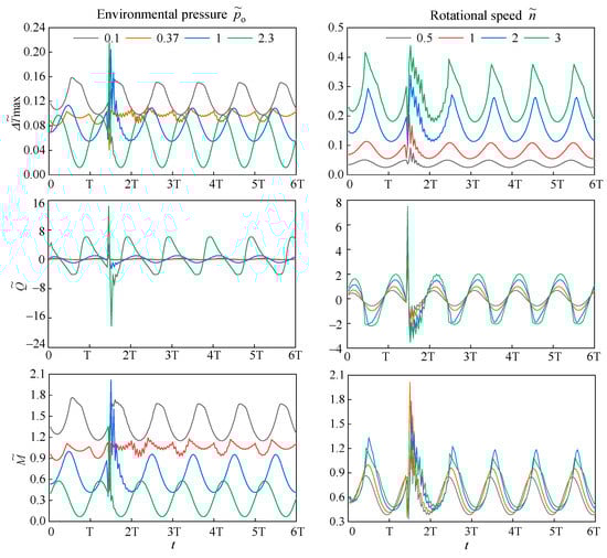
Figure 12.
Changes in maximum temperature increase, leakage rate, and friction torque on end faces under periodic vibration and instantaneous shock.
Figure 13.
Spectrum diagram of maximum temperature increase, leakage rate, and friction torque on end faces under periodic vibration and instantaneous shock.
When the SEMS2 initially in stable vibration is subjected to an instantaneous impact (t = ts), the maximum temperature increase (Δ), leakage rate (), and friction torque () change greatly with the abrupt change of the sealing gap. Affected by different phases, the valleys of maximum temperature increase (Δ) and friction torque () decrease obviously when o < 1. However, due to the instantly thinned liquid film, the maximum temperature increase (Δ) and friction torque () surge significantly when o ≥ 1. Compared with the two above parameters, the leakage rate () is more sensitive to instantaneous impact. Due to the extrusion between the sealing end faces, the pressure difference of the liquid film on the end faces increases immediately. The peak and valley values of the leak rate () with o = 2.3 reach 52.4 and 165 times, respectively, of those with o = 0.1. Especially, the negative leakage rate caused by mud intrusion flow increases significantly under high environmental pressure. Different from the environmental pressure, the duration of the shock vibration cycle at different rotational speeds can be up to twice that of the former. Therefore, instantaneous impact on the SEMS2 may lead to serious leakage of lubricating oil and intrusion of drilling mud into the sealing cavity.
After the instantaneous impact disappears, the main waveforms of the maximum temperature increase (Δ), leakage rate (), and friction torque () continue to oscillate at a high frequency for a period of time. Affected by the liquid film pressure on the end faces and the damping action of the O-ring and backup ring, the amplitude and frequency of the micro-fluctuations attenuate gradually with time. The duration of the shaking oscillation increases first and then decreases with the environmental pressure (o), and reaches its maximum value at o = 0.37. An instantaneous impact at high rotational speed has a more obvious effect on the values and oscillation time of the maximum temperature increase (Δ), leakage rate (), and friction torque (). In addition, the gradient of the temperature increase curve at the peak varies greatly at high rotational speeds, which makes the temperature increase (Δ) prone to sharply changing in a short time, thus affecting the leakage rate () and friction torque (). With the increase in the rotational speed () from 0.5 to 3, the peak values of the maximum temperature increase (Δ) and leakage rate () after the instantaneous shock increase by 3.75 and 1.78 times, respectively.
It can be seen from the spectrum results that the pulsation amplitudes of the three performance parameters of SEMS2 increase slightly under periodic vibration and instantaneous shock. The maximum amplitude of maximum temperature increase (Δ) and leakage rate () increase geometrically during the transition of working conditions from low environmental pressure and rotational speed to high environmental pressure and rotational speed. Similar to the results of periodic vibration, the amplitudes of maximum temperature increase (Δ), leakage rate (), and friction torque () are obviously attenuated from the dominant frequency to the sub-frequencies. However, the waveforms of these performance parameters after instantaneous shock generate more multiple frequencies, and the intensity of the mid-frequency and high-frequency fluctuations increase as a whole. The changes in the spectrum amplitude of the sealing performance parameters with environmental pressure or rotational speed under periodic vibration and instantaneous shock are consistent with those under periodic vibration.
3.3. Influence of Random Vibration
According to the actual vibration form of the drill bits, the influence of random vibration on the SEMS2 is considered by applying dynamic components to the rotational angular velocity and axial load. Time-domain and frequency-domain changes in the dimensionless maximum temperature increase (Δ), leakage rate (), and friction torque () with dimensionless environmental pressures (o) and rotational speeds () under random vibration are shown in Figure 14 and Figure 15, respectively.
Figure 14.
Changes in maximum temperature increase, leakage rate, and friction torque on end faces under random vibration.
Figure 15.
Spectrum diagram of maximum temperature increase, leakage rate, and friction torque on end faces under random vibration.
The sealing performance parameters of SEMS2 change in the composite state of random and periodic vibrations. With the rotation of the drill bit, the vibration frequencies of the maximum temperature increase (Δ), leakage rate (), and friction torque () gradually increase, corresponding to more oscillating waveforms. The amplitudes of these three parameters under random vibration are significantly larger than those of the periodic vibration. In particular, the leakage rate () of the SEMS2 vibrates randomly, with more intense alternating positive and negative values. The sealing end faces bear the repeated intrusion of the leaking lubricating oil and the invading drilling mud, and the fluid lubrication state on the end faces evolves instantaneously. Mud particles may gradually accumulate in the sealing gap, significantly increasing abrasive wear on the sealing faces. Therefore, the sealing performance of the SEMS2 faces severe challenges under variable speed and variable load, and the deformation and wear of the sealing faces become more serious.
Affected by random vibration, the spectral waveforms of the maximum temperature increase (Δ), leakage rate (), and friction torque () oscillate more irregularly. Compared with the results with periodic vibration and instantaneous shock, more intense spectrum oscillation and more disordered amplitude distribution appear in the corresponding frequency range under random vibration. The spectrum waveform of the maximum temperature increase (Δ) on the end faces maintains the dominant frequency as the rotation frequency. The frequency doubling component is determined by the random vibration of the trigonometric function in Formula (14). The dominant-frequency amplitude of the maximum temperature increase (Δ) decreases by 74.5% with the increase in the environmental pressure (o) and increases by 6.5 times with the increase in the rotational speed (). When o ≤ 0.37, the dominant frequency amplitude of the friction torque () is significantly larger than that of other frequencies. However, the waveform of the friction torque () jitters significantly under high environmental pressure. The spectrum waveform of the leak rate () is more chaotic, with no apparent dominant frequency compared to that of the maximum temperature increase (Δ) and friction torque (). The disorder of the spectrum is more significant, and the maximum amplitude of the leak rate () under random vibration increases by 80 and 1.7 times with the increase in environmental pressure (o) and rotational speed (), respectively.
The maximum peak values of the time-domain and frequency-domain results of the maximum interface temperature increase (PT-t, PT-f), leakage rate (PQ-t, PQ-f), and friction torque (PM-t, PM-f) under three kinds of vibration are compared in Figure 16. The fluctuation amplitudes of the maximum temperature increase (Δ), leakage rate (), and friction torque () under random vibration and instantaneous shock are significantly larger than those under periodic vibration. The stability of the sealing system gradually deteriorates under complex working conditions. This phenomenon is very similar to the wear and mud packing in actual operation of the first-generation single energizer metal seals (SEMS) in the literature [6] as well as the wear test results of double energizer metal seals (DEMS) in roller cone bits in the literature [34].
Figure 16.
Comparisons of time-domain and frequency-domain peaks under different vibrations.
When o ≤ 1, random vibration has a more significant effect on the maximum interface temperature increase (Δ) and friction torque () than instantaneous shock, which is the opposite when the environmental pressure is higher. The time-domain peaks of the maximum temperature increase and friction torque (PT-t, PM-t) under instantaneous shock can reach more than two times those under periodic vibration when o = 2.3. As the environmental pressure (o) increases, the gradient of leakage rate () changes more obviously with the three vibrations. When o = 2.3, the time-domain peak of the leakage rate (PQ-t) under instantaneous shock and random vibration can reach more than three times that under periodic vibration. Under the three vibrations, the time-domain peaks of the maximum temperature increase and leakage rate (PT-t, PQ-t) both increase with the rotational speed. However, the time-domain peak of the friction torque (PM-t) increases first and then decreases with the rotational speed (). The more significant effects of random vibration and instantaneous shock on the time-domain peaks of these three sealing parameters can be found at lower rotational speeds ( < 1) than at higher rotational speeds.
Under the three vibration forms, the frequency-domain peak of the leakage rate (PQ-f) increases obviously with the environmental pressure (o) and rotational speed (). The superposition of the instantaneous shock causes a slight change in the peaks of the maximum temperature increase, leakage rate, and friction torque (PT-f, PQ-f, PM-f) under periodic vibration. However, affected by the random vibration, the spectral waveform of the sealing performance parameters fluctuates more severely in the frequency range. The result is that the values and changing rules of the frequency-domain peaks under random vibration are quite different. The frequency-domain peaks of the maximum temperature increase (PT-f) under random vibration are larger than those under the other two vibrations, except for o = 2.3. However, the frequency-domain peaks of the friction torque (PM-f) are smaller than those under the other two vibrations, except for o ≤ 0.37. With increasing environmental pressure (o) and rotational speed (), the frequency-domain peaks of the leakage rate (PQ-f) under random vibration remain weaker than those under the other two vibrations.
Therefore, the SEMS2 can withstand vibration excitation to a certain extent due to the bearing of the liquid film on the end faces of the metal sealing rings and the damping effect of the auxiliary rubber rings. However, the comprehensive performance of the SEMS2 easily deteriorates under complex vibrations or sudden shock. Especially in the drilling environment with high pressure and high rotational speed, the anti-vibration and wear-resistant performance of the SEMS2 urgently needs to be strengthened.
4. Conclusions
In this work, a dynamic mathematical model of new-generation single energizer metal seals (SEMS2) in roller cone bits is established based on the multi-filed coupling relationship to predict the sealing performance of the SEMS2 when subjected to vibrations. The numerical method and results have been validated with results from the literature. The influence of periodic vibration, instantaneous shock, and random vibration on the lubrication state and sealing parameters of SEMS2 are analyzed under various environmental pressures and rotational speeds. The establishment of this model is very important for improving the design system of metal seals in roller cone bits. The conclusions are summarized as follows:
- Affected by the high environmental pressure (poi = 30 MPa) and periodic excitation, the film thickness on the sealing end faces appears to have a divergent oscillating distribution along the radial direction. The vibration ranges of the maximum thickness ratio (h/σ) and interface temperature increase (Δ) reach more than two times those of the minimum values. The spectral amplitudes of the performance parameters of the SEMS2 are generated at an integer multiple of the rotation frequency (fn) of the drill bit. It is worth noting that the instantaneous leak rate () fluctuates alternately between positive and negative. When the leakage rate is negative, the mud on the OD side can easily intrude into the sealing gap, aggravating the wear on the end faces.
- When subjected to an instantaneous shock, the liquid film on the end faces of the SEMS2 is squeezed, and the maximum temperature increase (Δmax) and friction torque () change abruptly. Due to the pressure difference of the liquid film on the end faces, the negative leakage rate caused by mud intrusion increases more significantly than the positive leakage rate caused by lubricating oil escape, especially at o = 2.3. Afterwards, the sealing performance parameters oscillate and decay until stable periodic fluctuation is restored. Under quasi-real random vibration, more intense spectral oscillation and disordered amplitude distribution appear in the frequency range.
- With increasing environmental pressure (o) and rotational speed (), the fluctuation amplitudes of the maximum temperature increase (Δ) leakage rate (), and friction torque () under random vibration and instantaneous shock are significantly larger than those under periodic vibration. When o ≤ 1, random vibration has a more significant effect on the maximum interface temperature increase (Δ) friction torque () than instantaneous shock, which is the opposite when the environmental pressure is higher.
In a further study, the stability and reliability of the SEMS2 in the roller cone bits could be improved by comprehensive optimization of the composition form, primary structure and size, and material parameters of the metal rings and auxiliary rings.
Author Contributions
Conceptualization, Y.M., Y.C. and X.P.; methodology, Y.C.; software, Y.X.; validation, Y.X. and Y.C.; formal analysis, Y.M. and X.M.; investigation, Y.M. and X.M.; data curation, Y.M. and Y.X.; writing—original draft preparation, Y.M. and Y.C.; writing—review and editing, X.P.; supervision, X.P. All authors have read and agreed to the published version of the manuscript.
Funding
This research was funded by the National Natural Science Foundation of China (Grant No. 51975527, U1737202).
Data Availability Statement
Not applicable.
Acknowledgments
The authors would like to thank the National Natural Science Foundation of China (Grant No. 51975527, U1737202) for the financial support.
Conflicts of Interest
The authors declare no conflict of interest.
References
- Wang, J.L.; Qian, D.L.; Sun, Y.; Peng, F.F. Design of diamond bits water passage system and simulation of bottom hole fluid are applied to seafloor drill. J. Mar. Sci. Eng. 2021, 9, 1100. [Google Scholar] [CrossRef]
- Rossi, E.; Saar, M.O.; von Rohr, P.R. The influence of thermal treatment on rock-bit interaction: A study of a combined thermo-mechanical drilling (CTMD) concept. Geotherm. Energy 2020, 8, 16. [Google Scholar] [CrossRef]
- Chen, L.; Hu, C.; Yang, Y.X.; Bao, Z.J.; Niu, S.W.; Chen, X.W.; Chen, X.; Zhang, W.T. Experimental research on working principle of the composite single-cone bit. J. Petrol. Sci. Eng. 2021, 205, 108932. [Google Scholar] [CrossRef]
- Abbas, R.K.; Ghanbarzadeh, A.; Hassanpour, A. A novel method for estimating the real-time dullness of tri-cone oil drill bits. Eng. Fail. Anal. 2020, 109, 104386. [Google Scholar] [CrossRef]
- Abbas, R.K. A review on the wear of oil drill bits (conventional and the state of the art approaches for wear reduction and quantification). Eng. Fail. Anal. 2018, 90, 554–584. [Google Scholar] [CrossRef]
- Grimes, B.; Kirkpatrick, B. Step change in performance: Upgraded bit technology significantly improves drilling economics in GOM motor applications. In Proceedings of the SPE Annual Technical Conference and Exhibition, San Antonio, TX, USA, 24–27 September 2006. [Google Scholar]
- Suto, Y.; Takahashi, H. Effect of the load condition on frictional heat generation and temperature increase within a tri-cone bit during high-temperature formation drilling. Geothermics 2011, 40, 267–274. [Google Scholar] [CrossRef]
- de Moura, J.; Xiao, Y.J.; Yang, J.M.; Butt, S.D. An empirical model for the drilling performance prediction for roller-cone drill bits. J. Petrol. Sci. Eng. 2021, 204, 108791. [Google Scholar] [CrossRef]
- Naganawa, S. Feasibility study on roller-cone bit wear detection from axial bit vibration. J. Petrol. Sci. Eng. 2012, 82–83, 140–150. [Google Scholar] [CrossRef]
- Deng, Y.; Chen, M.A.; Jin, Y.; Zhang, Y.K.; Zou, D.W.; Lu, Y.H. Theoretical and experimental study on the penetration rate for roller cone bits based on the rock dynamic strength and drilling parameters. J. Nat. Gas Sci. Eng. 2016, 36 Pt A, 117–123. [Google Scholar] [CrossRef]
- de Moraes, L.P.P.; Savi, M.A. Drill-string vibration analysis considering an axial-torsional-lateral nonsmooth model. J. Sound Vib. 2019, 438, 220–237. [Google Scholar] [CrossRef]
- Moharrami, M.J.; Martins, C.D.; Shiri, H. Nonlinear integrated dynamic analysis of drill strings under stick-slip vibration. Appl. Ocean Res. 2021, 108, 102521. [Google Scholar] [CrossRef]
- Zhao, Y.; Zhang, C.S.; Zhang, Z.Z.; Gao, K.; Li, J.S.; Xie, X.B. The rock breaking mechanism analysis of axial ultra-high frequency vibration assisted drilling by single PDC cutter. J. Petrol. Sci. Eng. 2021, 205, 108859. [Google Scholar] [CrossRef]
- Zhang, B.S.; Chen, J.Q.; Si, R. The new-type single metal floating seal for roller bits. China Petrol. Mach. 2009, 37, 32–35. [Google Scholar]
- Zhou, Y.; Huang, Z.Q.; TAN, L.; Ma, Y.C.; Qiu, C.S.; Zhang, F.X.; Yuan, Y.; Sun, C.M.; Guo, L. Cone bit bearing seal failure analysis based on the finite element analysis. Eng. Fail. Anal. 2014, 45, 292–299. [Google Scholar] [CrossRef]
- Zhang, Y.; Zhang, X.D.; Chang, X.P.; Wu, Q. Wear morphology analysis and structural optimization of cone bit bearing seals. Ind. Lubr. Tribol. 2018, 70, 59–67. [Google Scholar] [CrossRef]
- Zhang, Y.; Zhang, X.D.; Yang, L.; Yu, X. Optimization design for downhole dynamic seal based on response surface method. Adv. Mech. Eng. 2019, 11, 1687814019828441. [Google Scholar] [CrossRef]
- Xiong, S.; Salant, R.F. A numerical model of a rock bit bearing seal. Tribol. Trans. 2000, 43, 542–548. [Google Scholar] [CrossRef]
- Xiong, S.; Salant, R.F. A non-axisymmetric steady state model of a mechanical seal for downhole tools. J. Tribol. 2002, 124, 144–150. [Google Scholar] [CrossRef]
- Ma, Y.; Yuan, Z.Y.; Ni, Y.; Meng, X.K.; Peng, X.D. Performance prediction and multi-objective optimization of metal seals in roller cone bits. J. Petrol. Sci. Eng. 2022, 208 Pt A, 109316. [Google Scholar] [CrossRef]
- Xiong, S.; Salant, R.F. A dynamic model of a contacting mechanical seal for down-hole tools. J. Tribol. 2003, 125, 391–402. [Google Scholar] [CrossRef]
- Zhang, X.D.; Zhang, Y.; Li, Y.L.; Zhang, Y.; Luo, Y. Container design and contact research of single metal seal. Mach. Design Res. 2013, 29, 132–137. [Google Scholar]
- Zhang, M.T.; Feng, Y. Numerical model of mixed lubrication and experimental study of reciprocating seal based on inverse lubrication theory. Lubricants 2022, 10, 153. [Google Scholar] [CrossRef]
- Jiang, J.B.; Zhao, W.J.; Peng, X.D.; Li, J.Y. A novel design for discrete surface texture on gas face seals based on a superposed groove model. Tribol. Int. 2020, 147, 106269. [Google Scholar] [CrossRef]
- Patir, N.; Cheng, H.S. Application of average flow model to lubrication between rough sliding surfaces. J. Lubr. Technol. 1979, 101, 220–227. [Google Scholar] [CrossRef]
- Cui, S.H.; Gu, L.; Fillon, M.; Wang, L.Q.; Zhang, C.W. The effects of surface roughness on the transient characteristics of hydrodynamic cylindrical bearings during startup. Tribol. Int. 2018, 128, 421–428. [Google Scholar] [CrossRef]
- Gao, B.C.; Meng, X.K.; Li, J.Y.; Shen, M.X.; Peng, X.D. Thermal-mechanical coupled finite element model and seal performance analysis of mechanical seals. Tribology 2015, 35, 550–556. [Google Scholar]
- Abouelregal, A.E.; Marin, M. The response of nanobeams with temperature-dependent properties using state-space method via modified couple stress theory. Symmetry 2020, 12, 1276. [Google Scholar] [CrossRef]
- Henneuse, H. Surface detection of vibration and drilling optimization field experience. In Proceedings of the SPE/IADC Drilling Conference, New Orleans, LA, USA, 18–21 February 1992. [Google Scholar]
- Chen, Y.; Peng, X.D.; Jiang, J.B.; Meng, X.K.; Li, J.Y. Experimental and theoretical studies of the dynamic behavior of a spiral-groove dry gas seal at high-speeds. Tribol. Int. 2018, 125, 17–26. [Google Scholar] [CrossRef]
- Aarrestad, T.V.; Kyllingstad, A. An experimental and theoretical study of a coupling mechanism between longitudinal and torsional drillstring vibrations at the bit. SPE Drill. Eng. 1988, 3, 12–18. [Google Scholar] [CrossRef]
- Liu, J.X.; Zheng, H.L.; Kuang, Y.C.; Yu, B.; Zhou, Y.; Deng, M. A feasible model for friction-reduction investigation of drillstrings in long-horizontal wells with axial oscillation tools and analysis of key influencing factors. J. Petrol. Sci. Eng. 2020, 185, 106643. [Google Scholar] [CrossRef]
- Zhang, X.M. Research on Dynamic Characteristics of Marine Mechanical Seals; Wuhan University of Technology: Wuhan, China, 2008. [Google Scholar]
- Huang, Z.Q.; Li, G. Optimization of cone bit bearing seal based on failure analysis. Adv. Mech. Eng. 2018, 10, 1687814018767485. [Google Scholar] [CrossRef]


Publisher’s Note: MDPI stays neutral with regard to jurisdictional claims in published maps and institutional affiliations. |
© 2022 by the authors. Licensee MDPI, Basel, Switzerland. This article is an open access article distributed under the terms and conditions of the Creative Commons Attribution (CC BY) license (https://creativecommons.org/licenses/by/4.0/).