Article

Influence of Structural and Operating Parameters on Lubrication Performance of Water-Lubricated Polymer Bearing with Journal Misalignment

1
College of Mechanical and Electrical Engineering, Hohai University, Changzhou 213022, China
2
Institute of Vibration, Shock and Noise, State Key Laboratory of Mechanical System and Vibration, Shanghai Jiao Tong University, Shanghai 200240, China
3
Tianjin Navigation Instruments Research Institute, Tianjin 300131, China
4
Department of Mechanical Engineering, Xi’an Jiaotong University City College, Xi’an 710018, China
*
Author to whom correspondence should be addressed.
Lubricants 2022, 10(12), 336; https://doi.org/10.3390/lubricants10120336
Submission received: 3 November 2022 / Revised: 21 November 2022 / Accepted: 23 November 2022 / Published: 28 November 2022
(This article belongs to the Special Issue Tribological Characteristics of Bearing System)

Abstract

:
Marine water-lubricated polymer bearings support the propeller shaft that stretches out of the ship. The bending deformation of propeller shaft often leads to journal misalignment, significantly impacting the bearing performance. In this paper, a mixed lubrication model for water-lubricated polymer bearing is established considering the effect of journal misalignment, liner elastic deformation, and local turbulence. The influence of key structural and operating parameters on the performance of water-lubricated bearing with journal misalignment is investigated. The results show that the journal misalignment significantly reduces the load-carrying capacity, deteriorates the bearing tribological characteristics, and may cause different axial sections of the bearing to be in different lubrication regimes. Compared with aligned bearings, increasing the length–diameter ratio to improve the load-carrying capacity is significantly weakened for misaligned bearings. Increasing the liner thickness and the load improves axial uniformity of pressure distribution of misaligned bearings. A relatively large clearance ratio decreases the load-carrying capacity and increases the friction coefficient of bearings in the mixed lubrication regime.

1. Introduction

In the research on journal bearings, the journal centerline is usually assumed to be parallel to the bearing hole’s centerline. However, in engineering practice, due to manufacturing, assembly and installation errors, shafting vibration, load distribution, and other factors, the shaft sometimes bends in operation. Thus, an included angle is generated between the journal centerline and the bearing hole centerline. Marine water-lubricated polymer bearing supports the propeller shaft. The large bending deformation of propeller shaft often misaligns the bearing in the vertical direction. Journal misalignment has an important impact on the bearing performance and dynamic performance of the shaft-bearing system. Moreover, due to low lubricant viscosity, the elastic modulus of polymer liner, and journal speed, water-lubricated polymer bearings often operate in mixed lubrication regimes and are prone to large elastic deformation and turbulent flow. The particularities of water-lubricated bearings have attracted the research interest of many scholars [1,2,3,4].
Some researchers investigated journal misalignment or shaft bending. Zhang et al. [5] established a thermal elastohydrodynamic lubrication model for the misaligned bearing. Their research showed that thermal effect and bearing deformation significantly influence the performance of a misaligned bearing. Litwin et al. [6] investigated the load-carrying capacity of misaligned journal bearing with elastic liner. They pointed out that the load-carrying capacity almost linearly decreases with the increase of misalignment angle for the same minimum water film thickness. Mallya et al. [7] analyzed the influence of journal misalignment on the performance of grooved bearings and indicated that the friction coefficient decreases with an increase in the misalignment angle in the vertical direction. He et al. [8,9] analyzed the influence of journal bending on marine stern tube bearing and pointed out that bending of the journal increases the transition speed from mixed lubrication to pure hydrodynamic lubrication. Zhang et al. [10] investigated the relationship between the ultimate load-carrying capacity and misalignment angle of a misaligned water-lubricated rigid bearing by assuming the included angle between the journal inclination direction and the connecting line from the journal center to the center of the bearing hole is known. Zhu et al. [11] analyzed the influence of journal misalignment on the performance of a rough bearing. The results showed that journal misalignment significantly impacts bearing performance. Jang and Khonsari [12] proposed an evaluation model for the impact of wear on engine bearings with journal misalignment. They pointed out that journal misalignment increases the maximum wear depth, which increases with surface roughness. Xiang et al. [13] analyzed the transient lubrication performance of misaligned journal bearings with three groove structures: straight groove, spiral groove, and herringbone groove. They implied that the load-carrying capacity of the bearing is more sensitive to journal misalignment when considering axial displacement. Song et al. [14] explored the combined influence of cavitation and turbulent flow on the performance of a bearing with journal misalignment. The above research focused on the influence of journal misalignment or shaft bending. However, the structural optimization of misaligned journal bearings is rarely explored.
Some researchers investigated the influence of structure or structural parameters on bearing performance to improve the lubrication performance of water-lubricated bearings. Mallya et al. [15] investigated the influence of axial grooves with circumferential angles of 36° and 18° on the performance of a misaligned bearing. They indicated that increasing the circumferential angle of axial grooves reduces the load-carrying capacity. This observation is consistent with the conclusion of Majumdar et al. [16], who stated that the load-carrying capacity improves when the circumferential angle of the axial groove is smaller. Xiang et al. [17] explored the wear characteristics of grooved bearings and proposed a dynamic wear model for micro-grooved water-lubricated bearings. Hirani and Suh [18] proposed an optimization design method to determine appropriate structural parameters of rigid bearings and minimize power loss and lubricant flow. Chu [19] proposed an algorithm to design sliding of rigid bearings by using a reverse method. Through theoretical and experimental research, Ouyang et al. [20] pointed out that damping structures can significantly improve the dynamic characteristics of water-lubricated bearings. Zhou et al. [21] analyzed the influence of grooves with different shapes on the friction coefficient of water-lubricated bearings. The authors pointed out that the bearing with spiral grooves has better tribological characteristics than the straight grooved bearing. Lv et al. [22] proposed an optimized structure of polymer bearing to improve the lubrication performance of water-lubricated bearings. In recent years, many researchers have noticed that the surface texture can effectively reduce the friction pair’s friction resistance. Therefore, they researched the application of surface texture to bearings [23,24,25,26]. Meng et al. [25,26] explored the influence of compound dimple texture on the tribological properties of bearings. The authors found that compound dimple texture can improve the load-carrying capacity and reduce the bearing friction force and average noise. Gu et al. [27] investigated the time-varying property of an engine bearing accounting for the surface texture and the cavitation effect.
Some research achievements have been made in the structural design of water-lubricated bearings, which is conducive to improving bearing performances. However, most research was based on simplified models and did not comprehensively consider the effects of mixed lubrication, journal misalignment, liner elastic deformation, and lubricant flow pattern transition of water-lubricated bearings. Therefore, the structural design of water-lubricated bearings often cannot be guided well.
In this paper, a mixed lubrication model for water-lubricated polymer bearing is established considering journal misalignment, liner elastic deformation, and local turbulence. The bearing characteristics under different structures and operating parameters are simulated and analyzed. The influence law of key structural and operating parameters on the performance of misaligned water-lubricated bearing is obtained, which provides a reference for the design of water-lubricated bearing with journal misalignment.

2. Modelling

2.1. Geometry of Misaligned Water-Lubricated Polymer Bearing in Mixed Lubrication

Most research on journal bearings assumes that the journal centerline is parallel to the centerline of the bearing hole. However, in engineering practice, the shaft sometimes bends due to factors such as manufacturing, installation, assembly, and gravity, making the journal centerline no longer parallel to the centerline of the bearing hole. Particularly, marine water-lubricated bearing supports the propeller shaft that extends out of the ship. The propeller shaft often bends in the vertical plane. Thus, an angle γ (shown in Figure 1) is generated between the journal centerline and the bearing hole centerline in the vertical plane. Due to the relatively short bearing length compared to the entire shaft, it is assumed that γ is constant in the axial direction. In other words, the bending deformation of the journal in the bearing hole is neglected.
The relative position between the misaligned journal and the bearing is shown in Figure 1. The center of the bearing hole at the journal down-warping end is taken as the origin, and the bearing length direction is the z-axis. The misalignment angle γ is relatively small, so tan γ γ . By introducing the dimensionless quantities λ = 2 z L and ϒ = L 2 c γ (L is the bearing length), the water film thickness at each axial section of the bearing under rigid assumption can be described as follows:
h = c [ 1 + ε z cos ( φ θ z ) ] ,
where c is the radial clearance, ε z is the eccentricity ratio at each axial section, ε z = e z c = λ 2 ϒ 2 - 2 λ ϒ ε cos θ + ε 2 ( ε and θ is the eccentricity ratio and attitude angle of the journal at the axial section where the coordinate origin is located), and θ z is the attitude angle at each axial section, θ z = arctan ( ε sin θ ε cos θ λ ϒ ) .
As shown in Figure 1b, a water-lubricated polymer bearing comprises a metal shell and a polymer liner. Rubber has been one of the most commonly used materials for marine water-lubricated bearings in the past decades. Nonetheless, rubber bearings have certain limitations, such as high friction noise and abnormal vibration. A type of polymer material with main parameters (elastic modulus is 4.4 × 10⁸ Pa and Poisson’s ratio is 0.45) widely accepted in marine applications is often used to replace rubber. This material is a type of thermosetting resin, homogeneous molded material. Compared with rubber, this polymer material has the characteristics of a low friction coefficient under dry friction conditions and a high load-carrying capacity. The elastic modulus of this polymer material is much higher than rubber. Therefore, the elastic deformation of polymer bearings is much lower than rubber bearings. However, the elastic deformation of polymer bearing still significantly impacts the bearing performance. Hence, it is necessary to consider the influence of elastic deformation of a liner. As the water-lubricated bearings are often used in sediment-laden water, the guide grooves are often designed on the inner surface to facilitate sediment discharge and improve heat dissipation.
The nominal water film thickness equation accounting for liner deformation and guide grooves can be expressed as follows:
h = { c [ 1 + ε z cos ( φ θ z ) ] + u c [ 1 + ε z cos ( φ θ z ) ] + u + h g φ I φ II
where I refers to the load carrying area (shown in Figure 1a), II refers to grooves, h g is the depth of each node in the grooves, and u is the elastic deformation of the bearing liner that can be calculated by the finite element method.

2.2. Governing Equations for the Water Film

The water film near the minimum nominal film thickness of water-lubricated bearings is extremely thin at low speeds due to the low viscosity of the water. The bearings often operate in a mixed lubrication regime. The water film thickness significantly increases in the area relatively far from the minimum film thickness. Turbulence may occur due to the low viscosity of water. Therefore, local turbulence will exist in the water-lubricated bearing in mixed lubrication regime.
The water in the bearing is assumed as isoviscous and incompressible due to the good heat dissipation of the bearing and the relatively low pressure. The water film in the mixed lubrication area can be described by the average Reynolds equation proposed by Patir and Cheng [28]:
x ( ϕ x h 3 μ p ¯ x ) + z ( ϕ z h 3 μ p ¯ z ) = 6 U ϕ c h x + 6 U σ ϕ s x x
where x = ; p ¯ is the mean pressure; ϕ x and ϕ z are the pressure flow factors, referring to the ratio of mean pressure flow of rough bearing to that of smooth bearing; U is the linear velocity of the journal; ϕ c = h T h is the contact factor ( h T is the local film thickness shown in Figure 1a); σ is the comprehensive roughness of the two surfaces; ϕ s x is the shear flow factor, representing the additional flow delivery due to the sliding of rough bearings.
The water film in a pure hydrodynamic area considering local turbulence can be described by the generalized Reynolds equation based on the Ng-Pan turbulence model [29]:
x ( h 3 k x μ p x ) + z ( h 3 k z μ p z ) = U 2 h x
where { k x = 12 ( 1 + 0.00113 R L 0.9 ) k z = 12 ( 1 + 0.000358 R L 0.96 ) Turbulent   flow k x = k z = 12 laminar   flow , and R L is the local Reynolds number. Turbulent flow occurs if R L > R c , while laminar flow occurs if R L R c , where R c = 41 . 1 ψ (ψ is clearance ratio) is the critical Reynolds number.
The asperities may come into contact directly in the area where the film thickness-to-roughness ratio is less than three. Thus, this area is in a mixed lubrication regime. The possibility of asperities contact is small in the area where the film thickness-to-roughness ratio is greater than three. Thus, this area is considered to be in pure hydrodynamic lubrication. The water film in the mixed lubrication area and the area with R L R c can be calculated by Equation (3). The water film in pure hydrodynamic lubrication area with R L > R c can be calculated by Equation (4). By substituting the flow continuity condition and the pressure continuity condition at the boundary of the two areas, the water film of the bearing can be solved by Equations (3) and (4).

2.3. Asperity Contact Pressure

For water-lubricated bearing in mixed lubrication, asperities contact may occur locally. Therefore, it is necessary to consider the load-carrying capacity and friction force caused by asperities contact. In this paper, the asperity contact model proposed by Greenwood and Tripp [30] is used to analyze the load-carrying capacity caused by asperity contact. Accordingly, the equivalent pressure of asperity contact can be obtained by the following formula:
p asp = 16 2 15 π ( λ ζ σ ) 2 E σ ζ F 5 / 2 ( h σ )
where λ is the asperity density, ζ is the radius of asperity curvature, E is the comprehensive elastic modulus of the two surfaces, F 5 / 2 ( t ) = t ( s t ) 5 / 2 ϕ * ( s ) d s , and ϕ * ( s ) is the standard probability density equation for asperity distribution.

2.4. Bearing and Friction Forces

The water film and the asperities share the external load for the water-lubricated bearing in mixed lubrication regime. The hydrodynamic force of water film in horizontal and vertical directions can be expressed as
{ F liq ξ = A p ¯ sin φ d A F liq η = A p ¯ cos φ d A
where F liq ξ is the horizontal component of the hydrodynamic force of the water film, F liq η is the vertical component of the hydrodynamic force of the water film, and A is the extended area of the bearing.
The force caused by asperity contact in horizontal and vertical directions can be obtained by
{ F asp ξ = A p asp sin φ d A F asp η = A p asp cos φ d A
where F asp ξ is the horizontal component of the asperity contact force and F asp η is the vertical component of the asperity contact force.
The mean shear stress of the water film in a mixed lubrication area can be expressed as
τ ¯ y x = μ U h ( ϕ f ± ϕ fs x ) ± ϕ fp x h 2 p ¯ x
where “+” applies to the bearing surface, “−” applies to the journal surface, and ϕ f , ϕ fs x , and ϕ fp x are shear stress factors provided in [28].
The shear stress of the liquid in the pure hydrodynamic area considering turbulence can be expressed as [29]
τ y x = μ U h k τ h 2 p x
where { k τ = 1 + 0.0012 R L 0 . 94 Turbulent   flow k τ = 1 laminar   flow .
The water film friction force can be obtained by
F fliq = A τ ¯ y x d A
The asperity contact friction force can be obtained by
F fasp = A f asp p asp d A
where f asp is the contact friction coefficient of two surfaces.
The total friction force is then
F f = F foil + F fasp

3. Simulation Flowchart and Verification

3.1. Simulation Flowchart

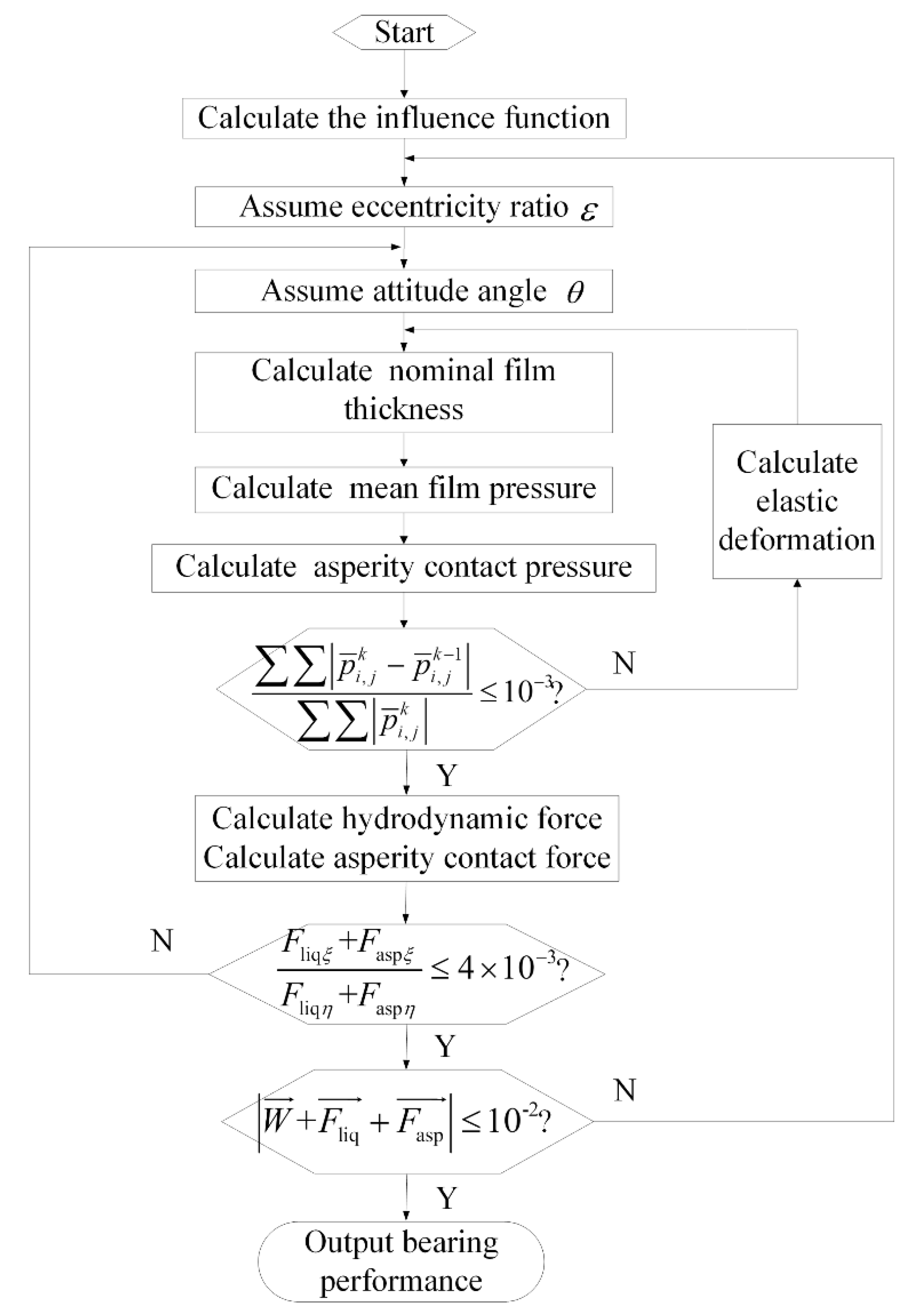
A numerical procedure is established via MATLAB R2022a software based on the proposed mixed lubrication model considering journal misalignment, local turbulence, and liner elastic deformation. The flowchart of the numerical procedure is shown in Figure 2. The eccentricity ratio and attitude angle are first assumed, and the water film thickness is calculated by Equation (2). In the initial calculation, the liner deformation u in Equation (2) is assumed to be zero. The local Reynolds number and lubrication regime of each node are determined according to the water film thickness at the node. Then, the mean pressure of the water film can be calculated by Equations (3) and (4), and the asperities contact pressure can be calculated by Equation (5). Next, the elastic deformation of each node can be calculated by using the obtained pressure. The elastic deformation is substituted into Equation (2) to calculate the new water film thickness. Then, the new mean pressure distribution can be obtained using the new film thickness. The process mentioned above is iterated until the mean pressure obtained by continuous calculation satisfies the pressure convergence condition. The hydrodynamic pressure and asperity contact force are calculated by Equations (6) and (7), respectively. Lastly, the attitude angle and eccentricity ratio are adjusted until the load balance condition is satisfied. The attitude angle can be adjusted according to θ j = θ j 1 α arctan ( F liq ξ + F asp ξ F liq η + F asp η ) (α is relaxation factor). The eccentricity ratio can be adjusted by comparing the resultant force of the bearing with the external load. The circumferential direction of the bearing is divided into 360 grids, and the grids for axial direction depend on the length–diameter ratio. For the bearings with a length–diameter ratio of two, the axial direction is divided into 160 grids. For 360 × 160 (circumferential direction × axial direction) rectangular meshes, the computational time for a typical test case (main parameters: journal diameter is 700 mm; length–diameter is 2.00; clearance ratio is 0.22%; elastic modulus of the liner is 4.4 × 10⁸ Pa; liner thickness is 20 mm and journal speed is 200 r/min) is approximately two hours.

3.2. Verification

The misaligned mixed lubrication bearing from [8] is numerically simulated using the proposed model to verify the numerical procedure. The bearing parameters are listed in Table 1. A typical value of the minimum film thickness-to-roughness ratio of the bearing is 1.75. The maximum hydrodynamic pressure obtained by the proposed model is listed in Table 2. The simulated and reference results are relatively similar. Accordingly, the accuracy of the proposed model in the analysis of misaligned mixed lubrication bearings has been verified.
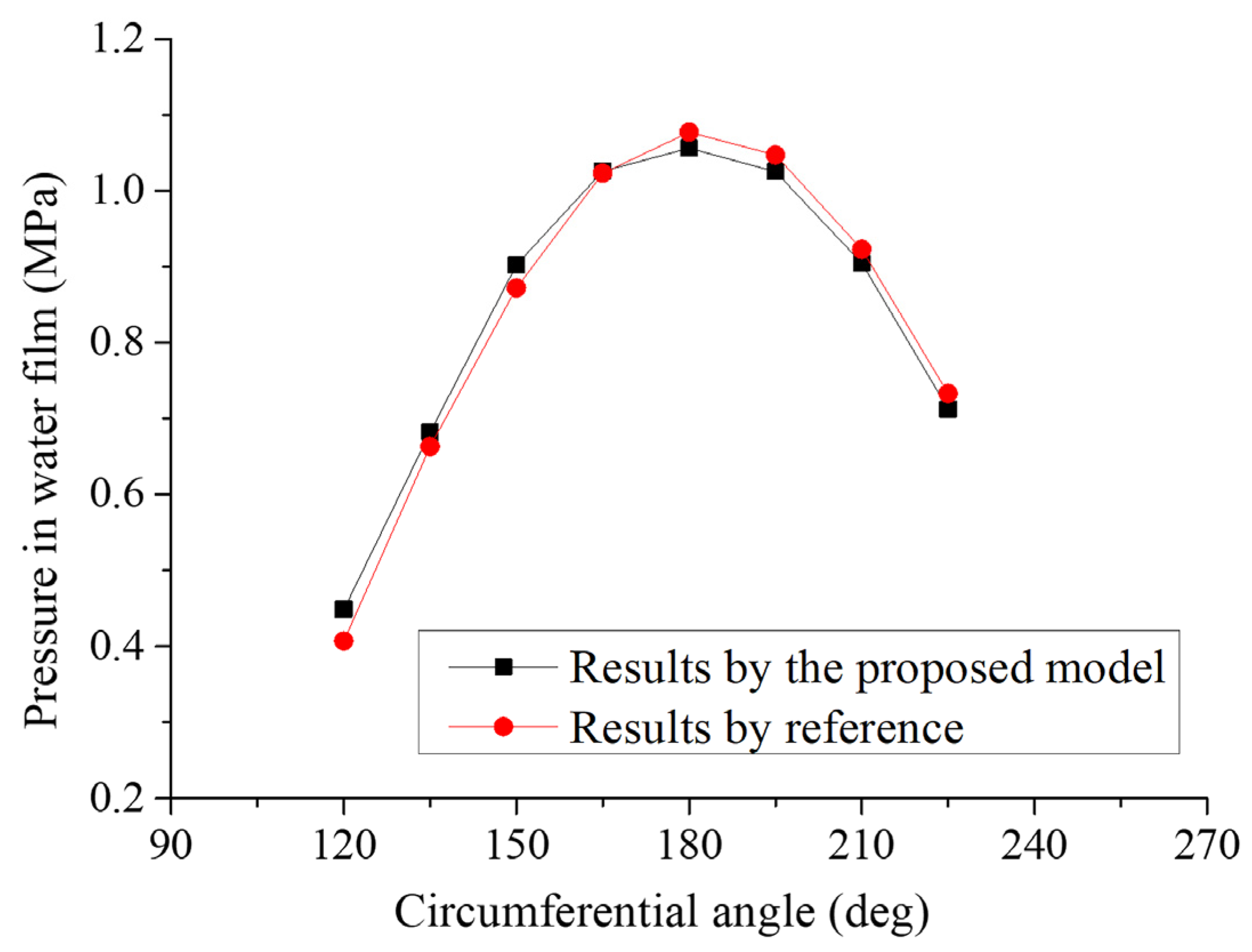
The proposed model’s accuracy in the turbulence lubrication analysis is validated by comparison with the experimental results in [31]. According to bearing parameters in [31], turbulent flow is locally generated when the journal speed is 660 r/min (the maximum local Reynolds number is 1188). The hydrodynamic pressure at the measuring point was obtained in [31]. The mean hydrodynamic pressure of the bearing with the same parameters is numerically calculated via the proposed model. As shown in Figure 3, the numerical calculation results are consistent with experimental results from [31].

4. Results and Discussion

In this section, the influence of key structural and operating parameters on the performance of misaligned water-lubricated bearings is analyzed. The basic bearing parameters are listed in Table 3. As shown in Figure 1a, the bearing has nine grooves.

4.1. The influence of the Length-Diameter Ratio

Generally, the journal diameter is determined by the shaft’s design. Selecting the length–diameter ratio of the bearing is selecting the bearing’s effective working length. The lubrication characteristics of bearings with the misalignment angle of 0.025 mrad and the length–diameter ratio of one and two are analyzed. The remaining bearing parameters remain unchanged (listed in Table 3). As a comparison, the lubrication characteristics of the corresponding bearing without journal misalignment are also given.
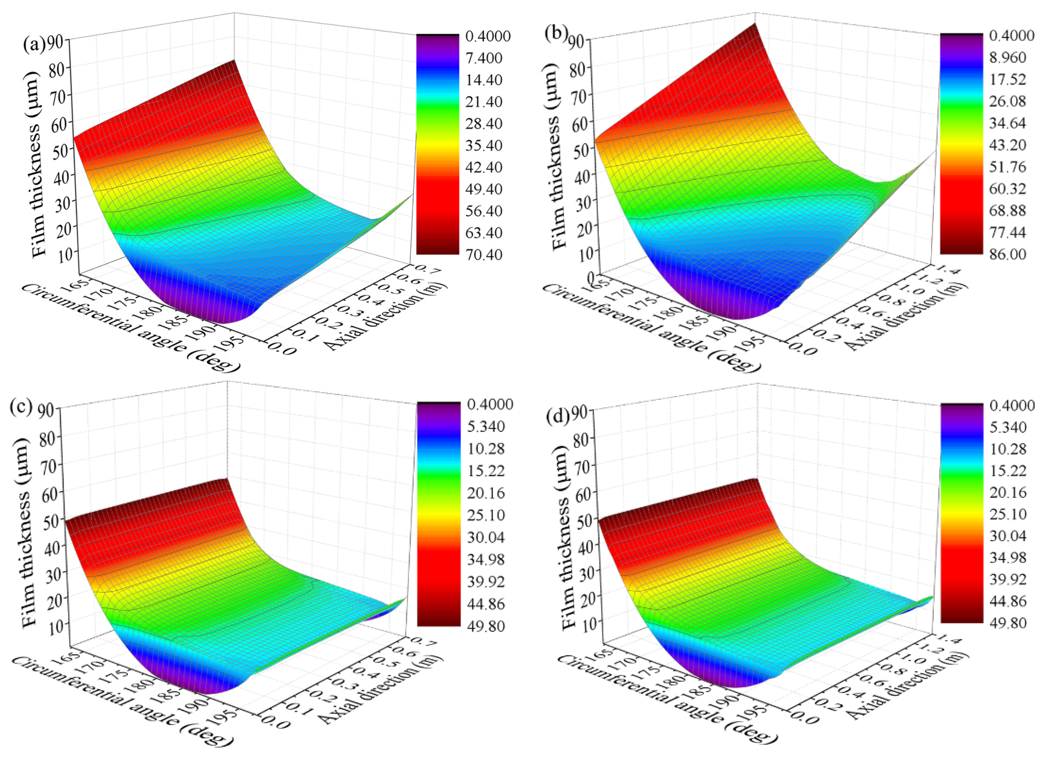
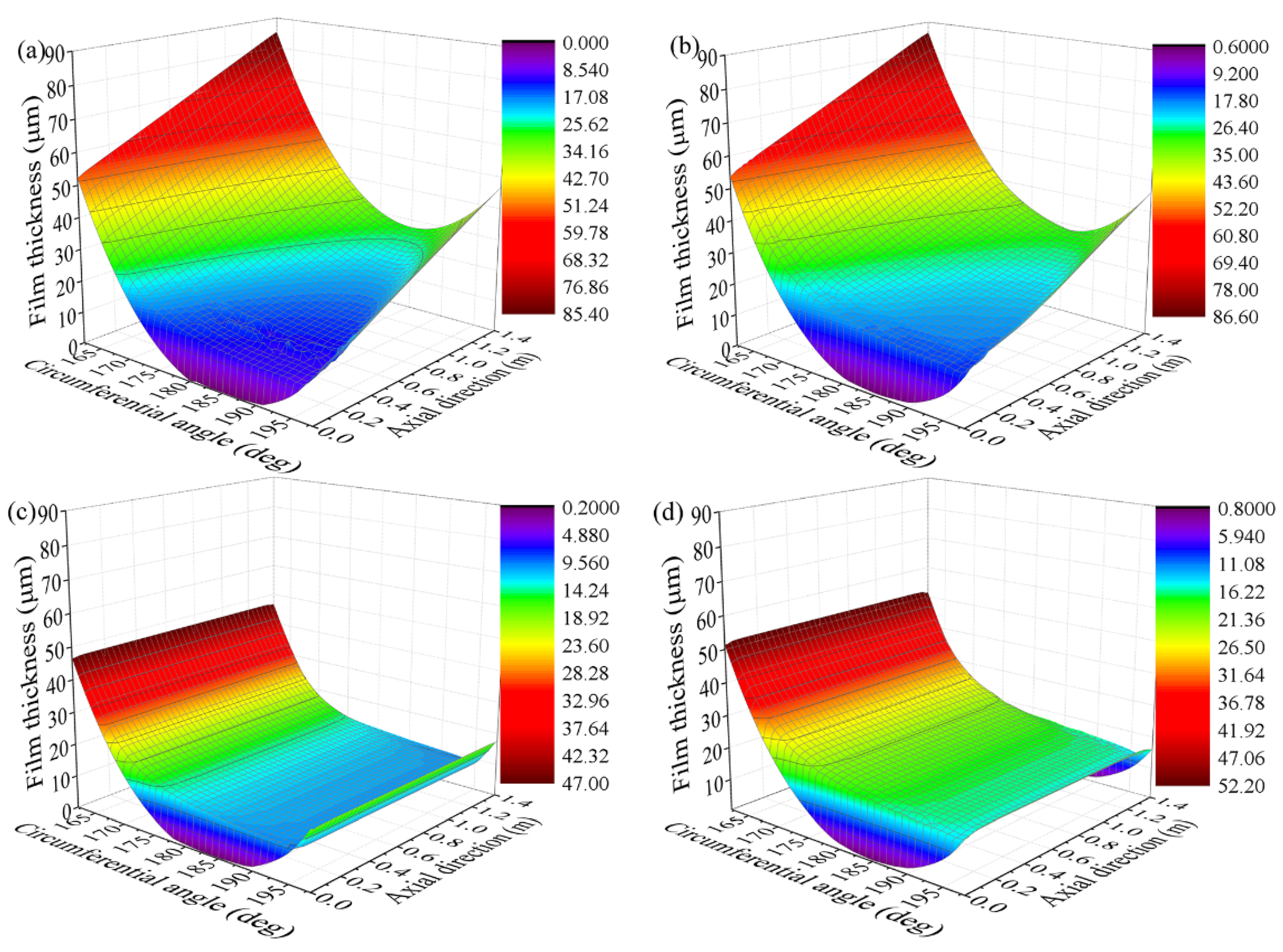
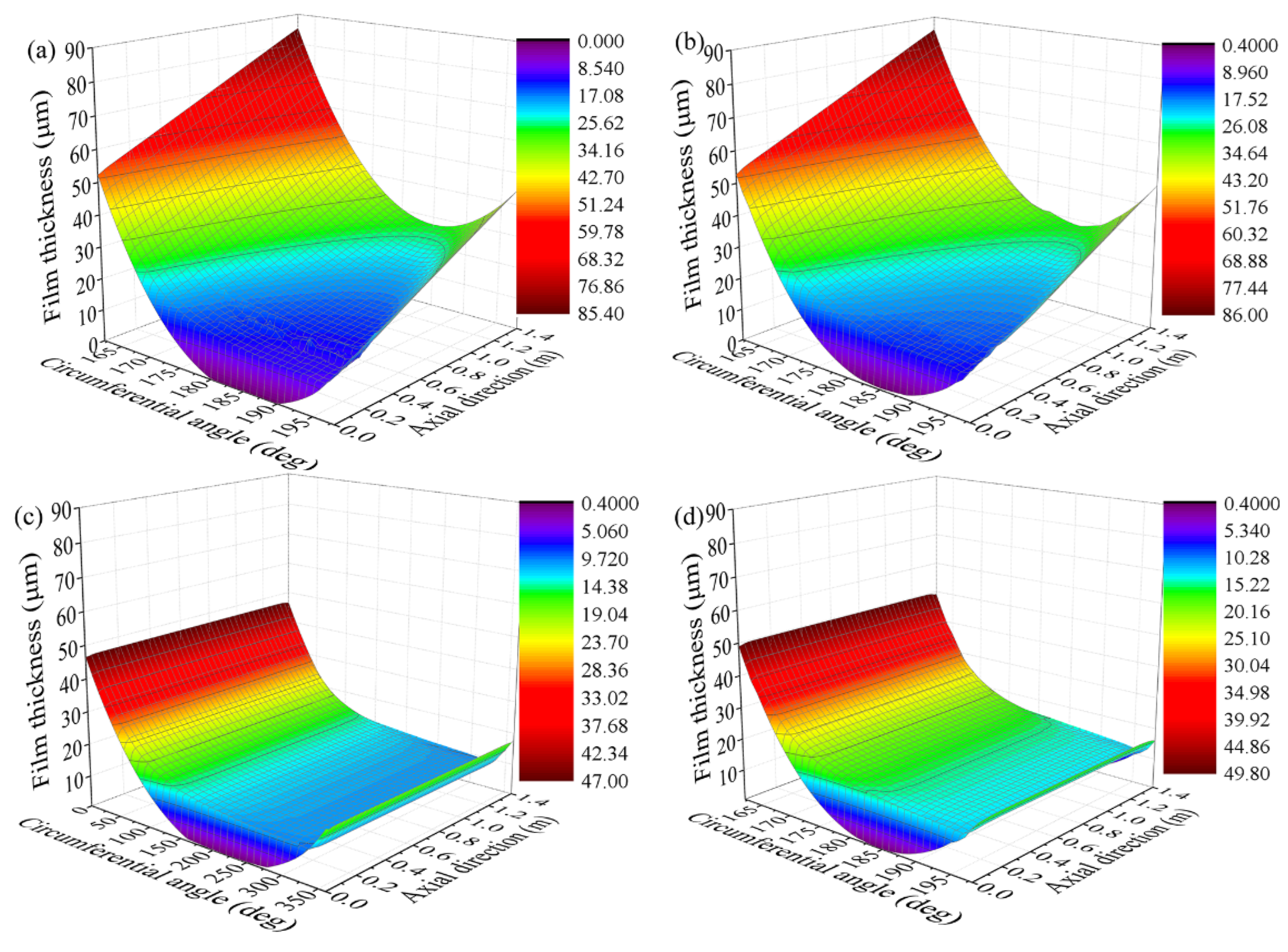
Figure 4 shows the nominal film thickness distribution of the bearing versus length–diameter ratio. The water film thickness is uniformly distributed along the axial direction for the aligned bearing. As the water film pressure at the axial ends decreases to zero, the resulting liner deformation is small, resulting in a minimum film thickness at two axial ends. For the misaligned bearing, the water film thickness varies greatly along the axial direction, and the minimum film thickness is located at the journal down-warping end. The water film’s lubrication regime depends on the nominal film thickness ratio to roughness. Therefore, the axial non-uniform water film thickness distribution results in different axial bearing sections in various lubrication regimes. The area with a film thickness-to-roughness ratio higher than three is in a pure hydrodynamic lubrication regime, while the area with a ratio of film thickness to roughness less than three is in a mixed lubrication regime. According to Figure 4a,b, when the journal is misaligned and the journal down-warping end has the same eccentricity, the minimum nominal film thickness does not change significantly when the length–diameter ratio increases. The minimum film thickness at the journal up-warping end with a relatively small length–diameter ratio is lower than that with a relatively large length–diameter ratio.
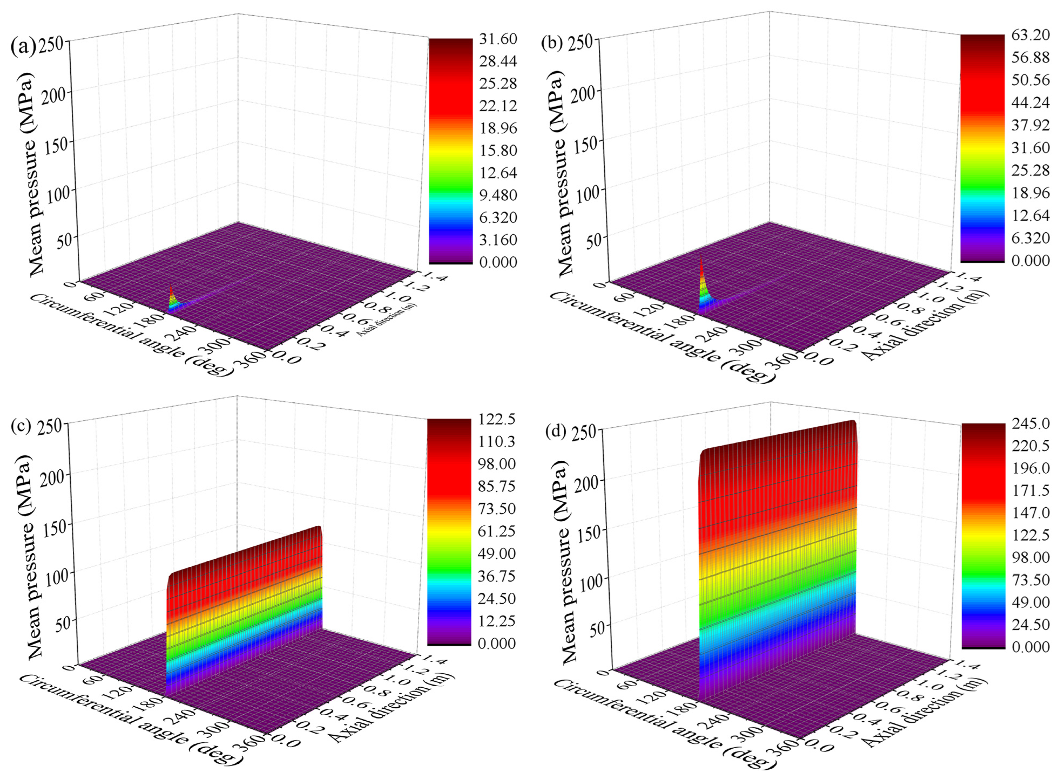
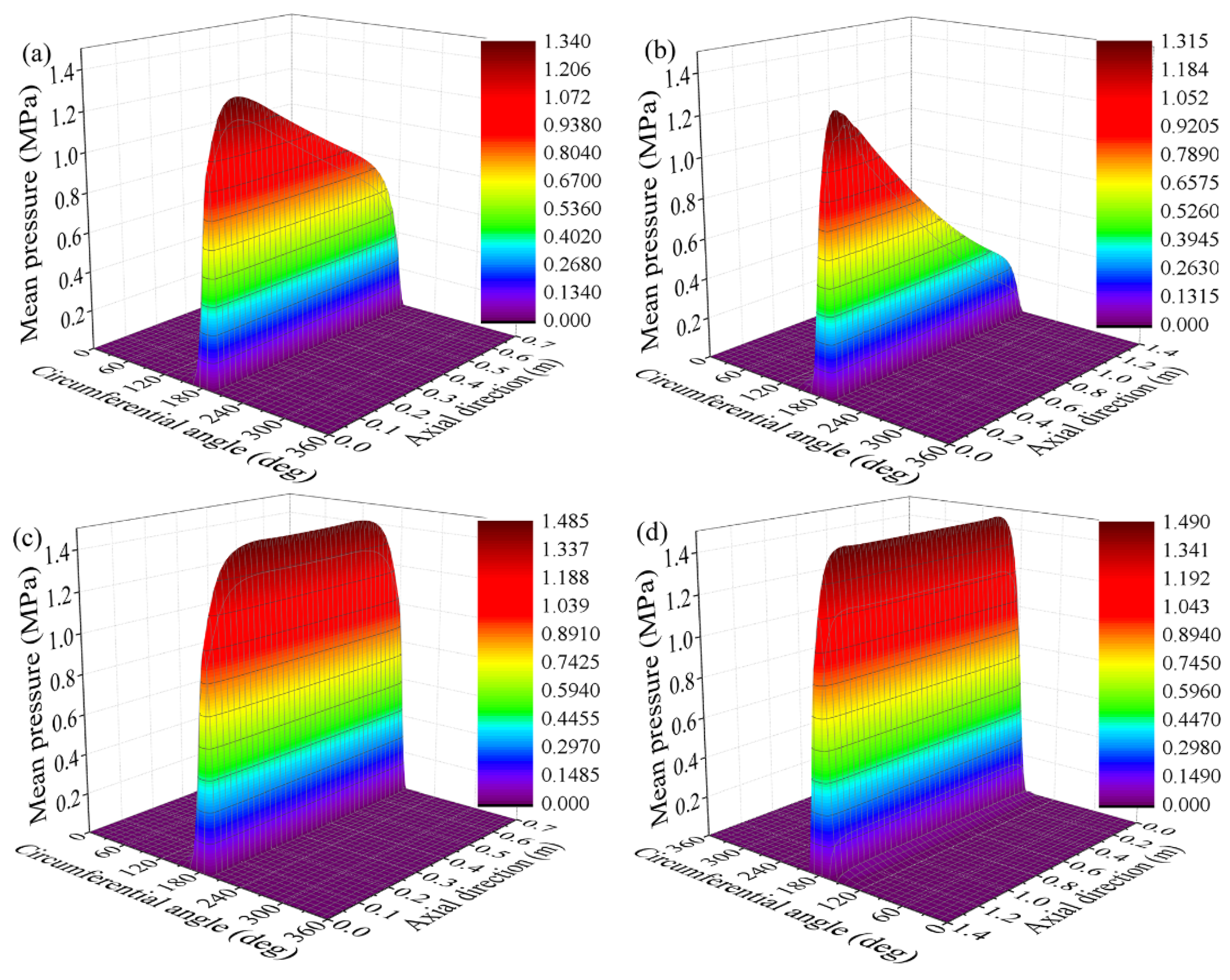
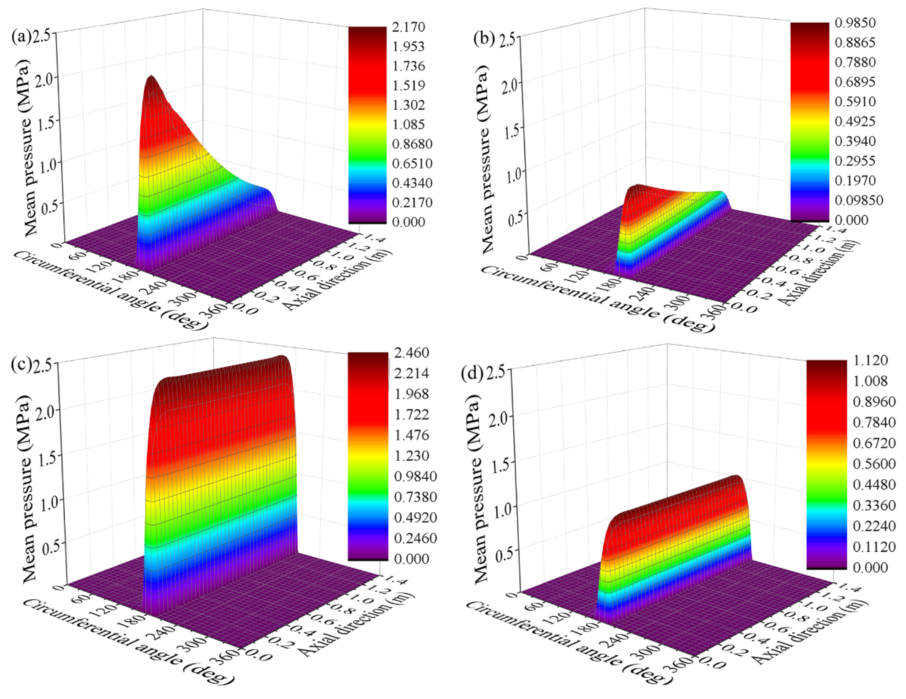
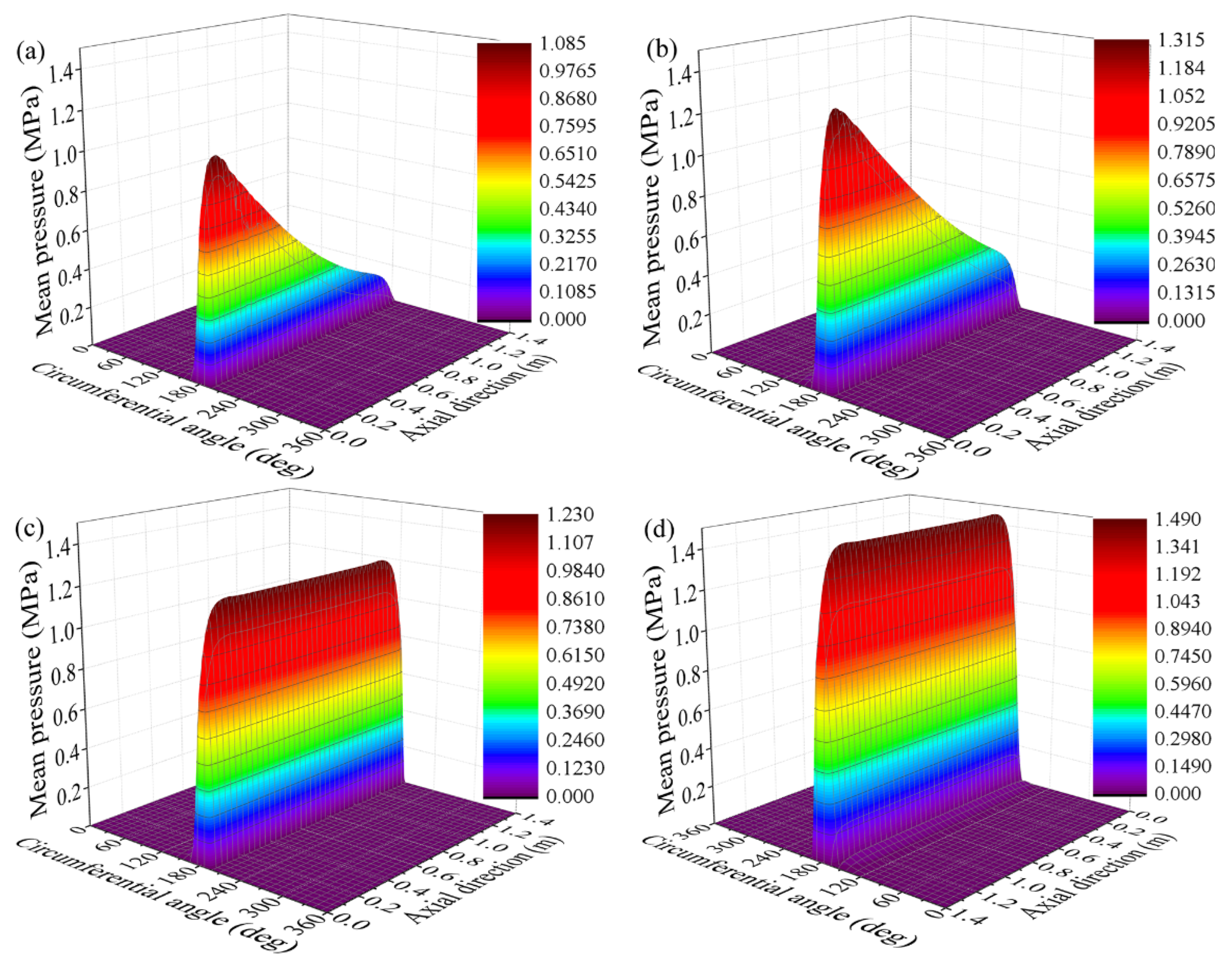
The mean hydrodynamic pressure of the bearing for various length–diameter ratios is shown in Figure 5. It can be observed that the main load-carrying area of the bearing is the area between groove five and groove six (the corresponding circumferential angle ranges from 162° to 198°), which is at the bottom of the bearing. For the aligned bearing, water film pressure is symmetrically distributed along the axial direction. When the eccentricity ratio is constant, the change in length–diameter ratio minorly affects the maximum hydrodynamic pressure of the aligned bearing. The water film pressure distribution is asymmetric in the axial direction for the misaligned bearing. The maximum mean hydrodynamic pressure is close to the journal down-warping end. With an increase in the length–diameter ratio, the uniformity of the axial distribution of the hydrodynamic pressure is greatly reduced.
The lubrication characteristics of bearings with different length–diameter ratios are listed in Table 4. Compared with the aligned bearing, the load-carrying capacity is significantly reduced, and the bearing friction coefficient is significantly increased when the journal is misaligned, indicating that the journal misalignment significantly worsens the bearing lubrication characteristics. With an increase in the length–diameter ratio for aligned bearings, the rate of increase for the load-carrying capacity is slightly greater than that of the length–diameter ratio. This is because the increase in length–diameter ratio decreases end leakage, which is conducive to enhancing the hydrodynamic pressure. When the journal is misaligned, the rate of increase of load-carrying capacity caused by increasing the length–diameter ratio is far less than for the aligned bearing. The load-carrying capacity of a misaligned bearing is no longer approximately linear with the length–diameter ratio. Therefore, for misaligned bearings, the load-carrying capacity cannot be only improved by increasing the length–diameter ratio in bearing design.

4.2. The influence of the Liner Thickness

For polymer bearings, the change in the liner thickness significantly impacts the static and dynamic characteristics of the bearing but not its overall size. Therefore, designers can implement liner thickness as an important variable parameter in the design of the optimal bearing. The lubrication characteristics of bearings with a misalignment angle of 0.025 mrad and a liner thickness of 10 mm, 20 mm, and 30 mm are analyzed. The remaining parameters of the bearing remain unchanged (listed in Table 3). For comparison, the lubrication characteristics of the corresponding bearing without journal misalignment are also provided.
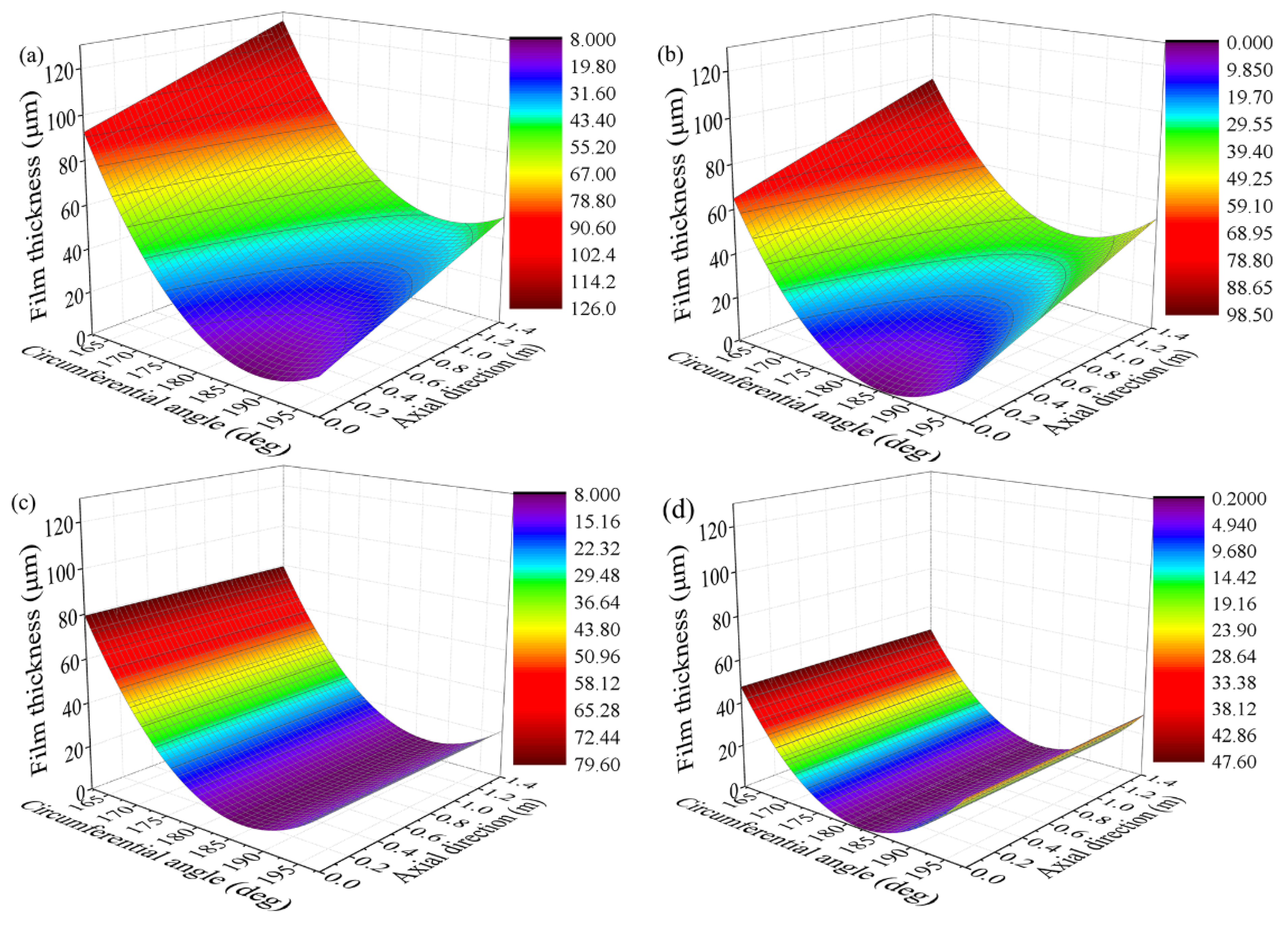
Figure 6 shows the nominal film thickness distribution of the bearing with different liner thicknesses. The minimum nominal film thickness increases with liner thickness for the same eccentricity ratio. This can be attributed to an increase in the liner’s elastic deformation with its thickness.
Figure 7 shows the mean hydrodynamic pressure distribution of the bearing with different liner thicknesses. With an increase in the liner thickness, the maximum hydrodynamic pressure decreases significantly due to an increase in the water film thickness. The axial uniformity of hydrodynamic pressure distribution of misaligned bearing improves significantly with an increase in the liner thickness.
Bearing characteristics with different liner thicknesses are listed in Table 5. For aligned bearings under constant eccentricity, the load-carrying capacity of the bearing significantly decreases with an increase in liner thickness. For misaligned bearings, when the liner thickness increases, the decline of load-carrying capacity caused by journal misalignment decreases because the thicker liner improves the uniformity of the pressure distribution in the axial direction.
According to the above analysis, an increase in the liner thickness reduces the load-carrying capacity when the journal is aligned and improves the pressure distribution uniformity in the axial direction when the journal is misaligned. This feature can be used to adjust the pressure distribution of the bearing during the bearing design. Furthermore, selecting a liner with a relatively low elastic modulus can be inferred to improve the uniformity of pressure distribution of a bearing with journal misalignment.

4.3. The Influence of the Clearance Ratio

The change in the clearance ratio greatly impacts the bearing characteristics but does not affect the overall size of the bearing. Therefore, designers often consider the clearance ratio an important parameter in bearing design optimization. Moreover, adjusting the clearance ratio is also an effective way to improve bearing running performance and deal with bearing faults. The lubrication characteristics of bearings with misalignment angle of 0.025 mrad and clearance ratios of 0.17%, 0.22%, and 0.28% are analyzed. The remaining bearing parameters remain unchanged (listed in Table 3). As a comparison, the lubrication characteristics of the corresponding bearing without journal misalignment are also provided.
Figure 8 shows the distribution of the nominal film thickness of the bearing with different clearance ratios. For the same eccentricity ratio, the minimum nominal film thickness decreases with an increase in the clearance ratio, which is contrary to the rule of ordinary bearings. This is because the eccentricity ratio of the bearing is greater than one. The elastic modulus of the polymer liner is significantly lower than that of the metal bearing. Liner’s elastic deformation makes the bearing often operate with eccentricity ratios greater than one.
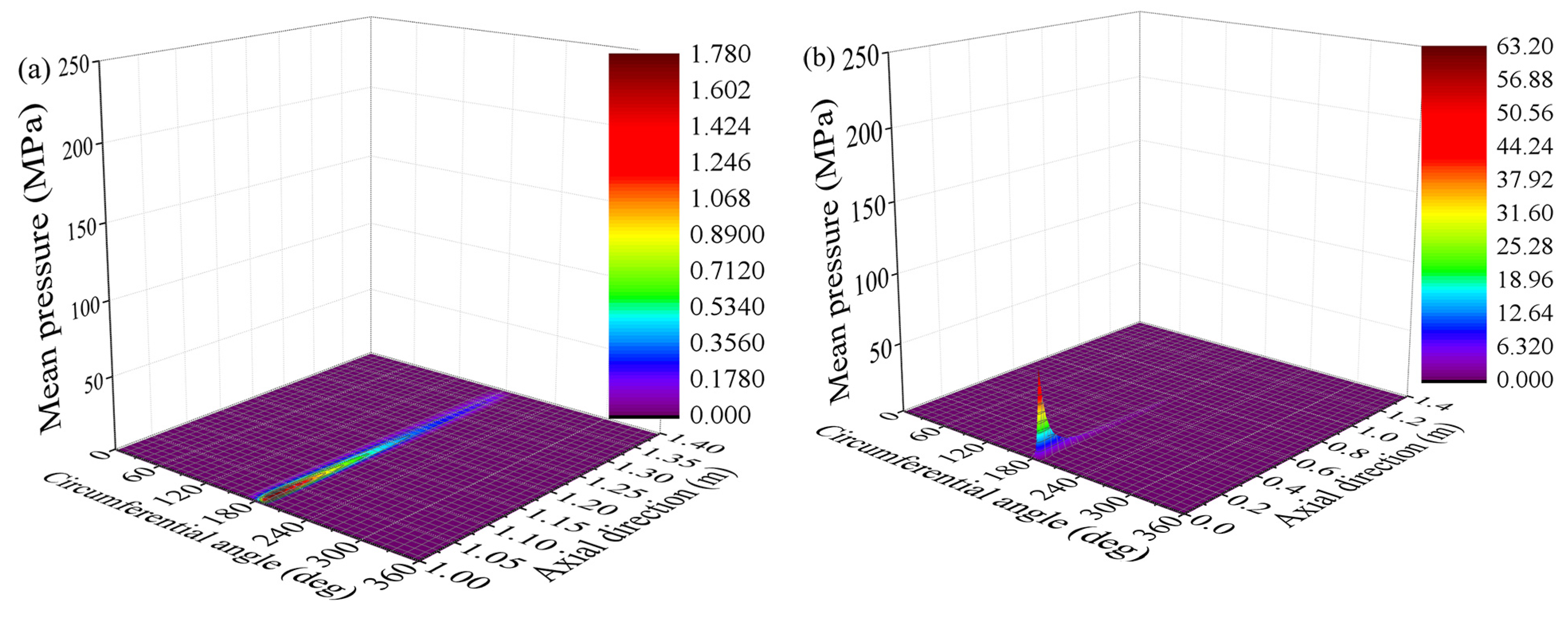
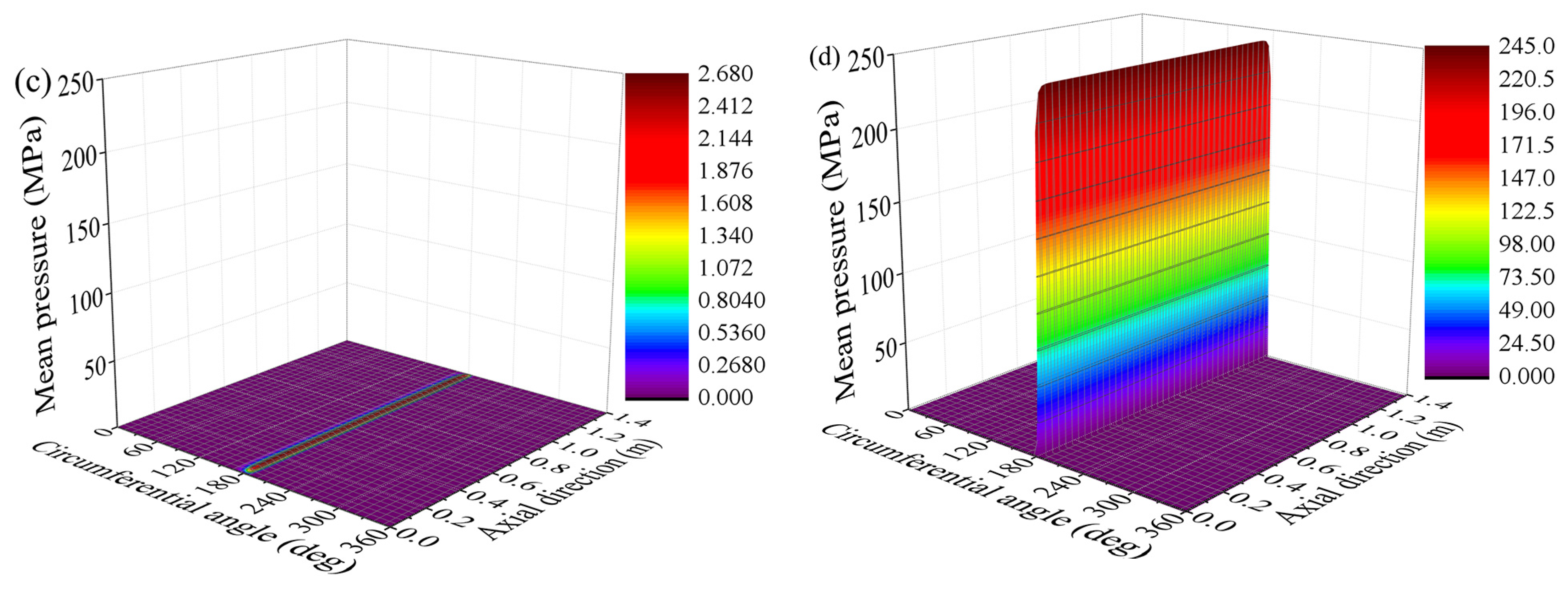
Figure 9 shows the mean hydrodynamic pressure distribution of the bearing with different clearance ratios. For the same eccentricity ratio, the maximum mean hydrodynamic pressure increases with the clearance ratio. This is because the minimum film thickness of the bearing with a relatively large clearance ratio is smaller, causing the hydrodynamic pressure to rise more rapidly. For a misaligned bearing, the area with relatively high hydrodynamic pressure decreases with an increase in the clearance ratio; hence, the non-uniformity of the pressure increases.
Table 6 lists the bearing characteristics with different clearance ratios. When the eccentricity ratio is larger than one, the load-carrying capacity decreases slightly, and the friction coefficient increases remarkably with an increase in the clearance ratio. Accordingly, an excessive clearance ratio should not be selected in bearing design prone to the mixed lubrication regime.

4.4. The Influence of Journal Speed

Lubrication characteristics of bearings with a misalignment angle of 0.025 mrad at journal speeds of 100 r/min and 200 r/min are analyzed. The remaining bearing parameters are unchanged (listed in Table 3). The lubrication characteristics of the corresponding bearing without journal misalignment are also provided for comparison.
Figure 10 shows the nominal film thickness distribution of the bearing at different journal speeds. Under the same eccentricity ratio, the minimum film thickness slightly increases with the journal speed. This is because the hydrodynamic pressure of the bearing increases with the journal speed, which increases the liner elastic deformation. Figure 11 shows the mean hydrodynamic pressure distribution of the bearing at different journal speeds. The journal speed increases the hydrodynamic effect, increasing the hydrodynamic pressure.
Table 7 lists the bearing characteristics at different journal speeds. The load-carrying capacity increases with the journal speed, which is consistent with the law of rigid bearings. However, due to the elastic deformation of the polymer liner, an increase in the load-carrying capacity caused by an increase in the journal speed is smaller than that of rigid bearing (see the Appendix A for calculation results of a rigid bearing). The friction coefficient of the bearing decreases with an increase in the journal speed. This is because the bearing at a relatively high speed has relatively large hydrodynamic pressure under the same eccentricity ratio. Thus, the liner elastic deformation increases, which reduces the friction caused by the asperity contact.

4.5. The Influence of the Eccentricity Ratio

When the other bearing parameters are constant, the eccentricity ratio change represents the specific pressure and load change. Due to the liner’s elastic deformation, the eccentricity ratio of water-lubricated bearings under heavy load conditions is often greater than one. The lubrication characteristics of bearings with a misalignment angle of 0.025 mrad and eccentricity ratios of 1.00 and 1.01 are analyzed. The remaining bearing parameters remain unchanged (listed in Table 3). For comparison, the lubrication characteristics of the corresponding bearing without journal misalignment are also provided.
Figure 12 shows the nominal film thickness distribution of bearings with eccentricity ratios of 1.00 and 1.01. The minimum nominal film thickness decreases with an increase in the eccentricity ratio. The elastic deformation of the polymer liner causes the minimum nominal film thickness change less than the eccentricity change. Therefore, the liner’s elastic deformation weakens the dependence of minimum nominal film thickness on eccentricity. Figure 13 shows the bearings’ mean hydrodynamic pressure distribution with eccentricity ratios of 1.00 and 1.01. An increased eccentricity enhances the wedge effect in the load-carrying area, thus increasing the maximum mean hydrodynamic pressure.
Bearing characteristics with different eccentricity ratios are listed in Table 8. It can be observed that the load-carrying capacity increases with the eccentricity ratio. However, due to the liner’s elastic deformation, an increase in the load-carrying capacity with the eccentricity ratio is lower than that of rigid bearings (see the Appendix A for calculation results of a rigid bearing). The friction force caused by asperity contact increases as the minimum nominal film thickness decreases with an increase in eccentricity. Thus, the friction coefficient of the bearing increases significantly. For misaligned bearings, the reduction proportion of load-carrying capacity caused by journal misalignment decreases when the eccentricity ratio increases. Hence, the effect of journal misalignment on lubrication performance for polymer bearings is weakened when the load increases.

5. Conclusions

In this paper, a mixed lubrication model for water-lubricated polymer bearing was established considering the effect of journal misalignment, liner elastic deformation, and local turbulence. The influence of key structural and operating parameters on the performance of misaligned water-lubricated bearings was investigated. The main conclusions are as follows:
(1)
Journal misalignment significantly reduces the load-carrying capacity of the bearing, deteriorates its tribological characteristics, and may cause different axial sections of the bearing to be in different lubrication regimes.
(2)
For misaligned bearings, the load-carrying capacity is no longer proportional to the length–diameter ratio. The rate of increase of load-carrying capacity decreases with an increase in the length–diameter ratio. Therefore, the load-carrying capacity cannot be effectively increased for misaligned bearings by blindly increasing the length–diameter ratio during bearing design.
(3)
When the journal is misaligned, the increase in liner thickness can improve the axial uniformity of hydrodynamic pressure distribution. Therefore, the bearing pressure distribution can be improved by adjusting liner thickness during the bearing design. Selecting a liner with a relatively low elastic modulus can be inferred to improve the uniformity of pressure distribution of a bearing with journal misalignment.
(4)
The reduction proportion of load-carrying capacity caused by journal misalignment decreases when the eccentricity ratio increases. Accordingly, when the load increases, the influence of journal misalignment on bearing performance and axial nonuniform degree of bearing pressure distribution are both weakened for polymer bearings.
(5)
With an increase in the clearance ratio, the load-carrying capacity of misaligned bearing decreases slightly while the friction coefficient and the non-uniformity of the pressure increase significantly. Therefore, an excessive clearance ratio should not be selected in bearing design prone to the mixed lubrication regime.
The experimental research on misaligned water-lubricated bearings with different structural and operating parameters will be addressed in future work. Moreover, research on misaligned water-lubricated bearings under unsteady conditions will be carried out.

Author Contributions

Conceptualization, F.L.; methodology, F.L.; software, F.L.; validation, C.J. and F.L.; formal analysis, C.J. and Q.J.; investigation, F.L. and C.J.; resources, F.L.; data curation, F.L. and C.J.; writing—original draft preparation, F.L.; writ-ing—review and editing, C.J. and K.X.; visualization, F.L. and Q.J.; supervision, Q.J.; project administration, F.L.; funding acquisition, F.L. All authors have read and agreed to the published version of the manuscript.

Funding

This research was funded by National Natural Science Foundation of China (grant number 12002117) and Changzhou Sci&Tech Program (grant number CJ20200072).

Data Availability Statement

Data is contained within the article or Appendix A.

Acknowledgments

The authors gratefully acknowledge the financial supports of this study by the National Natural Science Foundation of China (Grant no. 12002117) and Changzhou Sci&Tech Program (Grant no. CJ20200072).

Conflicts of Interest

The authors declare no conflict of interest.

Appendix A

A rigid bearing with different operating parameters is compared with the calculation results of bearings with elastic liners. The basic bearing parameters are listed in Table A1. For rigid bearings, the eccentricity ratio can only be lower than one. The bearing eccentricity ratio in this part is taken as 0.9995 to ensure that the minimum film thickness is close to the calculation cases in Section 4.
Table A1. Parameters of the rigid bearing.
ParameterValueParameterValue
Journal diameter (mm)700Length–diameter ratio2
Clearance ratio0.22%Groove number9
Groove angle (°)4Contact friction coefficient0.2
Liner surface roughness (μm)2.4Journal surface roughness (μm)0.8
Rated speed (rpm)200Eccentricity ratio0.9995
Lubrication characteristics of bearings with a misalignment angle of 0.025 mrad at journal speeds of 100 r/min and 200 r/min are analyzed. The remaining bearing parameters are unchanged (listed in Table A1). The lubrication characteristics of the corresponding bearing without journal misalignment are also provided.
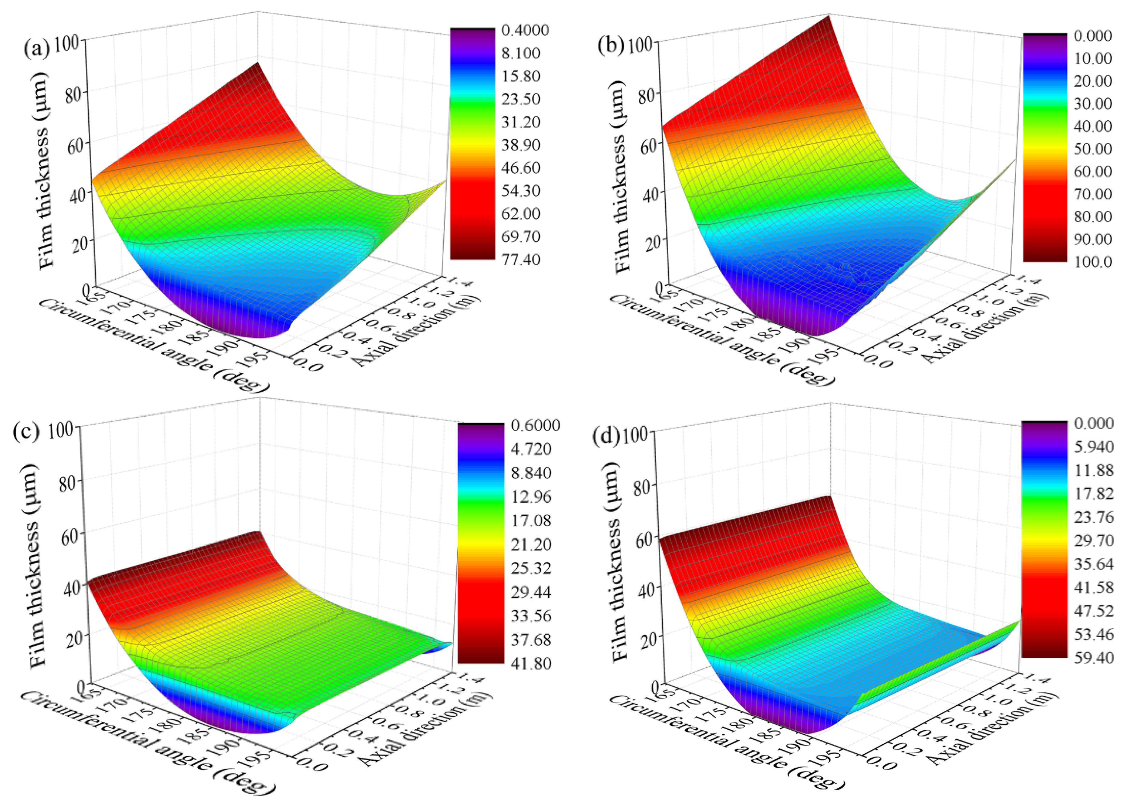
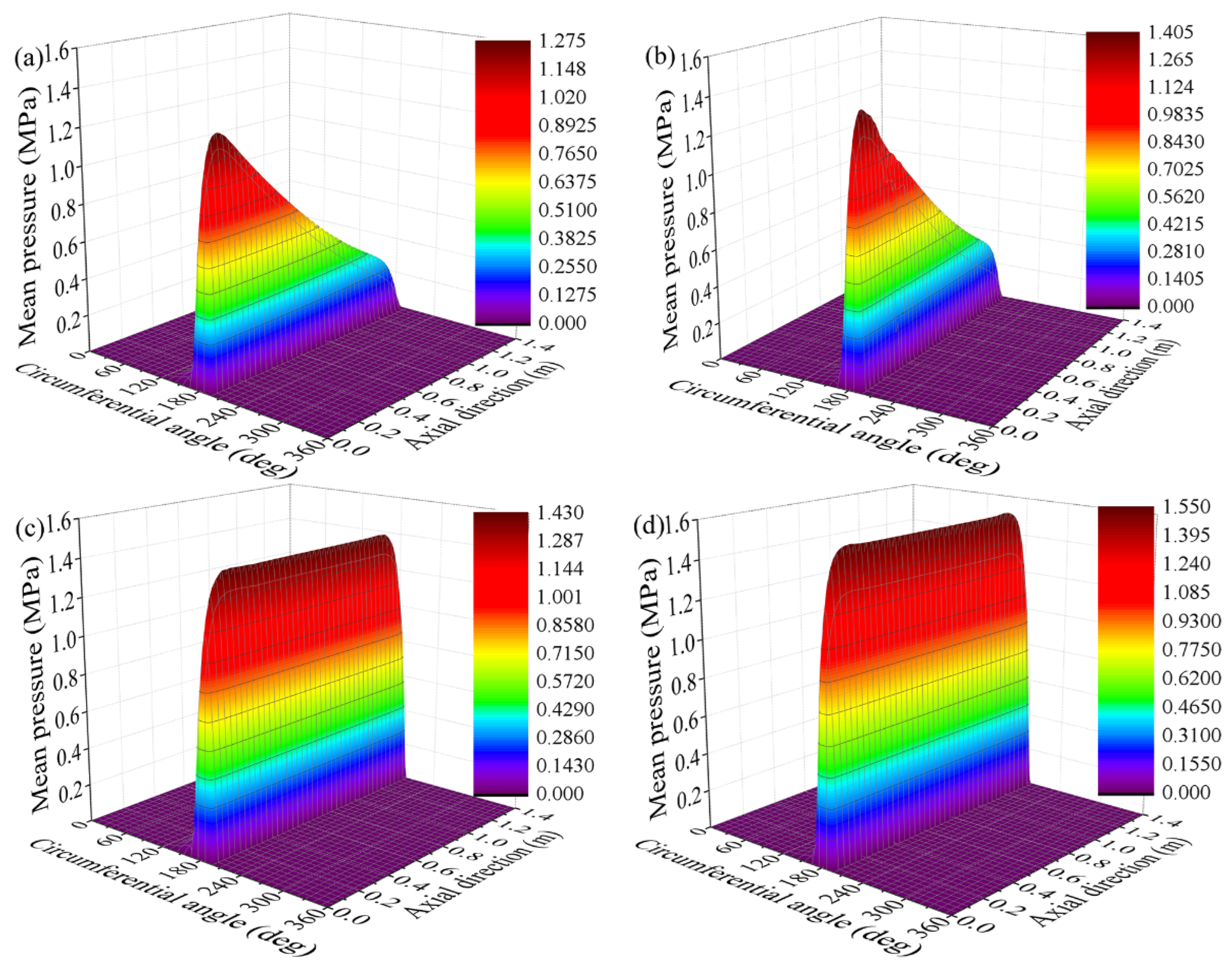
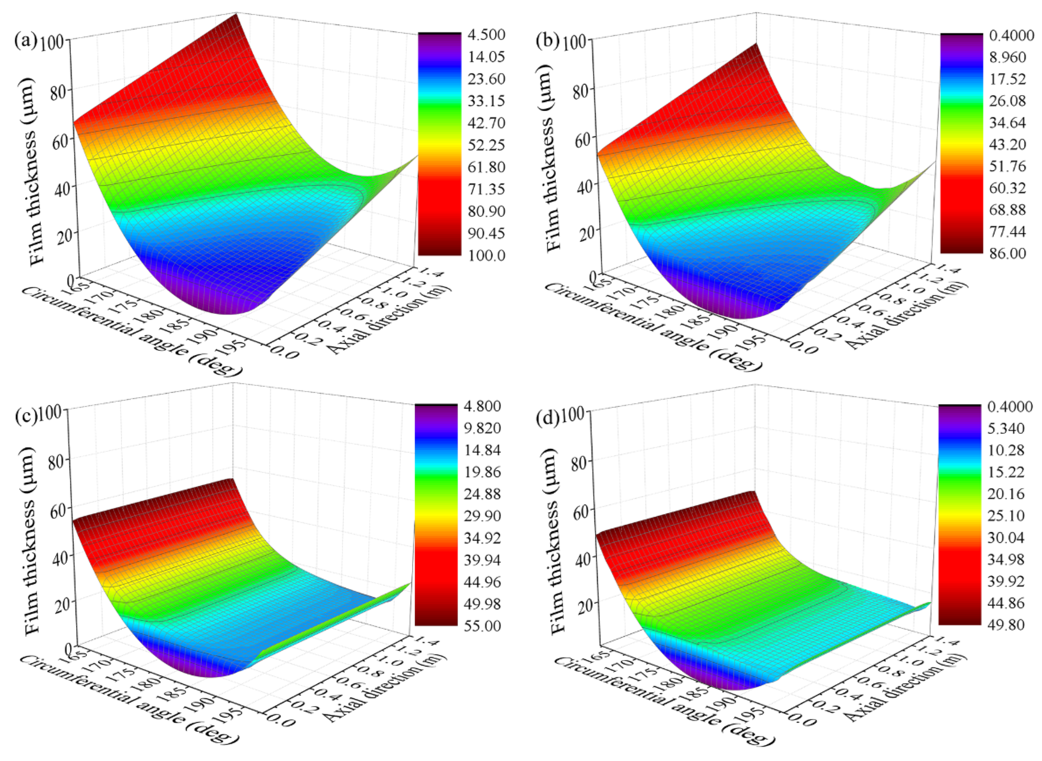
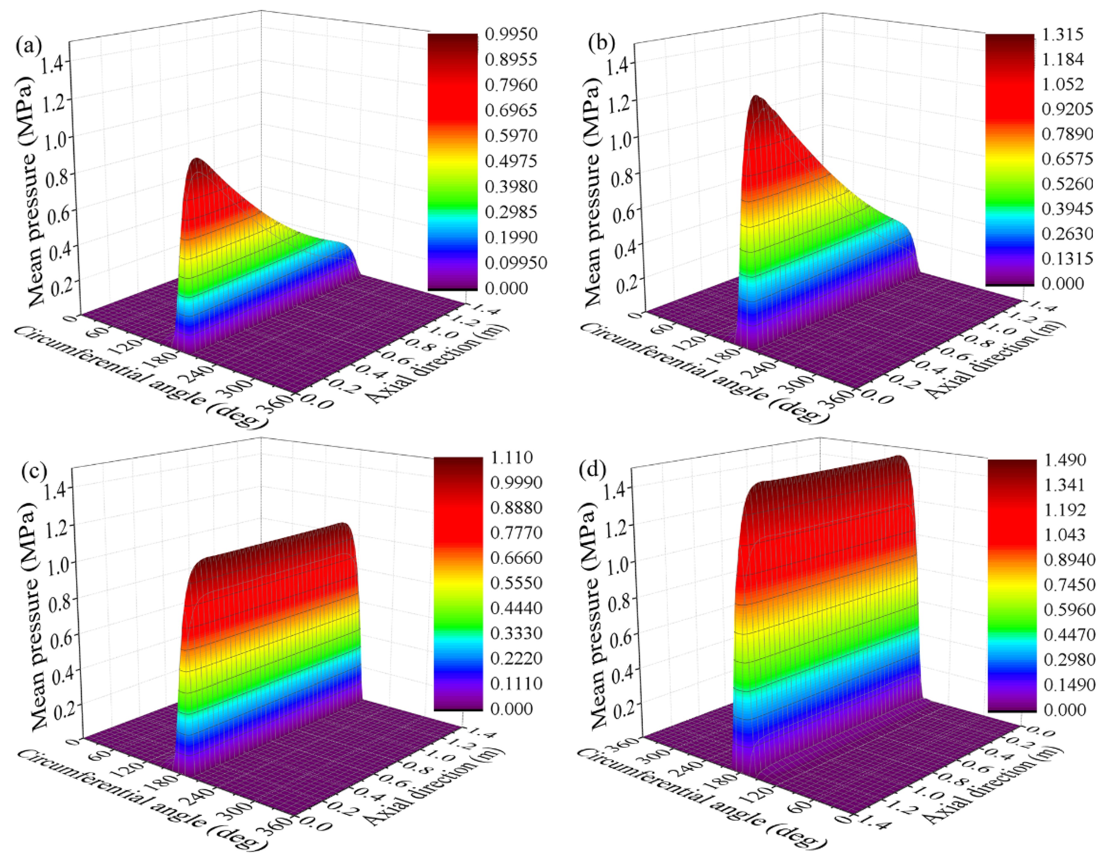
Figure A1 shows the nominal film thickness distribution of the bearing at different journal speeds. Under the same eccentricity ratio, the minimum film thickness remains constant with an increase in the journal speed. Figure A2 shows the mean hydrodynamic pressure distribution of the bearing at different journal speeds. The journal speed increases the hydrodynamic effect, remarkably increasing the hydrodynamic pressure.
Figure A1. The film thickness distributions of the rigid bearing versus journal speeds: (a) misaligned bearing with journal speed of 100 r/min; (b) misaligned bearing with journal speed of 200 r/min; (c) aligned bearing with journal speed of 100 r/min; (d) aligned bearing with journal speed of 200 r/min.
Lubricants 10 00336 g0a1
Figure A2. Pressure distributions of the rigid bearing versus journal speeds: (a) misaligned bearing with journal speed of 100 r/min; (b) misaligned bearing with journal speed of 200 r/min; (c) aligned bearing with journal speed of 100 r/min; (d) aligned bearing with journal speed of 200 r/min.
Lubricants 10 00336 g0a2
Table A2 lists the bearing characteristics at different journal speeds. The load-carrying capacity significantly increases with the journal speed. The increase in the load-carrying capacity with the journal speed is higher than that of bearings with elastic liner.
Table A2. Characteristics of the rigid bearing versus journal speeds.
Attitude Angle (°)Load-Carrying Capacity (kN)Friction Force (N)Friction Coefficient
Bearing with the rotational speed of 100 r/min and γ = 0.025 mrad5.62115.6200.20.00173
Bearing with the rotational speed of 200 r/min and γ = 0.025 mrad5.62230.6263.50.00114
Aligned bearing with the rotational speed of 100 r/min2.163128.53825.70.00122
Aligned bearing with the rotational speed of 200 r/min2.166239.74196.90.00067
The lubrication characteristics of bearings with misalignment angle of 0.025 mrad and eccentricity ratios of 0.9895 and 0.9995 are analyzed. The remaining bearing parameters are unchanged (listed in Table A1). The lubrication characteristics of the corresponding bearing without journal misalignment are also provided.
Figure A3 shows the distribution of the nominal film thickness of the bearing with different eccentricity ratios. The minimum nominal film thickness significantly decreases with an increase in the clearance ratio. The rate of decrease for the minimum nominal film thickness is much higher than that of bearings with elastic liner. Figure A4 shows the mean hydrodynamic pressure distribution of the bearing with different eccentricity ratios. The maximum mean hydrodynamic pressure increases with the eccentricity ratio. The rate of increase for the maximum mean hydrodynamic pressure is much higher than that of bearings with elastic liner.
Figure A3. Lubricating film thickness distributions of the rigid bearing versus eccentricity ratios: (a) misaligned bearing with ε = 0.9895; (b) misaligned bearing with ε = 0.9995; (c) aligned bearing with ε = 0.9895; (d) aligned bearing with ε = 0.9995.
Lubricants 10 00336 g0a3
Figure A4. Film pressure distributions of the rigid bearing versus eccentricity ratios: (a) misaligned bearing with ε = 0.9895; (b) misaligned bearing with ε = 0.9995; (c) aligned bearing with ε = 0.9895; (d) aligned bearing with ε = 0.9995.
Lubricants 10 00336 g0a4aLubricants 10 00336 g0a4b
Bearing characteristics with different eccentricity ratios are listed in Table A3. It can be observed that the load-carrying capacity increases with the eccentricity ratio. The increase in the load-carrying capacity with the eccentricity ratio is much higher than that of bearings with elastic liner.
Table A3. Characteristics of the rigid bearing versus eccentricity ratios.
Attitude Angle (°)Load-Carrying Capacity (kN)Friction Force (N)Friction Coefficient
Bearing with ε = 0.9895 and γ = 0.025 mrad9.2275.386.30.00115
Bearing with ε = 0.9995 and γ = 0.025 mrad5.62230.6263.50.00114
Aligned bearing with ε = 0.98956.99246.8154.50.00063
Aligned bearing with ε = 0.99952.166239.74196.90.00067

References

  1. Wodtke, M.; Litwin, W. Water-lubricated stern tube bearing—Experimental and theoretical investigations of thermal effects. Tribol. Int. 2021, 153, 106608. [Google Scholar] [CrossRef]
  2. Litwin, W. Marine propeller shaft bearings under low-speed conditions: Water vs. oil lubrication. Tribol. Trans. 2019, 62, 839. [Google Scholar] [CrossRef]
  3. Han, Y.; Yin, L.; Xiang, G.; Zhou, G.; Zheng, X. An experimental study on the tribological performance of water-lubricated journal bearings with three different materials. Ind. Lubr. Tribol. 2020, 72, 1159–1165. [Google Scholar] [CrossRef]
  4. Lin, C.; Zou, M.; Sima, C.; Liu, S.; Jiang, L. Friction-induced vibration and noise of marine stern tube bearings considering perturbations of the stochastic rough surface. Tribol. Int. 2019, 131, 661–671. [Google Scholar] [CrossRef]
  5. Zhang, Z.; Dai, X.; Xie, Y. Thermoelastohydrodynamic behavior of misaligned plain journal bearings. Proc. Inst. Mech. Eng. Part C J. Mech. Eng. Sci. 2013, 227, 2582–2599. [Google Scholar] [CrossRef]
  6. Litwin, W.; Michał, W.; Artur, O. Shaft misalignment influence on water lubricated turbine sliding bearing with various bush module of elasticity. Key Eng. Mater. 2012, 90, 128–134. [Google Scholar] [CrossRef]
  7. Mallya, R.; Shenoy, S.B.; Pai, R. Steady state characteristics of misaligned multiple axial groove water-lubricated journal bearing. Proc. Inst. Mech. Eng. Part J J. Eng. Tribol. 2014, 229, 712–722. [Google Scholar] [CrossRef]
  8. He, T.; Li, W.; Lu, X.; Zou, D.; Zhou, H. Mixed lubrication analysis of a ship stern bearing. J. Ship Mech. 2014, 18, 973–981. [Google Scholar]
  9. He, T.; Zou, D.; Lu, X.; Guo, Y.; Wang, Z.; Li, W. Mixed-lubrication analysis of marine stern tube bearing considering bending deformation of stern shaft and cavitation. Tribol. Int. 2014, 73, 108–116. [Google Scholar] [CrossRef]
  10. Zhang, X.; Yin, Z.; Jiang, D.; Gao, G.; Wang, Y.; Wang, X. Load carrying capacity of misaligned hydrodynamic water-lubricated plain journal bearings with rigid bush materials. Tribol. Int. 2016, 99, 1–13. [Google Scholar] [CrossRef]
  11. Zhu, S.; Sun, J.; Li, B.; Zhu, G. Thermal turbulent lubrication analysis of rough surface journal bearing with journal misalignment. Tribol. Int. 2019, 144, 106109. [Google Scholar] [CrossRef]
  12. Jang, J.; Khonsari, M. On the wear of dynamically-loaded engine bearings with provision for misalignment and surface roughness. Tribol. Int. 2020, 141, 105919. [Google Scholar] [CrossRef]
  13. Xiang, G.; Han, Y.; Wang, J.; Xiao, K.; Li, J. A transient hydrodynamic lubrication comparative analysis for misaligned micro-grooved bearing considering axial reciprocating movement of shaft. Tribol. Int. 2019, 132, 11–23. [Google Scholar] [CrossRef]
  14. Song, X.; Wu, W.; Yuan, S. Mixed-lubrication analysis of misaligned journal bearing considering turbulence and cavitation. AIP Adv. 2022, 12, 015213. [Google Scholar] [CrossRef]
  15. Mallya, R.; Shenoy, S.B.; Pai, R. Static characteristics of misaligned multiple axial groove water-lubricated bearing in the turbulent regime. Proc. Inst. Mech. Eng. Part J J. Eng. Tribol. 2017, 231, 385–398. [Google Scholar] [CrossRef]
  16. Majumdar, B.C.; Pai, R.; Hargreaves, D. Analysis of water-lubricated journal bearings with multiple axial grooves. Proc. Inst. Mech. Eng. Part J J. Eng. Tribol. 2004, 218, 135–146. [Google Scholar] [CrossRef]
  17. Xiang, G.; Han, Y.; He, T.; Wang, J.; Xiao, K. A dynamic wear model for micro-grooved water-lubricated bearings under transient mixed lubrication condition. J. Tribol. 2020, 142, 071701. [Google Scholar] [CrossRef]
  18. Hirani, H.; Suh, N.P. Journal bearing design using multiobjective genetic algorithm and axiomatic design approaches. Tribol. Int. 2005, 38, 481–491. [Google Scholar] [CrossRef]
  19. Chu, H.M. Shape optimum design of slider bearings using inverse method. Tribol. Int. 2007, 40, 906–914. [Google Scholar] [CrossRef]
  20. Ouyang, W.; Yan, Q.; Kuang, J. Simulation and experimental investigations on water-lubricated squeeze film damping stern bearing. J. Braz. Soc. Mech. Sci. Eng. 2021, 43, 54. [Google Scholar] [CrossRef]
  21. Zhou, G.; Mi, X.; Wang, J.; Hu, R. Experimental comparison between the Stribeck curves of water lubricated rubber bearing with straight and spiral grooves. Ind. Lubr. Tribol. 2018, 70, 1326–1330. [Google Scholar] [CrossRef]
  22. Lv, F.; Zou, D.; Ta, N.; Rao, Z. Improvement of lubrication performance of water lubricated polymer bearing via enlarged axial end bearing diameter. Ind. Lubr. Tribol. 2019, 71, 564–572. [Google Scholar] [CrossRef]
  23. Lin, Q.; Bao, Q.; Li, K.; Khonsari, M.; Zhao, H. An investigation into the transient behavior of journal bearing with surface texture based on fluid-structure interaction approach. Tribol. Int. 2017, 118, 246–255. [Google Scholar] [CrossRef]
  24. Gu, C.; Meng, X.; Xie, Y.; Yang, Y. Effects of surface texturing on ring/liner friction under starved lubrication. Tribol. Int. 2017, 94, 591–605. [Google Scholar] [CrossRef]
  25. Meng, F.; Zhang, L.; Liu, Y.; Li, T. Effect of compound dimple on tribological performances of journal bearing. Tribol. Int. 2015, 91, 99–110. [Google Scholar] [CrossRef]
  26. Meng, F.; Yu, H.; Gui, C.; Lin, C. Experimental study of compound texture effect on acoustic performance for lubricated textured surfaces. Tribol. Int. 2019, 133, 47–54. [Google Scholar] [CrossRef]
  27. Gu, C.; Meng, X.; Zhang, D.; Xie, Y. A transient analysis of the textured journal bearing considering micro and macro cavitation during an engine cycle. Proc. Inst. Mech. Eng. Part J J. Eng. Tribol. 2017, 231, 1289–1306. [Google Scholar] [CrossRef]
  28. Patir, N.; Cheng, H.S. An average flow model for determining effects of three-dimensional roughness on partial hydrodynamic lubrication. J. Lubr. Technol. 1978, 100, 12–17. [Google Scholar] [CrossRef]
  29. Ng, C.W.; Pan, C.H.T. A linearized turbulent lubrication theory. J. Basic Eng. 1965, 87, 675–682. [Google Scholar] [CrossRef]
  30. Greenwood, J.A.; Tripp, J.H. The contact of two nominally flat rough surfaces. Proc. Inst. Mech. Eng. 1970, 185, 625–634. [Google Scholar] [CrossRef]
  31. Litwin, W. Experimental research on water lubricated three layer sliding bearing with lubrication grooves in the upper part of the bush and its comparison with a rubber bearing. Tribol. Int. 2015, 82, 153–161. [Google Scholar] [CrossRef]
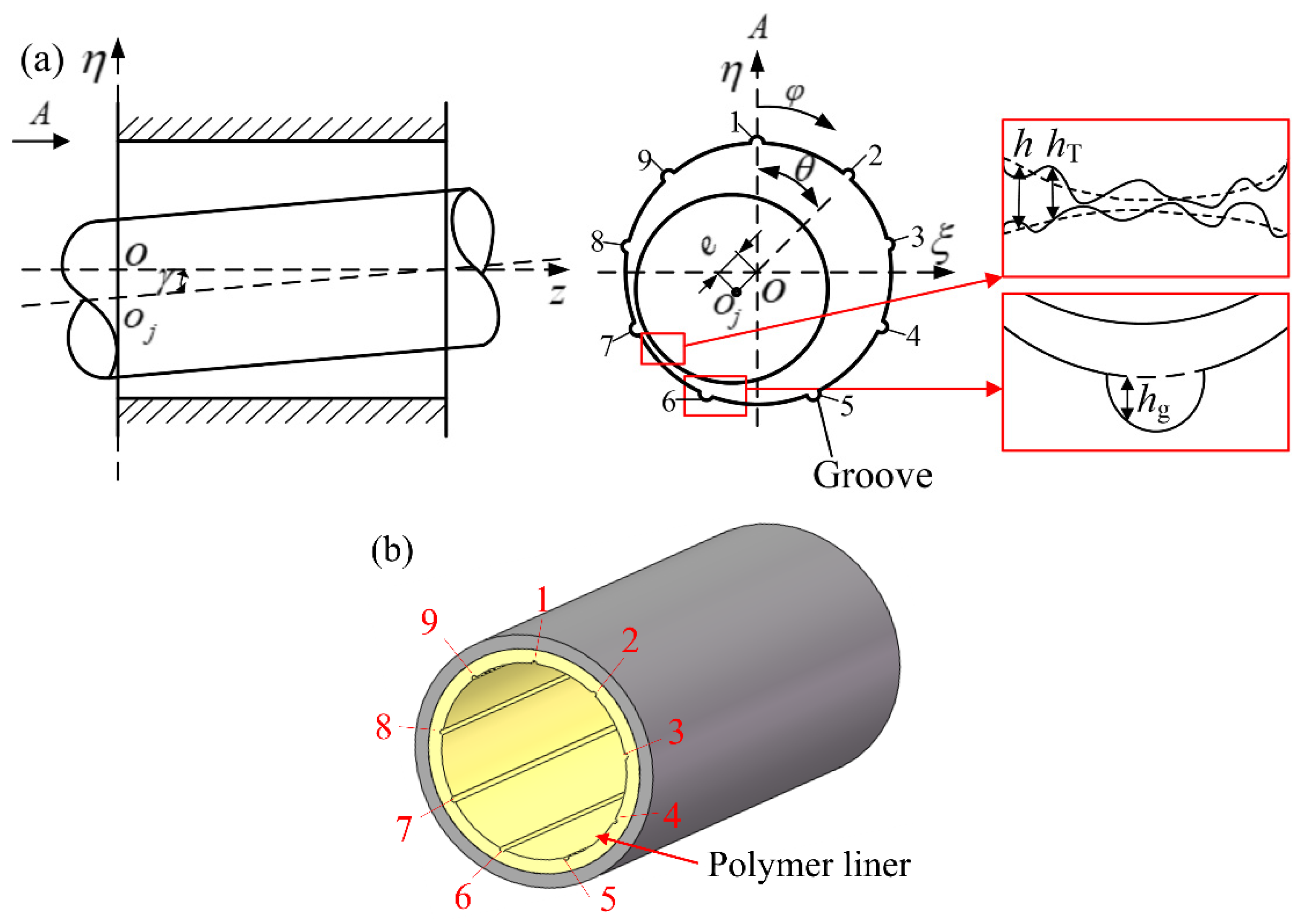
Figure 1. The misaligned water-lubricated polymer bearing with grooves: (a) schematic diagram; (b) a three-dimensional model. ε and θ is the eccentricity ratio and attitude angle of the journal at the axial section where the coordinate origin is located. γ is the misalignment angle. h is the nominal film thickness. hT is the local film thickness.
Lubricants 10 00336 g001
Figure 2. Flowchart of the numerical procedure.
Lubricants 10 00336 g002
Figure 3. Mean water film pressure at measuring points [31].
Lubricants 10 00336 g003
Figure 4. The film thickness distributions of the bearing versus length–diameter ratios: (a) misaligned bearing with L/D = 1; (b) misaligned bearing with L/D = 2; (c) aligned bearing with L/D =1; (d) aligned bearing with L/D = 2.
Lubricants 10 00336 g004
Figure 5. Film pressure distributions of the bearing versus length–diameter ratios: (a) misaligned bearing with L/D = 1; (b) misaligned bearing with L/D = 2; (c) aligned bearing with L/D = 1; (d) aligned bearing with L/D = 2.
Lubricants 10 00336 g005
Figure 6. The film thickness distributions of the bearing versus liner thicknesses: (a) misaligned bearing with a liner thickness of 10 mm; (b) misaligned bearing with a liner thickness of 30 mm; (c) aligned bearing with a liner thickness of 10 mm; (d) aligned bearing with a liner thickness of 30 mm.
Lubricants 10 00336 g006
Figure 7. Film pressure distributions of the bearing versus liner thicknesses: (a) misaligned bearing with a liner thickness of 10 mm; (b) misaligned bearing with a liner thickness of 30 mm; (c) aligned bearing with a liner thickness of 10 mm; (d) aligned bearing with a liner thickness of 30 mm.
Lubricants 10 00336 g007
Figure 8. Film thickness distributions of the bearing versus clearance ratios: (a) misaligned bearing with ψ = 0.17%; (b) misaligned bearing with ψ = 0.28%; (c) aligned bearing with ψ = 0.17%; (d) aligned bearing with ψ = 0.28%.
Lubricants 10 00336 g008
Figure 9. Pressure distributions of the bearing versus clearance ratios: (a) misaligned bearing with ψ = 0.17%; (b) misaligned bearing with ψ = 0.28%; (c) aligned bearing with ψ = 0.17%; (d) aligned bearing with ψ = 0.28%.
Lubricants 10 00336 g009
Figure 10. The film thickness distributions of the bearing versus journal speeds: (a) misaligned bearing with journal speed of 100 r/min; (b) misaligned bearing with journal speed of 200 r/min; (c) aligned bearing with journal speed of 100 r/min; (d) aligned bearing with journal speed of 200 r/min.
Lubricants 10 00336 g010
Figure 11. Pressure distributions of the bearing versus journal speeds: (a) misaligned bearing with journal speed of 100 r/min; (b) misaligned bearing with journal speed of 200 r/min; (c) aligned bearing with journal speed of 100 r/min; (d) aligned bearing with journal speed of 200 r/min.
Lubricants 10 00336 g011
Figure 12. Lubricating film thickness distributions of the bearing versus eccentricity ratios: (a) misaligned bearing with ε = 1.00; (b) misaligned bearing with ε = 1.01; (c) aligned bearing with ε = 1.00; (d) aligned bearing with ε = 1.01.
Lubricants 10 00336 g012
Figure 13. Film pressure distributions of the bearing versus eccentricity ratios: (a) misaligned bearing with ε = 1.00; (b) misaligned bearing with ε = 1.01; (c) aligned bearing with ε = 1.00; (d) aligned bearing with ε = 1.01.
Lubricants 10 00336 g013
Table 1. Bearing parameters used in [8].
Journal diameter (m)0.52
Bearing length (m)1.20
Clearance ratio0.23%
Journal speed (m/s)60
Lubricant viscosity (Pa·s)0.062
The roughness of the journal surface (μm)4.3
The roughness of bearing bush (μm)4.3
Externally applied load (kN)215
Table 2. The maximum mean hydrodynamic pressure versus misalignment angle.
Misalignment Angle (mrad)Results from [8] (MPa)Results Obtained by the Proposed Model (MPa)
0.3254.384.41
0.3334.704.73
0.3425.075.11
0.3505.485.52
0.3585.925.99
Table 3. Parameters of the bearing.
ParameterValueParameterValue
Journal diameter (mm)700Length–diameter ratio2
Clearance ratio0.22%Groove number9
Groove angle (°)4LubricantWater
Elastic modulus of the liner (Pa)4.4 × 10⁸Elastic modulus of the journal (Pa)2.11 × 10¹¹
Poisson’s ratio of the liner0.45Poisson’s ratio of the journal0.3
Liner surface roughness (μm)2.4Journal surface roughness (μm)0.8
Liner thickness (mm)20Contact friction coefficient0.2
Rated speed (rpm)200Eccentricity ratio1.01
Table 4. Bearing characteristics versus length–diameter ratios.
Attitude Angle (°)Load-Carrying Capacity (kN)Friction Force (N)Friction Coefficient
Bearing with L/D = 1 and γ = 0.025 mrad4.8688.7391.80.00442
Bearing with L/D = 2 and γ = 0.025 mrad4.64127.6449.90.00353
Aligned bearing with L/D = 13.86127.4513.30.00403
Aligned bearing with L/D = 23.87262.8760.20.00289
Table 5. Bearing characteristics versus liner thicknesses.
Attitude Angle (°)Load-Carrying Capacity (kN)Friction Force (N)Friction Coefficient
Bearing with liner thickness of 10 mm and γ = 0.025 mrad4.58165.3584.10.00353
Bearing with liner thickness of 20 mm and γ = 0.025 mrad4.64127.6449.90.00353
Bearing with liner thickness of 30 mm and γ = 0.025 mrad4.79107.9302.00.00280
Aligned bearing with liner thickness of 10 mm3.44362.61051.50.00290
Aligned bearing with liner thickness of 20 mm3.87262.8760.20.00289
Aligned bearing with liner thickness of 30 mm4.32204.2340.20.00167
Table 6. Bearing characteristics versus clearance ratios.
Attitude Angle (°)Load-Carrying Capacity (kN)Friction Force (N)Friction Coefficient
Bearing with ψ = 0.17% and γ = 0.025 mrad5.51132.8188.80.00142
Bearing with ψ = 0.22% and γ = 0.025 mrad4.64127.6449.90.00353
Bearing with ψ = 0.28% and γ = 0.025 mrad4.58124.8502.30.00402
Aligned bearing with ψ = 0.17%4.58266.2233.50.00087
Aligned bearing with ψ = 0.22%3.87262.8760.20.00289
Aligned bearing with ψ = 0.28%3.37253.5910.90.00359
Table 7. Bearing characteristics versus journal speeds.
Attitude Angle (°)Load-Carrying Capacity (kN)Friction Force (N)Friction Coefficient
Bearing with the rotational speed of 100 r/min and γ = 0.025 mrad4.5884.23416.50.00494
Bearing with the rotational speed of 200 r/min and γ = 0.025 mrad4.64127.6449.90.00353
Aligned bearing with the rotational speed of 100 r/min3.44202.2757.10.00375
Aligned bearing with the rotational speed of 200 r/min3.87262.8760.20.00289
Table 8. Bearing characteristics versus eccentricity ratios.
Attitude Angle (°)Load-Carrying Capacity (kN)Friction Force (N)Friction Coefficient
Bearing with ε = 1.00 and γ = 0.025 mrad5.9388.787.10.00098
Bearing with ε = 1.01 and γ = 0.025 mrad4.64127.6449.90.00353
Aligned bearing with ε = 1.003.57184.4116.70.00063
Aligned bearing with ε = 1.013.87262.8760.20.00289
Publisher’s Note: MDPI stays neutral with regard to jurisdictional claims in published maps and institutional affiliations.