Article

Microstructure and Performance of Fe50Mn30Cr10Ni10 High-Entropy Alloy Produced by High-Efficiency and Low-Cost Wire Arc Additive Manufacturing

1
College of Automotive and Mechanical Engineering, Changsha University of Science and Technology, Changsha 410114, China
2
National Institute of Defense Technology Innovation, Academy of Military Sciences PLA China, Beijing 100072, China
*
Authors to whom correspondence should be addressed.
Lubricants 2022, 10(12), 344; https://doi.org/10.3390/lubricants10120344
Submission received: 27 October 2022 / Revised: 20 November 2022 / Accepted: 29 November 2022 / Published: 2 December 2022
(This article belongs to the Special Issue Corrosion and Tribocorrosion Behavior of Metals and Alloys)

Abstract

:
High-entropy alloys exhibiting superior properties have great potential applications in various fields. The ability to achieve efficient and economical production of large size and complex structures of high-entropy alloy is of great significance to promoting its engineering application. Additive manufacturing is the key method to produce the complex component; however, the current trend in additive manufacturing of high-entropy alloys focuses on laser additive manufacturing, which is expensive and time-consuming. Herein, we developed a wire arc additive manufacturing (WAAM) method with high-efficiency and a low-cost Fe50Mn30Cr10Ni10 high-entropy alloy was successfully produced. The as-produced alloy was composed of face-centered cubic (FCC) phase with minor σ phase. Its microstructure mainly exhibited dendritic and cytosolic dendritic crystals. Mechanical strength of the additive manufactured alloy reached about 448 MPa with a high fracture elongation up to 80%. The additive manufactured alloy had good corrosion resistance with a protecting layer formed on the surface after corrosion testing, which was much better than 45 steel. Additionally, the frictional performance of the additive manufactured alloy was characterized against the grinding parts of steel and Al2O3 balls, and the corresponding friction mechanism was discussed.

1. Introduction

Conventional alloys are usually dominated by one or two elements, and the microstructure and properties of the alloy are improved by adding small amounts of elements. In 2004, Ye et al. broke the traditional alloy design principle and proposed the concept of the “high-entropy alloy” (HEAs) for the first time [1]. HEAs are multi-principal alloys composed of five or more primary elements in equimolar or near-molar ratios. Due to their unique high-entropy effect, HEAs have simple solid solution structures and excellent comprehensive properties, such as high hardness, high strength, high thermal stability, superior corrosion resistance and good wear resistance [2,3,4]. Therefore, HEAs have great engineering application in aerospace and marine equipment fields. Generally, the preparation methods of high-entropy alloys are mostly based on the traditional arc melting technology. However, the limitations of the melting cavity, which makes it difficult to prepare complex shape structural parts, lead to the limitation of high-entropy alloys in practical industrial applications.
Additive manufacturing (AM) provides a good option for the production of complex structural parts, and the main method currently used for AM of HEAs is laser additive manufacturing (LMD) [5,6]. Gao et al. [7] used LMD to prepare the CoCrFeMnNi high-entropy alloy and they investigated the evolution of the alloy structure under rapid solidification conditions during the forming process. The results show that the structure of the molten pool changes from equiaxed crystals to dendrites during the forming process, and that the formed parts exhibit high strength and toughness. Ocelik et al. [8] investigated the effect of the laser remelting process on the structure and mechanical properties of formed parts during the preparation of AlCoCrFeNi HEA by LMD. The results showed that the laser cooling rate was a key factor in determining the phase composition and elemental distribution of the AlCoCrFeNi HEA. Qiu et al. [9] investigated the low-temperature tensile properties of LMD-prepared CrMnFeCoNi HEAs and showed that the alloys consisted of homogeneous FCC phases with uniform composition distribution. The LMD-formed alloys had a large dislocation density, which gave them excellent room-temperature and low-temperature tensile properties, especially high yield strength. Tan et al. [10] summarized the cause of the anisotropic and heterogeneous microstructures and the mechanical properties of metal AM parts as their microstructural features or defects. Mirsayar [11] investigated the effect of material anisotropy on the fatigue crack growth behavior in additively manufactured materials by developing an energy-based criterion. It is found that both the material anisotropies resulting from build orientation and the T-stress play remarkable roles in the fatigue crack growth behavior of 3D-printed components. Popovich et al. [12] examined functionally graded Inconel 718 produced with local functionalities via crystallographic texture, grain size and anisotropy optimization. However, LMD has some drawbacks, such as low efficiency and high cost. Therefore, in order to expand applications of HEAs, it was important to develop a high-efficiency and low-cost AM method. In the present work, we prepared Fe50Mn30Co10Cr10 (HEA) wire material and used WAAM to try to prepare AM HEA components. The microstructure and properties were investigated.

2. Experimental Procedures

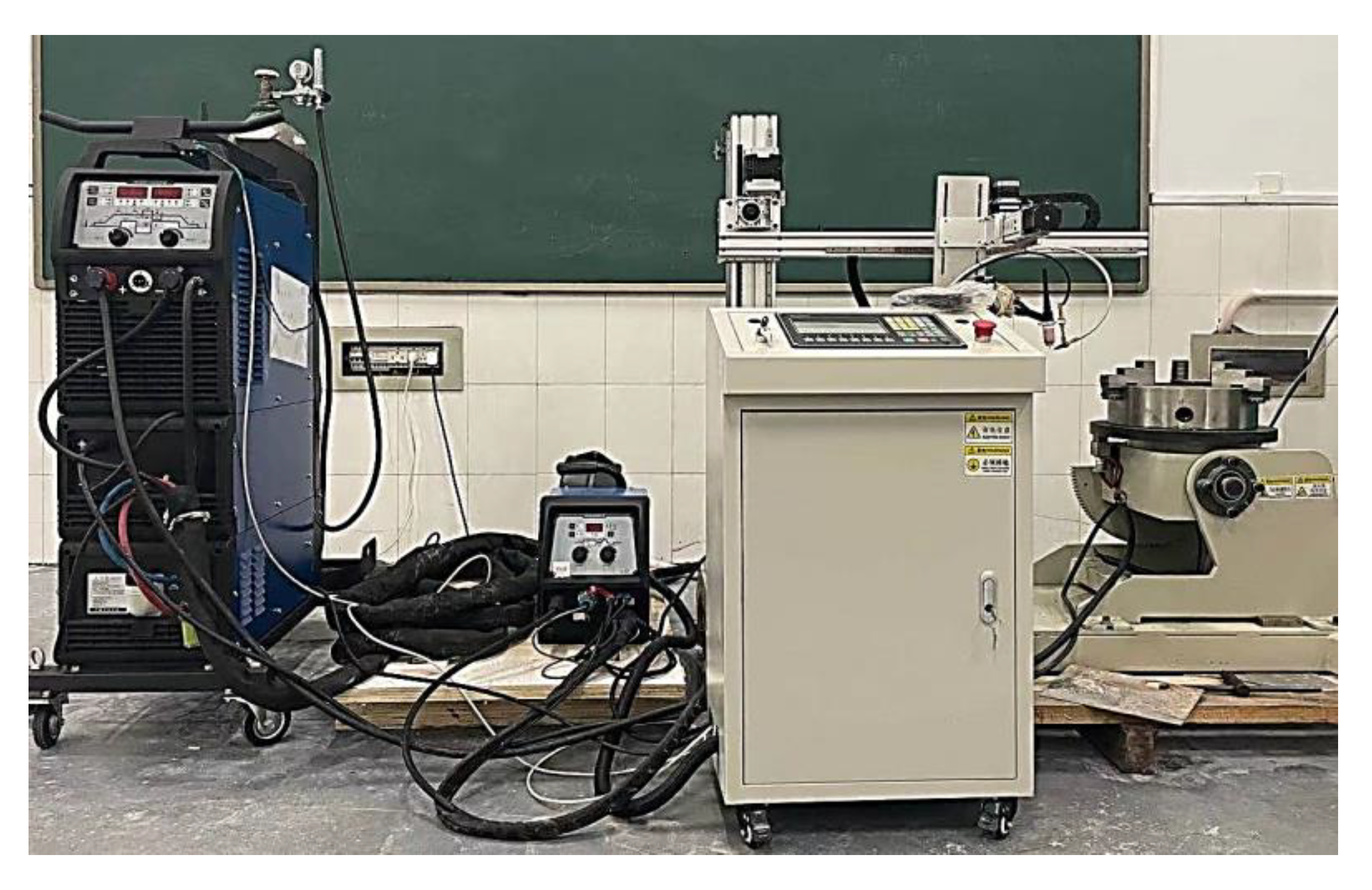
2.1. Welding Wire and Additive Manufactured High-Entropy Alloy Preparation

Before preparing the wire, the desired powder was prepared according to design requirements then poured into a mixer, thoroughly stirred and successively filtered through 80–100 mesh sieves to eliminate larger particles. The 301 stainless steel strips were formed using this method, and the equipment used was made by Jiangsu Nantong Machinery and Electrical Equipment Company. The diameter of the wire gradually changed to 1.6 mm after repeated pulling. We then cleaned and removed any powder left on the surface of the wire during the pulling process. Finally, the prepared wire was stored in a dry environment, ready for use when welding.
As a substrate, 304 SS with a size of 200 mm × 100 mm × 10 mm was used. The Fe50Mn30Cr10Ni10 (HEA) welding wire with Φ1.6 mm was used as AM material. The chemical compositions of HEA welding wire are Fe 50%, Mn 30%, Cr 10% and Ni 10% (at.%). We used silicon carbide abrasive paper with grit number 400 to ground the substrate and cleaned it with a mixing solvent of 15% acetone and 85% alcohol before additive manufacturing. A WSM-400R inverter pulse argon arc welding machine (CHU cutting, Shanghai, China) equipped with EWM THTRIX drive 4L wire feeder was employed to prepare the sample, as seen in Figure 1. The optimized AM process parameters were set according to Table 1.

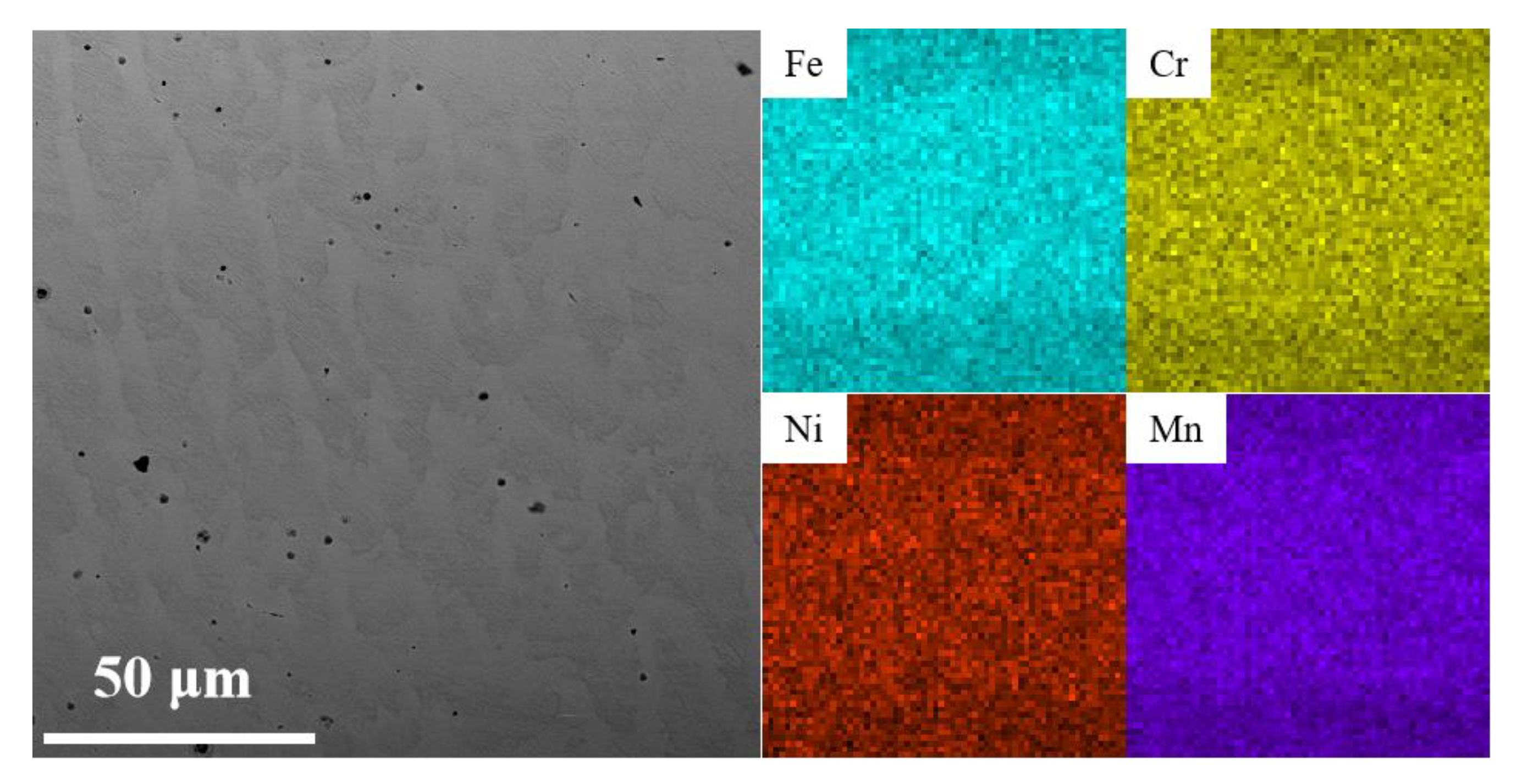
2.2. Microstructure and Composition Characterization

The additive manufactured high-entropy alloy (AM HEA) was cut to the required size for microstructure characterization. The AM HEA was ground by silicon carbide abrasive paper, polished with an abrasive paste and then etched using FeCl3 (10 g) + HCl (45 mL) + H2O (60 mL). Then, its microstructure and elemental distribution were analyzed with a Prox desktop electron microscope (SEM) equipped with an energy dispersive spectrometer (EDS). The alloy microstructures in different states were observed using an IE500M optical microscope (Shunyu Instrument Company Limited, Ningbo, China). The phase composition of samples was identified by X-ray diffraction (XRD, Bruker-D8 Advance system with Cu Kα radiation) with a scanning rate of 5°/min and a scanning range of 30–80°.

2.3. Performance Testing

The tensile test with gauge dimensions of 13 mm × 2.5 mm × 1.5 mm was carried out at room temperature with a strain rate of 5 × 10⁻⁴ s−1 using a universal tensile testing machine (SUST CMT5105GL, Sanshi Taijie Electrical Equipment Company Limited, Zhuhai, China). To ensure the accuracy of the tensile tests, at least three samples were tested in the same condition. We then observed the microstructure of the fracture.
The electrochemical corrosion behavior of the AM HEA was performed at room temperature in 3.5 wt.% NaCl solution. Corrosion solutions were prepared with analytical reagents and deionized water. Electrochemical corrosion measurements were carried out using an electrochemical workstation (Solartron 1470E Jomei Automation Equipment Company, Wuhan, China) with a three-electrode cell. The specimens were sealed with epoxy resin and connected with Cu wires as the working electrodes, the saturated calomel electrode and the platinum plate electrode, were used as the reference electrode and the auxiliary electrode, respectively. Before the electrochemical tests, the constant potential polarization with a potential of −0.8 V for 10 min was carried out to remove the air-formed oxide film of the working electrodes, the open circuit potential (OCP) was tested for 0.5 h and the final stable potential was recorded. Then, electrochemical impedance spectroscopy (EIS) measurements were performed with a test frequency between 0.01 Hz and 1 × 10⁶ Hz. The scanning range of potentiodynamic polarization was −0.25~1.5 V, and the scanning speed was 1 mV/s.
The wear performance of AM HEA was tested by a reciprocating friction and wear tester (MDW-05) using a carbon steel ball and Al2O3 ball of Φ 6.5 mm in loading force of 100 N for 30 min with running frequency of 2 Hz. After a certain period of testing under the preset test load, the mass loss of the frictional wear was measured by weighing the before and after masses using an electronic balance with an accuracy of 0.1 mg, thus reflecting the wear resistance of the material. After each group of wear specimens is tested, the difference between the before and after masses of the specimens is weighed, which is the mass loss of wear. After the test, the worn surface of the AM HEA was observed by SEM to analyze.

3. Experimental Results and Discussion

3.1. Phase Composition and Microstructure of the AM HEA

Figure 2 presents the XRD pattern of AM HEA. The FCC phase and σ phase were detected. The σ phase was formed by using this method, which was different from the alloy prepared by other methods [13].
The microstructure of the specimen was analyzed. The cross-sectional morphology is shown in Figure 3, where fusion lines can be seen between the layers. Figure 4 shows the microstructures of AM HEA. The microstructure of the AM HEA is dendritic, with dendritic tissue in the bright white area and inter-dendritic structures in the dark gray area. Figure 4a–c shows the microstructure from the bottom to the top of the additive manufacturing. It can be seen that the grain size gradually decreases from the bottom to the top, which may be related to the heat dissipation of the surface. According to the report in Ref. [14], the shape of the crystal grain is highly related to the degree of subcooling ΔT, the solidification rate R, the temperature gradient Tg and the diffusion coefficient DL during the solidification. According to the different relationship of Tg, R, ΔT and DL, in (1) Tg/R > ΔT/DL, the crystal is a columnar structure, and in (2) Tg/R < ΔT/DL, the crystal is a plane equiaxed structure. The center temperature of the molten pool is high, the temperature gradient Tg is the largest, the temperature at the edge position is low and the edge position speed is much greater than the center of the molten pool during heat dissipation; thus, the edge solidification rate R and the degree of subcooling ΔT are relatively large. Therefore, from the center to the edge of the molten pool, Tg/R gradually decreases, ΔT/DL gradually increases and the crystal grains gradually transform from dendritic to equiaxed.
To further analyze the element distribution of the AM HEA, the EDS mappings were performed, and the results are shown in Figure 5 and Table 2. It can be seen that the microstructure of the AM HEA is dendritic, consisting of dendrites and inter-dendrites. The elements are uniformly distributed in the AM HEA, and the elemental percentage is also basically distributed according to the welding wire.

3.2. Mechanical Properties

The mechanical properties were tested at room temperature and their engineering tensile stress-strain curves were presented in Figure 6a. As seen, the ultimate tensile strength (UTS) of the AM HEA was about 448 MPa. Surprisingly, the fracture strain (FS) was close to 80%, which shows very excellent plasticity. In order to further reveal the work hardening responses of the material, the strain-hardening rate was plotted in Figure 6b. Obviously, the AM HEA shows a monotonic two-stage decrease, and the two-stage hardening response was universally discerned in alloys closely related to dislocations configurations. At the initial strain hardening stage, the rapid decline implies a typical dislocation-hardening nature depicted by the classical Taylor model [15,16,17]. In Figure 6c, it is clear that the mechanical properties of this work are better than HEA preparation by electric arc melting and aluminum alloy, which indicates that the additive manufacturing technology proposed in this work has an important engineering application value [13,18].
Figure 7 shows the fracture morphology of AM HEA after tensile testing. A large number of dimples were observed in AM HEA, which indicated that AM HEA displayed a typical plastic fracture. Therefore, it exhibits a greater tensile strain during the tensile process. The generation of these dimples were mainly due to the stress concentration generated by defects such as pores and inclusions present inside the specimen during the tensile process. When the loading reaches the yield limit of the material, the material begins to deform plastically, forming a crack source at the defect and expanding to form a tough nest-like fracture morphology.

3.3. Electrochemical Corrosion Performance

Polarization and Electrochemical Impedance Spectroscopy Results

Figure 8a shows the potentiodynamic polarization curves of AM HEA and 45 steel in 3.5 wt.% NaCl aqueous solution. Obvious passivation behavior was observed in AM HEA, while the obvious inflection points of passivation behaviors were not found in the polarization curve of 45 steel. Table 3 shows the polarization parameters of AM HEA and 45 steel polarization curves obtained by the Tafel extrapolation method. As can be seen from the table, the corrosion current density of the 45 steel and AM HEA are 1.07 × 10⁻⁵ A/cm2 and 4.81 × 10⁻⁶ A/cm2, respectively. Based on the above analysis, corrosion resistance of HEA AML is better than the 45 steel in 3.5 wt.% NaCl aqueous solution.
During the electrochemical reaction, the higher the impedance of the passivation film, the better its protection. The EIS was used to quantify the magnitude of the impedance of the passivation film. Based on the results of the EIS, the corrosion mechanism of these alloys was explained. Figure 8b shows the equivalent circuit (EC) used to fit the EIS data. The first part of the EC consists of the solution resistance (Rs), the charge transfer resistance (Rpass) and the passivated film capacitance (Cpass), where the capacitance is replaced by a common phase angle element (CEPpass) to compensate for the effects due to system inhomogeneities [19,20,21].
In Figure 8c, all Nyquist curves for the passivation condition are characterized by unfinished semi-circular arcs, which are related to the charge transfer process occurring at the interface. The characteristics of the semi-circles depend on the electrical potential. Usually, the larger radius of the arc represents the greater charge transfer resistance of the material. It is clearly observed in the inquest diagram that the AM HEA has higher arc radius than the 45 steel, so the AM HEA has better corrosion resistance.
From the Bode plots of AM HEA and 45 steel (Figure 8d), it can be seen that the frequency shows a certain linear relationship with log |Z|. Generally, the value of |Z| with a fixed frequency of 0.1 Hz in the low frequency area corresponds to the polarization resistance of the alloy, which can reflect the corrosion resistance of the alloy to some extent. The |Z| in the medium frequency area (100~102 Hz) is linearly related to f, the slope is close to −1 and the phase angle reaches a maximum, which is characteristic of the capacitance response. The number of phase angle peaks determines its capacitance number while for the high frequency area (>103 Hz), the value of the phase angle approaches 0, indicating that its impedance is mainly determined by the electrolyte resistance [22,23].
Table 4 shows the detailed fitting EIS parameters of AM HEA and 45 steel. The decrease of Y0 of CPEpass indicated a decrease in the porosity and a more compact and protective passivation film [24]. Rpass is the resistance of the passive film, and its value illustrates the capability of the passivation film to impede charge transfer from the metal. According to the simulation data in Table 4, the capacitance of the passivation film of the corresponding sample can be calculated. The capacitance values of AM HEA and 45 steel are 6.78 × 10⁻⁵ F and 7.69 × 10⁻⁴ F, respectively.
In the Young model [20], the passivated film capacitance is inversely proportional to its thickness, which also explains why AM HEA has bigger effective passivated film thickness (~1.01 nm). The film thickness of 45 steel is about 0.90 nm, and the close thickness corresponds to the close of the stable open circuit voltage. Thicker passivation films imply greater resistance to charge transfer, which is consistent with the results of the Rpass.
The micro-morphology of AM HEA and 45 steel in different states after potentiodynamic polarization in 3.5 wt.% NaCl solution was captured. As seen in Figure 9a1,b1, the pitting pits and corrosion products appeared on the surface of AM HEA and 45 steel to different degrees. It can be seen from Figure 9a1,a2 that the entire surface of the 45 steel was corroded, and many corrosion products appear on the surface. However, the corrosion area of AM HEA was smaller, and the corrosion form was pitting corrosion. Figure 9b2 shows a uniform and dense microstructure in the pitting pits. This indicated that a passivation film was formed during the corrosion process, preventing further corrosion of the alloy. This did not occur in 45 steel, further indicating that the corrosion resistance of AM HEA is better than 45 steel.

3.4. Wear Performance

The wear behavior was analyzed for AM HEA. The relationship of friction coefficient versus wear time was plotted in Figure 10a. As seen, the coefficient of friction (COF) curves of the AM HEA rose rapidly at the beginning of the frictional wear, and then gradually became stable with the implementation of frictional wear. Finally, both curves fluctuate at 0.35. Figure 10b shows the wear track dimensions of the wear marks of AM HEA; it can be seen that the wear marks of the steel ball were lighter and wider with the depth of 0.354 ± 0.01 mm and the width of 3.762 ± 0.01 mm, while those of the Al2O3 ball were deeper and narrower with the depth of 0.506 ± 0.01 mm and the width of 3.074 ± 0.01 mm.
To further understand the wear mechanisms of the AM HEA, SEM analysis was conducted. The worn surface morphologies and the corresponding EDS mappings were shown in Figure 9. As seen in Figure 11a, there were a large number of three-body abrasive grains of different sizes and various shapes on the surface of the wear surface. Under high wear speed, a large amount of frictional heat accumulation led to the softening of the AM HEA, and these three-body abrasive grains caused serious damage to the surface of the wear surface. At the same time, due to the existence of severe adhesive wear, the tearing becomes more severe as the sliding speed increases and the plastic deformation zone expands. This leads to the formation of deep tearing pits with large dimensions, causing mechanical damage. At this time, the forms of wear are severe adhesive wear and abrasive wear. It can be seen from the element distribution mappings of the abrasion marks’ surface that the distribution of Fe and O elements were relatively consistent, which indicated that, during the friction process, the material on the steel ball surface was oxidized and transferred to the abrasion marks’ surface in large quantities, forming a discontinuous layer of Fe2O3 friction film. The presence of Fe2O3 played a lubricating role and prevented further wear between the friction ball and the wear scar surface, thus improving the wear resistance of the AM HEA. In Figure 11b, many furrows and tiny particles appeared on the worn surface. This was mainly formed when the AM HEA and the hard ceramic sphere’s Al2O3 ball were crushed into fragments of each internal phase under continuous pressure. The EDS results showed that the oxygen content of the debris (position 1) was obviously higher than those of other areas, indicating that the peeled materials were oxide layers. This friction film was a relatively intact friction film formation on the surface of the wear marks after the composite material test, which can impede the wear of the friction surface [25].

4. Conclusions

In this work, the TIG arc AM was developed, and the AM HEA was prepared on the surface of 304 SS. The microstructure evolution, mechanical properties and corrosion resistance were systematically researched. The main results are summarized as follows:
(1)
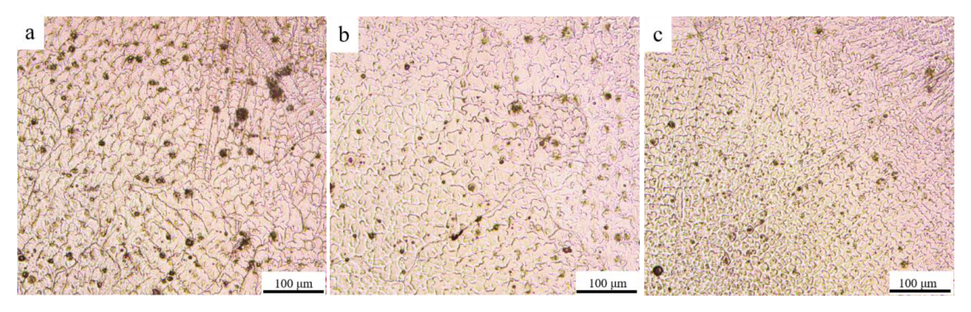
The FCC phase and σ phase were detected in the AM HEA and the microstructure of the AM HEA is dendritic, consisting of dendrites and inter-dendrites. The grain size decreases from the bottom to the top;
(2)
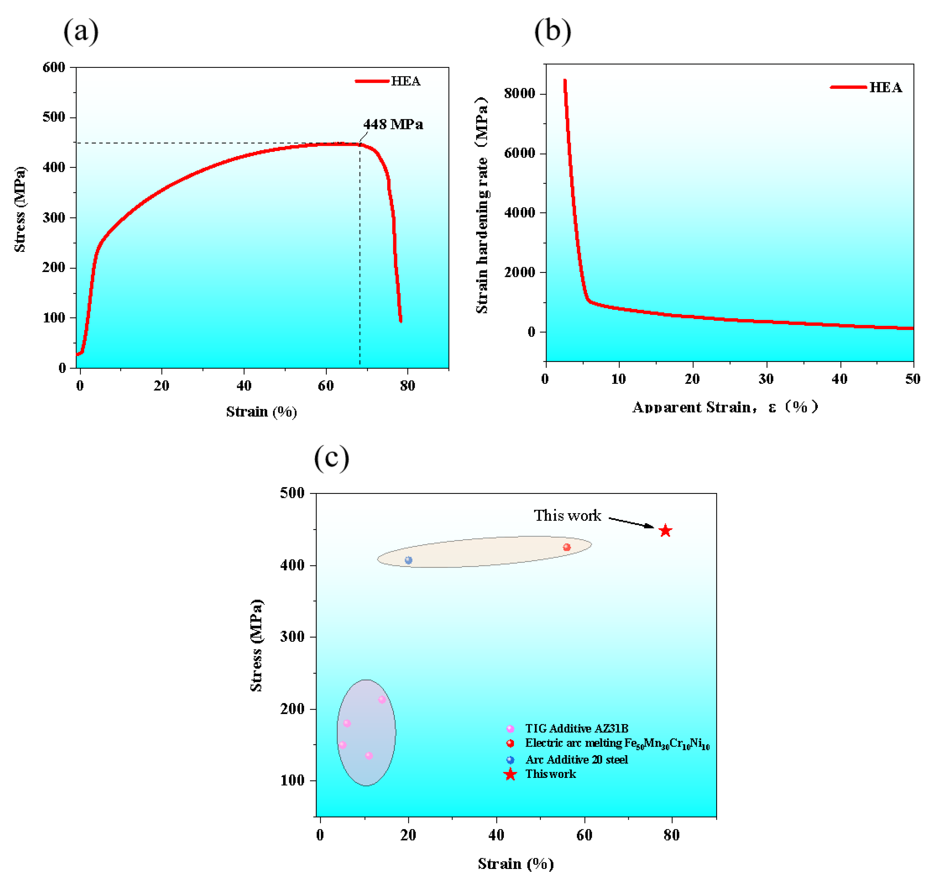
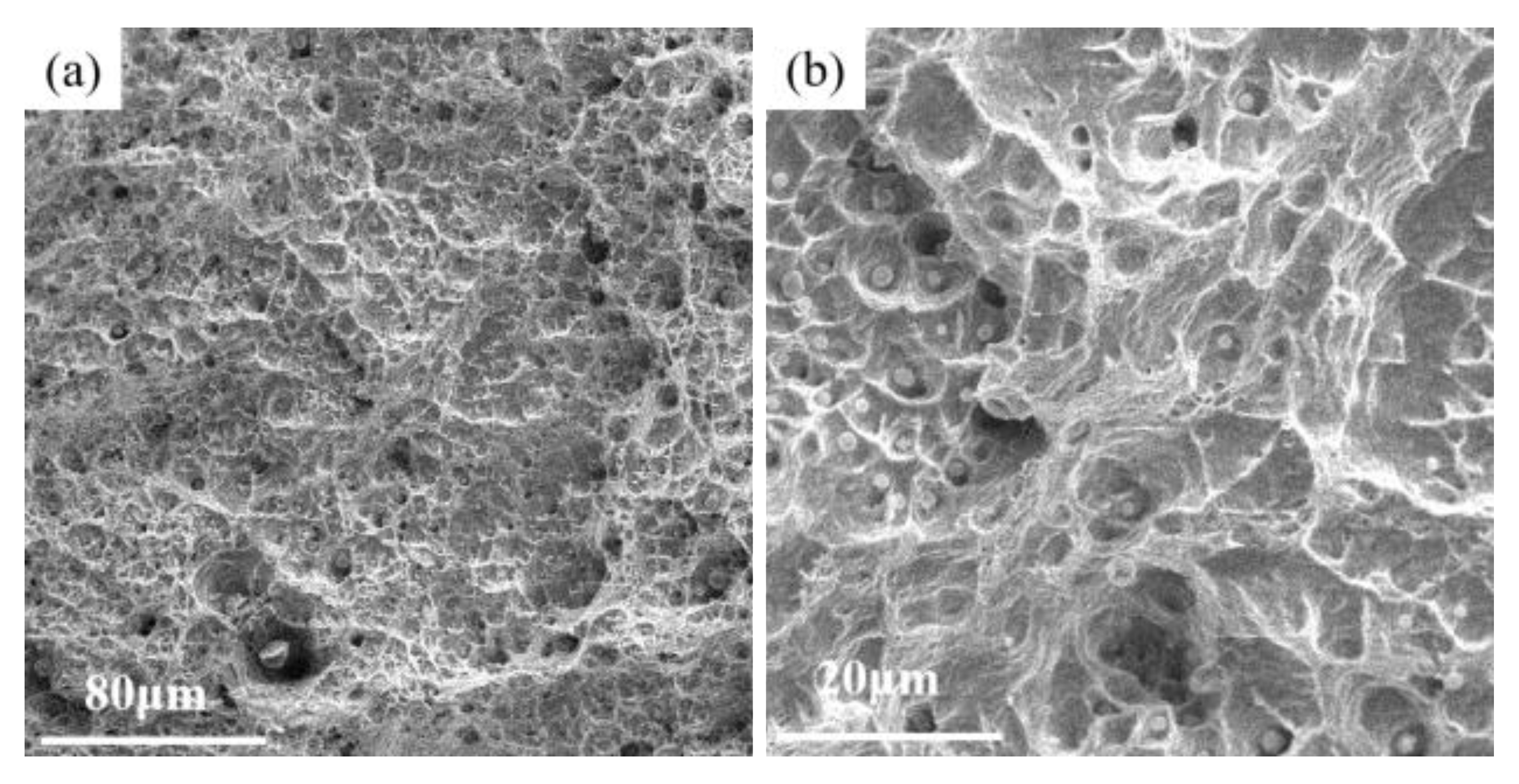
The AM HEA was tested for tensile mechanical properties at room temperature, and its ultimate strength was about 448 MPa with a high plasticity up to 80%;
(3)
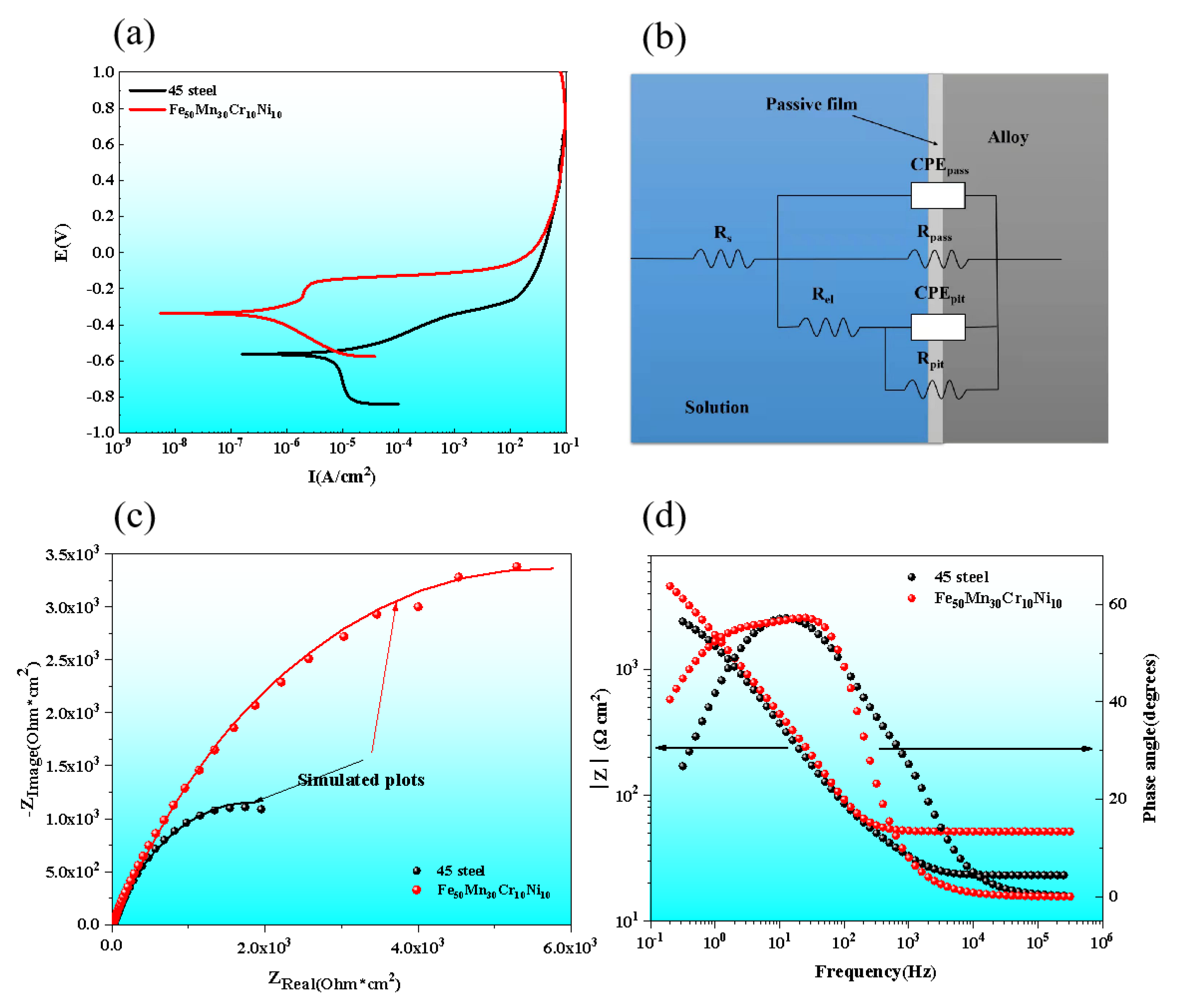
The corrosion current density of AM HEA was lower, and the corrosion potential was higher. The corrosion current density of AM HEA was 4.81 × 10⁻⁶ A/cm2 compared with 1.07 × 10⁻⁵ A/cm2 of 45 steel which was much lower. The corrosion potential of AM HEA was −0.3808 V, which was higher than the corrosion potential of 45 steel (−0.5629 V). Compared with 45 steel, the corrosion rate and corrosion tendency of AM HEA was smaller, showing better corrosion resistance;
(4)
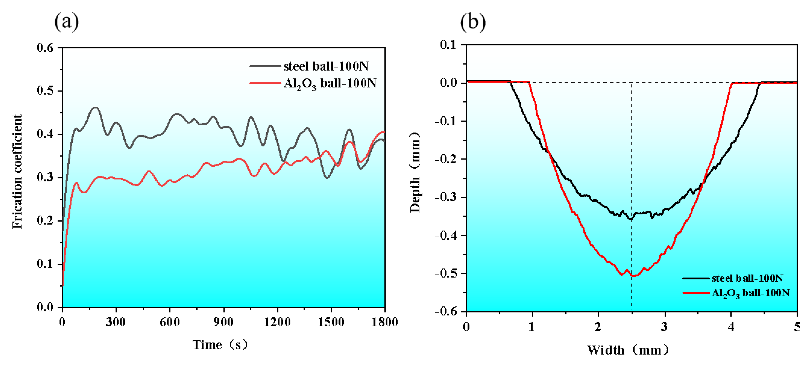
Two coefficient of friction (COF) curves of the AM HEA were fluctuated at 0.35. The wear marks of the steel ball were lighter and wider with the depth of 0.354 ± 0.01 mm and the width of 3.762 ± 0.01 mm, while those of the Al2O3 ball were deeper and narrower with the depth of 0.506 ± 0.01 mm and the width of 3.074 ± 0.01 mm.

Author Contributions

X.Z. and Y.T. contributed the central idea, analyzed most of the data, and wrote the initial draft of the paper. The remaining authors contributed to refining the ideas, carrying out additional analyses and finalizing this paper. All authors have read and agreed to the published version of the manuscript.

Funding

This work was supported by National Natural Science Foundation of China (No. 92166105 and 52005053), High-Tech Industry Science and Technology Innovation Leading Program of Hunan Province (No.2020GK2085), the Science and Technology Innovation Program of Hunan Province (No. 2021RC3096) and Changsha Key R&D Program Project (No. kh2201275).

Data Availability Statement

Not applicable.

Conflicts of Interest

The authors declare that they have no financial interests or personal relationships that could have influenced the work reported in this paper.

References

  1. Yeh, J.-W.; Chen, S.K.; Lin, S.-J.; Gan, J.-Y.; Chin, T.-S.; Shun, T.-T.; Tsau, C.-H.; Chang, S.-Y. Nanostructured High-Entropy Alloys with Multiple Principal Elements: Novel Alloy Design Concepts and Outcomes. Adv. Eng. Mater. 2004, 6, 299–303. [Google Scholar] [CrossRef]
  2. Gwalani, B.; Gorsse, S.; Choudhuri, D.; Zheng, Y.; Mishra, R.S.; Banerjee, R. Tensile yield strength of a single bulk Al0. 3CoCrFeNi high entropy alloy can be tuned from 160 MPa to 1800 MPa. Scr. Mater. 2019, 162, 18–23. [Google Scholar] [CrossRef]
  3. Tong, Y.; Zhang, H.; Huang, H.; Yang, L.; Hu, Y.; Liang, X.; Hua, M.; Zhang, J. Strengthening mechanism of CoCrNiMox high entropy alloys by high-throughput nanoindentation mapping technique. Intermetallics 2021, 135, 107209. [Google Scholar] [CrossRef]
  4. Zhang, H.; Tong, Y.; Cao, S.; Hu, Y.; Ji, X.; Tang, Q.; Yang, L.; Zhang, X.; Hua, M. Outstanding yield strength of CoCrNiTa0. 1 medium entropy alloy under the synergistic regulated with nanoprecipitation and grain refining. J. Alloys Compd. 2022, 919, 165715. [Google Scholar] [CrossRef]
  5. Debroy, T.; Wei, H.L.; Zuback, J.; Mukherjee, T.; Zhang, W. Additive manufacturing of metallic components—Process, structure and properties. Prog. Mater. Sci. 2018, 92, 112–224. [Google Scholar] [CrossRef]
  6. Ding, J.; Colegrove, P.; Mehnen, J.; Ganguly, S.; Almeida, P.S.; Wang, F.; Williams, S. Thermo-mechanical analysis of Wire and Arc Additive Layer Manufacturing process on large multi-layer parts. Comput. Mater. Sci. 2011, 50, 3315–3322. [Google Scholar] [CrossRef] [Green Version]
  7. Gao, X.; Lu, Y. Laser 3D printing of CoCrFeMnNi high-entropy alloy. Mater. Lett. 2019, 236, 77–80. [Google Scholar] [CrossRef]
  8. Ocelík, V.; Janssen, N.; Smith, S.N.; De Hosson, J.T.M. Additive manufacturing of high-entropy alloys by laser processing. Jom 2016, 68, 1810–1818. [Google Scholar] [CrossRef] [Green Version]
  9. Qiu, Z.; Yao, C.; Feng, K.; Li, Z.; Chu, P.K. Cryogenic deformation mechanism of CrMnFeCoNi high-entropy alloy fabricated by laser additive manufacturing process. Int. J. Lightweight Mater. Manuf. 2018, 1, 33–39. [Google Scholar] [CrossRef]
  10. Kok, Y.; Tan, X.; Wang, P.; Nai, M.; Loh, N.; Liu, E.; Tor, S. Anisotropy and heterogeneity of microstructure and mechanical properties in metal additive manufacturing: A critical review. Mater. Des. 2018, 139, 565–586. [Google Scholar] [CrossRef]
  11. Mirsayar, M. A generalized criterion for fatigue crack growth in additively manufactured materials–Build orientation and geometry effects. Int. J. Fatigue 2021, 145, 106099. [Google Scholar] [CrossRef]
  12. Popovich, V.A.; Borisov, E.V.; Popovich, A.A.; Sufiiarov, V.S.; Masaylo, D.V.; Alzina, L. Functionally graded Inconel 718 processed by additive manufacturing: Crystallographic texture, anisotropy of microstructure and mechanical properties. Mater. Des. 2017, 114, 441–449. [Google Scholar] [CrossRef]
  13. Bai, L.; Wang, Y.Z.; Yang, X.G.; Wang, R.B. Effect of Cr elements on the microstructure and properties of FeMnNiCr high-entropy alloy. Therm. Process. Process 2020, 49, 5. [Google Scholar] [CrossRef]
  14. Qiulin, W.; Yong, L.; Jinbo, Z.; Mingfu, L.; Zhengxing, M. Extreme High Speed Laser Cladding 316L Coating. J. Phys. Conf. Ser. 2021, 1965, 012083. [Google Scholar] [CrossRef]
  15. Kuhlmann-Wilsdorf, D. Strengthening Through LEDS. Strength Met. Alloys 1989, 1, 221–226. [Google Scholar] [CrossRef]
  16. Liu, X.; Jiang, S.; Lu, J.; Wei, J.; Wei, D.; He, F. The dual effect of grain size on the strain hardening behaviors of Ni-Co-Cr-Fe high entropy alloys. J. Mater. Sci. Technol. 2022, 131, 177–184. [Google Scholar] [CrossRef]
  17. Zhang, D.; Wang, H.; Zhang, J.; Xue, H.; Liu, G.; Sun, J. Achieving excellent strength-ductility synergy in twinned NiCoCr medium-entropy alloy via Al/Ta co-doping. J. Mater. Sci. Technol. 2021, 87, 184–195. [Google Scholar] [CrossRef]
  18. Chen, Y.-M.; Orazem, M.E. Impedance analysis of ASTM A416 tendon steel corrosion in alkaline simulated pore solutions—ScienceDirect. Corros. Sci. 2016, 104, 26–35. [Google Scholar] [CrossRef]
  19. Hirschorn, B.; Orazem, M.E.; Tribollet, B.; Vivier, V.; Frateur, I.; Musiani, M. Determination of effective capacitance and film thickness from constant-phase-element parameters. Electrochim. Acta 2010, 55, 6218–6227. [Google Scholar] [CrossRef]
  20. Kissi, M.; Bouklah, M.; Hammouti, B.; Benkaddour, M. Establishment of equivalent circuits from electrochemical impedance spectroscopy study of corrosion inhibition of steel by pyrazine in sulphuric acidic solution. Appl. Surf. Sci. 2006, 252, 4190–4197. [Google Scholar] [CrossRef]
  21. Sun, J.; Zhang, G.; Liu, W.; Lu, M. The formation mechanism of corrosion scale and electrochemical characteristic of low alloy steel in carbon dioxide-saturated solution. Corros. Sci. 2012, 57, 131–138. [Google Scholar] [CrossRef]
  22. Della Rovere, C.; Alano, J.; Silva, R.; Nascente, P.; Otubo, J.; Kuri, S. Characterization of passive films on shape memory stainless steels. Corros. Sci. 2012, 57, 154–161. [Google Scholar] [CrossRef]
  23. Luo, H.; Li, Z.; Mingers, A.M.; Raabe, D. Corrosion behavior of an equiatomic CoCrFeMnNi high-entropy alloy compared with 304 stainless steel in sulfuric acid solution. Corros. Sci. 2018, 134, 131–139. [Google Scholar] [CrossRef]
  24. Wei, L.; Liu, Y.; Li, Q.; Cheng, Y.F. Effect of roughness on general corrosion and pitting of (FeCoCrNi)0.89(WC)0.11 high-entropy alloy composite in 3.5 wt.% NaCl solution. Corros. Sci. 2018, 146, 44–57. [Google Scholar] [CrossRef]
  25. Huang, Y.; Hu, Y.; Zhang, M.; Mao, C.; Tong, Y.; Zhang, J.; Li, K.; Wang, K. On the enhanced wear resistance of laser-clad CoCrCuFeNiTix high-entropy alloy coatings at elevated temperature. Tribol. Int. 2022, 174, 107767. [Google Scholar] [CrossRef]
Figure 1. Arc Additive Manufacturing System.
Lubricants 10 00344 g001
Figure 2. XRD patterns of AM HEA.
Lubricants 10 00344 g002
Figure 3. Cross-section schematic diagram of additive manufacturing.
Lubricants 10 00344 g003
Figure 4. Microstructure of different position of AM HEA. (a) bottom, (b) middle, (c) top.
Lubricants 10 00344 g004
Figure 5. Micro-morphology and corresponding EDS mappings of AM HEA.
Lubricants 10 00344 g005
Figure 6. (a) The engineering tensile stress-strain curves at room temperature of AM HEA; (b) their strain-hardening rate curves; (c) the comparison of the fracture elongation-yield strength.
Lubricants 10 00344 g006
Figure 7. The fracture morphology of AM HEA. (a) Low magnification, (b) High magnification.
Lubricants 10 00344 g007
Figure 8. Polarization curves and EIS curves of HEA AML and 45 steel tested in 3.5 wt.% NaCl solution. (a) Polarization curves; (b) Nyquist plots; (c) bode plots; (d) equivalent circuit of EIS.
Lubricants 10 00344 g008
Figure 9. Micro-morphology of 45 steel and AM HEA in different states after potentiodynamic polarization in 3.5 wt.% NaCl solution. (a1) Micro-morphology of 45 steel after corrosion, (a2) Partial enlargement of a1, (b1) Micro-morphology of AM HEA after corrosion, (b2) Partial enlargement of b1.
Lubricants 10 00344 g009
Figure 10. (a) Friction coefficient curves; (b) wear track dimensions.
Lubricants 10 00344 g010
Figure 11. Worn surface morphologies and corresponding EDS mappings of AM HEA. (a) Steel ball-100N; (b) Al2O3 ball-100N.
Lubricants 10 00344 g011
Table 1. Process parameters of AM.
AM Current140 A
Wire feeding rate0.4 r/min
Welding torch speed100 mm/min
Swing distanceX5.5 mm, Y5 mm
Overlap distance4 mm
Arcing time1 s
Interrupting time1 s
Table 2. The EDS analyses of AM HEA.
AlloyElement Content (at.%)
FeMnCrNi
Nominal50301010
Overall53.0225.6211.3110.05
155.3126.1510.268.28
251.5225.3310.3512.80
352.2624.3811.3212.04
Table 3. Polarization parameters obtained from dynamic potential polarization tests of AM HEA and 45 steel.
SamplesElectrochemical Parameters
Ecorr (VSCE)Icorr (A/cm2)
45 steel−0.56291.07 × 10−5
HEA−0.38084.81 × 10−6
Table 4. Equivalent circuit parameter values of simulated EIS of AM HEA and 45 steel in 3.5 wt.% NaCl solution.
AlloyRsCPEpass ParameterRpass
(Ω cm2)Y0 (μF/cm2)n(Ω cm2)
45 steel23.117.69 × 10−413.49 × 10³
HEA24.076.78 × 10−515.36 × 10³
Publisher’s Note: MDPI stays neutral with regard to jurisdictional claims in published maps and institutional affiliations.

