Abstract
This paper reports the sliding wear properties and wear mechanisms of Hadfield high-Mn austenitic steel in a dry-sliding reciprocal tribotest against a WC counterpart. The associated wear mechanisms were studied through extensive characterisation of the obtained worn surface using analytical SEM, TEM, XRD and micro-hardness test. The tribotest revealed a coefficient of wear in the scale of 10−14 m3·N−1·m−1 and a coefficient of friction of 0.5–0.6. The steel encountered severe plastic deformation beneath the worn surface leading to a gradient of hardness profile, including the extreme hardening of the worn surface up to HV0.1 8.2 GPa. Despite the severe deformation and significant strain hardening, the steel still retained its austenitic structure without any detectable martensite. The combined surface and cross-sectional microscopic observations and extensive analysis of XRD peak breadth revealed the formation of nano-heterogeneous microstructure including nano-laminate, nanotwins and nanocrystalline beneath the worn surface. Spalling wear was found as the predominant wear mechanism. The spalling wear was caused by the embrittlement of the extremely hardened and nanocrystallised worn surface. Tribo-oxidation was also observed in the resultant wear debris.
1. Introduction
Hadfield steel, a traditional grade of wear resistant steel being discovered by Sir Robert Abbott Hadfield in 1882, is featured by high carbon and manganese contents in its chemical composition and by an austenising-quenching heat treatment to entitle the steel with high impact toughness and excellent work hardening capacity [1,2]. Hadfield steel has been manufactured for a century to produce wear resistant parts, such as aggregating plates, jaw crusher plates, grinding mill liners, impact hammers, dipper bucket teeth, railway crossings, and crawler treads for tractors [3,4,5,6]. The wear properties of Hadfield steels as well as the associated strain hardening behaviours and wear mechanisms have been studied extensively although the attention of these studies was mostly focused on the wear properties under severe loading conditions such as impact abrasive wear and high-stress rolling contact fatigue. However, because of the complicated microstructure changes of the austenitic steel during a wear process, there is still lack of understanding on the relationship between wear mechanism, strain hardening, and the wear-induced microstructure evolution.
Lv and Cai reported the abrasive wear properties of austenitic high-Mn steels, respectively [7,8]. Whereas the conventional Hadfield steel (Mn 13 wt%) exhibited superior wear resistance under severe impact loads, increasing the Mn content to 17% and 20% was found to enhance the wear resistance at lower loads. Under low impact loads, the resultant microstructure revealed high-density dislocations and substructures of stacking faults. Higher impact loads triggered the generation of mechanical twins. After jaw crusher testing of an austenitic Hadfield steel, Machado reported the formation of gradient microstructures as a sequence of dynamic nanocrystallisation in upper subsurface and severe twining deformation in further depth [9,10]. Harzallah reported that, rolling contact fatigue of Hadfield steel under a high Hertzian contact stress of 2.2 GPa resulted in extreme strain hardening to HV0.025 1000 and the associated spalling wear [5].
High capacity of straining hardening has long been considered as a major advantage of Hadfield steel [1,3,5,9,10,11]. The hardening mechanisms were reported to relate to several factors, namely, the complex multi-slipping deformation mechanisms of the face-centre-cubic lattice structure, the occurrence of mechanical twinning, the sticking interactions of the atomic Mn-C pairs and dislocations, and deformation-induced grain refining and nanocrystallisation [3,5,9,10]. Mechanical twinning in multiple shearing systems was found to speed up strain hardening [11]. In addition, straining-induced martensitic transformation was claimed as one of its hardening mechanisms [1]. However, this mechanism was not supported by experimental observations in later research. Recently, Allende-Seco reported the formation of hexagonal martensite in the decarbonised surface layer of Hadfield steel and the fully austenised microstructure in the bulk material, which confirmed the strong dependence of martensite formation on the carbon content [12]. Lychagin found that sliding-induced deformation of Hadfield steel single crystals occurred in mechanisms of slip, mechanical twinning, re-orientation of the lattices, and nanocrystallisation [13,14]. The wear and friction behaviours are both dependent on the orientation of the single crystals.
Considering the advantages of high hardness, strain hardening was considered as an effective method to improve the wear resistance of Hadfield steel in some circumstances. In the manufacturing of Hadfield steel railway crossings, explosion hardening can effectively increase the surface hardness and strength, leading to increased service life by about 40% [15]. Yan reported that shot peening on the surface of Hadfield steel helped produce a hardened nanocrystalline surface which was able to enhance its wear resistance at mild loads [16,17]. Over-peening for a period longer than the optimal time, however, could worsen the wear resistance because of the increased embrittlement due to strain hardening. Obviously, in addition to the beneficial effects of hardening of Hadfield steel to its wear resistance, research attention should also be paid on straining-induced embrittlement.
Sliding wear is one of the general types of wear phenomena, in which the wear mechanisms are multiple by involving adhesive wear, plastic ploughing, micro-cutting, strain hardening and fatigue wear, and tribo-chemical reactions [18,19,20,21]. For example, severe worn surface deformation often results in progressive evolution of the microstructure. With increasing sliding time, microstructure refinement to nanoscale may favour forming a lubricious tribolayer. Yin et al. reported that the self-lubricious property was a sequence of bending deformation, grain refining and nano-laminating, solid-state amorphisation and tribo-oxidation [19,22,23]. A comparative experimental study showed faster sliding wear of austenitic Hadfield steel than those steels with other microstructures such as pearlite, martensite and bainite [24]. Korshunov reported that the wear resistance of Hadfield steel can be improved by alloying with aluminium to alter the dislocation slipping kinetics [25]. In another study, alloying with chromium and nitrogen helped reduce the sliding wear of Hadfield steel at increased loads [26].
So far as reported in literature, sliding friction and wear has been reported to cause significant microstructure evolution including lattice distortion arising from dislocations, twinning and nanocrystallisation. The resultant strain hardening plays an important role in the wear resistance and shows a strong effect on the wear mechanism. However, little attention was paid on the relationship between strain hardening and worn surface embrittlement, especially the contribution of the latter to spalling wear. In a recent paper, we reported spalling wear of a medium-carbon alloy steel as a result of sliding-induced worn surface embrittlement [20]. In this paper, the research was focused on the high-stress sliding wear and friction behaviour of Hadfield steel. The aim of the research was to investigate the wear-induced strain hardening and embrittlement accompanying microstructure evolution in the subsurface region. The wear-induced microstructure evolution was extensively characterised by means of scanning electron microscopy (SEM), transmission electron microscopy (TEM) and X-ray diffraction (XRD) analyses.
2. Experimental Methods
The Hadfield steel samples were 20 × 15 × 8 mm3 in size, cut from a jaw crusher plate. Its chemical compositions are shown in Table 1, which were determined using optical emission spectroscopy (OES) and SEM based energy dispersive X-ray spectroscopy (EDX). Figure 1 shows an EDX spectrum of the sample steel. The jaw crusher plate was heat treated by austenising at 1100 °C followed by water-quenching to obtain a single-phase austenite state. A hardness tester Duramin-40 AC3 (STRUERS APS, Ballerup, Denmark) was employed to measure the Vickers’ hardness at an indenting load of 30 kg, whereas the tester was also used to measure the microhardness at loads from 0.025 to 0.1 kg. The steel exhibited a bulk hardness of HV30 2.10 ± 0.04 GPa.

Table 1.
Chemical compositions (wt%) of Hadfield steel.
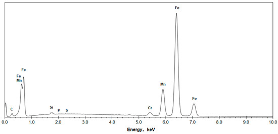
Figure 1.
A SEM-EDX spectrum of the sample steel.
Ball-on-disc sliding wear tests were performed on an universal macro-tribometer UMT-3MT (Center for Tribology, Inc. (CERT), Campbell, CA, USA) against a static cemented carbide ball (WC/Co, HV 15.5 GPa) of 6 mm in diameter. Figure 2 is a schematic sketch of the wear testing scheme. Prior to testing, the Hadfield steel sample was metallographically ground and polished to a scratch-free mirror finish.
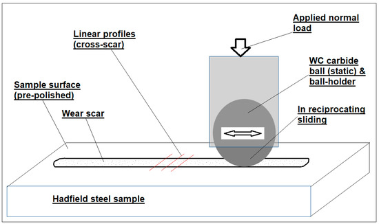
Figure 2.
A schematic sketch of the employed reciprocating sliding wear test.
The testing parameters were: applied normal load 49 N, reciprocating sliding length 8 mm and a constant reciprocating frequency 23.5 Hz. The initial ball-flat contact was estimated to have the maximum compressive stress of 2.9 GPa, which precluded the occurrence of severe plastic deformation. According to the measured diameter of the ball wear craters, the average ball-to-flat contact pressure was estimated to be 277 and 112 MPa prior to and after the second testing period, respectively. The testing sequence included a short wear period of 40 min, which led to 1880 reciprocating sliding passes and a sliding distance of 15.04 m. After removing the flat sample and the counterpart ball and measuring the resultant wear scar and the wear cap respectively, they were then reloaded into the same position to run the conformal sliding wear for 360 min, corresponding to 16,920 reciprocating sliding passes and a sliding distance of 135.36 m.
The wear scar and wear cap were measured using the 3D micrometer stage of the hardness tester. Figure 3 presents low-magnification SEM images of the obtained wear scar and wear cap. The as-obtained wear scar was full of loose wear debris and attachments of transferred material, as seen in Figure 3a. Prior to wear measurement, these were removed using an adhesive carbon tab. The cleaned wear scar is shown in Figure 3b. The wear scar measurements included three linear profiles in the middle 2-mm period of the 8-mm wear scar at a spatial resolution of 0.1 µm, as seen in Figure 2. Each line profile measurement was started from the as-polished flat surface to take five measurement points before entering the wear scar and completed by making another five measurement points at the as-polished flat surface after leaving the wear scar. These points served as a reference line of the flat surface to quantify the depth profile inside the width of the wear scar section. The ball wear cap shows a flat worn surface, Figure 3c. The ball cap measuring was made on the diameters both parallel and perpendicular to the sliding traces. These measurements were then processed to determine the volume loss and wear coefficient (i.e., volume wear at unit applied load and unit sliding distance, m3·N−1·m−1).
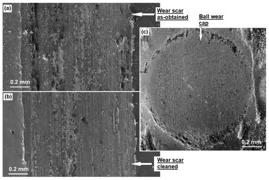
Figure 3.
(a) The as-obtained and (b) cleaned whole width of a wear scar, and (c) the wear cap of the counterpart.
The as-polished Hadfield steel sample and the wear scar were analysed on an Empyrean X-ray diffractometer (Malvern Panalytical BV, Almelo, The Netherlands) using a filtered Co radiation at a wavelength of 0.1789 nm (Kα1-Co). The instrument was operated at a slow scan speed of 0.0137°·s−1 and a step size of 0.053°. The scan was undertaken under the θ-2θ model in a range of diffraction angle (2θ) from 40° to 120° to include a number of austenite diffraction peaks. The penetration depth of the X-ray was estimated to be 3–8 µm [27]. The diffraction peaks were analysed using a Gaussian multiple peak-fitting technique to obtain the peak position (2θ) and breadth (β, standing for the full width at half maximum or FWHM). According to literature and our previous experimental research, a diffraction peak acquired from a homogeneous crystalline phase obeys a Gaussian distribution [28,29,30,31,32,33]. Previously, peak breadth measurements based on Gaussian distribution have been applied in quantitative characterisation of coherent precipitates in nickel alloys [29,30,31], lattice spacings of tetragonal martensites in medium-carbon steels [20,32] and nano-scale ordered domains in nitrided austenitic stainless steel [34]. According to the theory of X-ray diffraction, peak breadth reflects the severity of lattice distortion which can be caused by either microstrain or refined grain size [28,35,36]. Here the grain size is defined as the size of coherent domains for elastic X-ray scattering rather than the size measured using a microscope. The strain ε was estimated using the Wilson equation ε = [35,36]. The grain size t was estimated using the Scherrer equation t = , where λ stands for the X-ray wavelength [28,29,30,31].
A field-emission scanning electron microscope, FEISEM Nova200 (FEI Europe BV, Eindhoven, The Netherlands), was employed to investigate the worn surfaces both on the as-obtained wear scars and their transverse cross-sections. For the latter, specimens were prepared following a procedure of precise cutting, mounting in Bakelite, metallographic grinding and polishing, and chemical etching using a 2% nital etchant. Meanwhile, a longitudinal cross-section of the wear scar was prepared as a thin-foil specimen for TEM observation. The preparation followed a procedure of precise cutting, manual grinding and low-angle ion milling to a thickness of electron transparency [34,37]. The final ion beam thinning was carried out on a Gatan-691 precision ion polishing system (PIPS) using Ar-ions at the energy of 5 keV and low incident angles of ±5°. A field-emission transmission electron microscope, JEM 3100F (JEOL Ltd, Tokyo, Japan), operating at 200 kV, was employed to study wear-induced microstructure evolution beneath the worn surface.
3. Results
3.1. The Friction and Wear Properties
Figure 4 illustrates the variation of friction coefficient during the sliding wear. The running-in time prior to the stabilised friction was as short as 20 s or approximately 25 reciprocal passes, as shown in Figure 4a. The coefficient initiated at a low value less than 0.2 and quickly increased till stabilising at values above 0.5. According to previous research, such variation of friction coefficient was caused by initial formation of wear debris and its subsequent involvement in the sliding contact [21,38]. Figure 4b,c indicate that the friction coefficients both in the first period of 40 min and in the second period of 360 min were stabilised between 0.5 and 0.6.
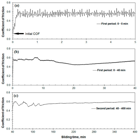
Figure 4.
The coefficient of friction plotted versus sliding distance: (a) the running-in friction in initial sliding; (b) the coefficient of friction in the 0–40 min period; and (c) the coefficient of friction in the 40–400 min period.
Figure 5 shows line profiles of the wear scars after 40 and 400 min of wear, respectively. Each curve presents an average of three line profiles. The 40-min profile consists of three parts with respect to a reference line as defined by the flat lengths besides the wear scar, namely, a valley in the middle and two raised bulges besides the valley. The valley area was measured to be 4.07 ± 0.30 × 10⁻⁹ m2 which stands for the gross loss due to wear and deformation. The raised bulges were measured to be 1.53 ± 0.05 × 10⁻⁹ m2 which recorded the sliding-induced plastic deformation. The deformation-induced bulges account for 38% of the gross loss, indicative of pronounced plastic deformation. Subsequently the net wear loss was determined to be 2.53 ± 0.33 × 10⁻⁹ m2.
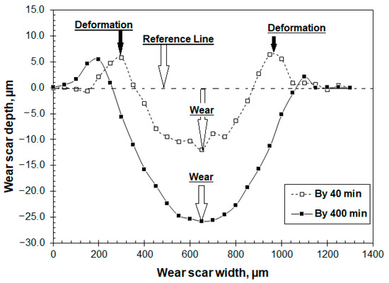
Figure 5.
Cross-sectional line profiles of wear scars of the Hadfield steel sample after the 40 and 400 min periods.
The 400-min profile also consists of three parts including a wear-induced valley and two deformation-induced bulges besides the wear scar. However, the latter is remarkably smaller than the greatly increased valley. Obviously, the wear scar in the second period of sliding wear (360 min of testing time) was predominantly the wear loss, and the plastic deformation at the edges became marginal.
Table 2 lists the measured volume losses and wear coefficients. The Hadfield steel shows a high coefficient of wear in the first 40-min period, namely, 2.75 ± 0.36 × 10⁻¹⁴ m3·N−1·m−1. In contrast, the average coefficient in the subsequent 360-min period decreased significantly to 1.26 ± 0.07 × 10⁻¹⁴ m3·N−1·m−1. The wear of the WC ball is much smaller than the austenitic steel, accounting for only 6–7% of the latter.
Table 2.
Volume losses and wear coefficients of the Hadfield steel and WC counterpart.
3.2. SEM and EDX Analyses of Worn Surfaces
Typical worn surface features of the Hadfield steel are shown in Figure 6. The wear scar is full of sliding traces in addition to a distribution of spalling detachments, Figure 6a. The wear scar also shows raised edges on both the upper and lower sides, which are consistent to the bulges shown in Figure 5. A typical bulge was observed in more detail, Figure 6b. The densely packed parallel lines are traces of slip bands and mechanical twining. In Figure 6c, the worn surface is continuously smooth, showing ploughing deformation and spalling wear. The exposed areas inside the spalling detachments exhibit rough grooves. One of the spalling detachments was observed at an even higher magnification, Figure 6d, where the edge presents cracks and brittle fragments and the exposed area exhibits ploughing deformation. These features suggest brittle spalling wear and severe deformation.
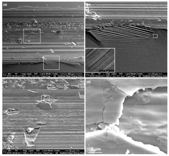
Figure 6.
SEM images of wear scar: (a) an overview of the whole width; (b) the built-up edge as highlighted in (a), including an inserted enlarged view of a small area; (c) the main worn surface as highlighted in (a); and (d) a spalling pattern as highlighted in (c).
In order to examine the brittle characteristics of the worn surface, a few Vickers’ indents were made on the cleaned smooth worn surface and subsequently observed by SEM, Figure 7. Spalling failures were found to take place on the edge of all the indents, Figure 7a. In Figure 7b, the spalling failure can be seen to have cracks, straight edges, and cleavage-like fracture. These reveal significant embrittlement of the worn surface. Moreover, the exposed area inside the spalling pit exhibits groove-like morphology similar to those shown in Figure 6d. The diagonals of the Vickers’ indents were measured, which turned out values of worn surface microhardness in the scale of HV0.05 8.2 ± 0.2 GPa. The microhardness is much higher than those measured at the subsurface depths, to be shown later, and is also higher than those reported in literature [5,6,7,9,10,11,13,14,15,16,17,26]. In addition, Figure 7b also shows that the worn surface exhibits fine fish-scale patterns. Such patterns are known to be produced by adhesive sliding contact with the involvement of transferred wear debris [37,38].
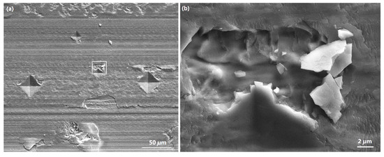
Figure 7.
SEM images showing indenting-induced spalling detachments on the worn surface: (a) an overview of a few Vickers’ indents made on the smooth worn surface, noting the indenting induced spalling at the edge of every indent; and (b) a high-resolution view of spalling failures outside the indent edge and the fine fish-scale patterns on the remaining worn surface.
SEM-EDX spectroscopic analyses were conducted to clarify the occurrence of oxidation wear. Figure 8a is a SEM secondary electron image showing one of the analysed areas, where spectroscopic analyses were applied in regions of worn surface (Points 6 and 9), spalling pit (Points 7 and 10), and wear debris agglomerating inside the spalling pit (Point 8). Figure 8b presents the acquired spectra of both the whole energy range (0–10 keV) and the low-energy end (0–1 keV, for improved energy resolution). Comparing to the strong intensity of O and W in the wear debris, the spectra acquired from other regions show very low O and W whereas the signals of Fe, Mn, and Cr are strong. Figure 8c–e are 2-dimensional mapping analyses of the characteristic X-rays of O-Kα1, Fe-Kα1, and W-Mα1 referring to the imaged area in Figure 8a, respectively. The wear debris show pronounced presence of O and W, indicating the oxidation wear and the wear of the WC counterpart, respectively. The detection of W in the wear debris is consistent to the observed wear of the WC counterpart, as shown in Figure 3c and Table 2. In addition, the worn surface also exhibits traces of oxygen, see Figure 8c. The non-uniform distribution of oxygen should be attributed to the transferred wear debris on the worn surface due to its adhesive bonding to the metallic worn surface, which is featured by the fish-scale patterns, as shown in the high-magnification observation in Figure 7b. The mapping analyses are consistent to the spectroscopic analysis that O and W existed only in a very thin film on the worn surface top.
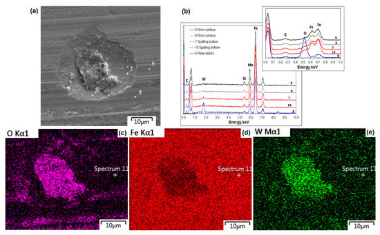
Figure 8.
SEM-EDX spectroscopic analyses of the worn surface: (a) an SEM image of the analysed worn surface; (b) spectra acquired in typical regions; (c) elemental map of O; (d) elemental map of Fe; and (e) elemental map of W.
In brief, the EDX analyses suggest that sliding-induced oxidation took place mostly in the wear debris. When wear debris was engaged in the sliding contact, it underwent extremely severe deforming and frictional heating. On the other hand, oxidation of the worn surface was much less.
3.3. Cross-Sectional SEM, Microhardness and TEM Analyses of Worn Surfaces
A transverse cross-section of the wear scar was observed to investigate wear-induced changes beneath the worn surface. Selected SEM observations are shown in Figure 9. Figure 9a was taken close to the middle of the wear scar. The subsurface contains dense deformation bands. The worn surface exhibits a wave-like top edge, which features ploughing deformation and matches to the groove-like patterns shown in Figure 6d and Figure 7b. Figure 9b was taken at the boundary area of the wear scar, serving as a cross-sectional view of the deformation-induced bulge shown in Figure 3 and Figure 5. The height of the bulge is approximately 20 µm. Twin bands can be found in the subsurface area. The deformation bands extended to a depth of about 0.15 mm, see Figure 9c. The images in Figure 9d,e were taken at a higher magnification to view more details of the worn surface deformation in depths of 8–10 µm, which reveal that the deformation bands became even denser in close vicinity of the worn surface. Spalling wear can be seen to have developed inside the severe deformation depth. This result is consistent to the brittle spalling failure as observed on the worn surface top, see Figure 6d and Figure 7b.
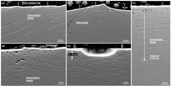
Figure 9.
SEM images of a transverse cross-section of the wear scar showing wear-induced subsurface deformation: (a) in the middle width; (b) at the boundary; (c) the whole depth of deformation bands; (d) a crack leading to spalling; and (e) a spalling pit.
Microhardness testing was undertaken to correlate the wear-induced deformation to the strain-hardening behaviour. The results are plotted in Figure 10. The top worn surface was hardened to HV0.025 6.0 GPa in a depth of 20 µm. Then the hardness dropped to the value of bulk hardness around 3.0 GPa in a depth of 120 µm. Compared to the cross-sectional SEM observation in Figure 9c, strain hardening took place in the depth range which showed pronounced deformation bands. More importantly, the worn surface reached a maximum hardness about HV0.025 6.4 GPa at a small depth within 5 µm. Because of instrumental limitation, the Vickers’ microhardness could not be measured up to further smaller depth approaching the worn surface. However, those indents made on the worn surface revealed a hardness of HV0.05 8.2 ± 0.2 GPa, see Figure 7a. Obviously, the extreme hardening was correlated to the severe deformation as shown in Figure 9d,e, and to the embrittlement as shown in Figure 6d and Figure 7b.
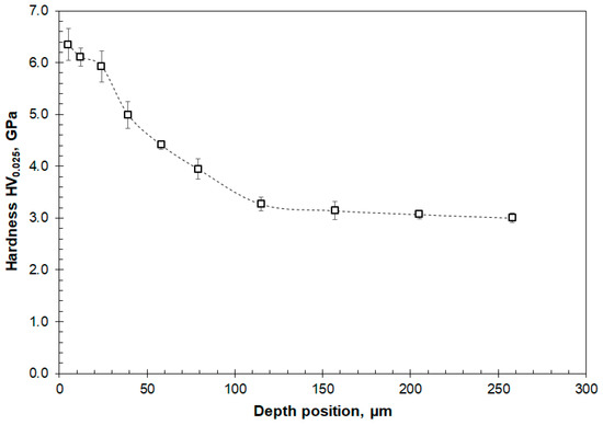
Figure 10.
The cross-sectional microhardness measured beneath the wear scar plotted versus the depth position.
Figure 11, Figure 12 and Figure 13 show TEM bright-field images of a longitudinal cross-section of the wear scar. In the close vicinity of the worn surface, the microstructure exhibits a laminated morphology, Figure 11a. The highlighted areas marked A and B are at 240 and 500 nm beneath the worn surface, respectively. The laminate widths in areas A and B were measured to be 24.6 and 32.6 nm, respectively. Figure 11b is a low-magnification BF image showing microstructure evolution from the worn surface top (labelled by arrows) to a depth of 5 µm. The highlighted areas, marked A, B, to E, were observed further at higher magnifications as shown in Figure 12 and Figure 13.
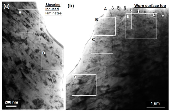
Figure 11.
Longitudinal cross-sectional TEM images of worn sample: (a) laminated austenite microstructure in subsurface; and (b) microstructure evolution from the worn surface top to certain depth.
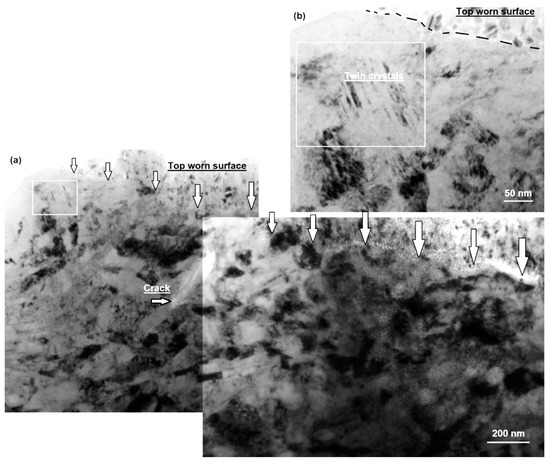
Figure 12.
Wear-induced nanostructure in close vicinity of the worn surface. Nano-size twins in the top region of image (a) are shown at higher magnification in image (b).
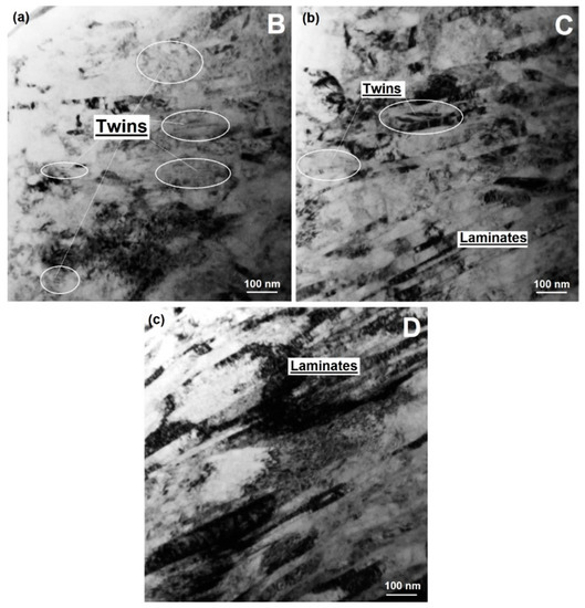
Figure 13.
TEM bright field micrographs showing wear-induced deformation at depths of (a) 0.8 µm, (b) 1.9 µm, and (c) 4.2 µm.
Figure 12 shows high-magnification bright field images of the top part referring to the highlighted area A and E in Figure 11b, including the upmost edge of the wear scar (labelled by arrows in Figure 12a). The top of the worn surface is marked by arrows in Figure 11b and Figure 12a, which does not show a straight edge. The observed rough edge is consistent with the SEM observations in Figure 6d, Figure 7b and Figure 9, reflecting ploughing deformation. The subsurface microstructure exhibited equaxial granular morphology in a depth up to 1.5 µm, which differed clearly from the nano-laminates observed at further depths (See Figure 11a and Figure 13a–c). A crack can be seen to have been formed beneath the worn top, which provided a further evidence of straining-induced embrittlement. In the upper-left part of Figure 12a, a small area is highlighted to contain parallel needle-like grains. Figure 12b provides further details of this area, indicating nano-twins.
Figure 13 shows bright field images of the subsurface microstructure at the depths of 0.8, 1.9, and 4.2 µm, respectively, seeing the highlighted zones B–D in Figure 11b. All the imaged areas exhibited laminated morphology. The thickness of a single laminated layer scaled at about tens of nanometres. Moreover, some areas within a depth of 2 µm show small parallel needle-like grains, such as those being marked in Figure 13a,b. These observations verified the occurrence of twinning deformation at the upmost of sliding worn surface. Such twins were rarely found at further depths beyond 2 µm.
In literature, mechanical twining has been known as a major deformation mode leading to severe strain-hardening of Hadfield steel [10,11,26]. The twins observed in current research differ from those reported in the literature in that, nanotwins accounted for only a minor proportion as compared to the majority of laminates. Nevertheless, the TEM observations revealed a gradient distribution of the nano-scale microstructure in close vicinity of the worn surface from equaxial nanocrystalline, nanotwins to nano-laminates.
3.4. X-ray Diffraction Analyses of Worn Surfaces
Figure 14 shows the XRD curves of both the as-polished bulk steel and the worn surface. According to the estimated X-ray penetration depth (3.1–8.1 µm), the results should refer to the depth similar to the depth being observed in the cross-sectional TEM as shown in Figure 11, Figure 12 and Figure 13. In Figure 14a, five diffraction peaks acquired inside the worn scar, namely the (111), (200), (220), (311), and (222) peaks of austenite, exhibit pronounced broadening. In contrast, the diffraction peaks of the bulk steel are remarkably narrow. The broaden peaks imply substantial lattice distortion resulted from the wear-induced microstructure evolution, see Figure 9, Figure 10, Figure 11, Figure 12 and Figure 13.
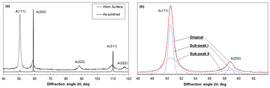
Figure 14.
X-ray diffraction curves of the Hadfield steel: (a) Comparison between the as-polished bulk steel and the worn surface; (b) Gaussian fitting analysis of the (111) and (200) peaks of the worn surface.
In addition to broadening, the diffraction peaks exhibit abnormal shapes which do not fit to a single Gaussian distribution. From our knowledge, such a phenomenon has not been reported before. However, it is known that a single phase in a polycrystalline alloy normally fits to a single Gaussian distribution [28,29,30,31,32]. Consequently, we attempted to fit each diffraction peak using two Gaussian distributions of different breadth parameters. The fitting was quite successful, as shown by the example of the completed fittings in Figure 14b. Therefore, the obtained diffraction peaks are believed to be overlapping peaks of two crystalline substructures with different homogeneity. Such heterogeneous substructures were not reported in deformed polycrystalline before but have been found in the mixed lath- and plate-martensites of martensitic steels [20,32], and also in several nickel alloys with coherent precipitates [29,30,31]. In this work, we interpret the heterogeneous substructure of the deformed Hadfield steel as the heterogeneity in its plastic deformation. Then the peak positions and peak breadths derived from the Gaussian fittings were adopted to estimate the microstrain and grain size (i.e., size of domains generating coherent scattering of diffracting X-ray) of the substructures. Although further microstructure characterisation is required to support the interpretation, numerous electron microscopic studies of deformed Hadfield steels have reported the heterogeneous distribution of substructures, such as mechanical twins and nanocrystalline [5,9,10,11,16,17,26]. Mechanical twins and nano-laminates were also found in current work, Figure 9, Figure 10, Figure 11, Figure 12 and Figure 13. The quantitative results are summarised in Table 3. The sliding wear increased the lattice strain from 0.15 ± 0.08 % of the bulk steel to 1.34 ± 0.57 %, whereas the grain size was greatly decreased from 49 ± 11 nm to 3 ± 1 nm.
Table 3.
The full-width at half-maximum (FWHM, β) of diffraction peaks and the estimated lattice strain(ε) and grain size (t) of the bulk and worn Hadfield steel.
In addition, the X-ray diffraction revealed no wear-induced martensitic structure. This finding indicates that the steel retained its austenitic structure despite the extremely severe deformation.
4. Discussion
4.1. The Friction and Wear Properties of Hadfield Steel
In this work, the Hadfield steel was evaluated under reciprocating sliding friction and wear condition for a long period of 400 min, in which the total sliding passes were 16,920 and the sliding distance 135.36 m. The coefficient of friction, despite some scale of variation in the initial running-in period, was mostly stabilised in a range 0.5–0.7 (Figure 4). It reflected the sliding friction between the WC counterpart and hardened Hadfield steel with involvement of a third part, i.e., the wear debris and the associated adhesive attachments on the worn surface (Figure 6d and Figure 7b). The post-wear examinations of the worn surfaces revealed that the friction behaviour was dominated by the engagement of wear debris in the sliding contact zone, especially when a Fe-Mn-O based tribofilm was generated to adhere on the worn surface (Figure 8b,c). The friction behaviour is similar to those of various martensitic and bainitic steels being tested under the same conditions [20].
The wear coefficient of the Hadfield steel was determined to be in the scale of 10−14 m3·N−1·m−1 (Table 2). The first test, i.e., the 0–40 min period, recorded a wear coefficient of 2.75 × 10⁻¹⁴ m3·N−1·m−1, whereas it dropped to 1.26 × 10⁻¹⁴ m3·N−1·m−1 in the remaining testing period. This can be explained by the fact that the initial sliding wear of Hadfield steel experienced severe plastic deformation and adhesive wear due to its low hardness and good plasticity [21]. The severe deformation took place not only in a depth beneath the sliding contact zone (Figure 6) but also extended to the adjacent volume besides the wear scar (Figure 5, Figure 6b, and Figure 9b). It is worthwhile to conduct further experimental study to investigate the effect of high-scale straining and strain-hardening on the wear coefficient and on the associated microstructure evolution. Nevertheless, the second testing period should mainly reveal that the wear behaviour of strain hardened Hadfield steel for the worn surface was hardened to above HV0.025 6 GPa (Figure 10). The hardened Hadfield steel still exhibited high coefficient of wear as compared to medium-carbon martensitic steels which showed wear coefficients in the scale of 10−15 × m3·N−1·m−1 [20]. This reveals the inferior resistance of Hadfield steel to sliding wear.
4.2. Sliding-Induced Microstructure Evolution and Strain Hardening
A significant feature in the sliding wear of the Hadfield steel is the pronounced plastic deformation. The deformation was attributed to its low hardness, i.e., HV 2.1 GPa as measured on the bulk steel. This behaviour has been known in many deformation-related failures of mechanical components made from Hadfield steel, such as railway crossings, impact hammers, and jaw crushers [3,5,6,7,8,9,10,12,21,39]. Wear-induced deformation and hardening of Hadfield steel has been widely reported in literature [3,5,7,8,9,22,26,39]. In current research, the depth of subsurface hardening matched well to the depth of deformation bands and mechanical twins, comparing Figure 9c and Figure 10.
In the close vicinity of the worn surface where the hardness was higher than HV0.025 6 GPa, the deformation caused extremely severe changes in the microstructure. It was obvious from the XRD analysis that the sliding wear did not give rise to any transformation of the deformed austenite to martensite. This clarification agrees well to most cases of wear and other means of mechanical loading of Hadfield steels [4,8,16,17,21]. However, TEM observations revealed a mixture of nano-scale substructures of deformation laminates (Figure 11 and Figure 13), equaxial grains (Figure 11b and Figure 12a), and mechanical twins (Figure 12b and Figure 13). The combined cross-sectional SEM and TEM observations reveal deformation-induced microstructure evolution of the austenite from increasing deformation bands and mechanical twins to nano-laminates, and to nanocrystalline. Such wear-induced nanocrystallisation was reported in various circumstances of Hadfield steel and other metallic alloys [18,23,25,26,39].
Moreover, mechanical twining was found to take place in some nano crystallites close to the worn surface (Figure 12b), which was not reported in previous TEM observations. The quantitative XRD analysis indicates strong heterogeneity of the highly deformed microstructure (Figure 14b and Table 3). Unlike TEM which reveals microstructure characteristics mostly of extremely small sample volumes, XRD characterises crystalline structures in volumes as large as millimetres. The results are interpreted in a statistic basis. The applications of XRD analysis in worn surface characterisation were not as popular as other techniques [24,25,40]. In current work, we applied detailed XRD analysis on the worn surface of Hadfield steel, which has shown its strong complementary to electron microscopy. In addition, XRD provides analyses without the need of complex sample preparation.
4.3. Spalling Wear and Its Relation to the Sliding-Induced Surface Embrittlement
Whereas the Hadfield steel exhibited substantially higher coefficient of wear than other martensitic and bainitic steels under the same reciprocating sliding condition, comparing Table 2 and those reported in previous work [20], deformation-induced spalling failure has been found to be the predominant wear mechanism (Figure 3 and Figure 6). Such spalling wear occurred not only in the austenitic Hadfield steel, but also in steels with other microstructures and in other metallic alloys [19,20,21,22,23,39,41,42]. Most previously published work correlated the spalling wear to the extremely hardened worn surfaces, however the current work reveals that the spalling wear was attributed to the deformation-induced worn surface embrittlement, which can be seen not only in the fine brittle features in the spalling pits (Figure 6d) but also in the indentation-induced brittle spalling (Figure 7).
The embrittlement was a sequence of the structure nanocrystallisation. Despite the beneficial effect of the nanocrystallisation in the extreme strain hardening, obviously it brought about structural embrittlement. Similar nanocrystallisation-induced surface embrittlement was reported in shot peened Hadfield steel [16,17]. In that research, certain severity of peening did result in significant strain hardening and subsequently increased the sliding wear resistance under relatively low loads. On the other hand, over-peening with extra bombarding time led to increased wear at high loads due to pronounced spalling wear.
In addition to the observed spalling wear, tribo-oxidation was also confirmed by SEM-EDX analysis. The oxidation, however, was found to be concentrated in the agglomerates of wear debris and in the adhered tribofilms on the worn surface. Similar oxidised wear debris was also generated in the wear of other steels under the same sliding conditions [20]. Comparing between the Hadfield steel and those martensitic and bainitic steels, the substantial different wear coefficients can only be explained by the occurrence of deformation-induced spalling wear.
5. Conclusions
A sample of high-carbon and high-manganese austenitic steel, Hadfield steel, was experimentally studied for sliding wear and friction properties in a dry reciprocal sliding wear test. The resultant worn surface was extensively characterised using analytical SEM, TEM, XRD, and micro-hardness test. The research leads to the following conclusions.
- The Hadfield steel showed a coefficient of wear in the scale of 10−14 m3·N−1·m−1 and a coefficient of friction of 0.5–0.6.
- The steel still retained its austenitic structure in the sliding wear without any detectable evidence of deformation-induced martensite transformation.
- The steel encountered severe plastic deformation beneath the worn surface. The deformation led to significant work hardening and surface embrittlement. Deformation-induced spalling wear was found as the predominant wear mechanism. Tribo-oxidation was also observed in the resultant wear debris.
- The surface embrittlement and spalling wear was associated with the deformation-induced nano-heterogeneous microstructure including nano-laminate, nanotwins, and nanocrystalline beneath the worn surface.
Author Contributions
Q.L. contributed to the conceptualization, experimental investigation, and writing of the paper. J.Z. contributed to the conceptualization, sample materials, data analysing and discussion of the paper. All authors have read and agreed to the published version of the manuscript.
Funding
This research received no external funding.
Institutional Review Board Statement
Not applicable.
Informed Consent Statement
Not applicable.
Data Availability Statement
Not applicable.
Conflicts of Interest
The authors declare no conflict of interest.
References
- Gauzzi, F.; Rossi, M.; Verdini, B. Cold-Working induced martensitic transformation in 12 percent Mn austenitic steel (Hadfield steel). Metall. Ital. 1971, 63, 555. [Google Scholar]
- Tweedale, G.; Paton, W.D.M. Sir Robert Abbott Hadfield F.R.S (1858–1940) and the discovery of manganese steel, Notes and Records. R. Soc. J. Hist. Sci. 1985, 40, 63. [Google Scholar]
- Dastur, Y.N.; Leslie, W.C. Mechanism of work-hardening in Hadfield manganese steel. Metall. Trans. A 1981, 12, 749–759. [Google Scholar] [CrossRef]
- Xie, J.P.; Wang, W.Y.; Li, J.W.; Wang, A.Q.; Zhao, Y.R.; Li, L.L. Wear Resistant Austenitic Manganese Steels; Science Press: Beijing, China, 2008. [Google Scholar]
- Harzallah, R.; Mouftiez, A.; Felder, E.; Harriri, S.; Maujean, J.P. Rolling contact fatigue of Hadfield steel X120Mn12. Wear 2010, 269, 647–654. [Google Scholar] [CrossRef]
- Dalai, R.; Das, S.; Das, K. Effect of thermo-mechanical processing on the low impact abrasion and low stress sliding wear resistance of austenitic high manganese steels. Wear 2019, 420, 176–183. [Google Scholar] [CrossRef]
- Lv, Y.; Li, S.; Chen, F.; Zhu, R.; Lei, T. On the impact abrasive wear of super-high manganese steel. Acta Metall. Sinica 1999, 35, 581–584. [Google Scholar]
- Cai, C.; Song, R.; Liu, S.; Feng, Y.; Pei, Z. Wear behaviour and subsurface layer work hardening mechanism of Fe-24. 1Mn-1.21C-0.48Si steel. Procedia Eng. 2017, 207, 2251–2256. [Google Scholar]
- Machado, P.C.; Pereira, J.I.; Sinatora, A. Abrasive wear of austenitic manganese steels via jaw crusher test. Wear 2021, 476, 203726. [Google Scholar] [CrossRef]
- Machado, P.C.; Pereira, J.I.; Sinatora, A. Subsurface microstructural dynamic recrystallization in multiscale abrasive wear. Wear 2021, 486–487, 204111. [Google Scholar] [CrossRef]
- Efstathiou, C.; Sehitoglu, H. Strain hardening and heterogeneous deformation during twinning in Hadfield steel. Acta Mater. 2010, 58, 1479–1488. [Google Scholar] [CrossRef]
- Allende-Seco, R.; Artigas, A.; Bruna, H.; Carvajal, L.; Monsalve, A.; Sklate-Boja, M.F. Hardening by Transformation and Cold Working in a Hadfield Steel Cone Crusher Liner. Metals 2021, 11, 961. [Google Scholar] [CrossRef]
- Lychagin, D.V.; Filippov, A.V.; Novitskaya, O.S.; Chumlyakov, Y.I.; Kolubaev, E.A.; Lychagina, L.L. Deformation of Hadfield steel single crystals by dry sliding friction with the normal load/friction force orientations []/[10] and []/[001]. Tribo. Int. 2020, 147, 106284. [Google Scholar] [CrossRef]
- Lychagin, D.V.; Filippov, A.V.; Novitskaya, O.S.; Kolubaev, A.V.; Moskvichev, E.N.; Fortuna, S.V.; Chumlyakov, Y.I. Deformation and wera of Hadfield steel single crystals under dry sliding friction. Wear 2022, 488–489, 204126. [Google Scholar] [CrossRef]
- Zhang, F.; Lv, B.; Wang, T.; Zheng, C.; Zhang, M.; Luo, H.; Liu, H. Microstructure and properties of purity high Mn steel crossing explosion hardened. ISIJ Int. 2008, 48, 1766–1770. [Google Scholar] [CrossRef][Green Version]
- Yan, W.; Fang, L.; Sun, K.; Xu, Y. Effect of surface nanocrystallization on abrasive wear properties in Hadfield steel. J. Xi’an Jiaotong Univ. 2007, 41, 634–641. [Google Scholar] [CrossRef]
- Yan, W.; Fang, L.; Sun, K.; Xu, Y. Effect of surface hardening on wear behaviour of Hadfield steel. Mater. Sci. Eng. 2007, 460–461, 542–549. [Google Scholar] [CrossRef]
- Inman, I.A.; Datta, P.K.; Du, H.L.; Burnell-Gray, J.S.; Pierzgalski, S.; Luo, Q. Studies of high temperature sliding wear of metallic dissimilar interfaces. Tribo Int. 2005, 38, 812–823. [Google Scholar] [CrossRef]
- Cao, Y.G.; Yin, C.H.; Liang, Y.L.; Tang, S.H. Lowering the coefficient of martensitic steel by forming a self-lubricating layer in dry sliding wear. Mater. Res. Exp. 2019, 6, 055024. [Google Scholar] [CrossRef]
- Luo, Q.; Li, J.; Yan, Q.; Li, W.; Gao, Y.; Kitchen, M.; Bowen, L.; Farmilo, N.; Ding, Y. Sliding wear of medium-carbon bainitic/martensitic/austenitic steel treated by short-term low-temperature austempering. Wear 2021, 476, 203732. [Google Scholar] [CrossRef]
- Li, C.; Deng, X.; Wang, Z. Friction behaviour and self-lubricating mechanism of low alloy martensitic steel during reciprocating sliding. Wear 2021, 482–483, 203972. [Google Scholar] [CrossRef]
- Yin, C.H.; Liang, Y.L.; Jiang, Y.; Yang, M.; Long, S.L. Formation of nano-laminated structures in a dry sliding wear induced layer under different wear mechanisms of 20CrNi2Mo steel. Appl. Surf. Sci. 2017, 423, 305–313. [Google Scholar] [CrossRef]
- Su, Y.S.; Li, S.X.; Gao, Q.Y.; Jiang, H.; Lu, S.Y.; Yu, F.; Shu, X.D. Evolution of nano-laminated structure formed by the thermally-assisted plastic deformation in dry sliding wear. Tribo Int. 2019, 140, 105846. [Google Scholar] [CrossRef]
- Shariff, S.M.; Pal, T.K.; Padmanabham, G.; Joshi, S.V. Comparative study on dry sliding wear behaviour of various railroad steels. Trans. ASME J. Tribo 2011, 133, 021602. [Google Scholar] [CrossRef]
- Korshunov, L.G.; Chernenko, N.L. Effect of aluminium on the structural transitions and the wear resistance of Hadfield steel under friction. Phys. Met. Metall. 2018, 119, 700–706. [Google Scholar] [CrossRef]
- Chen, C.; Lv, B.; Ma, H.; Sun, D.; Zhang, F. Wear behaviour and the corresponding work hardening characteristics of Hadfield steel. Tribo Int. 2018, 121, 389–399. [Google Scholar] [CrossRef]
- Luo, Q. A modified X-ray diffraction method to measure residual normal and shear stresses of machined surfaces. Int. J. Adv. Manufact. Technol. 2022, 119, 3595–3606. [Google Scholar] [CrossRef]
- Cullity, B.D.; Stock, S.R. Elements of X-ray Diffraction; Pearson Education Ltd.: Harlow, UK, 2014; p. 379. [Google Scholar]
- Lahrman, D.F.; Field, R.D.; Darolia, R.; Fraser, H.L. Investigation of techniques for measuring lattice mismatch in a rhenium containing nickel based superalloy. Acta Metall. 1988, 36, 1309–1320. [Google Scholar] [CrossRef]
- Mukherji, D.; Gilles, R.; Barbier, B.; Del Genovese, D.; Hasse, B.; Strunz, P.; Wroblewski, T.; Fuess, H.; Rösler, J. Lattice misfit measurement in Inconel 706 containing coherent γ’ and γ” precipitates. Scrip. Mater. 2003, 48, 333–339. [Google Scholar] [CrossRef]
- Luo, Q.; Chi, K.; Li, S.; Barnard, P. Microstructural Stability and Lattice Misfit Characterisations of Nimonic 263. In Proceedings of the ASME 2012 Pressure Vessels & Piping Division Conference (PVP2012), Toronto, ON, Canada, 15–19 July 2012; Volume 6, PTS A & B. pp. 197–206. [Google Scholar]
- Luo, Q. A new XRD method to quantify plate and lath martensites of hardened medium-carbon steel. J. Mater. Eng. Perform. 2016, 25, 2170–2179. [Google Scholar] [CrossRef]
- Luo, Q. Characterization of short-range ordered domains using quantitative X-ray diffraction. Nanosci. Nanotechnol. Lett. 2018, 10, 835–842. [Google Scholar] [CrossRef]
- Luo, Q.; Oluwafemi, O.; Kitchen, M.; Yang, S. Tribological properties and wear mechanisms of DC pulse plasma nitrided austenitic stainless steel in dry reciprocating sliding tests. Wear 2017, 376–377, 1640–1651. [Google Scholar] [CrossRef]
- Badawi, E.A.; Abdel-Rahman, M.A.; Mostafa, A.; Abdel-Rahman, M. Determination of the crystallite size and micro-strain by novel method from XRD profile. Appl. Phys. 2019, 2, 1–15. [Google Scholar]
- Shafi, P.M.; Bose, A.C. Impact of crystalline defects and size on X-ray line broadening: A phenomenological approach for tetragonal SnO2 nanocrystals. AIP Adv. 2015, 5, 057137. [Google Scholar] [CrossRef]
- Luo, Q. Electron microscopy and spectroscopy in the analysis of friction and wear mechanisms. Lubricants 2018, 6, 58. [Google Scholar] [CrossRef]
- Luo, Q. Origin of friction in running-in sliding wear of nitride coatings. Tribo Lett. 2010, 37, 529–539. [Google Scholar] [CrossRef]
- Zhang, F.; Lv, B.; Zheng, C.; Zhang, M.; Yang, S.; Yan, Z. Failure mechanism and worn surface microstructure of high manganese steel and bainite steel crossings. Chin. J. Mech. Eng. 2008, 44, 232–238. [Google Scholar] [CrossRef]
- Emurlaev, K.; Gerasimenko, T.; Abdimazhan, D. Nondestructive evaluation of material state near the friction interface under dry sliding. Mater. Today Proc. 2021, 38, 1526–1529. [Google Scholar] [CrossRef]
- Lee, K.M.; Polycarpou, A.A. Wear of conventional pearlitic and improved bainitic steels. Wear 2005, 259, 391–399. [Google Scholar] [CrossRef]
- Luo, Q.; Mei, H.J.; Kitchen, M.; Gao, Y.; Bowen, L. Effect of short-term low-temperature austempering on the microstructure and abrasive wear of medium-carbon low-alloy stee. Met. Mater. Int. 2021, 27, 3115–3131. [Google Scholar] [CrossRef]


Publisher’s Note: MDPI stays neutral with regard to jurisdictional claims in published maps and institutional affiliations. |
© 2022 by the authors. Licensee MDPI, Basel, Switzerland. This article is an open access article distributed under the terms and conditions of the Creative Commons Attribution (CC BY) license (https://creativecommons.org/licenses/by/4.0/).